EP3629686A1 - Device for pressing of components - Google Patents
Device for pressing of components Download PDFInfo
- Publication number
- EP3629686A1 EP3629686A1 EP18196828.0A EP18196828A EP3629686A1 EP 3629686 A1 EP3629686 A1 EP 3629686A1 EP 18196828 A EP18196828 A EP 18196828A EP 3629686 A1 EP3629686 A1 EP 3629686A1
- Authority
- EP
- European Patent Office
- Prior art keywords
- components
- carrier plate
- spring arm
- hollow body
- heat sink
- Prior art date
- Legal status (The legal status is an assumption and is not a legal conclusion. Google has not performed a legal analysis and makes no representation as to the accuracy of the status listed.)
- Pending
Links
Images

Classifications
-
- H—ELECTRICITY
- H05—ELECTRIC TECHNIQUES NOT OTHERWISE PROVIDED FOR
- H05K—PRINTED CIRCUITS; CASINGS OR CONSTRUCTIONAL DETAILS OF ELECTRIC APPARATUS; MANUFACTURE OF ASSEMBLAGES OF ELECTRICAL COMPONENTS
- H05K7/00—Constructional details common to different types of electric apparatus
- H05K7/20—Modifications to facilitate cooling, ventilating, or heating
- H05K7/2039—Modifications to facilitate cooling, ventilating, or heating characterised by the heat transfer by conduction from the heat generating element to a dissipating body
- H05K7/20436—Inner thermal coupling elements in heat dissipating housings, e.g. protrusions or depressions integrally formed in the housing
- H05K7/2049—Pressing means used to urge contact, e.g. springs
Definitions
- the present invention relates generally to the field of electrical and electronic devices, in particular to the area of switching power supplies and power electronic circuits.
- the present invention relates to a device for pressing components mounted on a carrier plate onto a heat sink.
- the components are cooled via the carrier plate or the components are contacted with the carrier plate.
- the heat sink is arranged on a side of the carrier plate not equipped with components at least in a region of thermal contacting or in a cooling region.
- Devices especially electrical or electronic devices such as Switched-mode power supplies, power electronic circuits, control devices, etc. are usually built up today from electrical components and / or assemblies.
- the components are attached to a carrier plate - a so-called printed circuit board - which is used for mechanical fastening and for so-called conductor tracks for an electrical connection of the components.
- the components can e.g. by means of soldering on soldering surfaces or in eyes, by means of gluing, etc. and, in the case of larger components, by means of screws on the circuit board.
- the switching of a device comprises semiconductor components such as, for example, power semiconductor elements, etc., from which a mostly thermal energy loss - ie heat - is produced.
- semiconductor components such as, for example, power semiconductor elements, etc.
- a mostly thermal energy loss - ie heat - is produced.
- damage or overheating of the respective to prevent component or the circuit or a malfunction of the device by the power loss or heat, it is necessary to cool these power loss producing components accordingly or to dissipate the heat produced.
- the carrier board or printed circuit board, on which the semiconductor components which produce or are to be cooled are located is usually connected to a heat-dissipating part - a so-called heat sink.
- a so-called thermal bridge is formed from the heat sink, which usually consists of a highly thermally conductive metal, usually aluminum or copper, in order to conduct the heat generated away from the component to be cooled and e.g. to be delivered to a device environment.
- Heat sinks are used, for example, in power electronics, in control units, etc. primarily for cooling power semiconductors (e.g. power diodes, power transistors, etc.).
- the heat sink can be excluded, for example, on one side, which is at least in a region of heat-producing components or components to be cooled - ie in a cooling region - from being fitted with components, or on an underside of the Carrier plate can be arranged adjacent. That is, the heat loss or power loss generated by a component is then conducted from the component through the carrier plate to the heat sink or the carrier plate is located between the heat sink and a component to be cooled.
- heat sinks In order to promote heat dissipation, heat sinks require a good thermal connection to the component to be cooled. It is therefore necessary to establish as close and good a contact as possible between the heat sink and the component to be cooled. To compensate for unevenness e.g. between the underside of the carrier plate and a surface of the heat sink and in order to produce better heat transfer to the heat sink, e.g. a thin layer of thermal grease is applied.
- the inserted electrically insulating layer and / or the insulation elements can be used, for example, to compensate for unevenness and to improve the heat transfer.
- the component In order to produce the correspondingly close and good thermal contact between the component to be cooled and the heat sink, the component is usually also pressed against the heat sink.
- Spring plates are used, which are arranged, for example, on the components to be cooled and fastened by means of screws or clips. The spring plates then cause e.g. a contact pressure which presses the components against the carrier plate and thus against the heat sink arranged on the underside of the carrier plate.
- the use of spring plates for pressing components has the disadvantage that assembly usually has to be carried out manually and is relatively expensive.
- the invention is therefore based on the object of specifying a device for pressing components onto a heat sink, which is simple and inexpensive to assemble with little expenditure of time and enables a space-saving arrangement of the components while maintaining predetermined voltage spacings.
- the object is achieved by a device of the type described in the introduction with the features of the independent claim.
- Advantageous embodiments of the present invention are described in the dependent claims.
- the object is achieved by a device of the type described at the outset for pressing components which are arranged and attached to a carrier plate to a heat sink.
- the components are cooled via the carrier plate and / or the components are contacted.
- the heat sink is arranged on a side or underside of the carrier plate which is not equipped with components in the region of the components to be cooled.
- the device according to the invention comprises at least one hollow body and at least one spring arm.
- the hollow body is set up at least to receive a fastening body, which can be attached directly to the heat sink, for example, and with which the device can be fastened. Furthermore, the device has a spring arm, which is curved and one end of the spring arm has a support surface for transmitting a contact pressure to a component to be cooled.
- the main aspect of the solution proposed according to the invention is that the device can be attached simply and in a time-saving manner - in a relatively short assembly time - to the carrier plate or during the manufacture or assembly of the circuit or of the electrical device.
- the device is suitable for automated assembly.
- the device enables a space-saving arrangement of the components on the carrier plate, and thus a space-saving configuration of the circuit, especially due to the configuration of the at least one spring arm.
- electrical devices such as Switching power supplies, etc.
- the device is designed such that, in an assembled state, a predetermined minimum voltage distance or a predetermined minimum distance for the creepage distance between contacting the component to be cooled and the fastening body and / or a fastening means for fixing the device to the carrier plate is observed.
- the shortest distance along a surface of a solid insulating material between two conductive parts such as, for example, conductor tracks on the carrier plate or a contacting or through-contacting of a component and, for example, a fastening body or a fastening means made of metal is used as the creepage distance.
- At least the spring arm is designed to be at least quarter-circle curved.
- the contact pressure can be very easily transmitted to the component via the contact surface.
- the curvature of the spring arm has the task of providing sufficient spring travel and thereby making it possible for components to be cooled to be arranged so close to one another or to live parts (e.g. conductor tracks, etc.) while observing predetermined voltage or safety distances.
- the at least one spring arm also has a relatively high mechanical strength and is space-saving.
- An omega-like curved configuration of the spring arm has proven to be particularly favorable, by means of which very short distances from components to be cooled to one another and / or from live parts while maintaining the specified voltage spacings and good pressure on components to be cooled are made possible. Furthermore, the device is easy to grasp and place due to an omega-shaped spring arm, but especially with two or more omega-shaped spring arms in an automated assembly, for example by means of a robot arm.
- the spring arm can ideally have a circular or square or rectangular cross section.
- the contact pressure can be transferred to the component to be cooled, for example over a circular or square surface - more concentrated - or distributed over a rectangular surface, or the contact surface e.g. can be adapted to a component size.
- the bearing surface at the end of the at least one spring arm is designed as a polygonal flattening.
- the hollow body of the device according to the invention is designed in such a way that a fastening means can be introduced which can be detachably or non-releasably connected to the fastening body for assembly.
- the hollow body can have a bore in which the fastening means (e.g. screw, rivet) can be introduced.
- the fastening means can then be used in the assembly of the device according to the invention with the fastening body located inside the hollow body, which e.g. attached to the heat sink.
- an inner diameter of the hollow body is configured such that insulation can be inserted between an inner wall of the hollow body and the fastening body.
- the hollow body of the device according to the invention has an anti-twist device, by means of which twisting of the device during placement and fastening is simple is prevented. In particular, automated assembly is facilitated and simplified.
- the device is made in one piece from elastic material - ideally as a plastic injection molded part. This shortens and simplifies assembly, since only one part has to be attached for pressing on at least one component. As a result, the assembly costs are reduced and the devices or circuits can be manufactured in a more space-saving, faster and cheaper manner.
- the use of an elastic material - especially plastic - for the device when used in an electrical device does not lead to any direct EMC effects - i.e. there are therefore no unwanted electrical and / or electromagnetic effects caused by the device which could interfere with the functioning of the electrical device.
- high-performance plastics e.g.
- Figure 1 shows a schematic view of an exemplary embodiment of the device 1 according to the invention for pressing a component 7a, 7b mounted on a carrier plate or printed circuit board 8 against a heat sink 9 in an oblique view.
- the device 1 is made in one piece from an elastic and optionally insulating material and can be produced, for example, by means of an injection molding process as a plastic injection molded part.
- the device 1 comprises a hollow body 2, which can be designed, for example, as a hollow cylinder. Alternatively, the hollow body 2 can also have a square or rectangular cross section.
- the hollow body is for receiving at least one fastening body 10 - as shown in FIG Figure 3 is explained in more detail - set up.
- An inner diameter of the hollow body 2 is configured such that at least the fastening body 10 can be inserted into the hollow body 2. If necessary, the inner diameter of the hollow body 2 can be configured such that insulation 14 can also be inserted, for example for a higher dielectric strength or for increasing a voltage gap between contacting of the component 7a, 7b and the fastening body 10.
- the hollow body 2 has an outlet 3 on an upper side in the mounting direction M.
- a fastening means 15 for example a screw or a rivet
- the fastening means 15 can be introduced into this outlet 3, said fastening means being releasably or non-releasably connectable to the fastening body 10.
- the device 1 is fastened and the component 7a, 7b pressed by a pressing force F against the carrier plate 8 or the heat sink 9.
- the hollow body 2 has an anti-twist protection 4 which projects beyond an end of the hollow body which is lower in the mounting direction M and can engage, for example, in corresponding outlets of the carrier plate 8.
- the device 1 has a spring arm 5 which is curved.
- the spring arm 5 shown is, for example, omega-shaped or shaped similar to the Greek capital letter Omega Q. In the simplest case, the spring arm 5 can be curved at least in a quarter circle.
- the spring arm 5 merges into the upper surface of the hollow body 2 in the mounting direction M.
- the spring arm 5 has a support surface 6, via which the contact pressure F is transmitted to the component 7a, 7b to be cooled in the assembled state.
- the bearing surface 6 can, for example, depending on the design of the spring arm 5, circular, square or as in Figure 1 exemplarily be rectangular. Alternatively, the end of the spring arm 5 can also be designed as a polygonal flattening.
- FIG 2 A further advantageous embodiment of the device 1 according to the invention for pressing components 7a, 7b onto a heat sink 9 is shown by way of example and schematically in an oblique view.
- the illustrated embodiment of the device 1 likewise comprises a hollow body 2 for receiving the fastening body 10.
- the hollow body is again designed, for example, as a hollow cylinder and has an outlet 3, into which a fastening means 15 can be inserted.
- an anti-rotation device 4 is again provided on the hollow body 2 for easy placement and assembly.
- the device 1 has two spring arms 5a, 5b, via which two components 7a, 7b can be pressed onto a heat sink 8.
- the spring arms 5a, 5b go in the assembly direction M top surface of the hollow body 2 and each have, for example, an omega-shaped configuration.
- the omega-like shape of the spring arms 5a, 5b allows the components 7a, 7b to be cooled to be arranged on the carrier or printed circuit board 8 at relatively short distances from one another.
- Each of the spring arms 5a, 5b has at its end a support surface 6a, 6b, via which the contact pressure F is transmitted to the component 7a, 7b to be cooled.
- the contact surfaces 6a, 6b are designed as polygonal flattenings.
- the device 1 shown can, for example, be produced again as a one-piece plastic injection molded part made of an elastic and optionally insulating material. Furthermore, it is conceivable that the device 1 also has three, four or more spring arms 5a, 5b, depending on the need and / or arrangement of the components 7a, 7b to be cooled.
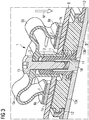
- Figure 3 shows the in Figure 2 Exemplary embodiment of the device 1 with two spring arms 5a, 5b in an assembled state in a longitudinal section through the hollow body 2.
- the components 7a, 7b to be cooled are attached to the carrier plate or printed circuit board 8.
- the cooling body 9 is arranged on a side of the carrier plate 8 which is not equipped at least in the region of the components 7a, 7b or in a cooling region, the cooling body 9 having the fastening body 10 for attaching the device 1 for pressing the components 7a, 7b.
- the carrier plate 8 has, for example, an outlet 11 between the components 7a, 7b, into which the fastening body 10 for the device 1 according to the invention can be introduced — contrary to the mounting direction M of the device.
- the device 1 is introduced in the assembly direction M with the hollow body 2 into the outlet 11 in the carrier plate 8.
- the ends of the spring arms 5a, 5b come to rest with the support surfaces 6a, 6b on the components 7a, 7b to be cooled and the hollow body 2 at least holds the fastening body 10.
- an insulation 14 can be inserted between an inner wall of the hollow body 2 and the fastening body 10. The inner diameter of the hollow body 2 is then configured such that both the fastening body 10 and the insulation 14 can be accommodated.
- a fastening means 15 e.g. screw, rivet
- a fastening means 15 is then introduced through the outlet 3 on the upper side of the hollow body 2 in the mounting direction M and connected to the fastening body 10.
- the contact pressure F is transmitted to the components 7a, 7b via the contact surfaces 6a, 6b at the ends of the spring arms 5a, 5b.
- the components 7a, 7b are pressed after the fixation of the device 1 with the contact force F, which is exerted by the spring arms 5a, 5b, against the carrier plate 8 and thus against the heat sink 9.
- the device 1, in particular the hollow body 2 is configured such that a predetermined minimum voltage distance or a predetermined minimum length for a creepage distance between the contacting or through-contacting of the components 7a, 7b and the metallic fastening body 10 and / or the fastening means 15 is maintained .
Abstract
Die vorliegende Erfindung betrifft allgemein das Gebiet elektrischer und elektronischer Geräte, insbesondere den Bereich der Schaltnetzteile sowie der leistungselektronischen Schaltungen. Im Speziellen bezieht sich die vorliegende Erfindung auf eine Vorrichtung (1) zum Anpressen von auf einer Trägerplatte (8) angebrachten Bauteilen (7a, 7b) an einen Kühlkörper (9). Dabei erfolgt eine Kühlung der Bauelemente (7a, 7b) durch die Trägerplatte bzw. über eine Kontaktierung der Bauelemente (7a, 7b) mit der Trägerplatte (8). Der Kühlkörper (9) ist dazu an einer zumindest in einem Kühlbereich nicht mit Bauelementen (7a, 7b) bestückten Seite bzw. Unterseite der Trägerplatte (8) angeordnet. Die Vorrichtung (1) zum Anpressen von zumindest einem Bauelement (7a, 7b) umfasst dabei zumindest einen Hohlkörper (2) zum Aufnehmen von zumindest einem Befestigungskörper (10) und zumindest einen Federarm (5, 5a, 5b). Dieser zumindest eine Federarm (5, 5a, 5b) ist gekrümmt ausgeführt und weist an seinem Ende eine Auflagefläche (6, 6a, 6b) zum Übertragen einer Anpresskraft (F) auf das zu kühlendes Bauelement (7a, 7b) auf. Die erfindungsgemäße Vorrichtung (1) kann einfach und rasch - insbesondere automatisiert - montiert werden und ermöglicht eine platzsparende Anordnung von zu kühlenden Bauelemente (7a, 7b) insbesondere unter Einhaltung vorgegebener Spannungsabstände bzw. vorgegebener Luft- und Kriechstrecken.The present invention relates generally to the field of electrical and electronic devices, in particular to the area of switching power supplies and power electronic circuits. In particular, the present invention relates to a device (1) for pressing components (7a, 7b) mounted on a carrier plate (8) onto a heat sink (9). The components (7a, 7b) are cooled by the carrier plate or by contacting the components (7a, 7b) with the carrier plate (8). For this purpose, the heat sink (9) is arranged on a side or underside of the carrier plate (8) which is not equipped with components (7a, 7b) at least in one cooling area. The device (1) for pressing on at least one component (7a, 7b) comprises at least one hollow body (2) for receiving at least one fastening body (10) and at least one spring arm (5, 5a, 5b). This at least one spring arm (5, 5a, 5b) is curved and has at its end a bearing surface (6, 6a, 6b) for transmitting a contact pressure (F) to the component (7a, 7b) to be cooled. The device (1) according to the invention can be installed easily and quickly, in particular in an automated manner, and enables a space-saving arrangement of components (7a, 7b) to be cooled, in particular in compliance with predetermined voltage spacings or predetermined air and creepage distances.
Description
Die vorliegende Erfindung betrifft allgemein das Gebiet elektrischer und elektronischer Geräte, insbesondere den Bereich der Schaltnetzteile sowie der leistungselektronischen Schaltungen. Im Speziellen bezieht sich die vorliegende Erfindung auf eine Vorrichtung zum Anpressen von auf einer Trägerplatte angebrachten Bauteilen an einen Kühlkörper. Dabei erfolgt eine Kühlung der Bauelemente über die Trägerplatte bzw. eine Kontaktierung der Bauelemente mit der Trägerplatte. Der Kühlkörper ist dazu an einer zumindest in einem Bereich einer thermischen Kontaktierung bzw. in einem Kühlbereich nicht mit Bauelementen bestückten Seite der Trägerplatte angeordnet.The present invention relates generally to the field of electrical and electronic devices, in particular to the area of switching power supplies and power electronic circuits. In particular, the present invention relates to a device for pressing components mounted on a carrier plate onto a heat sink. The components are cooled via the carrier plate or the components are contacted with the carrier plate. For this purpose, the heat sink is arranged on a side of the carrier plate not equipped with components at least in a region of thermal contacting or in a cooling region.
Geräte, insbesondere elektrische oder elektronische Geräte wie z.B. Schaltnetzteile, leistungselektronische Schaltungen, Steuergeräte, etc. werden heutzutage üblicherweise aus elektrischen Bauelementen und/oder Baugruppen aufgebaut. Die Bauelemente sind dabei auf einer Trägerplatte - einer so genannte Leiterplatte - anbracht, welche einer mechanische Befestigung sowie über so genannte Leiterbahnen einer elektrischen Verbindung der Bauelemente dient. Die Bauelemente können z.B. mittels Anlöten auf Lötflächen oder in Lötaugen, mittels Aufkleben, etc. und bei größeren Bauelementen mittels Verschraubung auf der Leiterplatte befestigt werden.Devices, especially electrical or electronic devices such as Switched-mode power supplies, power electronic circuits, control devices, etc. are usually built up today from electrical components and / or assemblies. The components are attached to a carrier plate - a so-called printed circuit board - which is used for mechanical fastening and for so-called conductor tracks for an electrical connection of the components. The components can e.g. by means of soldering on soldering surfaces or in eyes, by means of gluing, etc. and, in the case of larger components, by means of screws on the circuit board.
Häufig umfasst die Schaltung eines Geräts, insbesondere eines elektrischen Geräts, Halbleiterbauelemente wie z.B. Leistungshalbleiterelemente, etc., von welchen eine meist thermische Verlustenergie - d.h. Wärme - produziert wird. Um beispielsweise eine Beschädigung oder ein Überhitzen des jeweiligen Bauelements oder der Schaltung bzw. eine Funktionsstörung des Geräts durch die Verlustleistung bzw. Wärme zu verhindern, ist es notwendig, diese Verlustleistung produzierenden Bauelemente entsprechend zu kühlen bzw. die produzierte Wärme abzuleiten.Frequently, the switching of a device, in particular an electrical device, comprises semiconductor components such as, for example, power semiconductor elements, etc., from which a mostly thermal energy loss - ie heat - is produced. For example, damage or overheating of the respective To prevent component or the circuit or a malfunction of the device by the power loss or heat, it is necessary to cool these power loss producing components accordingly or to dissipate the heat produced.
Üblicherweise wird dazu die Trägerplatte bzw. Leiterplatte, auf welcher sich die Verlustleistung produzierenden bzw. zu kühlenden Halbleiterbauelemente befinden, mit einem Wärme ableitenden Teil - einem so genannten Kühlkörper - verbunden. Vom Kühlkörper, welcher üblicherweise aus einem gut wärmeleitfähigem Metall, meist Aluminium oder Kupfer besteht, wird eine so genannte Wärmebrücke gebildet, um die entstandene Wärme vom zu kühlenden Bauelement weg zu leiten und z.B. an eine Geräteumgebung abzugeben. Kühlkörper finden beispielsweise in der Leistungselektronik, in Steuergeräten, etc. vor allem zur Kühlung von Leistungshalbleitern (z.B. Leistungsdioden, Leistungstransistoren, etc.) Verwendung.For this purpose, the carrier board or printed circuit board, on which the semiconductor components which produce or are to be cooled are located, is usually connected to a heat-dissipating part - a so-called heat sink. A so-called thermal bridge is formed from the heat sink, which usually consists of a highly thermally conductive metal, usually aluminum or copper, in order to conduct the heat generated away from the component to be cooled and e.g. to be delivered to a device environment. Heat sinks are used, for example, in power electronics, in control units, etc. primarily for cooling power semiconductors (e.g. power diodes, power transistors, etc.).
Bei auf Träger- bzw. Leiterplatten angebrachten Schaltungen kann der Kühlkörper beispielsweise an einer Seite, welche zumindest in einem Bereich von Verlustleistung produzierenden bzw. zu kühlenden Bauelementen - d.h. in einem Kühlbereich - von einer Bestückung mit Bauelementen ausgenommen ist, bzw. an einer Unterseite der Trägerplatte anliegend angeordnet sein. D.h. die von einem Bauelement erzeugte Verlustwärme bzw. Verlustleistung wird dann vom Bauelement durch die Trägerplatte zum Kühlkörper geleitet bzw. die Trägerplatte befindet sich zwischen dem Kühlkörper und einem zu kühlenden Bauelement. Insbesondere bei Träger- bzw. Leiterplatten mit Durchkontaktierungen - d.h. einer vertikalen, elektrischen Verbindung zwischen Leiterbahnebenen der Leiterplatte in Form von innen metallisierten Bohrungen - kann die Ableitung der Wärme auch vom Bauelement über die Durchkontaktierung zum Kühlkörper erfolgen. Bei Schaltungen auf Träger- bzw. Leiterplatten mit Durchkontaktierungen zum Anbringen und Verbinden der Bauelemente werden häufig bei der Montage zur galvanischen Trennung bzw. zur Isolierung zwischen der Trägerplatte bzw. der Durchkontaktierung und dem metallischen Kühlkörper zusätzlich eine elektrisch isolierende Schicht und/oder Isolierungselemente z.B. aus Keramik, Silikongummi oder einem speziellen Kunststoff eingefügt.In the case of circuits mounted on carrier or printed circuit boards, the heat sink can be excluded, for example, on one side, which is at least in a region of heat-producing components or components to be cooled - ie in a cooling region - from being fitted with components, or on an underside of the Carrier plate can be arranged adjacent. That is, the heat loss or power loss generated by a component is then conducted from the component through the carrier plate to the heat sink or the carrier plate is located between the heat sink and a component to be cooled. In particular in the case of carrier or printed circuit boards with plated-through holes - ie a vertical, electrical connection between the conductor track levels of the printed circuit board in the form of internally metallized holes - the heat can also be dissipated from the component via the plated-through holes to the heat sink. In the case of circuits on carrier or printed circuit boards with plated-through holes for attaching and connecting the components, assembly is often used for electrical isolation or for insulation between the carrier plate or the plated-through hole and the metal heat sink, an electrically insulating layer and / or insulating elements, for example made of ceramic, silicone rubber or a special plastic, are also inserted.
Um die Wärmeableitung zu begünstigen, benötigen Kühlkörper eine gute thermische Anbindung an das jeweils zu kühlende Bauelement. Daher ist es notwendig, einen möglichst engen und guten Kontakt zwischen dem Kühlkörper und dem zu kühlenden Bauelement herzustellen. Zum Ausgleich von Unebenheiten z.B. zwischen der Unterseite der Trägerplatte und einer Oberfläche des Kühlkörpers und um einen besseren Wärmeübergang zum Kühlkörper herzustellen, kann vor der Montage z.B. eine dünne Schicht Wärmeleitpaste aufgetragen werden. Bei einer elektrisch isolierenden Montage können die eingefügte elektrisch isolierende Schicht und/oder die Isolierungselemente beispielsweise zum Ausgleichen von Unebenheiten und zur Verbesserung der Wärmeübertragung genutzt werden.In order to promote heat dissipation, heat sinks require a good thermal connection to the component to be cooled. It is therefore necessary to establish as close and good a contact as possible between the heat sink and the component to be cooled. To compensate for unevenness e.g. between the underside of the carrier plate and a surface of the heat sink and in order to produce better heat transfer to the heat sink, e.g. a thin layer of thermal grease is applied. In the case of an electrically insulating assembly, the inserted electrically insulating layer and / or the insulation elements can be used, for example, to compensate for unevenness and to improve the heat transfer.
Um den entsprechend engen und guten thermischen Kontakt zwischen dem zu kühlenden Bauelement und dem Kühlkörper herzustellen, wird das Bauelement üblicherweise auch gegen den Kühlkörper gepresst. Dazu können z.B. Federbleche eingesetzt werden, welche beispielsweise auf den zu kühlenden Bauelementen angeordnet und mittels Schrauben oder Klammern befestigt werden. Die Federbleche bewirken dann z.B. eine Anpresskraft, welche die Bauelemente gegen die Trägerplatte und damit gegen den an der Unterseite der Trägerplatte angeordneten Kühlkörper presst. Die Verwendung von Federblechen zum Anpressen von Bauelementen weist allerdings den Nachteil auf, dass eine Montage meist manuell durchgeführt werden muss und mit relativ großem Aufwand verbunden ist.In order to produce the correspondingly close and good thermal contact between the component to be cooled and the heat sink, the component is usually also pressed against the heat sink. For this, e.g. Spring plates are used, which are arranged, for example, on the components to be cooled and fastened by means of screws or clips. The spring plates then cause e.g. a contact pressure which presses the components against the carrier plate and thus against the heat sink arranged on the underside of the carrier plate. However, the use of spring plates for pressing components has the disadvantage that assembly usually has to be carried out manually and is relatively expensive.
Vor allem bei elektrischen Geräten, wie z.B. Schaltnetzteilen oder bei leistungselektronischen Schaltungen sind weiterhin üblicherweise vorgegebene Spannungsabstände bzw. Mindestabstände für so genannte Luft- und Kriechstrecken zwischen leitenden Teilen der Schaltung zu berücksichtigen. D.h. es sind z.B. aus Sicherheits- und/oder funktionstechnischen Gründen Mindestabstände zwischen z.B. Leiterbahnen, Bauelementkontaktierungen und weiteren leitenden Teilen wie z.B. Kühlkörpern, Befestigungsmitteln und auch Federblechen zum Anpressen von Bauelementen einzuhalten, um beispielsweise Personen oder Geräte vor Auswirkungen von elektrischer Spannung und/oder Strom bestmöglich zu schützen. Derartige Mindestabstände sind beispielsweise in Normen wie z.B. in der
Der Erfindung liegt daher die Aufgabe zugrunde, eine Vorrichtung zum Anpressen für Bauelemente an einen Kühlkörper anzugeben, welche einfach und kostengünstig mit geringem Zeitaufwand montierbar ist und eine platzsparende Anordnung der Bauelemente unter Einhaltung von vorgegebenen Spannungsabständen ermöglicht.The invention is therefore based on the object of specifying a device for pressing components onto a heat sink, which is simple and inexpensive to assemble with little expenditure of time and enables a space-saving arrangement of the components while maintaining predetermined voltage spacings.
Diese Aufgabe wird durch eine Vorrichtung der eingangs beschriebenen Art mit den Merkmalen des unabhängigen Anspruchs gelöst. Vorteilhafte Ausführungsformen der vorliegenden Erfindung sind in den abhängigen Ansprüchen beschrieben. Erfindungsgemäß erfolgt die Lösung der Aufgabe durch eine Vorrichtung der eingangs beschriebenen Art zum Anpressen von Bauelementen, welche auf einer Trägerplatte angeordnet und angebracht sind, an einen Kühlkörper. Dabei erfolgt eine Kühlung der Bauelemente über die Trägerplatte und/oder eine Kontaktierung der Bauelemente. Der Kühlkörper ist dazu an einer im Bereich der zu kühlenden Bauelemente nicht mit Bauelementen bestückten Seite bzw. Unterseite der Trägerplatte angeordnet. Dazu umfasst die erfindungsgemäße Vorrichtung zumindest einen Hohlkörper und zumindest einen Federarm. Der Hohlkörper ist zumindest zum Aufnehmen eines Befestigungskörpers eingerichtet, welcher beispielsweise direkt auf dem Kühlkörper angebracht sein kann und mit welchem die Vorrichtung befestigbar ist. Weiterhin weist die Vorrichtung einen Federarm auf, welcher gekrümmt ist und ein Ende des Federarms eine Auflagefläche zum Übertragen einer Anpresskraft auf ein zu kühlendes Bauelement aufweist.This object is achieved by a device of the type described in the introduction with the features of the independent claim. Advantageous embodiments of the present invention are described in the dependent claims. According to the invention, the object is achieved by a device of the type described at the outset for pressing components which are arranged and attached to a carrier plate to a heat sink. The components are cooled via the carrier plate and / or the components are contacted. For this purpose, the heat sink is arranged on a side or underside of the carrier plate which is not equipped with components in the region of the components to be cooled. For this purpose, the device according to the invention comprises at least one hollow body and at least one spring arm. The hollow body is set up at least to receive a fastening body, which can be attached directly to the heat sink, for example, and with which the device can be fastened. Furthermore, the device has a spring arm, which is curved and one end of the spring arm has a support surface for transmitting a contact pressure to a component to be cooled.
Der Hauptaspekt der erfindungsgemäß vorgeschlagenen Lösung besteht darin, dass die Vorrichtung einfach und zeitsparend - in einer relativ kurzen Montagezeit - auf der Trägerplatte bzw. bei der Fertigung bzw. Montage der Schaltung bzw. des elektrischen Gerätes angebracht werden kann. Insbesondere ist die Vorrichtung für eine automatisierte Montage geeignet. Weiterhin ermöglicht die Vorrichtung - vor allem durch die Ausgestaltung des zumindest einen Federarm - eine platzsparende Anordnung der Bauelemente auf der Trägerplatte und damit eine platzsparende Ausgestaltung der Schaltung. Insbesondere bei elektrischen Geräten, wie z.B. Schaltnetzteilen, etc. und leistungselektronischen Schaltungen ermöglicht die Vorrichtung - insbesondere durch den Hohlkörper - trotz platzsparender Anordnung der zu kühlenden Bauelemente eine Einhaltung der vorgegebenen Spannungsabstände bzw. von vorgegebenen Mindestabständen für Luft- und Kriechstrecken zwischen einer Bauelementkontaktierung und dem Kühlkörper.The main aspect of the solution proposed according to the invention is that the device can be attached simply and in a time-saving manner - in a relatively short assembly time - to the carrier plate or during the manufacture or assembly of the circuit or of the electrical device. In particular, the device is suitable for automated assembly. Furthermore, the device enables a space-saving arrangement of the components on the carrier plate, and thus a space-saving configuration of the circuit, especially due to the configuration of the at least one spring arm. Especially with electrical devices, such as Switching power supplies, etc. and power electronic circuits enable the device - in particular through the hollow body - in spite of the space-saving arrangement of the components to be cooled to adhere to the specified voltage distances or to the specified minimum distances for air and creepage distances between a component contact and the heat sink.
Insbesondere zum Einhalten dieser vorgegebenen Mindestabstände für Luft- und Kriechstrecken sowie aus Betriebssicherheitsgründen ist es von Vorteil, wenn die Vorrichtung derart ausgestaltet ist, dass in einem montierten Zustand ein vorgegebener Mindestspannungsabstand bzw. ein vorgegebener Mindestabstand für die Kriechstrecke zwischen einer Kontaktierung des zu kühlenden Bauelements und dem Befestigungskörper und/oder einem Befestigungsmittel zum Fixieren der Vorrichtung an der Trägerplatte eingehalten wird. Als Kriechstrecke wird dabei eine kürzeste Entfernung entlang einer Oberfläche eines festen Isolierstoffs zwischen zwei leitenden Teilen wie z.B. Leiterbahnen auf der Trägerplatte bzw. einer Kontaktierung oder Durchkontaktierung eines Bauelements und z.B. eines Befestigungskörpers bzw. eines Befestigungsmittels aus Metall.In particular to maintain these specified minimum clearances for clearances and creepage distances and for operational safety reasons it is advantageous if the device is designed such that, in an assembled state, a predetermined minimum voltage distance or a predetermined minimum distance for the creepage distance between contacting the component to be cooled and the fastening body and / or a fastening means for fixing the device to the carrier plate is observed. The shortest distance along a surface of a solid insulating material between two conductive parts such as, for example, conductor tracks on the carrier plate or a contacting or through-contacting of a component and, for example, a fastening body or a fastening means made of metal is used as the creepage distance.
Idealerweise ist zumindest der Federarm zumindest viertelkreisförmig gekrümmt ausgestaltet. Durch diese Ausgestaltung kann sehr einfach die Anpresskraft über die Auflagefläche an das Bauelement übertragen werden. Die Krümmung des Federarms hat dabei die Aufgabe einen ausreichenden Federweg bereit zu stellen und dabei zu ermöglichen, dass zu kühlenden Bauelemente so nahe aneinander bzw. an spannungsführende Teile (z.B. Leiterbahnen, etc.) unter Einhaltung vorgegebener Spannungs- bzw. Sicherheitsabstände angeordnet werden können. Der zumindest eine Federarm weist außerdem eine relativ hohe mechanische Belastbarkeit auf und ist platzsparend.Ideally, at least the spring arm is designed to be at least quarter-circle curved. With this configuration, the contact pressure can be very easily transmitted to the component via the contact surface. The curvature of the spring arm has the task of providing sufficient spring travel and thereby making it possible for components to be cooled to be arranged so close to one another or to live parts (e.g. conductor tracks, etc.) while observing predetermined voltage or safety distances. The at least one spring arm also has a relatively high mechanical strength and is space-saving.
Besonders günstig hat sich eine Omega-ähnlich gekrümmte Ausgestaltung des Federarms erwiesen, durch welche sehr geringe Abstände von zu kühlenden Bauelementen zueinander und/oder von spannungsführenden Teilen bei gleichzeitiger Einhaltung der vorgegebenen Spannungsabständen sowie eine gute Anpressung zu kühlender Bauelemente ermöglicht werden. Weiterhin ist die Vorrichtung aufgrund eines Omega-förmigen Federarms, aber vor allem bei zwei oder mehr Omega-förmigen Federarmen bei einer automatisierten Montage z.B. mittels eines Roboterarms leicht greifbar und platzierbar.An omega-like curved configuration of the spring arm has proven to be particularly favorable, by means of which very short distances from components to be cooled to one another and / or from live parts while maintaining the specified voltage spacings and good pressure on components to be cooled are made possible. Furthermore, the device is easy to grasp and place due to an omega-shaped spring arm, but especially with two or more omega-shaped spring arms in an automated assembly, for example by means of a robot arm.
Der Federarm kann idealerweise einen kreisförmigen oder quadratischen oder rechteckigen Querschnitt aufweisen. Dadurch kann die Anpresskraft beispielsweise über eine kreisförmige oder quadratische Fläche - eher konzentriert - oder über eine rechteckige Fläche verteilt an das zu kühlende Bauelement übertragen werden bzw. die Auflagefläche z.B. an eine Bauelementgröße angepasst werden.The spring arm can ideally have a circular or square or rectangular cross section. As a result, the contact pressure can be transferred to the component to be cooled, for example over a circular or square surface - more concentrated - or distributed over a rectangular surface, or the contact surface e.g. can be adapted to a component size.
Bei einer vorteilhaften Ausgestaltung der erfindungsgemäßen Vorrichtung ist weiterhin vorgesehen, dass die Auflagefläche am Ende des zumindest einen Federarms als polygonförmige Abplattung ausgeführt ist. Dadurch wird die Anpresskraft gleichmäßig auf das zu kühlende bzw. anzupressende Bauelement übertragen. Das Bauelement wird dadurch auf einfache Weise flächig gegen den Kühlkörper gedrückt und kann beispielsweise über seine gesamte Fläche gekühlt werden.In an advantageous embodiment of the device according to the invention it is further provided that the bearing surface at the end of the at least one spring arm is designed as a polygonal flattening. As a result, the contact pressure is evenly transmitted to the component to be cooled or pressed. As a result, the component is simply pressed flat against the heat sink and can be cooled, for example, over its entire surface.
Es ist weiterhin günstig, wenn der Hohlkörper der erfindungsgemäßen Vorrichtung derart ausgestaltet ist, dass ein Befestigungsmittel einbringbar ist, welches für eine Montage mit dem Befestigungskörper lösbar oder unlösbar verbindbar ist. Der Hohlkörper kann dazu eine Bohrung aufweisen, in welcher das Befestigungsmittel (z.B. Schraube, Niete) eingebracht werden kann. Das Befestigungsmittel kann dann bei der Montage der erfindungsgemäßen Vorrichtung mit dem im Inneren des Hohlkörpers befindlichen Befestigungskörper, der z.B. auf dem Kühlkörper angebracht ist, verbunden werden.It is furthermore favorable if the hollow body of the device according to the invention is designed in such a way that a fastening means can be introduced which can be detachably or non-releasably connected to the fastening body for assembly. For this purpose, the hollow body can have a bore in which the fastening means (e.g. screw, rivet) can be introduced. The fastening means can then be used in the assembly of the device according to the invention with the fastening body located inside the hollow body, which e.g. attached to the heat sink.
Bei einer zweckmäßigen Ausgestaltung der erfindungsgemäßen Vorrichtung ist ein Innendurchmesser des Hohlkörpers derart ausgestaltet ist, dass zwischen einer Innenwand des Hohlkörpers und dem Befestigungskörper eine Isolierung einfügbar ist.In an expedient embodiment of the device according to the invention, an inner diameter of the hollow body is configured such that insulation can be inserted between an inner wall of the hollow body and the fastening body.
Weiterhin weist der Hohlkörper der erfindungsgemäßen Vorrichtung einen Verdrehschutz auf, durch welchen auf einfache Weise ein Verdrehen der Vorrichtung beim Platzieren und Befestigen verhindert wird. Damit wird vor allem eine automatisierte Montage erleichtert und vereinfacht.Furthermore, the hollow body of the device according to the invention has an anti-twist device, by means of which twisting of the device during placement and fastening is simple is prevented. In particular, automated assembly is facilitated and simplified.
Es ist zweckmäßig, wenn die Vorrichtung einteilig aus elastischem Material - idealerweise als Kunststoffspritzgussteil - ausgeführt ist. Damit wird die Montage verkürzt und vereinfacht, da nur ein Teil zum Anpressen von zumindest einem Bauelement angebracht werden muss. Dadurch werden die Montagekosten reduziert und es können die Geräte bzw. Schaltungen platzsparender, rascher und kostengünstiger hergestellt werden. Außerdem führt die Verwendung eines elastischen Material - vor allem Kunststoff - für die Vorrichtung beim Einsatz in einem elektrischen Geräte zu keinen direkten EMV-Auswirkungen - d.h. es treten damit durch die Vorrichtung keine ungewollten elektrischen und/oder elektromagnetischen Effekte auf, welche die Funktionsweise des elektrischen Geräts stören könnten. Weiterhin ist insbesondere bei Verwendung von Hochleistungskunststoffen (z.B. Polythermid bzw. PEI, Polyamidimid bzw. PAI), welche eine hohe Temperaturbeständigkeit aufweisen, über einen weiten Temperaturbereich für eine federnde Wirkung der Vorrichtung gesorgt - d.h. durch die Vorrichtung wird das jeweilige zu kühlende Bauelement mit dem entsprechenden Anpressdruck über einen weiten Temperaturbereich gegen den Kühlkörper gedrückt.It is useful if the device is made in one piece from elastic material - ideally as a plastic injection molded part. This shortens and simplifies assembly, since only one part has to be attached for pressing on at least one component. As a result, the assembly costs are reduced and the devices or circuits can be manufactured in a more space-saving, faster and cheaper manner. In addition, the use of an elastic material - especially plastic - for the device when used in an electrical device does not lead to any direct EMC effects - i.e. there are therefore no unwanted electrical and / or electromagnetic effects caused by the device which could interfere with the functioning of the electrical device. Furthermore, especially when using high-performance plastics (e.g. polythermide or PEI, polyamideimide or PAI), which have a high temperature resistance, a resilient effect of the device is ensured over a wide temperature range - i.e. the device presses the respective component to be cooled against the heat sink with the corresponding contact pressure over a wide temperature range.
Die Erfindung wird nachfolgend in beispielhafter Weise anhand der beigefügten Figuren erläutert. Dabei zeigen:
- Figur 1
- schematisch eine beispielhafte Ausführungsform der erfindungsgemäßen Vorrichtung zum Anpressen von Bauelementen an einen Kühlkörper
Figur 2- schematisch eine weitere, beispielhafte Ausführungsform der erfindungsgemäßen Vorrichtung zum Anpressen von Bauelementen an einen Kühlkörper mit zwei Federarmen
Figur 3- schematisch und beispielshaft eine Ausführungsform der erfindungsgemäßen Vorrichtung zum Anpressen von Bauelementen in einem montierten Zustand
- Figure 1
- schematically an exemplary embodiment of the device according to the invention for pressing components onto a heat sink
- Figure 2
- schematically shows another exemplary embodiment of the device according to the invention for pressing components onto a heat sink with two spring arms
- Figure 3
- schematically and by way of example an embodiment of the device according to the invention for pressing components in an assembled state
Die Vorrichtung 1 umfasst einen Hohlkörper 2, welcher beispielsweise als Hohlzylinder ausgeführt sein kann. Alternativ kann der Hohlkörper 2 auch einen quadratischen oder rechteckigen Querschnitt aufweisen. Der Hohlkörper ist zum Aufnehmen zumindest eines Befestigungskörpers 10 - wie anhand von
Weiterhin weist der Hohlkörper 2 auf einer in Montagerichtung M oberen Seite einen Auslass 3 auf. In diesen Auslass 3 kann bei der Montage ein Befestigungsmittel 15 (z.B. eine Schraube oder eine Niete) eingebracht werden, welches mit dem Befestigungskörper 10 lösbar oder unlösbar verbindbar ist. Durch das Einbringen des Befestigungsmittels 15 bzw. durch die Verbindung zwischen Befestigungsmittel 15 und Befestigungskörper 10 wird die Vorrichtung 1 befestigt und das Bauelement 7a, 7b durch eine Anpresskraft F gegen die Trägerplatte 8 bzw. den Kühlkörper 9 gepresst. Für ein einfaches Platzieren und Montieren der Vorrichtung 1 weist der Hohlkörper 2 einen Verdrehschutz 4 auf, welcher über ein in Montagerichtung M unteres Ende des Hohlkörpers hinausragt und z.B. in entsprechende Auslässe der Trägerplatte 8 eingreifen kann.Furthermore, the
Weiterhin weist die Vorrichtung 1 einen Federarm 5 auf, welcher gekrümmt ausgestaltet ist. Der in
In
Die in
Die in
Die zu kühlenden Bauelemente 7a, 7b sind auf der Trägerplatte bzw. Leiterplatte 8 angebracht. An einer zumindest im Bereich der zu kühlenden Bauelemente 7a, 7b bzw. in einem Kühlbereich nicht bestückten Seite der Trägerplatte 8 ist der Kühlkörper 9 angeordnet, wobei der Kühlkörper 9 den Befestigungskörper 10 zum Anbringen der Vorrichtung 1 zum Anpressen der Bauelemente 7a, 7b aufweist. Die Trägerplatte 8 weist z.B. zwischen den Bauelementen 7a, 7b einen Auslass 11 auf, in welchen der Befestigungskörper 10 für die erfindungsgemäße Vorrichtung 1 - entgegen der Montagerichtung M der Vorrichtung - einbringbar ist. Für eine galvanische Trennung der Trägerplatte 8 bzw. der Kontakte, insbesondere einer Durchkontaktierungen, der Bauelemente 7a, 7b vom Kühlkörper 9, welcher aus Metall, insbesondere Aluminium, ausgeführt sein kann, können zwischen der im Kühlbereich nicht bestückten Seite bzw. Unterseite der Trägerplatte 8 und dem Kühlkörper 9 eine Isolierungsschicht 12 bzw. unterhalb der Bauelemente 7a, 7b Isolierelemente 13a, 13b angeordnet sein.The
Bei einer Montage wird die Vorrichtung 1 in der Montagerichtung M mit dem Hohlkörper 2 in den Auslass 11 in der Trägerplatte 8 eingebracht. Dabei kommen die Enden der Federarme 5a, 5b mit den Auflageflächen 6a, 6b auf den zu kühlenden Bauelementen 7a, 7b zum Liegen und der Hohlkörper 2 nimmt zumindest den Befestigungskörper 10 auf. Weiterhin kann zwischen einer Innenwand des Hohlkörpers 2 und dem Befestigungskörper 10 noch eine Isolierung 14 eingefügt sein. Der Innendurchmesser des Hohlkörpers 2 ist dann derart ausgestaltet, dass sowohl der Befestigungskörper 10 als auch die Isolierung 14 aufgenommen werden kann.During assembly, the device 1 is introduced in the assembly direction M with the
Durch den Auslass 3 an der oberen Seite des Hohlkörpers 2 wird dann in Montagerichtung M ein Befestigungsmittel 15 (z.B. Schraube, Niete) eingebracht und mit dem Befestigungskörper 10 verbunden. Durch diese Verbindung wird über die Auflageflächen 6a, 6b an den Enden der Federarme 5a, 5b die Anpresskraft F auf die Bauelemente 7a, 7b übertragen. D.h. die Bauelemente 7a, 7b werden nach Fixierung der Vorrichtung 1 mit der Anpresskraft F, welche von den Federarmen 5a, 5b ausgeübt wird, gegen die Trägerplatte 8 und damit gegen den Kühlkörper 9 gepresst.A fastening means 15 (e.g. screw, rivet) is then introduced through the
Weiterhin ist die Vorrichtung 1, insbesondere der Hohlkörper 2, derart ausgestaltet, dass ein vorgegebener Mindestspannungsabstand bzw. eine vorgegebene Mindestlänge für eine Kriechstrecke zwischen der Kontaktierung bzw. Durchkontaktierung der Bauelemente 7a, 7b und dem metallischen Befestigungskörper 10 und/oder dem Befestigungsmittel 15 eingehalten wird.Furthermore, the device 1, in particular the
- 11
- Vorrichtung zum Anpressen von BauelementenDevice for pressing components
- 22nd
- HohlkörperHollow body
- 33rd
- Auslass zum Einbringen eines BefestigungsmittelsOutlet for inserting a fastener
- 44th
- VerdrehschutzProtection against rotation
- 5, 5a, 5b5, 5a, 5b
- FederarmSpring arm
- 6, 6a, 6b6, 6a, 6b
- AuflageflächeContact surface
- 7a, 7b7a, 7b
- BauelementeComponents
- 88th
- Trägerplatten bzw. LeiterplattenCarrier boards or printed circuit boards
- 99
- KühlkörperHeatsink
- 1010th
- BefestigungskörperFastening body
- 1111
- Auslass in der Träger- bzw. LeiterplatteOutlet in the carrier or printed circuit board
- 1212th
- IsolierungsschichtInsulation layer
- 13a, 13b13a, 13b
- IsolierelementeInsulating elements
- 1414
- Isolierunginsulation
- 1515
- BefestigungsmittelFasteners
- FF
- AnpresskraftContact pressure
- MM
- MontagerichtungInstallation direction
Claims (10)
Priority Applications (4)
| Application Number | Priority Date | Filing Date | Title |
|---|---|---|---|
| EP18196828.0A EP3629686A1 (en) | 2018-09-26 | 2018-09-26 | Device for pressing of components |
| CN201980063581.4A CN112740843A (en) | 2018-09-26 | 2019-09-12 | Device for pressing a component |
| US17/279,704 US11937404B2 (en) | 2018-09-26 | 2019-09-12 | Pressing device |
| PCT/EP2019/074364 WO2020064355A1 (en) | 2018-09-26 | 2019-09-12 | Device for pressing components |
Applications Claiming Priority (1)
| Application Number | Priority Date | Filing Date | Title |
|---|---|---|---|
| EP18196828.0A EP3629686A1 (en) | 2018-09-26 | 2018-09-26 | Device for pressing of components |
Publications (1)
| Publication Number | Publication Date |
|---|---|
| EP3629686A1 true EP3629686A1 (en) | 2020-04-01 |
Family
ID=63685683
Family Applications (1)
| Application Number | Title | Priority Date | Filing Date |
|---|---|---|---|
| EP18196828.0A Pending EP3629686A1 (en) | 2018-09-26 | 2018-09-26 | Device for pressing of components |
Country Status (4)
| Country | Link |
|---|---|
| US (1) | US11937404B2 (en) |
| EP (1) | EP3629686A1 (en) |
| CN (1) | CN112740843A (en) |
| WO (1) | WO2020064355A1 (en) |
Citations (3)
| Publication number | Priority date | Publication date | Assignee | Title |
|---|---|---|---|---|
| US20090168360A1 (en) * | 2008-01-02 | 2009-07-02 | Harman International Industries, Incorporated | Clamp for electrical devices |
| US20120218712A1 (en) * | 2011-02-28 | 2012-08-30 | Tdk Corporation | Spring fixture for electronic component and heat sink structure |
| EP3208843A1 (en) * | 2016-02-17 | 2017-08-23 | ELinter AG | Retaining clip |
Family Cites Families (6)
| Publication number | Priority date | Publication date | Assignee | Title |
|---|---|---|---|---|
| US4922601A (en) * | 1987-11-02 | 1990-05-08 | Chrysler Corporation | Method of making a heat sink for electrical components |
| FR2798814B1 (en) * | 1999-09-22 | 2001-11-16 | Valeo Vision | IMPROVEMENTS IN ELECTRONIC THERMAL DRAIN ASSEMBLIES, IN PARTICULAR FOR A MOTOR VEHICLE PROJECTOR DISCHARGE LAMP CONTROL MODULE |
| CN107035912A (en) * | 2011-09-22 | 2017-08-11 | 株式会社不二工机 | Valve gear |
| DE102011084365A1 (en) * | 2011-10-12 | 2013-04-18 | Osram Gmbh | LED module with a heat sink |
| EP3174375B1 (en) | 2015-09-07 | 2019-06-26 | Hak Sik Joo | Complex sheet for absorbing/extinguishing and shielding electromagnetic waves and highly dissipating heat from electronic device and manufacturing method therefor |
| JP6898162B2 (en) * | 2017-06-23 | 2021-07-07 | 矢崎総業株式会社 | Fixed structure of electronic components |
-
2018
- 2018-09-26 EP EP18196828.0A patent/EP3629686A1/en active Pending
-
2019
- 2019-09-12 CN CN201980063581.4A patent/CN112740843A/en active Pending
- 2019-09-12 WO PCT/EP2019/074364 patent/WO2020064355A1/en active Application Filing
- 2019-09-12 US US17/279,704 patent/US11937404B2/en active Active
Patent Citations (3)
| Publication number | Priority date | Publication date | Assignee | Title |
|---|---|---|---|---|
| US20090168360A1 (en) * | 2008-01-02 | 2009-07-02 | Harman International Industries, Incorporated | Clamp for electrical devices |
| US20120218712A1 (en) * | 2011-02-28 | 2012-08-30 | Tdk Corporation | Spring fixture for electronic component and heat sink structure |
| EP3208843A1 (en) * | 2016-02-17 | 2017-08-23 | ELinter AG | Retaining clip |
Also Published As
| Publication number | Publication date |
|---|---|
| WO2020064355A1 (en) | 2020-04-02 |
| CN112740843A (en) | 2021-04-30 |
| US20210400839A1 (en) | 2021-12-23 |
| US11937404B2 (en) | 2024-03-19 |
Similar Documents
| Publication | Publication Date | Title |
|---|---|---|
| EP2043412B1 (en) | Conductor rail with heat conduction | |
| DE102015111204B4 (en) | Power electronic module with load connection elements | |
| DE102006008807B4 (en) | Arrangement with a power semiconductor module and a cooling component | |
| DE112006002302T5 (en) | Integrated thermal and electrical connection system for power equipment | |
| EP3763177B1 (en) | Electrical appliance arrangement having an electrical appliance which can be fastened to a support element, in particular a wall | |
| DE102015103096A1 (en) | Cooling device and cooling arrangement with the cooling device | |
| DE102016112777A1 (en) | Power semiconductor device | |
| DE19518522C2 (en) | Control device for a motor vehicle | |
| DE102015219851B4 (en) | control unit | |
| EP1672692B1 (en) | Power semiconductor module | |
| DE202018102388U1 (en) | circuitry | |
| DE102016115572B4 (en) | Power semiconductor device system having a first and a second power semiconductor device | |
| EP2716145A1 (en) | Printed circuit board for electric components, and printed circuit board system | |
| EP3841854B1 (en) | Method for mounting an electrical device | |
| DE102014101024B3 (en) | Power semiconductor device | |
| DE102009060123B4 (en) | Electrical circuit comprising at least one printed circuit board and a number of provided with Bauteilekontaktierungen electrical components | |
| DE102018124186B4 (en) | Electronic device and arrangement of such on a mounting rail | |
| DE102006032436A1 (en) | Device for arrangement of electronic element on printed circuit board, has support element, electro-technical element, which is arranged on support element, and cover that is provided with electro-technical element for support element | |
| EP3629686A1 (en) | Device for pressing of components | |
| DE19603224A1 (en) | Power semiconductor mechanical apparatus for e.g. power switch or rectifier | |
| DE102014116058B3 (en) | Power semiconductor device | |
| EP3200225A2 (en) | Electronic module with a power semiconductor assembly | |
| DE102006032441A1 (en) | Device has printed circuit board, module which comprising electro-technical element and mechanically loadable electrical contact element on side, and module is electrically connected on side | |
| EP1864557B1 (en) | Method for producing an electronic appliance, and corresponding electronic appliance | |
| DE202013010288U1 (en) | Frequency converter with DC link capacitor |
Legal Events
| Date | Code | Title | Description |
|---|---|---|---|
| PUAI | Public reference made under article 153(3) epc to a published international application that has entered the european phase |
Free format text: ORIGINAL CODE: 0009012 |
|
| STAA | Information on the status of an ep patent application or granted ep patent |
Free format text: STATUS: THE APPLICATION HAS BEEN PUBLISHED |
|
| AK | Designated contracting states |
Kind code of ref document: A1 Designated state(s): AL AT BE BG CH CY CZ DE DK EE ES FI FR GB GR HR HU IE IS IT LI LT LU LV MC MK MT NL NO PL PT RO RS SE SI SK SM TR |
|
| AX | Request for extension of the european patent |
Extension state: BA ME |
|
| STAA | Information on the status of an ep patent application or granted ep patent |
Free format text: STATUS: REQUEST FOR EXAMINATION WAS MADE |
|
| 17P | Request for examination filed |
Effective date: 20200928 |
|
| RBV | Designated contracting states (corrected) |
Designated state(s): AL AT BE BG CH CY CZ DE DK EE ES FI FR GB GR HR HU IE IS IT LI LT LU LV MC MK MT NL NO PL PT RO RS SE SI SK SM TR |
|
| STAA | Information on the status of an ep patent application or granted ep patent |
Free format text: STATUS: EXAMINATION IS IN PROGRESS |
|
| 17Q | First examination report despatched |
Effective date: 20220225 |