EP3629114B1 - Système d'automatisation industrielle haute disponibilité doté d'organes de commande d'automatisation industrielle primaire et secondaire et procédé de communication d'informations par celui-ci - Google Patents
Système d'automatisation industrielle haute disponibilité doté d'organes de commande d'automatisation industrielle primaire et secondaire et procédé de communication d'informations par celui-ci Download PDFInfo
- Publication number
- EP3629114B1 EP3629114B1 EP19199157.9A EP19199157A EP3629114B1 EP 3629114 B1 EP3629114 B1 EP 3629114B1 EP 19199157 A EP19199157 A EP 19199157A EP 3629114 B1 EP3629114 B1 EP 3629114B1
- Authority
- EP
- European Patent Office
- Prior art keywords
- industrial automation
- controller
- automation controller
- primary
- industrial
- Prior art date
- Legal status (The legal status is an assumption and is not a legal conclusion. Google has not performed a legal analysis and makes no representation as to the accuracy of the status listed.)
- Active
Links
- 238000000034 method Methods 0.000 title claims description 11
- 238000004891 communication Methods 0.000 claims description 18
- 230000015654 memory Effects 0.000 description 20
- 238000012795 verification Methods 0.000 description 16
- 238000010586 diagram Methods 0.000 description 6
- 230000008569 process Effects 0.000 description 6
- 238000012545 processing Methods 0.000 description 6
- 238000012546 transfer Methods 0.000 description 6
- 230000001360 synchronised effect Effects 0.000 description 5
- 230000006870 function Effects 0.000 description 3
- 230000008859 change Effects 0.000 description 2
- 230000007257 malfunction Effects 0.000 description 2
- 238000004886 process control Methods 0.000 description 2
- 230000009471 action Effects 0.000 description 1
- 230000005540 biological transmission Effects 0.000 description 1
- 239000000872 buffer Substances 0.000 description 1
- 239000000356 contaminant Substances 0.000 description 1
- 230000008878 coupling Effects 0.000 description 1
- 238000010168 coupling process Methods 0.000 description 1
- 238000005859 coupling reaction Methods 0.000 description 1
- 230000003111 delayed effect Effects 0.000 description 1
- 230000001419 dependent effect Effects 0.000 description 1
- 230000007613 environmental effect Effects 0.000 description 1
- 238000004519 manufacturing process Methods 0.000 description 1
- 238000012986 modification Methods 0.000 description 1
- 230000004048 modification Effects 0.000 description 1
- 238000012544 monitoring process Methods 0.000 description 1
- 230000000737 periodic effect Effects 0.000 description 1
- 230000035939 shock Effects 0.000 description 1
Images


Classifications
-
- G—PHYSICS
- G05—CONTROLLING; REGULATING
- G05B—CONTROL OR REGULATING SYSTEMS IN GENERAL; FUNCTIONAL ELEMENTS OF SUCH SYSTEMS; MONITORING OR TESTING ARRANGEMENTS FOR SUCH SYSTEMS OR ELEMENTS
- G05B19/00—Programme-control systems
- G05B19/02—Programme-control systems electric
- G05B19/418—Total factory control, i.e. centrally controlling a plurality of machines, e.g. direct or distributed numerical control [DNC], flexible manufacturing systems [FMS], integrated manufacturing systems [IMS] or computer integrated manufacturing [CIM]
- G05B19/4184—Total factory control, i.e. centrally controlling a plurality of machines, e.g. direct or distributed numerical control [DNC], flexible manufacturing systems [FMS], integrated manufacturing systems [IMS] or computer integrated manufacturing [CIM] characterised by fault tolerance, reliability of production system
-
- G—PHYSICS
- G05—CONTROLLING; REGULATING
- G05B—CONTROL OR REGULATING SYSTEMS IN GENERAL; FUNCTIONAL ELEMENTS OF SUCH SYSTEMS; MONITORING OR TESTING ARRANGEMENTS FOR SUCH SYSTEMS OR ELEMENTS
- G05B19/00—Programme-control systems
- G05B19/02—Programme-control systems electric
- G05B19/04—Programme control other than numerical control, i.e. in sequence controllers or logic controllers
- G05B19/05—Programmable logic controllers, e.g. simulating logic interconnections of signals according to ladder diagrams or function charts
- G05B19/052—Linking several PLC's
-
- G—PHYSICS
- G05—CONTROLLING; REGULATING
- G05B—CONTROL OR REGULATING SYSTEMS IN GENERAL; FUNCTIONAL ELEMENTS OF SUCH SYSTEMS; MONITORING OR TESTING ARRANGEMENTS FOR SUCH SYSTEMS OR ELEMENTS
- G05B9/00—Safety arrangements
- G05B9/02—Safety arrangements electric
- G05B9/03—Safety arrangements electric with multiple-channel loop, i.e. redundant control systems
-
- G—PHYSICS
- G05—CONTROLLING; REGULATING
- G05B—CONTROL OR REGULATING SYSTEMS IN GENERAL; FUNCTIONAL ELEMENTS OF SUCH SYSTEMS; MONITORING OR TESTING ARRANGEMENTS FOR SUCH SYSTEMS OR ELEMENTS
- G05B15/00—Systems controlled by a computer
- G05B15/02—Systems controlled by a computer electric
-
- G—PHYSICS
- G05—CONTROLLING; REGULATING
- G05B—CONTROL OR REGULATING SYSTEMS IN GENERAL; FUNCTIONAL ELEMENTS OF SUCH SYSTEMS; MONITORING OR TESTING ARRANGEMENTS FOR SUCH SYSTEMS OR ELEMENTS
- G05B19/00—Programme-control systems
- G05B19/02—Programme-control systems electric
- G05B19/418—Total factory control, i.e. centrally controlling a plurality of machines, e.g. direct or distributed numerical control [DNC], flexible manufacturing systems [FMS], integrated manufacturing systems [IMS] or computer integrated manufacturing [CIM]
- G05B19/4185—Total factory control, i.e. centrally controlling a plurality of machines, e.g. direct or distributed numerical control [DNC], flexible manufacturing systems [FMS], integrated manufacturing systems [IMS] or computer integrated manufacturing [CIM] characterised by the network communication
-
- G—PHYSICS
- G06—COMPUTING; CALCULATING OR COUNTING
- G06F—ELECTRIC DIGITAL DATA PROCESSING
- G06F13/00—Interconnection of, or transfer of information or other signals between, memories, input/output devices or central processing units
- G06F13/38—Information transfer, e.g. on bus
- G06F13/42—Bus transfer protocol, e.g. handshake; Synchronisation
- G06F13/4204—Bus transfer protocol, e.g. handshake; Synchronisation on a parallel bus
- G06F13/4221—Bus transfer protocol, e.g. handshake; Synchronisation on a parallel bus being an input/output bus, e.g. ISA bus, EISA bus, PCI bus, SCSI bus
- G06F13/423—Bus transfer protocol, e.g. handshake; Synchronisation on a parallel bus being an input/output bus, e.g. ISA bus, EISA bus, PCI bus, SCSI bus with synchronous protocol
-
- G—PHYSICS
- G06—COMPUTING; CALCULATING OR COUNTING
- G06F—ELECTRIC DIGITAL DATA PROCESSING
- G06F9/00—Arrangements for program control, e.g. control units
- G06F9/06—Arrangements for program control, e.g. control units using stored programs, i.e. using an internal store of processing equipment to receive or retain programs
- G06F9/46—Multiprogramming arrangements
- G06F9/52—Program synchronisation; Mutual exclusion, e.g. by means of semaphores
-
- G—PHYSICS
- G05—CONTROLLING; REGULATING
- G05B—CONTROL OR REGULATING SYSTEMS IN GENERAL; FUNCTIONAL ELEMENTS OF SUCH SYSTEMS; MONITORING OR TESTING ARRANGEMENTS FOR SUCH SYSTEMS OR ELEMENTS
- G05B2219/00—Program-control systems
- G05B2219/10—Plc systems
- G05B2219/12—Plc mp multi processor system
- G05B2219/1204—Multiprocessing, several plc's, distributed logic control
-
- G—PHYSICS
- G05—CONTROLLING; REGULATING
- G05B—CONTROL OR REGULATING SYSTEMS IN GENERAL; FUNCTIONAL ELEMENTS OF SUCH SYSTEMS; MONITORING OR TESTING ARRANGEMENTS FOR SUCH SYSTEMS OR ELEMENTS
- G05B2219/00—Program-control systems
- G05B2219/10—Plc systems
- G05B2219/12—Plc mp multi processor system
- G05B2219/1208—Communication, exchange of control, I-O data between different plc
-
- G—PHYSICS
- G05—CONTROLLING; REGULATING
- G05B—CONTROL OR REGULATING SYSTEMS IN GENERAL; FUNCTIONAL ELEMENTS OF SUCH SYSTEMS; MONITORING OR TESTING ARRANGEMENTS FOR SUCH SYSTEMS OR ELEMENTS
- G05B2219/00—Program-control systems
- G05B2219/10—Plc systems
- G05B2219/12—Plc mp multi processor system
- G05B2219/1211—Exchange control, I-O data to other plc, using separate synchronizing
Definitions
- the subject matter disclosed herein relates to industrial automation systems. More specifically, the subject matter disclosed herein relates to industrial automation systems having backup capabilities.
- industrial controllers are specialized electronic computer systems used for the control of industrial processes or machinery.
- An example industrial controller is programmable logic controllers (PLC's) used in a factory environment.
- PLC's programmable logic controllers
- Industrial controllers differ from conventional computers in a number of ways. Physically, they are constructed to be substantially more robust against shock and damage and to better resist external contaminants and extreme environmental conditions.
- the processors and operating systems of industrial controllers allow for real-time control and execute languages for ready customization of programs to comport with a variety of different controller applications.
- Industrial controllers may have a user interface for accessing, controlling, and monitoring the industrial controller.
- HA high availability
- HA industrial control systems It is known for certain HA industrial control systems to include a data cross loading system for use with an industrial control system having a primary industrial controller and a secondary (or "backup") industrial controller. Each industrial controller has redundant hardware components and have data structures associated with these components. Further, known HA industrial control systems have a dedicated high speed data link that connects the primary industrial controller with the secondary industrial controller. The high-speed data link allows for a rapid and “bumpless” transfer of control from the primary industrial controller to the secondary industrial controller when a malfunction occurs. The high-speed data link rapidly cross loads data structures from the primary industrial controller to the secondary industrial controller.
- U.S. Patent No. 5,777,874 provides an example of a bumpless system having a dedicated high-speed data link between the primary industrial controller and the secondary industrial controller.
- a fully synchronized HA industrial control system such as disclosed in U.S. Patent No. 5,777,874 , requires a large amount of data to be transferred between the two controllers. This leads to the requirement for the dedicated high speed link between the devices, additional component costs, additional processing power, and greater board real-estate.
- US 2007/168058 A1 relates to techniques of implementing redundant controller synchronization for bump-less failover during normal and mismatch conditions at the redundant controllers.
- the redundant controllers are configured to transmit state information of the process control areas of the primary controller to the backup controller that is necessary for synchronizing the redundant controllers, but is not typically transmitted to other devices during the performance of process control functions.
- US 2009/125122 A1 relates to an industrial control system implementing a multitasking operating system that employs a primary and a secondary controller each having a processor and an I/O data table.
- the processors are configured to execute one or more priority ranked programs.
- a tracking of changes in the I/O data table of the primary processor is used to independently track changes to controller specific data that has been changed and program-specific data that has been changed and to transmit controller specific data that has been changed by any program and program-specific data that has been changed only for completed programs to the secondary processor.
- EP 1 517 203 A2 relates to a safety controller with simplified interface.
- embodiments of the invention provide an HA industrial control system without requiring a dedicated high speed link.
- the removal of the dedicated high-speed data link and related modules help to lower cost of the improved HA system.
- embodiments of the invention provide an HA industrial control system with limited program and data synchronization as options.
- the lower levels of synchronization allow the user to configure HA features to tradeoff features versus performance.
- Embodiments of the invention allow the user to configure a system which will provide an acceptable level of continuation of control without program or data synchronization.
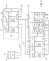
- an industrial automation system 5 includes a first (or primary) industrial automation controller 10 and a second (or secondary) industrial automation controller 15.
- the first and second industrial automation controllers 10 and 15 are modular and may be made up of numerous different modules connected together on a rack or rail (represented by dashed line 18). Additional modules may be added or existing modules removed and the first and second industrial automation controllers 10 and 15 reconfigured to accommodate the new configuration.
- both the first and second industrial automation controllers 10 and 15 include a power supply module 20, a controller module 25, and a network module 30.
- Each industrial automation controller 10 and 15 is further shown with an additional module 35 that may be selected according to the controller requirements.
- An example additional module is an analog or digital input or output module, which will be referred to herein generally as an I/O module.
- Another example additional module is a redundancy module for maintaining redundant information between the first industrial automation controller 10 and the second industrial automation controller 15.
- Other exemplary additional modules include an additional controller module or an additional network module.
- An operator interface 40 is shown connected to the industrial automation system 5.
- the operator interface 40 can include a processing portion 45, an input device 50, and an output device 55.
- the input device 50 can include, but not limited to, a keyboard, touchpad, mouse, trackball, or touch screen.
- the output device 55 can include, but not limited to, a display, speaker, or printer. It is contemplated that each component of the operator interface 40 may be incorporated into a single unit, such as an industrial computer, laptop, or tablet computer. It is further contemplated that multiple operator interfaces can be distributed about the industrial automation system 5.
- the operator interface 40 may be used to display operating parameters and/or conditions of the controlled machine or process, receive commands from the operator, or change and/or load a control program or configuration parameters.
- An interface cable 60 connects the operator interface 40 to the first industrial automation controller 10.
- the first and second industrial automation controllers 10 and 15 are connected to other devices by a network 62 according to the application requirements.
- An interface cable 65 connects the network modules 30 of the controllers 10 and 15.
- An interface cable 70 connects the first industrial controller to a first remote rack 85.
- An interface cable 75 connects the second industrial controller to a second remote rack 90.
- An interface cable 80 connects the first remote rack 85 to the second remote rack 90.
- the network cables 65-80 may be custom cables configured to communicate via a proprietary interface or may be a standard industrial cable for a non-proprietary network.
- Example non-proprietary networks include Ethernet/IP, DeviceNet, or ControlNet.
- the network cables 65-80 arrange the controllers and racks of the network 62 in what is referred to as a ring arrangement.
- the network modules 30 are configured to communicate according to the protocol of the network to which it is connected and may be further configured to translate messages between two different network protocols.
- each remote rack 85 and 90 is positioned at varying positions about the controlled automation system or process. As illustrated, each remote rack 85 and 90 is modular and may include numerous different modules connected together in a rack or mounted to a rail. Additional modules may be added or existing modules removed (e.g., one of the redundant network modules 30) and the remote rack 85 or 90 reconfigured to accommodate the new configuration.
- each remote rack 85 and 90 includes a pair of network modules 30.
- Each network module 30 is connected to one of the network cables 70-80, an input module 110, and an output module 115.
- Each pair of network modules 30 allows for network redundancy at the respective remote rack 85 or 90.
- Each of the input modules 110 is configured to receive input signals 120 from controlled devices 125.
- Each of the output modules 115 is configured to provide output signals 130 to the controlled devices 125.
- An input module and an output module may be combined into a singular module, and collectively the input and output modules may be referred to as I/O modules.
- still other modules 140 may be included in the remote rack 85. It is understood that the industrial automation system 5, the industrial automation controllers 10 and 15, and the remote racks 85 and 90 may take numerous other forms and configurations without deviating from the scope of the invention.
- each of the nodes in the network may include a processor 145 and a memory 150.
- the processors 145 are configured to execute instructions and to access or store operating data and/or configuration parameters stored in the corresponding memory 150.
- the processors 145 are suitable processors according to the node requirements. It is contemplated that the processors 145 may include a single processing device or multiple processing devices executing in parallel and may be implemented in separate electronic devices or incorporated on a single electronic device, such as a field programmable gate array (FPGA) or application specific integrated circuit (ASIC).
- FPGA field programmable gate array
- ASIC application specific integrated circuit
- the memory devices 150 are non-transitory storage mediums that may be a single device, multiple devices, or may be incorporated in part or in whole within the FPGA or ASIC.
- Each of the nodes also includes a clock circuit 155, and each clock circuit 155 is preferably synchronized with the other clock circuits 155 according to, for example, the IEEE-1588 clock synchronization standard.
- Each clock circuit 155 generates a time signal configurable to report the present time accurate to either microseconds or nanoseconds.
- Communication between nodes mounted in the same rack or contained within a single housing occurs via a backplane 160 and a corresponding backplane connector 165.
- Nodes communicating via network media 65-80 include ports 170 configured to process the corresponding network protocol.
- the input module 110 includes input terminals 175 configured to receive the input signals 120 ( FIG. 1 ) from the controlled devices 125, 135.
- the input module 110 also includes any associated logic circuitry 180 and internal connections 185 required to process and transfer the input signals 120 from the input terminals 175 to the processor 145.
- each output module 115 includes output terminals 190 configured to transmit the output signals 130 ( FIG. 1 ) to the controlled devices 125,135 ( FIG. 1 ).
- the output module 115 also includes any associated logic circuitry 195 and internal connections 200 required to process and transfer the output signals 130 from the processor 145 to the output terminals 190.
- FIG. 3 shows another exemplary automation system 205 including a first (or primary) industrial automation controller 210 and a second (or secondary) industrial automation controller 215.
- the first and second industrial automation controllers 210 and 215 are not shown in FIG. 3 as being multi-modular (as compared to the controllers 10 and 15 of FIG. 1 ), but are unitary industrial automation controllers with power supplies and communications built within the controllers.
- the first and second remote racks 220 and 225 are shown with the Input/Output (I/O) modules 230 as being unitary modules, unlike the distributed I/O modules 110 and 115 shown in FIG. 1 .
- I/O Input/Output
- FIG. 4 is a block diagram showing one example arrangement for the processor 145 and memory 150 of a controller module 25.
- the processor 145 includes multiple computer processing units.
- the first computer processing unit (CPU) 305 is a system CPU that executes application code and messages for communication with other components of the industrial automation system 5.
- the second CPU 310 is a backplane CPU that transfers I/O data and other module data on a backplane.
- the two CPUs 305 and 310 operate independently from each other.
- the memory is shown as having multiple memories.
- the memories include a project documentation memory 315, logic and data memory 320, and I/O memory 325.
- the project documentation memory 315 can include memory for comment descriptions, alarm logs, and data properties.
- the logic and data memory 315 includes memory for program source code, and program data.
- the I/O memory can include I/O data, message buffers, and similar data.
- the three memories can similarly operate independently of each other, i.e., the processors can access information from distinct memories at the same time. While one arrangement for a processor 145 and memory 150 is shown in FIG. 4 , it is contemplated that other arrangements and number of processors and/or memory can be different.
- Prior HA industrial automation systems include a data cross loading system having a high-speed data link for allowing rapid and bumpless transfer of control from the primary industrial automation controller to the secondary industrial automation controller when a malfunction occurs.
- bumpless systems have not been fully met without incurring various disadvantages as already discussed above.
- the industrial automation system 5 for example, does not utilize a dedicated high speed data link. The removal of the dedicated high speed link and related modules help to lower the cost of the improved industrial automation system 5.
- the industrial automation system 5 also utilizes lower levels of synchronization by allowing the user to configure the industrial automation system 5. Configuring the industrial automation system 5 allows for trading features with performance.
- the user can provide configuration input via the operator interface 40.
- the user may identify to the industrial automation controller 10 that it is the primary controller and that the industrial automation controller 15 is the secondary (or backup) controller.
- the user may also identify other components coupled to the industrial automations system 5 to the primary industrial automation controller 10. Further configuring and programming of the industrial automation system 5 can be done as is customary to one skilled in the art.
- the primary industrial automation controller 10 controls the first and second remote racks 85 and 90 and cross loads information to the secondary industrial automation controller 15.
- the controlling of the industrial automation system 5 and cross loading of information is accomplished over network 62.
- More related to embodiments of the invention is the further configuring of the primary industrial automation controller 10, via the operator interface 40, to cross load less than full synchronization information between the primary industrial automation controller 10 and the secondary industrial automation controller 15.
- the user can enter a command to the primary industrial automation controller 10 to (a) cross load program synchronization information and input/output (I/O) synchronization information, (b) cross load program synchronization information and not I/O synchronization information, (c) cross load I/O synchronization information and not program synchronization information, and (d) cross load neither I/O synchronization information nor program synchronization information.
- I/O input/output
- An example of program synchronization information includes industrial automation tasks (e.g., event tasks, periodic tasks, continuous tasks) to be used by the first remote rack 85 and/or the second remote rack 90.
- An example of I/O synchronization information includes I/O data acquired from the devices 125 during operation of one or more industrial automation tasks.
- the improved industrial automation system 5 allows for trading features with performance.
- option (a) above, the industrial automation system 5 still allows for full synchronization, but the synchronization may be delayed by data congestion on the network 62. This may create a "bump" in the industrial automation system 5 when the secondary industrial automation controller 15 takes over from the primary industrial automation controller 10 since the cross loading of information may not be fully synchronized. Presumably the bump will be acceptable otherwise a user may select a different industrial automation system with a dedicated synchronization connection. Also this option is selected for the expectation that the network 62 has little data congestion among the various components to allow for the full synchronization to occur.
- options (b) or (c), above When data congestion is higher than what is acceptable for option (a), the user may select options (b) or (c), above. Options (b) and (c) still allow for some synchronization among the industrial automation controllers 10 and 15 to improve performance over a non-synchronized system; but the reduced synchronization improves data congestion on the network 62 since less than full synchronization occurs.
- a bump in the industrial automation system 5 occurs when the secondary industrial automation controller 15 takes over from the primary industrial automation controller 10.
- the bump occurs since the default I/O synchronization information is not as current as the I/O synchronization information of the primary industrial automation controller 10. However, the user has deemed the bump to be acceptable.
- the secondary industrial automation controller 15 may include a program, such as a shutdown program, that is acceptable to the user when the secondary industrial automation controller 15 takes over from the primary industrial automation controller 10.
- a program such as a shutdown program
- the cross loading of I/O synchronization information is deemed by the user as necessary in option (c) to allow the secondary industrial automation controller to function.
- the user may configure the primary industrial automation controller with option (d), above. It is not envisioned that this feature will be selected often since no cross loading will take place between the industrial automation controllers 10 and 15. However, it is conceivable that the network 62 may-become too congested such that no cross loading may be desired.
- embodiments of the invention can also allow for a similar look and feel to the full implementation of the system described in U.S. Patent No. 5,777,874 , but with reduced functionality. This will allow a manufacturer to provide a family of customizable products to the consumer.
- the control program loaded into each of the primary controller 10 and the secondary controller 15 includes a verification tag associated with the program.
- the verification tag may be generated by programming software when the control program is created prior to loading the program into the controller.
- the verification tag may be generated by the primary controller when a new control program is loaded into the controller. It is further contemplated that the verification tag may be modified if, for example, a technician modifies the control program, or a portion thereof, within the controller after it has already been downloaded.
- the verification tag maybe generated by any suitable method. It is contemplated that the verification tag may be, for example, a single number or a data string, such as a checksum, generated as a function of the content of the control program; a user defined name assigned to the control program, where the name must be unique for each program; a value generated based on the time the control program is created; an incremental value that is automatically updated by the programming software each time the control program is changed; or any combination thereof.
- the verification tag is stored in the memory of the primary controller 10.
- the user may configure whether the program is synchronized between the primary and secondary controllers 10, 15 as an option of the HA system.
- the primary controller 10 transfers the verification tag associated with the control program along with the control program to the secondary controller 15. If program synchronization is not selected, a separate verification tag is loaded into each controller when the corresponding control program is loaded into the controller. Similarly, should the control program be modified on either the primary or secondary controller 10, 15, the verification tag changes on the controller to which modifications are made.
- the verification tag for each controller 10, 15 is transmitted to the other controller even if the program synchronization is not selected. Because the verification tag is a single number or string of data, it does not require significant bandwidth for transmission.
- the HA system typically needs to continue operation under various fault conditions.
- One such fault condition is the failure of a controller. If the controller presently controlling operation of the industrial automation system 5 (i.e., either the primary controller 10 or the secondary controller 15) enters a fault state such that the controller no longer can continue operating, the HA system may execute a switchover such that the other controller continues operation of the system. Because it is possible that the two control programs are not identical (i..e., program synchronization was not selected) the controller is configured to compare the verification tag for the control program presently loaded in the controller that is to begin operating to the verification tag of the controller previously operating. If the two verification tags are identical, the switchover is allowed to proceed and the secondary controller continues operation of the HA system.
- the new controller may immediately shut down due to the differences in the program.
- the new controller may enter a controlled shut down state, to allow the controlled system to continue operating for a period of time.
- the new controller may be allowed to take over operation of the controlled process with the different control program but simply post a message alerting the operator of the condition such that the operator may take action according to the application requirements.
Landscapes
- Engineering & Computer Science (AREA)
- Physics & Mathematics (AREA)
- General Physics & Mathematics (AREA)
- General Engineering & Computer Science (AREA)
- Automation & Control Theory (AREA)
- Theoretical Computer Science (AREA)
- Manufacturing & Machinery (AREA)
- Quality & Reliability (AREA)
- Software Systems (AREA)
- Programmable Controllers (AREA)
Claims (5)
- Procédé de communication d'informations d'un premier contrôleur d'automatisation industrielle (10 ; 210) à un deuxième contrôleur d'automatisation industrielle (15 ; 215) d'un réseau à haute disponibilité, le procédé caractérisé en ce qu'il comprend les étapes de :réception d'une commande entrée par un utilisateur pour effectuer un chargement croisé de tâches d'automatisation industrielle à utiliser par un châssis distant (85, 95) et sans chargement croisé de données d'entrée/sortie, I/O (Input/Output), acquises auprès de dispositifs contrôlés (125) au cours d'une exécution des tâches d'automatisation industrielle entre le premier contrôleur d'automatisation industrielle et le deuxième contrôleur d'automatisation industrielle ;aucun chargement croisé des données I/O entre le premier contrôleur d'automatisation industrielle et le deuxième contrôleur d'automatisation industrielle selon la commande reçue ; etchargement croisé des tâches d'automatisation industrielle du premier contrôleur d'automatisation industrielle vers le deuxième contrôleur d'automatisation industrielle.
- Contrôleur d'automatisation industrielle principal (10 ; 210) raccordable à un contrôleur d'automatisation industrielle secondaire (15 ; 215) via un réseau de communication, le contrôleur d'automatisation industrielle principal comprenant :un module de processeur monté sur un châssis doté d'une carte de fond de panier (160) pour faciliter une communication au niveau du contrôleur d'automatisation industrielle, le module de processeur incluant un processeur (145) et un support de stockage non transitoire (150), le processeur et le support de stockage non transitoire configuré pour stocker une pluralité d'instructions, une pluralité de tâches d'automatisation à utiliser par un châssis distant (85, 95), et des données d'entrée/sortie, I/O (Input/Output), acquises auprès de dispositifs contrôlés (125) au cours d'une exécution des tâches d'automatisation, le contrôleur d'automatisation industrielle principal (10 ; 210) étant caractérisé en ce que le processeur est adapté pour exécuter la pluralité d'instructions pour recevoir une commande entrée par un utilisateur pour effectuer un chargement croisé de la pluralité de tâches d'automatisation et sans chargement croisé des données d'entrée/sortie, I/O (Input/Output), entre le contrôleur d'automatisation industrielle principal et le contrôleur d'automatisation industrielle secondaire,ne pas effectuer de chargement croisé des données I/O entre le contrôleur d'automatisation industrielle principal et le contrôleur d'automatisation industrielle secondaire selon la commande reçue, eteffectuer un chargement croisé de la pluralité de tâches d'automatisation industrielle du contrôleur d'automatisation industrielle principal vers le contrôleur d'automatisation industrielle secondaire ; etle contrôleur d'automatisation industrielle principal (10 ; 210) comprenant en outre un premier module de communication monté sur le châssis doté d'une carte de fond de panier (160), couplé au module de processeur et raccordable au réseau.
- Système d'automatisation industrielle à haute disponibilité (5), le système comprenant :le contrôleur d'automatisation industrielle principal de la revendication 2 ;le contrôleur d'automatisation industrielle secondaire incluant un deuxième processeur et un deuxième support de stockage non transitoire configuré pour stocker une deuxième pluralité d'instructions, une deuxième pluralité de tâches d'automatisation et des deuxièmes données E/S ; etle réseau de communication connecté au contrôleur d'automatisation industrielle principal et au contrôleur d'automatisation industrielle secondaire.
- Le système d'automatisation industrielle à haute disponibilité de la revendication 3, dans lequel le contrôleur d'automatisation industrielle secondaire inclut en outre un deuxième module de processeur et un deuxième module de communication montés sur un deuxième châssis doté d'une deuxième carte de fond de panier pour faciliter une communication au niveau du contrôleur d'automatisation industrielle secondaire, le deuxième module de processeur incluant le deuxième processeur et le deuxième support de stockage non transitoire, et
dans lequel le réseau de communication est en outre connecté au contrôleur d'automatisation industrielle principal et au contrôleur d'automatisation industrielle secondaire via le premier module de communication et le deuxième module de communication, respectivement. - Le système d'automatisation industrielle à haute disponibilité de l'une des revendications 3 à 4, comprenant en outre le châssis distant pour contrôler un dispositif d'entrée et un dispositif de sortie, le châssis distant incluant un troisième module de communication monté sur un troisième châssis doté d'une troisième carte de fond de panier pour faciliter une communication au niveau du châssis distant,dans lequel le réseau de communication est connecté en outre au châssis distant via le troisième module de communication, etdans lequel le chargement croisé d'informations du contrôleur d'automatisation industrielle principal vers le contrôleur d'automatisation industrielle secondaire est effectué sur le réseau de communication.
Applications Claiming Priority (1)
| Application Number | Priority Date | Filing Date | Title |
|---|---|---|---|
| US16/145,697 US11022962B2 (en) | 2018-09-28 | 2018-09-28 | High availability industrial automation system having primary and secondary industrial automation controllers and method of communicating information over the same |
Publications (2)
| Publication Number | Publication Date |
|---|---|
| EP3629114A1 EP3629114A1 (fr) | 2020-04-01 |
| EP3629114B1 true EP3629114B1 (fr) | 2024-06-05 |
Family
ID=68066593
Family Applications (1)
| Application Number | Title | Priority Date | Filing Date |
|---|---|---|---|
| EP19199157.9A Active EP3629114B1 (fr) | 2018-09-28 | 2019-09-24 | Système d'automatisation industrielle haute disponibilité doté d'organes de commande d'automatisation industrielle primaire et secondaire et procédé de communication d'informations par celui-ci |
Country Status (3)
| Country | Link |
|---|---|
| US (1) | US11022962B2 (fr) |
| EP (1) | EP3629114B1 (fr) |
| CN (1) | CN110967969B (fr) |
Families Citing this family (7)
| Publication number | Priority date | Publication date | Assignee | Title |
|---|---|---|---|---|
| US11481282B2 (en) * | 2019-03-29 | 2022-10-25 | Honeywell International Inc. | Redundant controllers or input-output gateways without dedicated hardware |
| US10838386B1 (en) * | 2019-09-26 | 2020-11-17 | Rockwell Automation Technologies, Inc. | Distributed modular I/O device with configurable single-channel I/O submodules |
| US11762742B2 (en) | 2020-03-31 | 2023-09-19 | Honeywell International Inc. | Process control system with different hardware architecture controller backup |
| US11989084B2 (en) | 2020-09-23 | 2024-05-21 | Honeywell International Inc. | Self-healing process control system |
| US11768479B2 (en) | 2020-09-30 | 2023-09-26 | Rockwell Automation Technologies, Inc. | System and method for secure connections in a high availability industrial controller |
| US11874938B2 (en) | 2020-11-03 | 2024-01-16 | Honeywell International Inc. | Admittance mechanism |
| CN113495484A (zh) * | 2021-06-21 | 2021-10-12 | 宝信软件(武汉)有限公司 | 一种工业水处理循环控制的多切换系统 |
Citations (1)
| Publication number | Priority date | Publication date | Assignee | Title |
|---|---|---|---|---|
| EP1517203B1 (fr) * | 2003-09-16 | 2012-11-07 | Rockwell Automation Technologies, Inc. | Commande de sécurité avec une interface simplifiée |
Family Cites Families (8)
| Publication number | Priority date | Publication date | Assignee | Title |
|---|---|---|---|---|
| US5777874A (en) | 1996-02-12 | 1998-07-07 | Allen-Bradley Company, Inc. | Programmable controller backup system |
| US5966304A (en) * | 1997-04-29 | 1999-10-12 | Allen-Bradley Company, Llc | Redundant automation controller permitting replacement of components during operation |
| US5933347A (en) * | 1997-06-13 | 1999-08-03 | Allen-Bradley Company Llc | Industrial controller with program synchronized updating of back-up controller |
| US5997166A (en) * | 1997-06-18 | 1999-12-07 | Allen-Bradley Company, Llc | Redundant industrial controller storing module and chassis level redundancy status |
| US8359112B2 (en) * | 2006-01-13 | 2013-01-22 | Emerson Process Management Power & Water Solutions, Inc. | Method for redundant controller synchronization for bump-less failover during normal and program mismatch conditions |
| US8364291B2 (en) | 2007-11-13 | 2013-01-29 | Rockwell Automation Technologies, Inc. | Method and apparatus for providing redundancy in an industrial control system |
| US8046444B2 (en) * | 2009-03-30 | 2011-10-25 | Rockwell Automation Technologies, Inc. | Universal network adapter for industrial control networks |
| US9703277B2 (en) * | 2014-05-07 | 2017-07-11 | Rockwell Automation Technologies, Inc. | Method and apparatus to track changes in an industrial controller |
-
2018
- 2018-09-28 US US16/145,697 patent/US11022962B2/en active Active
-
2019
- 2019-09-24 EP EP19199157.9A patent/EP3629114B1/fr active Active
- 2019-09-26 CN CN201910917471.1A patent/CN110967969B/zh active Active
Patent Citations (1)
| Publication number | Priority date | Publication date | Assignee | Title |
|---|---|---|---|---|
| EP1517203B1 (fr) * | 2003-09-16 | 2012-11-07 | Rockwell Automation Technologies, Inc. | Commande de sécurité avec une interface simplifiée |
Also Published As
| Publication number | Publication date |
|---|---|
| US11022962B2 (en) | 2021-06-01 |
| US20200103861A1 (en) | 2020-04-02 |
| CN110967969A (zh) | 2020-04-07 |
| CN110967969B (zh) | 2023-06-16 |
| EP3629114A1 (fr) | 2020-04-01 |
Similar Documents
| Publication | Publication Date | Title |
|---|---|---|
| EP3629114B1 (fr) | Système d'automatisation industrielle haute disponibilité doté d'organes de commande d'automatisation industrielle primaire et secondaire et procédé de communication d'informations par celui-ci | |
| RU2750580C2 (ru) | Способы и устройство для осуществления связи через удаленное терминальное устройство | |
| US8132042B2 (en) | Method and device for exchanging data on the basis of the OPC communications protocol between redundant process automation components | |
| US7774073B2 (en) | Modular programmable automation controller with multi-processor architecture | |
| EP3629110B1 (fr) | Dispositif de commande d'automatisation industrielle haute disponibilité et son procédé de fonctionnement | |
| US11221612B2 (en) | System and method of communicating data over high availability industrial control systems | |
| CN110799912B (zh) | 安全关键和非安全关键的过程的控制系统 | |
| EP1949248A1 (fr) | Systeme avionique modulaire d'un avion | |
| EP1334412A2 (fr) | Procede et appareil permettant d'assurer un systeme de commande auxiliaire actif sur un reseau | |
| EP3026556B1 (fr) | Gestion de génération d'événement pour un contrôleur industriel | |
| US7023795B1 (en) | Method and apparatus for an active standby control system on a network | |
| RU2510932C2 (ru) | Система автоматизации и способ управления системой автоматизации | |
| US20180373213A1 (en) | Fieldbus coupler and system method for configuring a failsafe module | |
| US11740604B2 (en) | Control device | |
| KR20110123168A (ko) | Hmi 이중화 장치 | |
| JP4408259B2 (ja) | 動作制御システム | |
| EP2413208B1 (fr) | Connectivité entre processeurs | |
| KR100724495B1 (ko) | 피엘씨 이중화 시스템 및 운전 방법 | |
| US7185129B2 (en) | Method for configuring and/or operating an automation device having a master unit connected to one or more slave units | |
| KR100729930B1 (ko) | 이중화 시스템의 절체 회로 | |
| JP7349416B2 (ja) | 分散制御システム | |
| KR101122796B1 (ko) | Plc 시스템 | |
| JP7326239B2 (ja) | コントローラ、および、コントローラシステム |
Legal Events
| Date | Code | Title | Description |
|---|---|---|---|
| PUAI | Public reference made under article 153(3) epc to a published international application that has entered the european phase |
Free format text: ORIGINAL CODE: 0009012 |
|
| STAA | Information on the status of an ep patent application or granted ep patent |
Free format text: STATUS: THE APPLICATION HAS BEEN PUBLISHED |
|
| AK | Designated contracting states |
Kind code of ref document: A1 Designated state(s): AL AT BE BG CH CY CZ DE DK EE ES FI FR GB GR HR HU IE IS IT LI LT LU LV MC MK MT NL NO PL PT RO RS SE SI SK SM TR |
|
| AX | Request for extension of the european patent |
Extension state: BA ME |
|
| STAA | Information on the status of an ep patent application or granted ep patent |
Free format text: STATUS: REQUEST FOR EXAMINATION WAS MADE |
|
| 17P | Request for examination filed |
Effective date: 20200917 |
|
| RBV | Designated contracting states (corrected) |
Designated state(s): AL AT BE BG CH CY CZ DE DK EE ES FI FR GB GR HR HU IE IS IT LI LT LU LV MC MK MT NL NO PL PT RO RS SE SI SK SM TR |
|
| STAA | Information on the status of an ep patent application or granted ep patent |
Free format text: STATUS: EXAMINATION IS IN PROGRESS |
|
| 17Q | First examination report despatched |
Effective date: 20210716 |
|
| GRAP | Despatch of communication of intention to grant a patent |
Free format text: ORIGINAL CODE: EPIDOSNIGR1 |
|
| STAA | Information on the status of an ep patent application or granted ep patent |
Free format text: STATUS: GRANT OF PATENT IS INTENDED |
|
| INTG | Intention to grant announced |
Effective date: 20240111 |
|
| GRAS | Grant fee paid |
Free format text: ORIGINAL CODE: EPIDOSNIGR3 |
|
| GRAA | (expected) grant |
Free format text: ORIGINAL CODE: 0009210 |
|
| STAA | Information on the status of an ep patent application or granted ep patent |
Free format text: STATUS: THE PATENT HAS BEEN GRANTED |
|
| AK | Designated contracting states |
Kind code of ref document: B1 Designated state(s): AL AT BE BG CH CY CZ DE DK EE ES FI FR GB GR HR HU IE IS IT LI LT LU LV MC MK MT NL NO PL PT RO RS SE SI SK SM TR |
|
| REG | Reference to a national code |
Ref country code: CH Ref legal event code: EP |
|
| REG | Reference to a national code |
Ref country code: DE Ref legal event code: R096 Ref document number: 602019053176 Country of ref document: DE |
|
| REG | Reference to a national code |
Ref country code: IE Ref legal event code: FG4D |