EP3628611B1 - Cellular wheel lock for granular bulk material - Google Patents
Cellular wheel lock for granular bulk material Download PDFInfo
- Publication number
- EP3628611B1 EP3628611B1 EP19194524.5A EP19194524A EP3628611B1 EP 3628611 B1 EP3628611 B1 EP 3628611B1 EP 19194524 A EP19194524 A EP 19194524A EP 3628611 B1 EP3628611 B1 EP 3628611B1
- Authority
- EP
- European Patent Office
- Prior art keywords
- granulate
- cellular wheel
- groove
- roofs
- housing
- Prior art date
- Legal status (The legal status is an assumption and is not a legal conclusion. Google has not performed a legal analysis and makes no representation as to the accuracy of the status listed.)
- Active
Links
- 230000001413 cellular effect Effects 0.000 title claims description 49
- 239000013590 bulk material Substances 0.000 title description 19
- 239000008187 granular material Substances 0.000 claims description 136
- 230000007704 transition Effects 0.000 claims description 9
- 238000006073 displacement reaction Methods 0.000 claims 3
- 238000005266 casting Methods 0.000 description 4
- 230000006378 damage Effects 0.000 description 4
- 238000004519 manufacturing process Methods 0.000 description 3
- 238000005520 cutting process Methods 0.000 description 2
- FGRBYDKOBBBPOI-UHFFFAOYSA-N 10,10-dioxo-2-[4-(N-phenylanilino)phenyl]thioxanthen-9-one Chemical compound O=C1c2ccccc2S(=O)(=O)c2ccc(cc12)-c1ccc(cc1)N(c1ccccc1)c1ccccc1 FGRBYDKOBBBPOI-UHFFFAOYSA-N 0.000 description 1
- TVEXGJYMHHTVKP-UHFFFAOYSA-N 6-oxabicyclo[3.2.1]oct-3-en-7-one Chemical compound C1C2C(=O)OC1C=CC2 TVEXGJYMHHTVKP-UHFFFAOYSA-N 0.000 description 1
- 229920000426 Microplastic Polymers 0.000 description 1
- 230000000694 effects Effects 0.000 description 1
- 230000005484 gravity Effects 0.000 description 1
- 238000009434 installation Methods 0.000 description 1
- 239000002245 particle Substances 0.000 description 1
- 230000002093 peripheral effect Effects 0.000 description 1
- 230000000750 progressive effect Effects 0.000 description 1
Images


Classifications
-
- B—PERFORMING OPERATIONS; TRANSPORTING
- B65—CONVEYING; PACKING; STORING; HANDLING THIN OR FILAMENTARY MATERIAL
- B65G—TRANSPORT OR STORAGE DEVICES, e.g. CONVEYORS FOR LOADING OR TIPPING, SHOP CONVEYOR SYSTEMS OR PNEUMATIC TUBE CONVEYORS
- B65G53/00—Conveying materials in bulk through troughs, pipes or tubes by floating the materials or by flow of gas, liquid or foam
- B65G53/34—Details
- B65G53/40—Feeding or discharging devices
- B65G53/46—Gates or sluices, e.g. rotary wheels
- B65G53/4608—Turnable elements, e.g. rotary wheels with pockets or passages for material
- B65G53/4625—Turnable elements, e.g. rotary wheels with pockets or passages for material with axis of turning perpendicular to flow
- B65G53/4633—Turnable elements, e.g. rotary wheels with pockets or passages for material with axis of turning perpendicular to flow the element having pockets, rotated from charging position to discharging position, i.e. discrete flow
-
- B—PERFORMING OPERATIONS; TRANSPORTING
- B65—CONVEYING; PACKING; STORING; HANDLING THIN OR FILAMENTARY MATERIAL
- B65G—TRANSPORT OR STORAGE DEVICES, e.g. CONVEYORS FOR LOADING OR TIPPING, SHOP CONVEYOR SYSTEMS OR PNEUMATIC TUBE CONVEYORS
- B65G53/00—Conveying materials in bulk through troughs, pipes or tubes by floating the materials or by flow of gas, liquid or foam
- B65G53/34—Details
- B65G53/40—Feeding or discharging devices
- B65G53/46—Gates or sluices, e.g. rotary wheels
-
- B—PERFORMING OPERATIONS; TRANSPORTING
- B65—CONVEYING; PACKING; STORING; HANDLING THIN OR FILAMENTARY MATERIAL
- B65G—TRANSPORT OR STORAGE DEVICES, e.g. CONVEYORS FOR LOADING OR TIPPING, SHOP CONVEYOR SYSTEMS OR PNEUMATIC TUBE CONVEYORS
- B65G65/00—Loading or unloading
- B65G65/30—Methods or devices for filling or emptying bunkers, hoppers, tanks, or like containers, of interest apart from their use in particular chemical or physical processes or their application in particular machines, e.g. not covered by a single other subclass
- B65G65/34—Emptying devices
- B65G65/40—Devices for emptying otherwise than from the top
- B65G65/48—Devices for emptying otherwise than from the top using other rotating means, e.g. rotating pressure sluices in pneumatic systems
- B65G65/4881—Devices for emptying otherwise than from the top using other rotating means, e.g. rotating pressure sluices in pneumatic systems rotating about a substantially horizontal axis
-
- B—PERFORMING OPERATIONS; TRANSPORTING
- B65—CONVEYING; PACKING; STORING; HANDLING THIN OR FILAMENTARY MATERIAL
- B65G—TRANSPORT OR STORAGE DEVICES, e.g. CONVEYORS FOR LOADING OR TIPPING, SHOP CONVEYOR SYSTEMS OR PNEUMATIC TUBE CONVEYORS
- B65G2201/00—Indexing codes relating to handling devices, e.g. conveyors, characterised by the type of product or load being conveyed or handled
- B65G2201/04—Bulk
- B65G2201/042—Granular material
-
- B—PERFORMING OPERATIONS; TRANSPORTING
- B65—CONVEYING; PACKING; STORING; HANDLING THIN OR FILAMENTARY MATERIAL
- B65G—TRANSPORT OR STORAGE DEVICES, e.g. CONVEYORS FOR LOADING OR TIPPING, SHOP CONVEYOR SYSTEMS OR PNEUMATIC TUBE CONVEYORS
- B65G2207/00—Indexing codes relating to constructional details, configuration and additional features of a handling device, e.g. Conveyors
- B65G2207/40—Safety features of loads, equipment or persons
Definitions
- the invention relates to a star feeder for granular bulk material.
- the JP S62-059622 U discloses a cellular wheel sluice, at the inlet shaft of which a granulate roof is arranged on the housing, with a granulate groove being provided at the transition between a granulate roof and the inlet shaft.
- Similar rotary valves are known from DE 42 28 014 C1 , U.S. 2013/146797 A1 and CN 106 429 249 A .
- the granulate groove reduces the risk of a granulate of the bulk material falling into the already largely filled chamber of the star feeder and being sheared off and/or cut off between the edge of the housing and the rotor blade.
- chopping, ie destruction, of the granulate can nevertheless occur.
- the end of the groove is called the intersection point.
- DE 28 06 059 A1 US 4,537,333A and GB 1 385 332 A each disclose cellular wheel sluices with multiple granular roofs. Specifically revealed DE 28 06 059 A1 a rotary valve according to the preamble of claim 1.
- this object is achieved by a cellular wheel sluice having the features specified in claim 1 .
- the inflow behavior for bulk material in a cellular wheel sluice can be improved if a surface on the inflow shaft is enlarged.
- at least two raised granulate roofs are arranged on the inlet shaft.
- the respective granulate roof is designed in particular in the form of a nose.
- the granulate roof In a viewing direction from above into the inlet shaft, the granulate roof is designed in the shape of a triangle.
- the granulate roof improves the infeed behavior of granular bulk material.
- two granulate grooves each arranged at the transition between two granulate roofs and at the transition between a granulate roof and an inlet edge are each brought together at an intersection point.
- Inlet edges are edges on the inlet shaft through which the granules are fed from the inlet shaft into the cylinder bore of the rotary valve housing.
- the inlet edge is arranged in particular at the transition to the inlet shaft.
- the granular bulk material can enter the cell wheel chamber via the inlet edge.
- the ratio of the surface area at the inlet shaft to the number of intersection points is increased, in particular disproportionately.
- a rotary valve with three granulate roofs has only two intersection points.
- the conveying capacity is increased and the cutting behavior or chopping behavior is reduced.
- a key finding is based on the fact that a surface of a large granulate roof is divided into several comparatively smaller granulate roofs can be. For example, two granule roofs, three granule roofs, four granule roofs or five granule roofs or more can be provided.
- the roofs of granules are arranged side by side along a width of the manhole.
- the width of the inlet shaft is oriented parallel to the axis of rotation of the star feeder.
- the enlarged surface at the inlet shaft between 110% and 150% of the surface of a rotary valve of the same type with only one granulate roof, in particular between 120% and 140% and in particular between 125% and 135%.
- the lock according to the invention can be filled reliably and failsafe even at high speeds, in particular rotor peripheral speeds of at least 1 m/s and in particular of at least 2 m/s.
- the degree of filling of the individual chambers of the star feeder is improved.
- the mass throughput of the rotary valve is increased.
- the housing of the cellular wheel sluice has a cylinder bore, which is also referred to as the interior of the cellular wheel sluice.
- a cellular wheel sluice according to claim 2 enables a constant deflection behavior of the cellular wheel. It was found that the deflection angle is a relevant parameter for the deflection behavior of the granulate grain in the granulate groove, which depends in particular on the rotary position of the cellular wheel in the housing of the cellular wheel sluice. It was found that the constant deflection behavior is achieved when the deflection angle is constant at least in sections.
- the deflection angle is at least 50% of the total length of the granulate groove, in particular over 60% of the total length of the granulate groove, in particular over 70% of the total length of the granulate groove, in particular over 80% of the total length of the granulate groove, in particular over 90% of the total length of the granulate groove, in particular constant over 95% of the total length of the granulate groove and in particular along the total length of the granulate groove.
- the deflection angle can increase at least in sections in the direction of rotation of the cellular wheel.
- the increase can be linear or progressive, for example.
- the increase can also be continuous along the entire length of the granulate groove.
- the deflection angle can be at least 35° at the beginning of the granulate groove and at most 70° at the end of the granulate groove, in particular at the point of intersection.
- Such a granule groove may appear as if the deflection angle is constant in a projection in the horizontal plane due to the curved surface on the inside of the cylinder bore. In fact, the deflection angle increases in sections in the direction of rotation of the star feeder.
- a cellular wheel sluice according to claim 4 has an improved conveying behavior. Chopping of the granules is essentially prevented.
- a granulate groove according to claim 5 allows an advantageous - pushing the bulk material along the granulate groove.
- the cross-sectional area of the granulate groove can essentially be selected as desired.
- the cross-sectional area can be square, rectangular or triangular, in particular with a rounded tip. Other, in particular rounded, cross-sectional shapes are also conceivable for the granulate groove.
- the design of a granulate groove according to claim 6 improves the deflection behavior for the granulate grain in the star feeder. It was found that a sharp-edged design of the granulate groove should be avoided as seen from the interior of the rotary valve.
- a granulate groove according to claim 7 enables an advantageous production of the housing.
- a core part can be saved when casting the housing.
- the risk of damage to the granulate grain is additionally reduced.
- the integral length of all the granule grooves is increased so that the granule grains can be prevented from sliding along the granule groove up to the point of intersection.
- an embodiment of a cellular wheel sluice according to claim 9 enables an increased conveying capacity.
- the inlet area of the rotary valve is comparatively large and enables an increased mass flow of bulk material into the rotary valve through the inlet shaft.
- a cellular wheel sluice according to claim 10 enables an improved push-off effect on the granular bulk material falling into the inlet shaft.
- the probability that a granule grain can get between the tip of the nose, i.e. the front end of the granulate roof, and the cellular wheel ridge is reduced.
- the risk of the bulk material being chipped at this point is reduced.
- Figures 1 to 8 shown designated as a whole with 1 rotary valve is used for the metered promotion of granular bulk material, especially plastic granules.
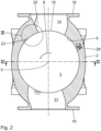
- the cellular wheel sluice 1 comprises a housing 2 with a cylindrical bore 3 in which a cellular wheel 4 is arranged coaxially so as to be rotatably driven about an axis of rotation 5 .
- the cylinder bore 3 forms the interior of the housing 2.
- the star feeder 4 has a star feeder shaft 6 and a plurality of star feeders 7 attached to the star feeder shaft 6 in a radially oriented manner with respect to the axis of rotation 5 .
- the cellular wheel webs 7 are arranged in the direction of rotation 8 around the axis of rotation 5 at equal distances from one another.
- a star feeder chamber 10 is delimited, into which the granular bulk material is dosed for promotion.
- the star feeder 4 has twelve star feeders 7, so that twelve star feeder chambers 10 are formed.
- the number of star feeders 7 can be selected to be larger or smaller depending on the intended use of the star feeder 4 in order to set a finer or coarser division of the star feeder chambers 10 accordingly.
- the housing 2 can be closed and sealed at the end along the axis of rotation 5 with a side cover, not shown. That points to that Housing 2 each have a frontally arranged, on the housing 2 running integrated connecting flange 12. A plurality of fastening bores (not shown) are provided on the connecting or side flange 12 in order to attach the housing cover to the side flange 12 in a detachable and sealed manner by means of fastening screws.
- a seal in particular an O-ring or a flat seal, can be arranged between the side flange 12 and the side cover.
- the leakage air duct 28 can have two lines running parallel to one another in some areas, which in 4 are shown.
- the leakage air duct 28 can additionally or alternatively have built-in components for noise reduction, which are not shown.
- the housing 2 has an inlet shaft 14, via which the bulk material is fed to the cellular wheel sluice 1, in particular the cylinder bore 3, with the cellular wheel 4.
- the inlet shaft 14 In an installation position of the rotary valve 1, as in 2 and 7 shown, the inlet shaft 14 is arranged at the top, so that the supplied bulk material is automatically conveyed into the cylinder bore 3 due to the force of gravity.
- the inlet shaft 14 has an inlet slope 15 along which the granular bulk material flows into the cylinder bore 3 .
- the inlet shaft 14 is connected to the cylinder bore 3 via an inlet opening 16 .
- the inlet opening 16 has a width B oriented parallel to the axis of rotation 5 . According to a projection of the inlet opening 16 in a horizontal plane 1 the inlet opening 16 has a length L oriented perpendicularly to the width B.
- the inlet shaft 14 has a connecting flange 18 which is designed to correspond to the connecting flanges 12 arranged on the face side. According to the exemplary embodiment shown, sixteen fastening bores 13 are provided on the connecting flange 18 of the inlet shaft 14 .
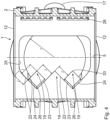
- each nose-shaped granulate roofs 19 is arranged at the inlet shaft 14, in particular along the inlet slope 15, three nose-shaped granulate roofs 19 are arranged.
- the granulate roofs 19 are raised relative to the inlet slope 15 .
- the granulate roofs 19 increase the surface area of the inlet slope 15 in the inlet shaft 14.
- the granulate roofs 19 are arranged on the inlet slope 15 in the manner of an equilateral gable roof.
- the granulate roofs 19 extend from the inlet slope 15 like a dormer.
- Each granulate roof 19 has a ridge 20 and two elongated surfaces 21 each arranged inclined at an angle of inclination ⁇ with respect to a vertical plane, which is oriented in particular perpendicularly to the axis of rotation 5 .
- the free edges of the long surfaces 21, which are arranged facing away from the inlet slope 15, are referred to as deflection edges 22.
- the deflecting edge 22 is also referred to as the entry
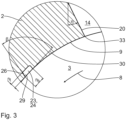
- the granulate roofs 19 extend at the inlet slope 15 in the inlet shaft 14 up to the star feeder hole 3, as is shown in particular in 2 and in detail in 3 is shown.
- the granulate roofs 19 each have the ridge 20 as the front edge, which ends at a lower, front tip 33 .
- the tip 33 faces the cylinder bore 3 and represents the transition between the inlet slope 15 with the granulate roof 19 and the cylinder bore 3
- the granulate roofs 19 are arranged next to one another along the width direction, ie in a direction parallel to the axis of rotation 5 .
- the granulate roofs 19 are arranged on the inlet slope 15 in such a way that the respective ridge 20 is oriented transversely and in particular perpendicularly to the axis of rotation 5 .
- a first granulate groove 23 is formed in each transition region between two adjacent granulate roofs 19 .
- the first granulate groove 23 is arranged in particular as a groove-like depression on a virtual abutting edge of the respective long faces 21 of the adjacent granulate roofs 19 .
- a second granulate groove 24, which is essentially identical to the first granulate groove 23, is arranged on an outer side of the outer granulate roof 19, i.e. in a transition area between the respective outer granulate roof 19 and an inner boundary wall of the inlet shaft 14.
- the boundary wall has an upper boundary edge 25 facing the inlet shaft 14 .
- the boundary edge 25 forms an inlet edge.
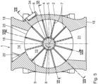
- the granulate grooves 23, 24 are each designed as a groove-shaped depression on the lateral surface 9 of the cylinder bore 3.
- the granulate grooves 23, 24 extend in the direction of rotation 8 of the bucket wheel 4.
- Two granulate grooves 23, 24 each converge at an intersection point 26.
- the point of intersection 26 is not to be understood as a point in the geometric sense. This is the connection point between two grooves, in particular a connection area, for example a cutting plane and/or an edge, as in particular in 4 shown.
- the number of intersection points namely two, is in particular based on the total number of granulate roofs 19, namely three, reduced.
- the cellular wheel sluice 1 optimizes the number of granulate roofs 19 to that of the intersection points 26.
- the surface area in the area of the inlet shaft is increased by the granulate roofs 19 by at least 20%, in particular at least 25% and in particular at least 30% compared to a comparable star feeder with only one granulate roof.
- all granulate roofs 19 are identical.
- the deflecting edges 22 of a granulate roof 19 each have the same length 1.
- the deflecting edges 22 of the various granulate roofs 19 also have the same length 1.
- the granulate roofs 19 are distributed evenly along the axis of rotation 5 . This means that the deflecting edges 22, which are arranged from the inlet shaft 14 to the granulate roofs 19 arranged on the outside, have an identical length 1 as the lengths of the deflecting edges 22 of the granulate roofs 19 themselves.
- the granulate roofs 19 are arranged evenly distributed along the axis of rotation 5.
- the granulate roofs 19 are designed to be comparatively larger, that is to say they have a larger roof area.
- the granulate grooves 23, 24 are made comparatively longer, so that the chopping behavior of the star feeder 1 is additionally improved. The risk of granulate grains being crushed or cut when entering the star feeder 1, in particular in the cylinder bore 3, is reduced.
- the cross-sectional shape of the granulate groove 23, 24 is shown.
- the cross-sectional area the granulate groove 23, 24 is essentially rectangular with a groove depth nt and a groove width n b .
- the groove width n b is greater than the groove depth nt, in particular n b ⁇ 1.2. n t , in particular n b ⁇ 1.5 ⁇ n t .
- the cross-sectional area of the granulate groove 23, 24 is in particular dimensioned in such a way that a granulate grain of average granulate size can contact-free, i.e. without having to rest against the side surfaces of the granulate groove 23, 24 on a star feeder 7, which is moved past the opening of the granulate groove 23, 24 .
- the minimum clear width of the granulate groove 23, 24, which corresponds to the groove depth nt according to the exemplary embodiment shown, is greater than the largest particle diameter of the granulate grains. This ensures that the granules can be transported freely along the granulate groove 23 , 24 .
- the granulate groove 23, 24 has a constant cross-sectional area along the course of the groove.
- the granulate groove 23, 24 is arranged, in particular at the point of intersection 26, with an opening angle ⁇ relative to the cylinder bore 3 of the housing 2, the opening angle being less than or equal to 120°. It is advantageous if the opening angle is between 80° and 120°, in particular between 90° and 110°.
- the opening angle ⁇ is defined by the rear side edge 29 of the granulate groove 23 , 24 in the direction of rotation 8 and the tangent 30 on the lateral surface of the cylinder bore 3 at the intersection with the rear side edge 29 .
- the star feeder 1 has an outlet shaft 31 on the underside of the housing 2 .
- the inlet shaft 14 and the outlet shaft 31 are arranged opposite one another with respect to the axis of rotation 5 .
- the bulk material conveyed in a metered manner by means of the cellular wheel 4 can be discharged from the cellular wheel sluice 1 via the outlet chute 31 .
- the housing 2 has another connecting flange 18 on the front side at the bottom of the outlet chute 31 , which is essentially identical to the connecting flange 18 on the inlet chute 14 .
- Figures 6 to 8 each show a view from the center, ie the axis of rotation 5, of the cylinder bore 3 onto an underside of the inlet slope 15 with the granulate roofs 19.
- a star feeder 7 is also shown in each case.
- Essential for the representations in Figures 6 to 8 is that it is not a vertical view, but rather the view is in the radial direction in relation to the axis of rotation 5 .
- the representations according to Figures 6 to 8 So take into account the respective rotational position of the star feeder 4 or the star feeder 7 with respect to the granulate grooves 23 , 24 .
- the deflection angle ⁇ is greater than or equal to 30°. It is particularly advantageous if the deflection angle ⁇ is greater than or equal to 30°, regardless of the rotational position of the cell wheel 4 . According to the exemplary embodiment shown, the deflection angle ⁇ is 45°, regardless of the rotational position of the cellular wheel. The deflection angle ⁇ can also be larger or smaller than 45°.
- the deflection angle ⁇ it was found that it is not necessary for the deflection angle ⁇ to have a constant profile in the top view of the granulate groove 23, 24 and/or the deflecting edge 22.
- the deflection angle ⁇ can increase continuously in the granulate groove 23, 24 towards the point of intersection 26.
- the deflection angle ⁇ is similar for all deflecting edges 22 and, in particular, identical.
- a similar deflection angle ⁇ means that angular deviations between different deflection angles ⁇ are at most 5°, in particular at most 3° and in particular at most 1°. This means that in the inlet chute 14 all the deflecting edges 22 are defined the same, in particular identically.
- the deflecting edges 22 run in particular in the direction of rotation 8 of the cell wheel 4.
- the deflection angle ⁇ Due to the fact that the deflection angle ⁇ is reduced and in particular is smaller than 45°, the inlet opening is enlarged. As a result, the cellular wheel sluice 1 can be operated with an increased throughput, ie with more power.
- a center distance M of the front tips 33 of the inlet bevels 19 from the axis of rotation 5 is comparatively large according to this embodiment compared to one from the U.S. 5,129,554 well-known rotary valve with only one granulate roof.
- the center distance M is smaller than a radius r of the circular bore of the inlet shaft 14 or the outlet shaft 31.
- M ⁇ r in particular M ⁇ 0.8 r, in particular M ⁇ 0.6 r, and in particular M ⁇ 0 .5 r.
- FIG. 9 shows a further embodiment of a cellular wheel sluice 1.
- Components that correspond to those described above with reference to the Figures 1 to 8 have already been explained bear the same reference numbers and will not be discussed again in detail.
- the granulate roofs 32 are designed to be comparatively smaller. This means that the length 1 of the deflecting edges 22 of the granulate roofs 32 is smaller than in the previous exemplary embodiment.
- a lateral distance A of the deflecting edges 22 of the granulate roofs 32 to the lateral inlet edge 25 is greater than the respective length 1 of the deflecting edges 22.
- the center distance M to the front tip 33 from the axis of rotation 5 is at least 0.45*r.
- M ⁇ 0.48*r in particular M ⁇ 0.5*r and in particular M ⁇ 0.525*r.
- the inlet opening 16 is released to a greater extent. This means that the free flow area of the inlet opening 16 is enlarged in this exemplary embodiment. The performance of this cell wheel sluice is increased.
- the granulate groove 35 has an essentially rounded contour.
- the granulate groove 35 has a draft angle ⁇ , with which the upper groove edge 36, which is at the front in the direction of rotation 8, is additionally open with respect to the cylinder bore 3.
- the draft angle is approximately 1°.
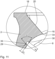
- FIG. 11 shows a further embodiment of the granulate groove 35, which is essentially according to the embodiment 3 corresponds, wherein the groove depth nt is increased, so that the granulate groove 35 has an approximately square cross-sectional area.
- the opening angle ⁇ is according to the embodiment in 3 chosen.
Landscapes
- Engineering & Computer Science (AREA)
- Mechanical Engineering (AREA)
- Filling Or Emptying Of Bunkers, Hoppers, And Tanks (AREA)
Description
Die Erfindung betrifft eine Zellenradschleuse für granulatförmiges Schüttgut.The invention relates to a star feeder for granular bulk material.
Die
Es ist eine Aufgabe der vorliegenden Erfindung, eine Zellenradschleuse mit verbessertem Einlaufverhalten für das granulatförmige Schüttgut zu schaffen, wobei insbesondere die Beschädigung des Schüttguts reduziert ist.It is an object of the present invention to create a star feeder with improved inflow behavior for the granular bulk material, with damage to the bulk material being reduced in particular.
Diese Aufgabe ist erfindungsgemäß gelöst durch eine Zellenradschleuse mit den im Anspruch 1 angegebenen Merkmalen.According to the invention, this object is achieved by a cellular wheel sluice having the features specified in claim 1 .
Erfindungsgemäß wurde erkannt, dass das Einlaufverhalten für Schüttgut in eine Zellenradschleuse verbessert werden kann, wenn eine Oberfläche am Einlaufschacht vergrößert ist. Erfindungsgemäß sind mindestens zwei erhabene Granulatdächer am Einlaufschacht angeordnet. Das jeweilige Granulatdach ist insbesondere nasenförmig ausgeführt.According to the invention, it was recognized that the inflow behavior for bulk material in a cellular wheel sluice can be improved if a surface on the inflow shaft is enlarged. According to the invention, at least two raised granulate roofs are arranged on the inlet shaft. The respective granulate roof is designed in particular in the form of a nose.
In einer Blickrichtung von oben in den Einlaufschacht ist das Granulatdach dreieckförmig ausgeführt. Das Granulatdach verbessert das Einlaufverhalten von granulatförmigem Schüttgut. Um eine Beschädigung des Schüttguts zu reduzieren, sind jeweils zwei Granulatnuten, die am Übergang zwischen zwei Granulatdächern und am Übergang zwischen einem Granulatdach und einer Einlaufkante jeweils angeordnet sind, in jeweils einem Schnittpunkt zusammengeführt. Als Einlaufkante werden Kanten am Einlaufschacht bezeichnet, über die Granulatkörner aus dem Einlaufschacht in die Zylinderbohrung des Gehäuses der Zellenradschleuse zugeführt werden. Die Einlaufkante ist insbesondere am Übergang zu dem Einlaufschacht angeordnet. Über die Einlaufkante kann das granulatförmige Schüttgut in die Kammer des Zellenrads gelangen. Damit wird erreicht, dass trotz der Erhöhung der Oberfläche im Einlaufschacht die Anzahl der Schnittpunkte nicht linear ansteigt. Erfindungsgemäß ist das Verhältnis von Oberfläche am Einlaufschacht bezogen auf die Anzahl der Schnittpunkte, insbesondere überproportional, erhöht. Eine Zellenradschleuse mit drei Granulatdächern weist insbesondere nur zwei Schnittpunkte auf.In a viewing direction from above into the inlet shaft, the granulate roof is designed in the shape of a triangle. The granulate roof improves the infeed behavior of granular bulk material. In order to reduce damage to the bulk material, two granulate grooves each arranged at the transition between two granulate roofs and at the transition between a granulate roof and an inlet edge are each brought together at an intersection point. Inlet edges are edges on the inlet shaft through which the granules are fed from the inlet shaft into the cylinder bore of the rotary valve housing. The inlet edge is arranged in particular at the transition to the inlet shaft. The granular bulk material can enter the cell wheel chamber via the inlet edge. This ensures that the number of intersection points does not increase linearly, despite the increase in surface area in the inlet shaft. According to the invention, the ratio of the surface area at the inlet shaft to the number of intersection points is increased, in particular disproportionately. In particular, a rotary valve with three granulate roofs has only two intersection points.
Mit der erfindungsgemäßen Zellenradschleuse ist die Förderleistung erhöht und das Schnittverhalten bzw. das Hackverhalten reduziert. Eine wesentliche Erkenntnis beruht darauf, dass eine Oberfläche eines groß ausgeführten Granulatdaches auf mehrere, vergleichsweise kleinere Granulatdächer aufgeteilt werden kann. Beispielsweise können zwei Granulatdächer, drei Granulatdächer, vier Granulatdächer oder fünf Granulatdächer oder mehr vorgesehen sein. Die Granulatdächer sind entlang einer Breite des Einlaufschachts nebeneinander angeordnet. Die Breite des Einlaufschachts ist parallel zur Drehachse des Zellenrads orientiert. Insbesondere beträgt die vergrößerte Oberfläche am Einlaufschacht zwischen 110 % und 150 % der Oberfläche einer Zellenradschleuse gleicher Bauart mit nur einem Granulatdach, insbesondere zwischen 120 % und 140 % und insbesondere zwischen 125 % und 135 %. Die erfindungsgemäße Schleuse kann auch bei hohen Drehzahlen, insbesondere Rotorumfangsgeschwindigkeiten von mindestens 1 m/s und insbesondere von mindestens 2 m/s, zuverlässig und fehlersicher befüllt werden. Der Füllgrad der einzelnen Kammern des Zellenrads ist verbessert. Der Massendurchsatz der Zellenradschleuse ist erhöht.With the cellular wheel sluice according to the invention, the conveying capacity is increased and the cutting behavior or chopping behavior is reduced. A key finding is based on the fact that a surface of a large granulate roof is divided into several comparatively smaller granulate roofs can be. For example, two granule roofs, three granule roofs, four granule roofs or five granule roofs or more can be provided. The roofs of granules are arranged side by side along a width of the manhole. The width of the inlet shaft is oriented parallel to the axis of rotation of the star feeder. In particular, the enlarged surface at the inlet shaft between 110% and 150% of the surface of a rotary valve of the same type with only one granulate roof, in particular between 120% and 140% and in particular between 125% and 135%. The lock according to the invention can be filled reliably and failsafe even at high speeds, in particular rotor peripheral speeds of at least 1 m/s and in particular of at least 2 m/s. The degree of filling of the individual chambers of the star feeder is improved. The mass throughput of the rotary valve is increased.
Das Gehäuse der Zellenradschleuse weist eine Zylinderbohrung auf, die auch als Innenraum der Zellenradschleuse bezeichnet wird.The housing of the cellular wheel sluice has a cylinder bore, which is also referred to as the interior of the cellular wheel sluice.
Eine Zellenradschleuse gemäß Anspruch 2 ermöglicht ein konstantes Abdrängungsverhalten des Zellenrades. Es wurde gefunden, dass für das Abdrängungsverhalten des Granulatkorns in der Granulatnut der Abdrängungswinkel ein relevanter Parameter ist, der insbesondere von der Drehposition des Zellenrades im Gehäuse der Zellenradschleuse abhängt. Es wurde gefunden, dass das konstante Abdrängungsverhalten erreicht wird, wenn der Abdrängungswinkel zumindest abschnittsweise konstant ist. Insbesondere ist der Abdrängungswinkel über mindestens 50 % der Gesamtlänge der Granulatnut, insbesondere über 60 % der Gesamtlänge der Granulatnut, insbesondere über 70 % der Gesamtlänge der Granulatnut, insbesondere über 80 % der Gesamtlänge der Granulatnut, insbesondere über 90 % der Gesamtlänge der Granulatnut, insbesondere über 95 % der Gesamtlänge der Granulatnut und insbesondere entlang der Gesamtlänge der Granulatnut konstant. Dadurch ist es möglich, den Gehäusewinkel, der für die Granulatnut erforderlich ist, zu verkleinern, um insbesondere den Einlaufquerschnitt der Zellenradschleuse zu vergrößern. Eine derartige Schleuse weist eine erhöhte Förderleistung auf.A cellular wheel sluice according to
Zusätzlich oder alternativ kann bei einer Zellenradschleuse gemäß Anspruch 3 der Abdrängungswinkel in Drehrichtung des Zellenrades zumindest abschnittsweise ansteigen. Der Anstieg kann beispielsweise linear oder progressiv erfolgen. Der Anstieg kann auch durchgängig entlang der gesamten Granulatnutlänge erfolgen. Beispielsweise kann der Abdrängungswinkel zu Beginn der Granulatnut mindestens 35° betragen und am Ende der Granulatnut, insbesondere am Schnittpunkt, höchstens 70° betragen. Eine derartige Granulatnut kann in einer Projektion in die horizontale Ebene aufgrund der gekrümmten Oberfläche an der Innenseite der Zylinderbohrung so erscheinen, als ob der Abdrängungswinkel konstant ist. Tatsächlich ist der Abdrängungswinkel aber abschnittsweise ansteigend in Drehrichtung des Zellenrads ausgeführt.Additionally or alternatively, in a cellular wheel sluice according to
Eine Zellenradschleuse gemäß Anspruch 4 weist ein verbessertes Förderverhalten auf. Ein Hacken der Granulatkörner ist im Wesentlichen verhindert.A cellular wheel sluice according to
Eine Granulatnut gemäß Anspruch 5 ermöglicht ein vorteilhaftes - Abdrängen des Schüttguts entlang der Granulatnut. Die Querschnittsfläche der Granulatnut ist im Wesentlichen beliebig wählbar. Die Querschnittsfläche kann quadratisch, rechteckig oder dreieckig, insbesondere mit abgerundeter Spitze, ausgeführt sein. Es sind auch andere, insbesondere abgerundete, Querschnittsformen für die Granulatnut denkbar.A granulate groove according to
Die Ausführung einer Granulatnut gemäß Anspruch 6 verbessert das Abdrängungsverhalten für das Granulatkorn in der Zellenradschleuse. Es wurde gefunden, dass eine scharfkantige Ausführung der Granulatnut vom Innenraum der Zellenradschleuse her gesehen vermieden werden soll.The design of a granulate groove according to
Eine Granulatnut gemäß Anspruch 7 ermöglicht eine vorteilhafte Herstellung des Gehäuses. Beim Gießen des Gehäuses kann insbesondere ein Kernteil eingespart werden.A granulate groove according to
Bei einer Zellenradschleuse gemäß Anspruch 8 ist das Risiko der Beschädigung des Granulatkorns zusätzlich reduziert. Die integrale Länge aller Granulatnuten ist vergrößert, so dass ein Gleiten der Granulatkörner entlang der Granulatnut bis zum Schnittpunkt vermieden werden kann.With a cellular wheel sluice according to
Alternativ ermöglicht eine Ausführung einer Zellenradschleuse gemäß Anspruch 9 eine erhöhte Förderleistung. Die Einlauffläche der Zellenradschleuse ist vergleichsweise groß und ermöglicht einen vergrößerten Schüttgutmassestrom in die Zellenradschleuse durch den Einlaufschacht.Alternatively, an embodiment of a cellular wheel sluice according to
Eine Zellenradschleuse gemäß Anspruch 10 ermöglicht eine verbesserte Abschiebewirkung auf das in den Einlaufschacht fallende granulatförmige Schüttgut. Die Wahrscheinlichkeit, dass ein Granulatkorn zwischen die Nasenspitze, also das vordere Ende des Granulatdachs, und den Zellenradsteg geraten kann, ist reduziert. Das Risiko, dass ein Hacken des Schüttguts an dieser Stelle erfolgt, ist reduziert.A cellular wheel sluice according to
Ausführungsbeispiele der Erfindung werden nachfolgend anhand der Zeichnung näher erläutert. In dieser zeigen:
- Fig. 1
- eine Draufsicht auf eine erfindungsgemäße Schleuse ohne Zellenrad mit Blick in den Einlaufschacht,
- Fig. 2
- eine Schnittdarstellung gemäß Schnittlinie II-II in
Fig. 1 , - Fig. 3
- eine vergrößerte Darstellung des Details III in
Fig. 2 , - Fig. 4
- eine Schnittdarstellung gemäß Schnittlinie IV-IV in
Fig. 2 , - Fig. 5
- eine Seitenansicht einer Zellenradschleuse gemäß einer weiteren Ausführungsform mit Kennzeichnung verschiedener Ansichtsebenen,
- Fig. 6
- eine Darstellung der Gehäuseinnenseite der Zellenradschleuse gemäß
Fig. 5 gemäß der Ansicht VI-VI - Fig. 7
- eine
Fig. 6 entsprechende Darstellung gemäß der Ansicht VII - VII inFig. 5 , - Fig. 8
- eine
Fig. 6 entsprechende Darstellung gemäß der Ansicht VIII - VIII inFig. 5 , - Fig. 9
- eine
Fig. 4 entsprechende Ansicht einer Zellenradschleuse gemäß einer weiteren Ausführungsform, - Fig. 10
- eine
Fig. 3 entsprechende Darstellung einer Granulatnut einer Zellenradschleuse gemäß einem weiteren Ausführungsbeispiel, - Fig. 11
- eine
Fig. 10 entsprechende Detaildarstellung einer Granulatnut einer Zellenradschleuse gemäß einer weiteren Ausführungsform.
- 1
- a top view of a lock according to the invention without a star feeder looking into the inlet shaft,
- 2
- a sectional view according to section line II-II in
1 , - 3
- an enlarged view of detail III in
2 , - 4
- a sectional view according to section line IV-IV in
2 , - figure 5
- a side view of a rotary valve according to a further embodiment with marking of different viewing levels,
- 6
- a representation of the inside of the housing of the rotary valve according to
figure 5 according to view VI-VI - 7
- one
6 corresponding representation according to view VII - VII infigure 5 , - 8
- one
6 corresponding representation according to view VIII - VIII infigure 5 , - 9
- one
4 corresponding view of a rotary valve according to another embodiment, - 10
- one
3 corresponding representation of a granulate groove of a rotary valve according to a further embodiment, - 11
- one
10 corresponding detailed representation of a granulate groove of a rotary valve according to a further embodiment.
Eine in
Die Zellenradschleuse 1 umfasst ein Gehäuse 2 mit einer zylindrischen Bohrung 3, in der koaxial ein Zellenrad 4 drehantreibbar um eine Drehachse 5 angeordnet ist. Die Zylinderbohrung 3 bildet den Innenraum des Gehäuses 2.The cellular wheel sluice 1 comprises a
Das Zellenrad 4 weist eine Zellenradwelle 6 und mehrere, bezüglich der Drehachse 5 an der Zellenradwelle 6 radial orientiert angebrachte Zellenradstege 7 auf. Die Zellenradstege 7 sind in Drehrichtung 8 um die Drehachse 5 jeweils gleich beabstandet zueinander angeordnet. Zwischen der Zellenradwelle 6, zwei benachbarten Zellenradstegen 7 und einer inneren Mantelfläche 9 der Zylinderbohrung 3 wird eine Zellenradkammer 10 begrenzt, in die das granulatförmige Schüttgut zur Förderung dosiert wird.The
Gemäß dem gezeigten Ausführungsbeispiel weist das Zellenrad 4 zwölf Zellenradstege 7 auf, so dass zwölf Zellenradkammern 10 gebildet sind. Die Anzahl der Zellenradstege 7 kann je nach Einsatzzweck des Zellenrads 4 größer oder kleiner gewählt werden, um entsprechend eine feinere oder gröbere Aufteilung der Zellenradkammern 10 einzustellen.According to the exemplary embodiment shown, the
Das Gehäuse 2 ist stirnseitig entlang der Drehachse 5 mit jeweils einem nicht dargestellten Seitendeckel abgedichtet verschließbar. Dazu weist das Gehäuse 2 jeweils einen stirnseitig angeordneten, am Gehäuse 2 integriert ausgeführten Verbindungsflansch 12 auf. An dem Verbindungs- oder Seitenflansch 12 sind mehrere, nicht gezeigte Befestigungsbohrungen vorgesehen, um den Gehäusedeckel am Seitenflansch 12 mittels Befestigungsschrauben lösbar und abgedichtet anzubringen. Dazu kann zwischen dem Seitenflansch 12 und dem Seitendeckel eine Dichtung, insbesondere ein O-Ring oder eine Flachdichtung, angeordnet sein.The
An der Außenseite des Gehäuses 2 ist ein Leckluftstutzen 17 angeordnet, der über einen Leckluftkanal 28 mit der Zylinderbohrung 3 verbunden ist. Der Leckluftkanal 28 kann bereichsweise zwei parallel zueinander verlaufende Stränge aufweisen, die in
Das Gehäuse 2 weist einen Einlaufschacht 14 auf, über den das Schüttgut der Zellenradschleuse 1, insbesondere der Zylinderbohrung 3, mit dem Zellenrad 4 zugeführt wird. In einer Einbauposition der Zellenradschleuse 1, wie in
An seinem oberen Ende weist der Einlaufschacht 14 einen Verbindungsflansch 18 auf, der entsprechend den stirnseitig angeordneten Verbindungsflanschen 12 ausgeführt ist. An dem Verbindungsflansch 18 des Einlaufschachts 14 sind gemäß dem gezeigten Ausführungsbeispiel sechszehn Befestigungsbohrungen 13 vorgesehen.At its upper end, the
An dem Einlaufschacht 14, insbesondere entlang der Einlaufschräge 15, sind drei nasenförmige Granulatdächer 19 angeordnet. Die Granulatdächer 19 sind gegenüber der Einlaufschräge 15 erhaben ausgeführt. Die Granulatdächer 19 bewirken eine Vergrößerung der Oberfläche der Einlaufschräge 15 im Einlaufschacht 14. Die Granulatdächer 19 sind in der Art eines gleichseitigen Satteldaches an der Einlaufschräge 15 angeordnet. Die Granulatdächer 19 erstrecken sich von der Einlaufschräge 15 gaubenartig. Jedes Granulatdach 19 weist einen First 20 und zwei jeweils mit einem Neigungswinkel η gegenüber einer Vertikalebene, die insbesondere senkrecht zur Drehachse 5 orientiert ist, geneigt angeordneten Langfläche 21 auf. Die freien Kanten der Langflächen 21, die der Einlaufschräge 15 abgewandt angeordnet sind, werden als Abweiskanten 22 bezeichnet. Die Abweiskante 22 wird auch als Einlaufkante bezeichnet.At the
Die Granulatdächer 19 erstrecken sich an der Einlaufschräge 15 im Einlaufschacht 14 bis zur Zellenradbohrung 3, wie dies insbesondere in
Die Granulatdächer 19 sind entlang der Breitenrichtung, also in einer Richtung parallel zur Drehachse 5, nebeneinander angeordnet. Die Granulatdächer 19 sind an der Einlaufschräge 15 derart angeordnet, dass der jeweilige First 20 quer und insbesondere senkrecht zur Drehachse 5 orientiert ist.The
In jeweils einem Übergangsbereich zwischen zwei benachbarten Granulatdächern 19 ist eine erste Granulatnut 23 ausgebildet. Die erste Granulatnut 23 ist insbesondere als nutartige Vertiefung an einer virtuellen Stoßkante der jeweiligen Langflächen 21 der benachbarten Granulatdächer 19 angeordnet. Jeweils an einer Außenseite der außenliegenden Granulatdächer 19, also in einem Übergangsbereich zwischen dem jeweils außenliegenden Granulatdach 19 und einer inneren Begrenzungswand des Einlaufschachts 14, ist eine zweite Granulatnut 24 angeordnet, die im Wesentlichen identisch zu der ersten Granulatnut 23 ausgeführt ist. Die Begrenzungswand weist eine obere, dem Einlaufschacht 14 zugewandte Begrenzungskante 25 auf. Die Begrenzungskante 25 bildet eine Einlaufkante.A
Die Granulatnuten 23, 24 sind jeweils als nutförmige Vertiefung an der Mantelfläche 9 der Zylinderbohrung 3 ausgeführt. Die Granulatnuten 23, 24 erstrecken sich in Drehrichtung 8 des Zellenrades 4. Jeweils zwei Granulatnuten 23, 24 laufen in einem Schnittpunkt 26 zusammen. Der Schnittpunkt 26 ist nicht als Punkt im geometrischen Sinne zu verstehen. Es handelt sich hierbei um die Verbindungsstelle zweier Nuten, insbesondere ein Verbindungsbereich, beispielsweise eine Schnittebene und/oder eine Kante, wie insbesondere in
Dadurch, dass die Granulatnuten 23, 24 jeweils paarweise zu einem Schnittpunkt 26 zusammengeführt sind, ist die Anzahl der Schnittpunkte, nämlich zwei, insbesondere bezogen auf die Gesamt-Anzahl der Granulatdächer 19, nämlich drei, reduziert. Die Zellenradschleuse 1 optimiert die Anzahl der Granulatdächer 19 zu der der Schnittpunkte 26.Due to the fact that the
Gemäß dem gezeigten Ausführungsbeispiel ist die Oberfläche im Bereich des Einlaufschachts durch die Granulatdächer 19 um mindestens 20 %, insbesondere mindestens 25 % und insbesondere mindestens 30 % gegenüber einer vergleichbaren Zellenradschleuse mit nur einem Granulatdach vergrößert.According to the exemplary embodiment shown, the surface area in the area of the inlet shaft is increased by the
Gemäß dem gezeigten Ausführungsbeispiel sind sämtliche Granulatdächer 19 identisch ausgeführt. Die Abweiskanten 22 eines Granulatdaches 19 weisen jeweils gleiche Längen 1 auf. Die Abweiskanten 22 der verschiedenen Granulatdächer 19 weisen ebenfalls gleiche Längen 1 auf. Insbesondere sind die Granulatdächer 19 entlang der Drehachse 5 gleich verteilt angeordnet. Das bedeutet, dass die Abweiskanten 22, die vom Einlaufschacht 14 zu den jeweils außen angeordneten Granulatdächern 19 angeordnet sind, eine identische Länge 1 aufweisen wie die Längen der Abweiskanten 22 der Granulatdächer 19 selbst. Die Granulatdächer 19 sind entlang der Drehachse 5 gleichverteilt angeordnet. Durch diese Ausführung sind die Granulatdächer 19 vergleichsweise größer ausgeführt, weisen also eine größere Dachfläche auf. Entsprechend sind die Granulatnuten 23, 24 vergleichsweise länger ausgeführt, so dass das Hackverhalten der Zellenradschleuse 1 zusätzlich verbessert ist. Das Risiko, dass Granulatkörner beim Eintritt in die Zellenradschleuse 1, insbesondere in die Zylinderbohrung 3, gequetscht oder geschnitten werden, ist reduziert.According to the embodiment shown, all
In der Schnittdarstellung gemäß
Insbesondere ist die minimale lichte Weite der Granulatnut 23, 24, die gemäß dem gezeigten Ausführungsbeispiel der Nuttiefe nt entspricht, größer als der größte Partikeldurchmesser der Granulatkörner. Dadurch ist ein freier Transport der Granulatkörner entlang der Granulatnut 23, 24 gewährleistet.In particular, the minimum clear width of the
Gemäß dem gezeigten Ausführungsbeispiel weist die Granulatnut 23, 24 entlang des Nutverlaufs eine konstante Querschnittsfläche auf.According to the exemplary embodiment shown, the
Die Granulatnut 23, 24 ist, insbesondere am Schnittpunkt 26, mit einem Öffnungswinkel β gegenüber der Zylinderbohrung 3 des Gehäuses 2 angeordnet, wobei der Öffnungswinkel kleiner oder gleich 120° beträgt. Vorteilhaft ist es, wenn der Öffnungswinkel zwischen 80° und 120° beträgt, insbesondere zwischen 90° und 110°.The
Der Öffnungswinkel β wird durch die in Drehrichtung 8 hintere Seitenkante 29 der Granulatnut 23, 24 und der Tangente 30 an der Mantelfläche der Zylinderbohrung 3 am Schnittpunkt mit der hinteren Seitenkante 29 definiert.The opening angle β is defined by the
An einer Unterseite des Gehäuses 2 weist die Zellenradschleuse 1 einen Auslaufschacht 31 auf. Der Einlaufschacht 14 und der Auslaufschacht 31 sind bezüglich der Drehachse 5 gegenüberliegend zueinander angeordnet. Über den Auslaufschacht 31 kann das mittels des Zellenrads 4 dosiert geförderte Schüttgut aus der Zellenradschleuse 1 abgegeben werden. Zur Verbindung der Zellenradschleuse 1 mit Förderkomponenten und/oder -leitungen weist das Gehäuse 2 stirnseitig unten am Auslaufschacht 31 einen weiteren Verbindungsflansch 18 auf, der im Wesentlichen identisch mit dem Verbindungsflansch 18 am Einlaufschacht 14 ausgeführt ist.The star feeder 1 has an
Nachfolgend wird anhand von
Es wurde gefunden, dass es vorteilhaft ist, wenn der Abdrängungswinkel α größer oder gleich 30° ist. Besonders vorteilhaft ist es, wenn der Abdrängungswinkel α unabhängig von der Drehposition des Zellenrades 4 größer oder gleich 30° ist. Gemäß dem gezeigten Ausführungsbeispiel ist der Abdrängungswinkel α unabhängig von der Drehposition des Zellenrades 45°. Der Abdrängungswinkel α kann auch größer oder kleiner als 45° sein.It has been found that it is advantageous if the deflection angle α is greater than or equal to 30°. It is particularly advantageous if the deflection angle α is greater than or equal to 30°, regardless of the rotational position of the
Insbesondere wurde gefunden, dass es nicht erforderlich ist, dass der Abdrängungswinkel α in der Draufsicht auf die Granulatnut 23, 24 und/oder die Abweiskante 22 einen konstanten Verlauf hat. Insbesondere kann der Abdrängungswinkel α sich in der Granulatnut 23, 24, zum Schnittpunkt 26 hin, kontinuierlich vergrößern.In particular, it was found that it is not necessary for the deflection angle α to have a constant profile in the top view of the
Insbesondere ist der Abdrängungswinkel α für alle Abweiskanten 22 ähnlich und insbesondere identisch. Ein ähnlicher Abdrängungswinkel α bedeutet, dass Winkelabweichungen zwischen verschiedenen Abdrängungswinkeln α höchstenst 5°, insbesondere höchstens 3° und insbesondere höchstens 1° betragen. Das bedeutet, dass im Einlaufschacht 14 alle Abweiskanten 22 gleich, insbesondere identisch definiert sind. Die Abweiskanten 22 laufen insbesondere in Drehrichtung 8 des Zellenrades 4.In particular, the deflection angle α is similar for all deflecting
Bei der gezeigten Zellenradschleuse 1 ist es somit möglich, den Abdrängungswinkel α zu reduzieren. Dadurch, dass der Abdrängungswinkel α reduziert ist und insbesondere kleiner ist als 45°, ist die Einlauföffnung vergrößert. Dadurch kann die Zellenradschleuse 1 mit erhöhtem Durchsatz, also mit mehr Leistung, betrieben werden.In the case of the rotary feeder 1 shown, it is thus possible to reduce the deflection angle α. Due to the fact that the deflection angle α is reduced and in particular is smaller than 45°, the inlet opening is enlarged. As a result, the cellular wheel sluice 1 can be operated with an increased throughput, ie with more power.
Ein Mittenabstand M der vorderen Spitzen 33 der Einlaufschrägen 19 von der Drehachse 5 ist gemäß diesem Ausführungsbeispiel vergleichsweise Groß gegenüber einer aus der
Bei der Zellenradschleuse 1 sind die Granulatdächer 32 vergleichsweise kleiner ausgeführt. Das bedeutet, dass die Länge 1 der Abweiskanten 22 der Granulatdächer 32 kleiner ist als bei dem vorherigen Ausführungsbeispiel. Zudem ist ein seitlicher Abstand A der Abweiskanten 22 der Granulatdächer 32 zu der seitlichen Einlaufkante 25 größer als die jeweilige Länge 1 der Abweisenkanten 22. Insbesondere gilt: A ≥ 1,5 · 1, insbesondere A ≥ 2 · 1 und insbesondere A ≥ 2,5 · 1.In the cellular wheel sluice 1, the
Bei dem gezeigten Ausführungsbeispiel beträgt der Mittenabstand M zu der vorderen Spitze 33 von der Drehachse 5 mindestens 0,45 · r. Insbesondere gilt: M ≥ 0,48 · r, insbesondere M ≥ 0,5 · r und insbesondere M ≥ 0,525 · r.In the exemplary embodiment shown, the center distance M to the
Bei dieser Ausführungsform ist die Einlauföffnung 16 zu einem größeren Anteil freigegeben. Das bedeutet, dass die freie Durchströmfläche der Einlauföffnung 16 bei diesem Ausführungsbeispiel vergrößert ist. Die Leitungsfähigkeit dieser Zellenradschleuse ist vergrößert.In this embodiment, the
Gemäß dem gezeigten Ausführungsbeispiel in
Der Öffnungswinkel β ist entsprechend dem Ausführungsbeispiel in
Claims (10)
- Cellular wheel sluice for granulate bulk product, with a housing (2) in which a cellular wheel (4) is rotatably mounted, wherein the housing (2) has an inlet shaft (14) for the bulk product, wherein at least two raised granulate roofs (19; 32) are arranged at the inlet shaft (14),
characterized in that- a granulate groove (23, 24; 35) is arranged in each case at the transition between two granulate roofs (19; 32) and at the transition between one granulate roof (19; 32) and an inlet edge (22, 25),- two granulate grooves (23, 24; 35) in each case run together at an intersection point (26) in the rotation direction of the cellular wheel (4). - Cellular wheel sluice according to claim 1, characterized in that a displacement angle (α) enclosed between the granulate groove (23, 24; 35) and a cellular wheel web (7) is constant at least in portions irrespective of the rotary position of the cellular wheel (4).
- Cellular wheel sluice according to one of the preceding claims, characterized in that a displacement angle (α) enclosed between the granulate groove (23, 24; 35) and a cellular wheel web (7) increases at least in portions in the rotation direction (8) of the cellular wheel (4).
- Cellular wheel sluice according to claim 2 or 3, characterized in that for the displacement angle (α): 30° ≤ α ≤ 90°, in particular 30° ≤ α ≤ 80°, in particular 30° ≤ α ≤ 70°, in particular 30° ≤ α ≤ 60°, in particular 35° ≤ α ≤ 50° and in particular 40° ≤ α ≤ 45°.
- Cellular wheel sluice according to any of the preceding claims, characterized in that the granulate groove (23, 24; 35) has a constant cross-sectional area along the groove course.
- Cellular wheel sluice according to any of the preceding claims, characterized in that the granulate groove (23, 24; 35) has an opening angle (β) oriented relative to an interior (3) of the housing (2), wherein 80° ≤ β ≤ 120°, in particular 90° ≤ β ≤ 110°.
- Cellular wheel sluice according to any of the preceding claims, characterized in that the granulate groove (23, 24; 35) has a demoulding chamfer (ε) facing the interior (3) of the housing (2).
- Cellular wheel sluice according to any of the preceding claims, characterized in that deflection edges (22) of the granulate roofs (19) have the same lengths (1) and in particular are evenly distributed in a transverse direction which is oriented in particular parallel to the rotation axis (5) of the cellular wheel (4).
- Cellular wheel sluice according to any of claims 1 to 7, characterized in that a lateral distance (A) of deflection edges (22) of the granulate roofs (32) from the lateral inlet edge (25) is greater than the length (1) of the deflection edges (22).
- Cellular wheel sluice according to any of the preceding claims, characterized in that the granulate roof (19; 32) is tilted continuously relative to a vertical plane, wherein the granulate roof (19; 32) in particular extends up to the cylinder bore (3) of the housing (2).
Applications Claiming Priority (1)
| Application Number | Priority Date | Filing Date | Title |
|---|---|---|---|
| DE102018216654.4A DE102018216654B3 (en) | 2018-09-27 | 2018-09-27 | Cell wheel lock for granular bulk material |
Publications (2)
| Publication Number | Publication Date |
|---|---|
| EP3628611A1 EP3628611A1 (en) | 2020-04-01 |
| EP3628611B1 true EP3628611B1 (en) | 2023-07-12 |
Family
ID=67840911
Family Applications (1)
| Application Number | Title | Priority Date | Filing Date |
|---|---|---|---|
| EP19194524.5A Active EP3628611B1 (en) | 2018-09-27 | 2019-08-30 | Cellular wheel lock for granular bulk material |
Country Status (10)
| Country | Link |
|---|---|
| US (1) | US10954083B2 (en) |
| EP (1) | EP3628611B1 (en) |
| CN (1) | CN110950091B (en) |
| DE (1) | DE102018216654B3 (en) |
| DK (1) | DK3628611T3 (en) |
| ES (1) | ES2957340T3 (en) |
| FI (1) | FI3628611T3 (en) |
| HU (1) | HUE063972T2 (en) |
| PL (1) | PL3628611T3 (en) |
| PT (1) | PT3628611T (en) |
Family Cites Families (24)
| Publication number | Priority date | Publication date | Assignee | Title |
|---|---|---|---|---|
| US2852315A (en) * | 1956-10-05 | 1958-09-16 | Fuller Co | Material feeder |
| US3052383A (en) * | 1959-12-28 | 1962-09-04 | Sherman T Transeau | Rotary feeder mechanism |
| US3118575A (en) * | 1960-12-19 | 1964-01-21 | Braun & Co C F | Feeder for solid particles |
| US3260420A (en) * | 1964-07-28 | 1966-07-12 | Richards Structural Steel Comp | Motor driven rotary dispensing valve |
| DE2107948C3 (en) * | 1971-02-19 | 1976-01-02 | Claudius Peters Ag, 2000 Hamburg | Rotary feeder for free-flowing goods such as plastic granulate |
| DE2806059C2 (en) * | 1978-02-14 | 1983-09-15 | Johann Ing.(grad.) 6800 Mannheim Grüner | Rotary valve |
| US4537333A (en) * | 1981-07-20 | 1985-08-27 | Eli Lilly And Company | Airborne particle dispenser |
| DE3445710A1 (en) * | 1984-12-14 | 1986-06-19 | Waeschle Maschinenfabrik Gmbh, 7980 Ravensburg | CELL WHEEL LOCK FOR GRANULATED SCHUETTGUETER |
| JPH0324506Y2 (en) * | 1985-09-09 | 1991-05-28 | ||
| FR2587081B1 (en) * | 1985-09-11 | 1988-04-15 | Bp Chimie Sa | ROTARY-TYPE DOSING DEVICE FOR DELIVERING GRANULAR SUBSTANCES |
| DE3711084A1 (en) * | 1987-04-02 | 1988-10-13 | Buehler Miag Gmbh | Cellular wheel sluice |
| DE4004415C1 (en) * | 1990-02-13 | 1990-12-13 | Waeschle Maschinenfabrik Gmbh, 7980 Ravensburg, De | Sliding vane closure for granular bulk material - has deflector body, filling pocket-shaped recess, formed by scraper edge sections on housing inner wall |
| JPH0732510Y2 (en) * | 1990-04-26 | 1995-07-26 | 日本アルミニウム工業株式会社 | Bite prevention rotary valve |
| US5320258A (en) * | 1991-05-09 | 1994-06-14 | Paul Kermit D | Inlet port for rotary feeders |
| DE4135593C2 (en) * | 1991-10-29 | 2003-07-03 | Avt Anlagen Verfahrenstech | rotary |
| DE4228014C1 (en) * | 1992-08-24 | 1993-08-19 | Waeschle Maschinenfabrik Gmbh, 7980 Ravensburg, De | |
| DE102004001965B4 (en) * | 2004-01-13 | 2014-06-18 | Schenck Process Gmbh | rotary |
| US20100237267A1 (en) * | 2009-03-18 | 2010-09-23 | Shao Lu Chuang | Rotor Configuration for a Rotary Valve |
| US8944295B2 (en) * | 2011-12-12 | 2015-02-03 | Pelletron Corporation | Rotary valve with product relief grooves |
| JP5856037B2 (en) * | 2012-10-25 | 2016-02-09 | 株式会社ヨシカワ | Metering feeder |
| DE102014007480B4 (en) * | 2014-04-17 | 2024-02-29 | Zeppelin Systems Gmbh | Blow-out device for a rotary valve |
| CN106429249A (en) * | 2016-10-11 | 2017-02-22 | 合肥旭龙机械有限公司 | Rotary-unloading inlet/outlet anti-blockage structure |
| CN107380928A (en) * | 2017-08-15 | 2017-11-24 | 江苏万力机械股份有限公司 | A kind of Impeller powder feeder |
| CN108128641B (en) * | 2018-01-19 | 2023-07-28 | 武汉大坦智能装备科技有限公司 | High-speed implantation device for particulate matters |
-
2018
- 2018-09-27 DE DE102018216654.4A patent/DE102018216654B3/en active Active
-
2019
- 2019-08-30 FI FIEP19194524.5T patent/FI3628611T3/en active
- 2019-08-30 PL PL19194524.5T patent/PL3628611T3/en unknown
- 2019-08-30 HU HUE19194524A patent/HUE063972T2/en unknown
- 2019-08-30 PT PT191945245T patent/PT3628611T/en unknown
- 2019-08-30 EP EP19194524.5A patent/EP3628611B1/en active Active
- 2019-08-30 ES ES19194524T patent/ES2957340T3/en active Active
- 2019-08-30 DK DK19194524.5T patent/DK3628611T3/en active
- 2019-09-26 CN CN201910919183.XA patent/CN110950091B/en active Active
- 2019-09-26 US US16/584,018 patent/US10954083B2/en active Active
Also Published As
| Publication number | Publication date |
|---|---|
| DE102018216654B3 (en) | 2020-02-13 |
| US20200102159A1 (en) | 2020-04-02 |
| PT3628611T (en) | 2023-09-28 |
| FI3628611T3 (en) | 2023-10-04 |
| PL3628611T3 (en) | 2023-12-27 |
| CN110950091B (en) | 2022-07-12 |
| EP3628611A1 (en) | 2020-04-01 |
| ES2957340T3 (en) | 2024-01-17 |
| CN110950091A (en) | 2020-04-03 |
| HUE063972T2 (en) | 2024-02-28 |
| DK3628611T3 (en) | 2023-10-09 |
| US10954083B2 (en) | 2021-03-23 |
Similar Documents
| Publication | Publication Date | Title |
|---|---|---|
| DE4109467C2 (en) | Document shredder | |
| EP3746278B1 (en) | Internal mixer | |
| AT402726B (en) | CELL WHEEL LOCK FOR GRANULATED BULK MATERIALS | |
| DE4004415C1 (en) | Sliding vane closure for granular bulk material - has deflector body, filling pocket-shaped recess, formed by scraper edge sections on housing inner wall | |
| DE4113256A1 (en) | ANTI-CATCHING MECHANISM FOR A TURNTABLE WITH CONTINUOUS VOLUME OUTLET MATERIALS | |
| DE69200303T2 (en) | Adjusting lever for a stator blade. | |
| WO2020099684A1 (en) | Degassing extruder having a multi-screw unit and method for degassing polymer melts therewith | |
| EP2168893B1 (en) | Cellular rotary valve with grinding device | |
| EP1707042B1 (en) | Two-discs-spreader for granular material, in particular fertilizer, salt or the like | |
| WO2002038359A1 (en) | Ring extruder feed | |
| EP3628611B1 (en) | Cellular wheel lock for granular bulk material | |
| EP3342480B1 (en) | Mixer comprising mixing tool | |
| DE4135593C2 (en) | rotary | |
| DE19844112A1 (en) | Bucket ring for airflow roller mills | |
| WO2013072066A1 (en) | Milling device for milling off road surfaces or for removing ground material, and deflection roller for a conveyor belt for a milling device of this type | |
| EP1330951B1 (en) | Apparatus for mixing feed | |
| EP3057808B1 (en) | Granular material discharge device | |
| DE102005046043B4 (en) | Mounting arrangement of a knife blade on a mixing screw of a feed mixer wagon | |
| DE19805489C1 (en) | Distributor for pelletised fertiliser | |
| DE19612887A1 (en) | Pipe bend for pipes feeding liquids or gases | |
| DE3703309C2 (en) | ||
| EP4311882B1 (en) | Slurry wall cutter and method for creating a milled slot in the ground | |
| DE19813867C2 (en) | Device for producing solid and / or solid-liquid mixtures | |
| EP1006064A1 (en) | Cellular rotary valve | |
| EP2014834A2 (en) | Spinnerdisc for Winterservice-Spreading-Apparatus |
Legal Events
| Date | Code | Title | Description |
|---|---|---|---|
| PUAI | Public reference made under article 153(3) epc to a published international application that has entered the european phase |
Free format text: ORIGINAL CODE: 0009012 |
|
| STAA | Information on the status of an ep patent application or granted ep patent |
Free format text: STATUS: THE APPLICATION HAS BEEN PUBLISHED |
|
| STAA | Information on the status of an ep patent application or granted ep patent |
Free format text: STATUS: REQUEST FOR EXAMINATION WAS MADE |
|
| AK | Designated contracting states |
Kind code of ref document: A1 Designated state(s): AL AT BE BG CH CY CZ DE DK EE ES FI FR GB GR HR HU IE IS IT LI LT LU LV MC MK MT NL NO PL PT RO RS SE SI SK SM TR |
|
| AX | Request for extension of the european patent |
Extension state: BA ME |
|
| 17P | Request for examination filed |
Effective date: 20200317 |
|
| RBV | Designated contracting states (corrected) |
Designated state(s): AL AT BE BG CH CY CZ DE DK EE ES FI FR GB GR HR HU IE IS IT LI LT LU LV MC MK MT NL NO PL PT RO RS SE SI SK SM TR |
|
| GRAP | Despatch of communication of intention to grant a patent |
Free format text: ORIGINAL CODE: EPIDOSNIGR1 |
|
| STAA | Information on the status of an ep patent application or granted ep patent |
Free format text: STATUS: GRANT OF PATENT IS INTENDED |
|
| INTG | Intention to grant announced |
Effective date: 20230202 |
|
| GRAS | Grant fee paid |
Free format text: ORIGINAL CODE: EPIDOSNIGR3 |
|
| RBV | Designated contracting states (corrected) |
Designated state(s): AL AT BE BG CH CY CZ DK EE ES FI FR GB GR HR HU IE IS IT LI LT LU LV MC MK MT NL NO PL PT RO RS SE SI SK SM TR |
|
| REG | Reference to a national code |
Ref country code: DE Ref legal event code: R108 |
|
| GRAA | (expected) grant |
Free format text: ORIGINAL CODE: 0009210 |
|
| STAA | Information on the status of an ep patent application or granted ep patent |
Free format text: STATUS: THE PATENT HAS BEEN GRANTED |
|
| P01 | Opt-out of the competence of the unified patent court (upc) registered |
Effective date: 20230505 |
|
| AK | Designated contracting states |
Kind code of ref document: B1 Designated state(s): AL AT BE BG CH CY CZ DK EE ES FI FR GB GR HR HU IE IS IT LI LT LU LV MC MK MT NL NO PL PT RO RS SE SI SK SM TR |
|
| REG | Reference to a national code |
Ref country code: CH Ref legal event code: EP |
|
| REG | Reference to a national code |
Ref country code: IE Ref legal event code: FG4D Free format text: LANGUAGE OF EP DOCUMENT: GERMAN |
|
| REG | Reference to a national code |
Ref country code: SE Ref legal event code: TRGR |
|
| REG | Reference to a national code |
Ref country code: NL Ref legal event code: FP |
|
| REG | Reference to a national code |
Ref country code: PT Ref legal event code: SC4A Ref document number: 3628611 Country of ref document: PT Date of ref document: 20230928 Kind code of ref document: T Free format text: AVAILABILITY OF NATIONAL TRANSLATION Effective date: 20230921 |
|
| REG | Reference to a national code |
Ref country code: DK Ref legal event code: T3 Effective date: 20231003 |
|
| REG | Reference to a national code |
Ref country code: NO Ref legal event code: T2 Effective date: 20230712 |
|
| PGFP | Annual fee paid to national office [announced via postgrant information from national office to epo] |
Ref country code: TR Payment date: 20230913 Year of fee payment: 5 Ref country code: NO Payment date: 20230825 Year of fee payment: 5 Ref country code: IE Payment date: 20230829 Year of fee payment: 5 Ref country code: GB Payment date: 20230822 Year of fee payment: 5 Ref country code: FI Payment date: 20230822 Year of fee payment: 5 Ref country code: ES Payment date: 20230918 Year of fee payment: 5 Ref country code: CH Payment date: 20230902 Year of fee payment: 5 |
|
| REG | Reference to a national code |
Ref country code: LT Ref legal event code: MG9D |
|
| PGFP | Annual fee paid to national office [announced via postgrant information from national office to epo] |
Ref country code: SE Payment date: 20230822 Year of fee payment: 5 Ref country code: FR Payment date: 20230823 Year of fee payment: 5 Ref country code: BE Payment date: 20230822 Year of fee payment: 5 |
|
| REG | Reference to a national code |
Ref country code: GR Ref legal event code: EP Ref document number: 20230401747 Country of ref document: GR Effective date: 20231113 |
|
| REG | Reference to a national code |
Ref country code: SK Ref legal event code: T3 Ref document number: E 42417 Country of ref document: SK |
|
| PGFP | Annual fee paid to national office [announced via postgrant information from national office to epo] |
Ref country code: SK Payment date: 20230905 Year of fee payment: 5 |
|
| REG | Reference to a national code |
Ref country code: ES Ref legal event code: FG2A Ref document number: 2957340 Country of ref document: ES Kind code of ref document: T3 Effective date: 20240117 |
|
| PGFP | Annual fee paid to national office [announced via postgrant information from national office to epo] |
Ref country code: GR Payment date: 20231003 Year of fee payment: 5 |
|
| PG25 | Lapsed in a contracting state [announced via postgrant information from national office to epo] |
Ref country code: IS Free format text: LAPSE BECAUSE OF FAILURE TO SUBMIT A TRANSLATION OF THE DESCRIPTION OR TO PAY THE FEE WITHIN THE PRESCRIBED TIME-LIMIT Effective date: 20231112 |
|
| PG25 | Lapsed in a contracting state [announced via postgrant information from national office to epo] |
Ref country code: RS Free format text: LAPSE BECAUSE OF FAILURE TO SUBMIT A TRANSLATION OF THE DESCRIPTION OR TO PAY THE FEE WITHIN THE PRESCRIBED TIME-LIMIT Effective date: 20230712 Ref country code: LV Free format text: LAPSE BECAUSE OF FAILURE TO SUBMIT A TRANSLATION OF THE DESCRIPTION OR TO PAY THE FEE WITHIN THE PRESCRIBED TIME-LIMIT Effective date: 20230712 Ref country code: LT Free format text: LAPSE BECAUSE OF FAILURE TO SUBMIT A TRANSLATION OF THE DESCRIPTION OR TO PAY THE FEE WITHIN THE PRESCRIBED TIME-LIMIT Effective date: 20230712 Ref country code: IS Free format text: LAPSE BECAUSE OF FAILURE TO SUBMIT A TRANSLATION OF THE DESCRIPTION OR TO PAY THE FEE WITHIN THE PRESCRIBED TIME-LIMIT Effective date: 20231112 Ref country code: HR Free format text: LAPSE BECAUSE OF FAILURE TO SUBMIT A TRANSLATION OF THE DESCRIPTION OR TO PAY THE FEE WITHIN THE PRESCRIBED TIME-LIMIT Effective date: 20230712 |
|
| PGFP | Annual fee paid to national office [announced via postgrant information from national office to epo] |
Ref country code: PT Payment date: 20231019 Year of fee payment: 5 Ref country code: IT Payment date: 20231103 Year of fee payment: 5 Ref country code: HU Payment date: 20230911 Year of fee payment: 5 Ref country code: DK Payment date: 20231018 Year of fee payment: 5 Ref country code: CZ Payment date: 20230830 Year of fee payment: 5 |
|
| REG | Reference to a national code |
Ref country code: HU Ref legal event code: AG4A Ref document number: E063972 Country of ref document: HU |
|
| PGFP | Annual fee paid to national office [announced via postgrant information from national office to epo] |
Ref country code: PL Payment date: 20230726 Year of fee payment: 5 |
|
| PG25 | Lapsed in a contracting state [announced via postgrant information from national office to epo] |
Ref country code: LU Free format text: LAPSE BECAUSE OF NON-PAYMENT OF DUE FEES Effective date: 20230830 |
|
| PG25 | Lapsed in a contracting state [announced via postgrant information from national office to epo] |
Ref country code: SM Free format text: LAPSE BECAUSE OF FAILURE TO SUBMIT A TRANSLATION OF THE DESCRIPTION OR TO PAY THE FEE WITHIN THE PRESCRIBED TIME-LIMIT Effective date: 20230712 Ref country code: RO Free format text: LAPSE BECAUSE OF FAILURE TO SUBMIT A TRANSLATION OF THE DESCRIPTION OR TO PAY THE FEE WITHIN THE PRESCRIBED TIME-LIMIT Effective date: 20230712 Ref country code: LU Free format text: LAPSE BECAUSE OF NON-PAYMENT OF DUE FEES Effective date: 20230830 Ref country code: EE Free format text: LAPSE BECAUSE OF FAILURE TO SUBMIT A TRANSLATION OF THE DESCRIPTION OR TO PAY THE FEE WITHIN THE PRESCRIBED TIME-LIMIT Effective date: 20230712 Ref country code: MC Free format text: LAPSE BECAUSE OF FAILURE TO SUBMIT A TRANSLATION OF THE DESCRIPTION OR TO PAY THE FEE WITHIN THE PRESCRIBED TIME-LIMIT Effective date: 20230712 |
|
| PLBE | No opposition filed within time limit |
Free format text: ORIGINAL CODE: 0009261 |
|
| STAA | Information on the status of an ep patent application or granted ep patent |
Free format text: STATUS: NO OPPOSITION FILED WITHIN TIME LIMIT |
|
| 26N | No opposition filed |
Effective date: 20240415 |
|
| PG25 | Lapsed in a contracting state [announced via postgrant information from national office to epo] |
Ref country code: SI Free format text: LAPSE BECAUSE OF FAILURE TO SUBMIT A TRANSLATION OF THE DESCRIPTION OR TO PAY THE FEE WITHIN THE PRESCRIBED TIME-LIMIT Effective date: 20230712 |
|
| PGFP | Annual fee paid to national office [announced via postgrant information from national office to epo] |
Ref country code: NL Payment date: 20240821 Year of fee payment: 6 |