EP3628167A1 - Coating apparatus with gap - Google Patents
Coating apparatus with gap Download PDFInfo
- Publication number
- EP3628167A1 EP3628167A1 EP19196638.1A EP19196638A EP3628167A1 EP 3628167 A1 EP3628167 A1 EP 3628167A1 EP 19196638 A EP19196638 A EP 19196638A EP 3628167 A1 EP3628167 A1 EP 3628167A1
- Authority
- EP
- European Patent Office
- Prior art keywords
- flowable mass
- gap
- collecting container
- conveyor belt
- products
- Prior art date
- Legal status (The legal status is an assumption and is not a legal conclusion. Google has not performed a legal analysis and makes no representation as to the accuracy of the status listed.)
- Granted
Links
- 239000011248 coating agent Substances 0.000 title description 28
- 238000000576 coating method Methods 0.000 title description 28
- 230000009969 flowable effect Effects 0.000 claims abstract description 38
- 238000000034 method Methods 0.000 claims abstract description 7
- 238000006073 displacement reaction Methods 0.000 claims description 9
- 238000004519 manufacturing process Methods 0.000 claims description 8
- 150000001875 compounds Chemical class 0.000 description 24
- 239000008199 coating composition Substances 0.000 description 8
- 239000000463 material Substances 0.000 description 4
- 239000000203 mixture Substances 0.000 description 4
- 244000299461 Theobroma cacao Species 0.000 description 3
- 235000019219 chocolate Nutrition 0.000 description 3
- 238000011109 contamination Methods 0.000 description 3
- 235000013305 food Nutrition 0.000 description 3
- 238000004140 cleaning Methods 0.000 description 2
- 235000009508 confectionery Nutrition 0.000 description 2
- 238000005034 decoration Methods 0.000 description 2
- 235000014594 pastries Nutrition 0.000 description 2
- 230000001360 synchronised effect Effects 0.000 description 2
- 239000006163 transport media Substances 0.000 description 2
- 238000011144 upstream manufacturing Methods 0.000 description 2
- 239000003086 colorant Substances 0.000 description 1
- 230000001419 dependent effect Effects 0.000 description 1
- 238000012986 modification Methods 0.000 description 1
- 230000004048 modification Effects 0.000 description 1
- 230000007704 transition Effects 0.000 description 1
Images


Classifications
-
- A—HUMAN NECESSITIES
- A23—FOODS OR FOODSTUFFS; TREATMENT THEREOF, NOT COVERED BY OTHER CLASSES
- A23G—COCOA; COCOA PRODUCTS, e.g. CHOCOLATE; SUBSTITUTES FOR COCOA OR COCOA PRODUCTS; CONFECTIONERY; CHEWING GUM; ICE-CREAM; PREPARATION THEREOF
- A23G3/00—Sweetmeats; Confectionery; Marzipan; Coated or filled products
- A23G3/0002—Processes of manufacture not relating to composition and compounding ingredients
- A23G3/0097—Decorating sweetmeats or confectionery
-
- A—HUMAN NECESSITIES
- A23—FOODS OR FOODSTUFFS; TREATMENT THEREOF, NOT COVERED BY OTHER CLASSES
- A23G—COCOA; COCOA PRODUCTS, e.g. CHOCOLATE; SUBSTITUTES FOR COCOA OR COCOA PRODUCTS; CONFECTIONERY; CHEWING GUM; ICE-CREAM; PREPARATION THEREOF
- A23G3/00—Sweetmeats; Confectionery; Marzipan; Coated or filled products
- A23G3/02—Apparatus specially adapted for manufacture or treatment of sweetmeats or confectionery; Accessories therefor
- A23G3/28—Apparatus for decorating sweetmeats or confectionery
-
- A—HUMAN NECESSITIES
- A23—FOODS OR FOODSTUFFS; TREATMENT THEREOF, NOT COVERED BY OTHER CLASSES
- A23G—COCOA; COCOA PRODUCTS, e.g. CHOCOLATE; SUBSTITUTES FOR COCOA OR COCOA PRODUCTS; CONFECTIONERY; CHEWING GUM; ICE-CREAM; PREPARATION THEREOF
- A23G3/00—Sweetmeats; Confectionery; Marzipan; Coated or filled products
- A23G3/0002—Processes of manufacture not relating to composition and compounding ingredients
- A23G3/0091—Coating by casting of liquids
-
- A—HUMAN NECESSITIES
- A23—FOODS OR FOODSTUFFS; TREATMENT THEREOF, NOT COVERED BY OTHER CLASSES
- A23G—COCOA; COCOA PRODUCTS, e.g. CHOCOLATE; SUBSTITUTES FOR COCOA OR COCOA PRODUCTS; CONFECTIONERY; CHEWING GUM; ICE-CREAM; PREPARATION THEREOF
- A23G3/00—Sweetmeats; Confectionery; Marzipan; Coated or filled products
- A23G3/02—Apparatus specially adapted for manufacture or treatment of sweetmeats or confectionery; Accessories therefor
- A23G3/20—Apparatus for coating or filling sweetmeats or confectionery
- A23G3/22—Apparatus for coating by casting of liquids
Definitions
- the invention relates to a device and a method for decorating a product coated with a first flowable mass with a second flowable mass, in particular for avoiding mixing of the masses with one another in a collecting trough.
- a device for coating products, in particular food products, with a flowable coating composition is known, for example, from US Pat DE 10 2013 001 743 A1 known.
- a decorating compound is often applied in addition to a coating compound.
- the products are transported on a conveyor belt, for example a permeable grid belt, and are first coated with the coating compound and then with the decorative compound.
- the coating and decorative mass can be chocolate, for example. This can be "wet on wet", i.e. before the coating composition has completely dried. Excess mass of both the coating and decorative mass are collected in a trough below the mesh belt and recirculated. In the case of different colors of the materials in particular, the coating material becomes contaminated and discolored in the course of production, since this mixes with the decorating material in the trough or collecting container. If a separate trough is provided for the decorating compound, there is mixing of the decorative compound with dripping coating compound. This necessitates the complete replacement of the mass and cleaning of the machine. This process involves high costs and is time-consuming.
- the object of the invention is therefore to provide a device which makes it possible to collect the excess and drained decorating composition separately from the coating composition in order to prevent contamination and mixing of the compositions.
- the invention relates to a device for producing food products, in particular sweets, pastries or chocolates, and in particular to a device for coating products with at least two flowable masses.
- a product already coated with a first flowable mass is transported on a conveyor belt and the second flowable mass is applied to the product by means of a (decorating) unit for distributing a second flowable mass, a decorating mass or decorative mass.
- a grid belt can in particular be used as the conveyor belt.
- the product can be coated by means of a further unit for distributing the first flowable mass, also called coating mass, arranged beforehand in the direction of production, before the second flowable mass is applied to the already coated product by means of the decorating unit.
- the flowable masses are examples of fatty masses, but other masses can also be used for coating and decor.
- a collecting container or a trough is attached below the decorating unit in order to collect the excess decorating compound.
- Several deflection devices are provided for guiding the conveyor belt.
- the conveyor belt in the region of the decorating unit is deflected by two upper deflecting devices such that a gap is formed between these two upper deflecting points of the conveyor belt above the second trough for the decorating compound.
- the conveyor belt can be guided around the trough in particular with the aid of the deflection devices, the gap being formed by two of the deflection devices, namely the upper deflection devices, which are located at a height between the decorating unit and the trough.
- the conveyor belt can then be guided around the trough in such a way that the path of the conveyor belt runs below the trough and excess coating and / or decorative mass which is located on the conveyor belt cannot drip into the trough.
- two separate conveyor belts can also be used, between which the gap is formed between upper deflection devices, which in this case in each case reverse the running direction of the conveyor belts.
- both conveyor belts can be connected, for example, to a belt drive.
- the gap size is adjustable. Because the decorating compound is distributed over the gap on the product, the excess decorating compound drips into the trough and does not get there on the conveyor belt. Thus the decorating compound does not mix with the coating compound. Furthermore, below the conveyor belt, in particular in the area in which the product is coated with the coating composition, i.e. upstream of the decorating unit, a collecting container for excess coating composition can be attached, in which the dripping coating composition is collected and recirculated.
- the invention is directed to an apparatus and a method for decorating products coated with a first flowable mass with at least a second flowable mass.
- the device can in particular be arranged in a coating machine.
- the device has a conveyor belt for transporting the products, a unit for distributing the second flowable mass onto the products and a collecting container for the second flowable mass, which is arranged below the unit for distributing the second flowable mass.
- the conveyor belt is guided in the area of the collecting container by means of several deflecting devices, that is to say in particular deflecting profiles or deflecting rollers, and can be guided around the collecting container.
- An adjustable gap is formed between two upper deflection devices of the plurality of deflection devices of the conveyor belt.
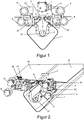
- Fig. 1 shows a section of the device for decorating according to an embodiment of the invention with gap adjustment.
- the already coated products 3 are transported on a grid belt 1.
- a mesh belt 1 another permeable transport medium, for example a plastic belt, can be used.
- a collecting container 2 or collecting trough is attached below the decorating device 7.
- a discharge screw 21 is arranged in the collecting trough 2, which conveys excess decorating material out of the collecting trough 2 so that it can be recirculated and transported to the decorating device 7.
- the discharge screw 21 can also be replaced by other means of transport or an inclination of the collecting trough 2 without additional aids.
- the grating strip 1 is in accordance with FIG Fig. 1 guided around the collecting trough 2 by means of deflecting profiles or rollers.
- a decorating gap 6 is formed below the decorating device 7 between two upper deflecting profiles 4, 5.
- the mesh belt 1 is guided around the collecting trough. Decoration is thus carried out over the gap 6, while any coating composition remaining on the mesh belt 1 is guided around the collecting trough 2 and thus can only drip into the first collecting container, which can be arranged underneath.
- plates can be provided which collect the dripping coating mass from the deflected grating belt 1 and guide it through their inclination into the collecting container of the coating mass. A mixture of both masses is avoided.
- the size of the gap 6 can be adjustable.
- the upper deflection profiles 4 and 5 can be connected to an adjustment unit.
- the first deflection profile 4 here designates the element upstream of the second deflection profile 5 in the production direction.
- the deflection profiles 4, 5 can each be adjusted horizontally. The smaller the products 3 are, the more difficult it becomes to transfer them from a product-feeding belt side to a product-removing belt side. Since the products 3 tilt downwards from the middle of the gap, the gap size 6 can also be changed in the vertical direction.
- a vertical adjustment on the outlet side is more relevant in order - particularly but not only - to prevent the products from tipping over or into the gap 6 for smaller products 3 and thus to be able to better design the transition via the gap 6, as well as the danger to reduce the loss of product 3 due to falling or damage.
- the deflection profiles 4, 5 are adjusted without tilting the deflection profiles, that is to say only by horizontal or vertical displacement. However, tilting of the deflection profiles 4, 5 can also be expedient.
- the horizontal 42, 52 and vertical adjustments 41, 51 ensure a high degree of flexibility and the possibility of adapting the gap size 6 during operation.
- the horizontal gap size 6 should be chosen as large as possible. However, this increases the risk of products 3 being damaged at the gap 6 or falling into the trough 2. To prevent this, on the other hand, the gap size 6 should be as small as possible. A vertical offset should also be set for smaller products 3 so that a tilting movement of the products and falling into the collecting trough 2 can be avoided. Thus, a trade-off between product safety, i.e. Freedom from damage and avoidance of loss of products 3 on the one hand and the mixing of the coating compositions on the other hand.
- Figure 2 shows a perspective view of the device according to Figure 1 with gap 6 closed.
- the illustration of the decorating device has been shown here 7 waived.
- the product 3 travels over the wire mesh belt 1. This setting can be selected, for example, if no decoration of the product 3 is carried out, or the decorating compound matches the coating compound.
- the mesh belt 1 has a product feed side 18 and a product discharge side 19.
- two separate belts 18, 19 can also be used, each of which is deflected at the deflection rollers 4 and 5 and can be adjusted as described above.
- the position of the collecting trough 2 also remains unchanged.
- the belts 18, 19 can be operated synchronously, for example, by means of a belt drive.
- This structure with two separate conveyor or lattice belts 18, 19 can be applied to all of the embodiments according to the invention as in FIGS Figures 1 to 8 shown applied. This can help reduce wear, as fewer redirection points are needed.
- Figure 3 shows a perspective view of the device with the gap 6 slightly open. This was achieved by actuating the first horizontal adjustment 42 and / or the second horizontal adjustment 52.
- the horizontal adjustment can take place, for example, by deflecting the rotary movement on the wheel of the horizontal adjustment 42, 52 via bevel gears on a threaded spindle which displaces the deflection profile 4, 5.
- other mechanical elements or types of gears or the direct attachment of a motor to a threaded spindle or the like. can be ways to move the deflection profiles 4, 5 to set the gap size 6.
- the decorating device 7 can now as in FIG Figure 1 shown, apply the second flowable mass to the product 3 above the gap 6. The excess mass therefore does not drip into the collecting container of the coating mass, but is collected in the collecting trough 2 and can be recirculated. Mixing of the two masses is thereby avoided.
- Figure 4 shows a perspective view of the device in comparison to Figure 3 slightly wider gap 6. Here too, only a horizontal displacement of the deflection profiles 4, 5 was carried out.
- Figure 5 shows a perspective view of the device, wherein on the outlet side in addition to the horizontal displacement of both deflection profiles 4, 5, the second deflection profile 5, ie on the outlet side, has been displaced vertically downward.
- This can when driving over the Gap 6 a tilting movement of the product 3, for example due to adhesion to the mesh belt 1, are intercepted.
- the vertical offset of the deflection profiles 4, 5 from one another can be controlled, for example, by means of a threaded spindle, which is connected to the setting wheel via a worm gear.
- electric or servo motors can also be used here or other types of gear can be useful.
- Figure 6 is a schematic side view of the device with the gap closed. For reasons of clarity, the decorating device 7 is not shown.
- Figure 7 is a schematic side view of the device with the gap open. Here, too, the decorating device 7 attached above the gap 6 is not shown.
- Figure 8 shows a schematic view of an apparatus and the method for covering and decorating according to an embodiment of the invention.
- the products 3 are transported on the grid belt 1 and are first covered by the coating device 8 with a first flowable mass.
- the mesh belt 1 is guided around the collecting trough 2 for the decorating compound below the decorating device 7, so that a gap 6 is formed and the excess coating compound does not drip into the collecting trough 2 and mixes with the decorative compound there.
- the coated products 3 pass over the gap 6 and are covered there by the decorating device 7 with the second flowable mass, the decorating mass.
- the excess decorating compound drips below the gap 6 into the collecting trough 2 and can be recirculated and thus used for the next decorating processes.
- both conveyor belts can be connected, for example, to a belt drive.
- the production line can also be adapted to different products or product sizes without having to stop the machine.
- the horizontal adjustability ensures that the decorating compound does not get on the conveyor belt and mixes with the coating compound, while the vertical adjustability allows small products to be transported over the gap without damage or loss.
- the invention can be used for all production lines with mesh belt or a similar transport medium and two or more units for coating the products "wet on wet".
Abstract
Die Erfindung betrifft eine Vorrichtung und ein Verfahren zum Dekorieren von mit einer ersten fließfähigen Masse überzogenen Produkten mit mindestens einer zweiten fließfähigen Masse, ohne dass sich die beiden fließfähigen Massen miteinander vermengen. Die Vorrichtung weist ein Transportband zum Transport der Produkte, eine Einheit zum Verteilen der zweiten fließfähigen Masse auf den Produkten und einen Auffangbehälter für die zweite fließfähige Masse, der unterhalb der Einheit zum Verteilen der zweiten fließfähigen Masse angeordnet ist, auf. Das Transportband wird mittels mehrerer Umlenkeinrichtungen im Bereich des Auffangbehälters geführt und kann insbesondere um den Auffangbehälter herum gelenkt werden, wobei zwischen zwei oberen Umlenkeinrichtungen der mehreren Umlenkeinrichtungen des Transportbands ein verstellbarer Spalt ausgebildet ist.The invention relates to a device and a method for decorating products coated with a first flowable mass with at least one second flowable mass without the two flowable masses mixing together. The device has a conveyor belt for transporting the products, a unit for distributing the second flowable mass onto the products and a collecting container for the second flowable mass, which is arranged below the unit for distributing the second flowable mass. The conveyor belt is guided in the area of the collecting container by means of several deflecting devices and can in particular be guided around the collecting container, an adjustable gap being formed between two upper deflecting devices of the plurality of deflecting devices of the transport belt.
Description
Die Erfindung betrifft eine Vorrichtung und ein Verfahren zum Dekorieren eines mit einer ersten fließfähigen Masse überzogenen Produkts mit einer zweiten fließfähigen Masse, insbesondere zum Vermeiden einer Vermischung der Massen miteinander in einem Auffangtrog.The invention relates to a device and a method for decorating a product coated with a first flowable mass with a second flowable mass, in particular for avoiding mixing of the masses with one another in a collecting trough.
Eine Vorrichtung zum Überziehen von Produkten, insbesondere Lebensmittelprodukten, mit einer fließfähigen Überzugsmasse ist beispielsweise aus der
Bei der Produktion von Pralinen, Süßwaren, Gebäck o.ä. wird oftmals zusätzlich zu einer Überzugsmasse eine Dekoriermasse aufgebracht. Die Produkte werden dabei auf einem Transportband, beispielsweise einem durchlässigen Gitterband, transportiert und zunächst mit der Überzugsmasse und im Folgenden mit der Dekoriermasse überzogen. Überzug und Dekoriermasse können bspw. Schokolade sein. Dies kann "nass in nass", d.h. vor dem vollständigen Trocknen der Überzugsmasse, geschehen. Überschüssige Masse sowohl der Überzugs-, als auch der Dekoriermasse werden unterhalb des Gitterbands in einem Trog aufgefangen und rezirkuliert. Besonders bei unterschiedlichen Farben der Massen kommt es im Laufe der Produktion zur Kontamination und Verfärbung der Überzugsmasse, da sich diese im Trog bzw. Auffangbehälter mit der Dekoriermasse mischt. Falls ein separater Trog für die Dekoriermasse vorgesehen ist, kommt es dort zur Vermischung der Dekoriermasse mit herabtropfender Überzugsmasse. Dies zieht die Notwendigkeit des vollständigen Austauschs der Masse und Reinigung der Maschine nach sich. Dieser Vorgang verursacht hohe Kosten und ist zeitaufwendig.In the production of chocolates, sweets, pastries or similar a decorating compound is often applied in addition to a coating compound. The products are transported on a conveyor belt, for example a permeable grid belt, and are first coated with the coating compound and then with the decorative compound. The coating and decorative mass can be chocolate, for example. This can be "wet on wet", i.e. before the coating composition has completely dried. Excess mass of both the coating and decorative mass are collected in a trough below the mesh belt and recirculated. In the case of different colors of the materials in particular, the coating material becomes contaminated and discolored in the course of production, since this mixes with the decorating material in the trough or collecting container. If a separate trough is provided for the decorating compound, there is mixing of the decorative compound with dripping coating compound. This necessitates the complete replacement of the mass and cleaning of the machine. This process involves high costs and is time-consuming.
Somit besteht die Aufgabe der Erfindung darin, eine Vorrichtung bereitzustellen, die es ermöglicht, die überschüssige und abgetropfte Dekoriermasse getrennt von der Überzugsmasse aufzufangen, um eine Kontamination und Vermischung der Massen zu verhindern.The object of the invention is therefore to provide a device which makes it possible to collect the excess and drained decorating composition separately from the coating composition in order to prevent contamination and mixing of the compositions.
Die Erfindung betrifft eine Vorrichtung zur Herstellung von Lebensmittelprodukten, insbesondere von Süßwaren, Gebäck oder Pralinen, und insbesondere eine Vorrichtung zum Überziehen von Produkten mit mindestens zwei fließfähigen Massen. Hierfür wird gemäß einer Ausführungsform der Erfindung ein bereits mit einer ersten fließfähigen Masse überzogenes Produkt auf einem Transportband transportiert und mittels einer (Dekorier-) Einheit zum Verteilen einer zweiten fließfähigen Masse, einer Dekoriermasse oder Dekormasse, die zweite fließfähige Masse auf das Produkt aufgebracht. Als Transportband kann insbesondere ein Gitterband zum Einsatz kommen. Das Produkt kann mittels einer in Produktionsrichtung vorher angeordneten weiteren Einheit zum Verteilen der ersten fließfähigen Masse, auch Überzugsmasse genannt, überzogen werden, bevor auf das bereits überzogene Produkt mittels der Dekoriereinheit die zweite fließfähige Masse aufgetragen wird. Die fließfähigen Massen sind beispielhaft fetthaltige Massen, es können allerdings auch andere Massen für Überzug und Dekor verwendet werden. Unterhalb der Dekoriereinheit ist ein Auffangbehälter oder ein Trog angebracht, um die überschüssige Dekoriermasse aufzufangen. Zur Führung des Transportbands sind mehrere Umlenkeinrichtungen vorgesehen. Durch zwei obere Umlenkeinrichtungen wird das Transportband im Bereich der Dekoriereinheit derart umgelenkt, dass ein Spalt zwischen diesen zwei oberen Umlenkpunkten des Transportbands oberhalb des zweiten Trogs für die Dekoriermasse ausgebildet wird. Hierfür kann das Transportband insbesondere mit Hilfe der Umlenkeinrichtungen um den Trog herumgeführt werden, wobei durch zwei der Umlenkeinrichtungen, nämlich den oberen Umlenkeinrichtungen, die sich auf einer Höhe zwischen der Dekoriereinheit und dem Trog befinden, der Spalt gebildet wird. Durch weitere Umlenkeinrichtungen kann das Transportband dann derart um den Trog herum geführt werden, so dass der Weg des Transportbands unterhalb des Trogs verläuft und überschüssige Überzugs- und/oder Dekoriermasse, die sich auf dem Transportband befindet, nicht in den Trog tropfen kann. Alternativ können auch zwei getrennte Tranksportbänder zum Einsatz kommen, zwischen denen der Spalt zwischen oberen Umlenkeinrichtunen ausgebildet ist, die in diesem Fall jeweils die Laufrichtung der Transportbänder umkehren. Um bei dieser Alternative einen Synchronlauf zu gewährleisten, können beide Transportbänder beispielsweise mit einem Riemenantrieb verbunden sein.The invention relates to a device for producing food products, in particular sweets, pastries or chocolates, and in particular to a device for coating products with at least two flowable masses. For this purpose, according to one embodiment of the invention, a product already coated with a first flowable mass is transported on a conveyor belt and the second flowable mass is applied to the product by means of a (decorating) unit for distributing a second flowable mass, a decorating mass or decorative mass. A grid belt can in particular be used as the conveyor belt. The product can be coated by means of a further unit for distributing the first flowable mass, also called coating mass, arranged beforehand in the direction of production, before the second flowable mass is applied to the already coated product by means of the decorating unit. The flowable masses are examples of fatty masses, but other masses can also be used for coating and decor. A collecting container or a trough is attached below the decorating unit in order to collect the excess decorating compound. Several deflection devices are provided for guiding the conveyor belt. The conveyor belt in the region of the decorating unit is deflected by two upper deflecting devices such that a gap is formed between these two upper deflecting points of the conveyor belt above the second trough for the decorating compound. For this purpose, the conveyor belt can be guided around the trough in particular with the aid of the deflection devices, the gap being formed by two of the deflection devices, namely the upper deflection devices, which are located at a height between the decorating unit and the trough. By means of further deflection devices, the conveyor belt can then be guided around the trough in such a way that the path of the conveyor belt runs below the trough and excess coating and / or decorative mass which is located on the conveyor belt cannot drip into the trough. Alternatively, two separate conveyor belts can also be used, between which the gap is formed between upper deflection devices, which in this case in each case reverse the running direction of the conveyor belts. In order to ensure synchronous running in this alternative, both conveyor belts can be connected, for example, to a belt drive.
Die Spaltgröße ist dabei einstellbar. Dadurch, dass die Dekoriermasse über dem Spalt auf dem Produkt verteilt wird, tropft die überschüssige Dekoriermasse in den Trog und gelangt nicht auf das Transportband. Somit vermischt sich die Dekoriermasse nicht mit der Überzugsmasse. Weiterhin kann unterhalb des Transportbands, insbesondere in dem Bereich, in dem das Produkt mit der Überzugsmasse überzogen wird, also stromaufwärts der Dekoriereinheit, ein Auffangbehälter für überschüssige Überzugsmasse angebracht sein, in dem die herabtropfende Überzugsmasse gesammelt und rezirkuliert wird.The gap size is adjustable. Because the decorating compound is distributed over the gap on the product, the excess decorating compound drips into the trough and does not get there on the conveyor belt. Thus the decorating compound does not mix with the coating compound. Furthermore, below the conveyor belt, in particular in the area in which the product is coated with the coating composition, i.e. upstream of the decorating unit, a collecting container for excess coating composition can be attached, in which the dripping coating composition is collected and recirculated.
Insbesondere ist die Erfindung auf eine Vorrichtung und ein Verfahren zum Dekorieren von mit einer ersten fließfähigen Masse überzogenen Produkten mit mindestens einer zweiten fließfähigen Masse gerichtet. Die Vorrichtung kann insbesondere in einer Überziehmaschine angeordnet sein. Die Vorrichtung weist ein Transportband zum Transport der Produkte, eine Einheit zum Verteilen der zweiten fließfähigen Masse auf den Produkten und einen Auffangbehälter für die zweite fließfähige Masse, der unterhalb der Einheit zum Verteilen der zweiten fließfähigen Masse angeordnet ist, auf. Das Transportband wird mittels mehrerer Umlenkeinrichtungen, also insbesondere Umlenkprofilen bzw. Umlenkrollen, im Bereich des Auffangbehälters geführt und kann um den Auffangbehälter herum gelenkt werden. Zwischen zwei oberen Umlenkeinrichtungen der mehreren Umlenkeinrichungen des Transportbands wird ein verstellbarer Spalt ausgebildet. Die abhängigen Ansprüche beschreiben Ausführungsformen der Erfindung.In particular, the invention is directed to an apparatus and a method for decorating products coated with a first flowable mass with at least a second flowable mass. The device can in particular be arranged in a coating machine. The device has a conveyor belt for transporting the products, a unit for distributing the second flowable mass onto the products and a collecting container for the second flowable mass, which is arranged below the unit for distributing the second flowable mass. The conveyor belt is guided in the area of the collecting container by means of several deflecting devices, that is to say in particular deflecting profiles or deflecting rollers, and can be guided around the collecting container. An adjustable gap is formed between two upper deflection devices of the plurality of deflection devices of the conveyor belt. The dependent claims describe embodiments of the invention.
Die vorliegende Erfindung wird anhand der Zeichnungen verdeutlicht. Es zeigen:
-
Fig. 1 eine Seitenansicht der Vorrichtung zum Dekorieren gemäß einer Ausführungsform der Erfindung, -
Fig. 2 eine Perspektivansicht der Vorrichtung gemäßFig. 1 mit optionaler Spalteinstellung, -
Fig. 3 eine Perspektivansicht der Vorrichtung gemäßFig. 1 mit geöffnetem Spalt, -
Fig. 4 eine Perspektivansicht der Vorrichtung gemäßFig. 1 mit geöffnetem Spalt, -
Fig. 5 eine Perspektivansicht der Vorrichtung gemäßFig. 1 mit geöffnetem Spalt, -
Fig. 6 eine schematische Seitenansicht der Vorrichtung gemäßFig. 1 , -
Fig. 7 eine schematische Seitenansicht der Vorrichtung gemäßFig. 1 und -
Fig. 8 eine schematische Ansicht einer Vorrichtung zum Überziehen und Dekorieren von Lebensmittelprodukten.
-
Fig. 1 2 shows a side view of the device for decorating according to an embodiment of the invention, -
Fig. 2 a perspective view of the device according toFig. 1 with optional column setting, -
Fig. 3 a perspective view of the device according toFig. 1 with open gap, -
Fig. 4 a perspective view of the device according toFig. 1 with open gap, -
Fig. 5 a perspective view of the device according toFig. 1 with open gap, -
Fig. 6 is a schematic side view of the deviceFig. 1 , -
Fig. 7 is a schematic side view of the deviceFig. 1 and -
Fig. 8 a schematic view of a device for coating and decorating food products.
Im Folgenden bezeichnen gleiche Bezugszeichen, sofern nicht anders spezifiziert, gleiche oder ähnliche Elemente.Unless otherwise specified, the same reference symbols denote the same or similar elements.
Um zu verhindern, dass Überzugsmasse und Dekoriermasse miteinander vermengt werden, wird das Gitterband 1 gemäß
Um die Vorrichtung an verschiedene Produktgrößen anpassen zu können, kann die Größe des Spalts 6 einstellbar sein. Hierfür können die oberen Umlenkprofile 4 und 5 mit einer Einstelleinheit verbunden sein. Das erste Umlenkprofil 4 bezeichnet hier das in Produktionsrichtung dem zweiten Umlenkprofil 5 vorgelagerte Element. Die Umlenkprofile 4, 5 können jeweils horizontal verstellt werden. Je kleiner die Produkte 3 sind, desto schwieriger wird es, sie von einer produktzuführenden Bandseite auf eine produktabführende Bandseite zu übergeben. Da die Produkte 3 ab der Spaltmitte nach unten kippen, kann die Spaltgröße 6 zusätzlich in vertikaler Richtung verändert werden. Dadurch, dass man auslaufseitig das Umlenkprofil 5 tiefer stellt, kann man etwas näher an das einlaufseitige Umlenkprofil 4 herankommen, um ein Abstürzen der Produkte 3 zu verhindern und dennoch mit einem Spalt 6 arbeiten zu können. So können die Produkte 3 sicher von einem produktzuführenden Bandteil auf ein produktabführendes Bandteil weiter transportiert werden. Hierfür sind vertikale Verstellungen 41, 51 und horizontale Verstellungen 42, 52 vorgesehen. Diese können beispielhaft manuell mittels Kreuzgriffen 9 bedient werden. Die manuelle Verstellung kann auch durch eine automatische Verstellung, beispielsweise mit Elektro- oder Servomotoren, ersetzt werden. Die horizontale Verstellbarkeit kann dabei etwa 5-30 mm betragen. Die vertikale Verstellbarkeit kann etwa bis zu 6 mm betragen. Auch andere Bereiche für die Verstellbarkeit können je nach Produktgröße zweckdienlich sein. Dabei ist eine vertikale Verstellung relevanter auf der Auslaufseite, um - besonders, aber nicht nur - für kleinere Produkte 3 ein Kippen der Produkte über bzw. in den Spalt 6 abzufangen und so den Übergang über den Spalt 6 besser gestalten zu können, sowie die Gefahr des Verlusts des Produkts 3 durch Herabfallen oder der Beschädigung zu vermindern.In order to be able to adapt the device to different product sizes, the size of the
Die Verstellung der Umlenkprofile 4, 5 wird ohne ein Verkippen der Umlenkprofile, also lediglich durch horizontale bzw. vertikale Verschiebung, durchgeführt. Es kann allerdings auch ein Verkippen der Umlenkprofile 4, 5 zweckdienlich sein.The deflection profiles 4, 5 are adjusted without tilting the deflection profiles, that is to say only by horizontal or vertical displacement. However, tilting of the deflection profiles 4, 5 can also be expedient.
Durch eine Verstellbarkeit der Spaltgröße 6 kann bei einem Produktwechsel eine schnelle Anpassung erfolgen, ohne dass Fachpersonal bei Stillstand der Maschine Umbauten vornehmen muss. Die horizontalen 42, 52 und vertikalen Verstellungen 41, 51 gewährleisten eine hohe Flexibilität und die Möglichkeit der Anpassung der Spaltgröße 6 im Betrieb.Due to the adjustability of the
Um eine geringe Kontamination der fließfähigen Massen untereinander sicherzustellen, sollte die horizontale Spaltgröße 6 möglichst groß gewählt sein. Dadurch steigt jedoch die Gefahr, dass Produkte 3 an dem Spalt 6 beschädigt werden oder in den Trog 2 fallen. Um dies zu verhindern, sollte andererseits die Spaltgröße 6 möglichst klein sein. Für kleinere Produkte 3 sollte zusätzlich ein vertikaler Versatz eingestellt sein, damit eine Kippbewegung der Produkte und ein Stürzen in den Auffangtrog 2 vermieden werden kann. Somit muss eine Abwägung zwischen Produktsicherheit, d.h. Freiheit von Beschädigungen und Vermeiden eines Verlusts von Produkten 3 auf der einen und der Vermischung der Überzugsmassen auf der anderen Seite getroffen werden.In order to ensure a low contamination of the flowable masses with one another, the
Das Gitterband 1 weist eine produktzuführende Seite 18 und eine produktabführende Seite 19 auf. Anstelle eines umlaufenden Bands 1 können auch zwei getrennte Bänder 18, 19 verwendet werden, die jeweils an den Umlenkrollen 4 bzw. 5 umgelenkt werden und wie oben beschrieben verstellt werden können. Auch die Position des Auffangtrogs 2 bleibt unverändert. Die Bänder 18, 19 können beispielsweise mittels eines Riemenantriebs synchron betrieben werden. Dieser Aufbau mit zwei getrennten Transport- bzw. Gitterbändern 18, 19 kann auf alle erfindungsgemäßen Ausführungsformen wie in den
Anstelle der Umlenkung des Transportbands um den Auffangtrog können auch zwei separate Transportbänder vorgesehen sein, zwischen denen ein Spalt ausgebildet ist. Um einen Synchronlauf zu gewährleisten, können beide Transportbänder beispielsweise mit einem Riemenantrieb verbunden sein.Instead of deflecting the conveyor belt around the collecting trough, two separate conveyor belts can also be provided, between which a gap is formed. To ensure synchronous running, both conveyor belts can be connected, for example, to a belt drive.
Durch die erfindungsgemäß getrennten Auffangbehälter für überschüssige Überzugs- bzw. Dekoriermasse sowie dem Dekorieren über einem Spalt ist es möglich, eine Vermischung von Überzugsmasse und Dekoriermasse effizient zu verhindern. Dadurch ist kein erzwungenes Austauschen der Masse aufgrund von Kontamination durch die jeweils andere Masse notwendig. Somit ist die Produktion ressourcenschonend und die Stillstandszeit der Maschine aufgrund von Reinigung oder Austausch der Dekorier- bzw. Überzugsmasse kann minimiert werden.Due to the collecting container according to the invention for excess coating or decorating mass and decorating over a gap, it is possible to efficiently prevent mixing of the coating mass and decorating mass. This means that there is no need to replace the mass due to contamination from the other mass. This means that production is resource-saving and the downtime of the machine due to cleaning or replacement of the decorating or coating compound can be minimized.
Durch die optionale Spalteinstellung kann die Produktionslinie ferner, ohne die Maschine stoppen zu müssen, an verschiedene Produkte bzw. Produktgrößen angepasst werden. Die horizontale Verstellbarkeit gewährleistet, dass die Dekoriermasse nicht auf das Transportband gerät und sich mit der Überzugsmasse vermischt, während die vertikale Verstellbarkeit es erlaubt, auch kleine Produkte beschädigungs- und verlustfrei über den Spalt zu transportieren.With the optional gap setting, the production line can also be adapted to different products or product sizes without having to stop the machine. The horizontal adjustability ensures that the decorating compound does not get on the conveyor belt and mixes with the coating compound, while the vertical adjustability allows small products to be transported over the gap without damage or loss.
Die Erfindung kann für alle Produktionslinien mit Gitterband oder einem ähnlichen Transportmedium und zwei oder mehr Einheiten zum Überziehen der Produkte "nass in nass" verwendet werden.The invention can be used for all production lines with mesh belt or a similar transport medium and two or more units for coating the products "wet on wet".
- 11
- GitterbandMesh belt
- 1818th
- Produktzuführende BandseiteProduct-feeding hinge side
- 1919th
- Produktabführende BandseiteProduct-removing hinge side
- 22nd
- Zweiter AuffangtrogSecond collecting trough
- 2121
- AustragschneckeDischarge screw
- 33rd
- Produktproduct
- 44th
- Erstes UmlenkprofilFirst deflection profile
- 4141
- Vertikale Verstellung des ersten UmlenkprofilsVertical adjustment of the first deflection profile
- 4242
- Horizontale Verstellung des ersten UmlenkprofilsHorizontal adjustment of the first deflection profile
- 55
- Zweites UmlenkprofilSecond deflection profile
- 5151
- Vertikale Verstellung des zweiten UmlenkprofilsVertical adjustment of the second deflection profile
- 5252
- Horizontale Verstellung des zweiten UmlenkprofilsHorizontal adjustment of the second deflection profile
- 66
- Spaltgap
- 77
- DekoriervorrichtungDecorating device
- 88th
- ÜberzugsvorrichtungCoating device
- 99
- KreuzgriffCross handle
- 11, 12, 1311, 12, 13
- UmlenkrollenPulleys
Claims (10)
wobei ein Bereich der vertikalen Verschiebung 6 mm beträgt.Device according to one of the preceding claims, wherein a range of horizontal displacement is 5 to 30 mm and / or
a range of vertical displacement is 6 mm.
Applications Claiming Priority (1)
| Application Number | Priority Date | Filing Date | Title |
|---|---|---|---|
| DE102018215652.2A DE102018215652A1 (en) | 2018-09-14 | 2018-09-14 | Decorating gap |
Publications (2)
| Publication Number | Publication Date |
|---|---|
| EP3628167A1 true EP3628167A1 (en) | 2020-04-01 |
| EP3628167B1 EP3628167B1 (en) | 2022-10-26 |
Family
ID=67928673
Family Applications (1)
| Application Number | Title | Priority Date | Filing Date |
|---|---|---|---|
| EP19196638.1A Active EP3628167B1 (en) | 2018-09-14 | 2019-09-11 | Coating apparatus with gap |
Country Status (3)
| Country | Link |
|---|---|
| EP (1) | EP3628167B1 (en) |
| DE (1) | DE102018215652A1 (en) |
| DK (1) | DK3628167T3 (en) |
Citations (5)
| Publication number | Priority date | Publication date | Assignee | Title |
|---|---|---|---|---|
| BE334586A (en) * | ||||
| EP0632962A1 (en) * | 1993-07-06 | 1995-01-11 | SOLLICH GmbH & Co. KG | Apparatus to remove the coating deposited on the back bottom of products in portions |
| EP1498037A1 (en) * | 2003-07-18 | 2005-01-19 | Sollich KG | Method and device for single-sided coating of confectionery with coating mass |
| EP1582100A1 (en) * | 2004-04-02 | 2005-10-05 | CFS Bakel B.V. | Installation for coating food products with a fluid substance |
| DE102013001743A1 (en) | 2013-01-25 | 2014-07-31 | Hosokawa Bepex Gmbh | Device, useful for coating food products with e.g. chocolate and sugar, comprises inlet end and outlet end, and driven grid-like endless conveyor belt on which products are arranged and conveyed from inlet end to outlet end |
Family Cites Families (1)
| Publication number | Priority date | Publication date | Assignee | Title |
|---|---|---|---|---|
| GB0206540D0 (en) * | 2002-03-20 | 2002-05-01 | Apv Systems Ltd | Coating of food products |
-
2018
- 2018-09-14 DE DE102018215652.2A patent/DE102018215652A1/en active Pending
-
2019
- 2019-09-11 EP EP19196638.1A patent/EP3628167B1/en active Active
- 2019-09-11 DK DK19196638.1T patent/DK3628167T3/en active
Patent Citations (5)
| Publication number | Priority date | Publication date | Assignee | Title |
|---|---|---|---|---|
| BE334586A (en) * | ||||
| EP0632962A1 (en) * | 1993-07-06 | 1995-01-11 | SOLLICH GmbH & Co. KG | Apparatus to remove the coating deposited on the back bottom of products in portions |
| EP1498037A1 (en) * | 2003-07-18 | 2005-01-19 | Sollich KG | Method and device for single-sided coating of confectionery with coating mass |
| EP1582100A1 (en) * | 2004-04-02 | 2005-10-05 | CFS Bakel B.V. | Installation for coating food products with a fluid substance |
| DE102013001743A1 (en) | 2013-01-25 | 2014-07-31 | Hosokawa Bepex Gmbh | Device, useful for coating food products with e.g. chocolate and sugar, comprises inlet end and outlet end, and driven grid-like endless conveyor belt on which products are arranged and conveyed from inlet end to outlet end |
Also Published As
| Publication number | Publication date |
|---|---|
| DK3628167T3 (en) | 2022-12-05 |
| EP3628167B1 (en) | 2022-10-26 |
| DE102018215652A1 (en) | 2020-03-19 |
Similar Documents
| Publication | Publication Date | Title |
|---|---|---|
| EP0603781A2 (en) | Coatingmachine for processing chocolate and similar masses | |
| DE3716666A1 (en) | Panel-dividing installation with a ripsaw and a cross-cut saw | |
| DE2219040A1 (en) | Plastic powder spray cabin - with excess powder on spray space floor moved to suction opening | |
| DE1556704C3 (en) | ||
| DE941384C (en) | Method and device for the production of fibers from fiber-forming materials | |
| EP3628167B1 (en) | Coating apparatus with gap | |
| EP3025834B1 (en) | Guiding device | |
| DE4131107C2 (en) | Device for cutting continuously fed strip material | |
| DE4215857C2 (en) | Plant for spreading pressed material mats in the course of the production of chipboard | |
| DE10134602B4 (en) | Belt conveyor for general cargo | |
| DE19920071A1 (en) | Device for covering goods, in particular confectionery pieces, with a flowable coating mass | |
| EP4214010A1 (en) | Method and spraying apparatus for thermal surface treatment of a metal product | |
| DE3425165C2 (en) | ||
| DE2136053B2 (en) | Machine for making layered biscuits | |
| EP3341297B1 (en) | Shrinking tunnel | |
| DE60307855T2 (en) | MANUFACTURING ROUTE FOR BREADFORMS | |
| DE3420206A1 (en) | DEVICE FOR COVERING CONFECTIONERY ITEMS | |
| DD211938A5 (en) | METHOD AND DEVICE FOR DRYING CERAMIC FORMULAS | |
| DE505739C (en) | Device on chocolate enrobing machines for regulating the base coating thickness | |
| DE102007062468B3 (en) | Covering machine for sweets with a bottom wall station | |
| EP4133941A1 (en) | Dough strip conveyor with a device for feeding a pasty food product | |
| DE19633656C1 (en) | Liquid artificial resin applicator for flexible support mat material | |
| DE10211215A1 (en) | Powder painting plant for painting both sides of sheet cutouts has last processing point including conveyors and two endless belts with parallel ends | |
| DE4316218A1 (en) | Method and device for reducing flour dust in combined dough dividing and circular knitting machines | |
| DE3603668C2 (en) | Device for milling building blocks |
Legal Events
| Date | Code | Title | Description |
|---|---|---|---|
| PUAI | Public reference made under article 153(3) epc to a published international application that has entered the european phase |
Free format text: ORIGINAL CODE: 0009012 |
|
| STAA | Information on the status of an ep patent application or granted ep patent |
Free format text: STATUS: REQUEST FOR EXAMINATION WAS MADE |
|
| 17P | Request for examination filed |
Effective date: 20191011 |
|
| AK | Designated contracting states |
Kind code of ref document: A1 Designated state(s): AL AT BE BG CH CY CZ DE DK EE ES FI FR GB GR HR HU IE IS IT LI LT LU LV MC MK MT NL NO PL PT RO RS SE SI SK SM TR |
|
| AX | Request for extension of the european patent |
Extension state: BA ME |
|
| RBV | Designated contracting states (corrected) |
Designated state(s): AL AT BE BG CH CY CZ DE DK EE ES FI FR GB GR HR HU IE IS IT LI LT LU LV MC MK MT NL NO PL PT RO RS SE SI SK SM TR |
|
| GRAP | Despatch of communication of intention to grant a patent |
Free format text: ORIGINAL CODE: EPIDOSNIGR1 |
|
| STAA | Information on the status of an ep patent application or granted ep patent |
Free format text: STATUS: GRANT OF PATENT IS INTENDED |
|
| INTG | Intention to grant announced |
Effective date: 20220512 |
|
| GRAS | Grant fee paid |
Free format text: ORIGINAL CODE: EPIDOSNIGR3 |
|
| GRAA | (expected) grant |
Free format text: ORIGINAL CODE: 0009210 |
|
| STAA | Information on the status of an ep patent application or granted ep patent |
Free format text: STATUS: THE PATENT HAS BEEN GRANTED |
|
| AK | Designated contracting states |
Kind code of ref document: B1 Designated state(s): AL AT BE BG CH CY CZ DE DK EE ES FI FR GB GR HR HU IE IS IT LI LT LU LV MC MK MT NL NO PL PT RO RS SE SI SK SM TR |
|
| REG | Reference to a national code |
Ref country code: GB Ref legal event code: FG4D Free format text: NOT ENGLISH |
|
| REG | Reference to a national code |
Ref country code: CH Ref legal event code: EP |
|
| REG | Reference to a national code |
Ref country code: AT Ref legal event code: REF Ref document number: 1526403 Country of ref document: AT Kind code of ref document: T Effective date: 20221115 |
|
| REG | Reference to a national code |
Ref country code: DE Ref legal event code: R096 Ref document number: 502019006022 Country of ref document: DE |
|
| REG | Reference to a national code |
Ref country code: IE Ref legal event code: FG4D Free format text: LANGUAGE OF EP DOCUMENT: GERMAN |
|
| REG | Reference to a national code |
Ref country code: DK Ref legal event code: T3 Effective date: 20221130 |
|
| REG | Reference to a national code |
Ref country code: SK Ref legal event code: T3 Ref document number: E 40946 Country of ref document: SK |
|
| REG | Reference to a national code |
Ref country code: LT Ref legal event code: MG9D |
|
| REG | Reference to a national code |
Ref country code: NL Ref legal event code: MP Effective date: 20221026 |
|
| PG25 | Lapsed in a contracting state [announced via postgrant information from national office to epo] |
Ref country code: NL Free format text: LAPSE BECAUSE OF FAILURE TO SUBMIT A TRANSLATION OF THE DESCRIPTION OR TO PAY THE FEE WITHIN THE PRESCRIBED TIME-LIMIT Effective date: 20221026 |
|
| PG25 | Lapsed in a contracting state [announced via postgrant information from national office to epo] |
Ref country code: SE Free format text: LAPSE BECAUSE OF FAILURE TO SUBMIT A TRANSLATION OF THE DESCRIPTION OR TO PAY THE FEE WITHIN THE PRESCRIBED TIME-LIMIT Effective date: 20221026 Ref country code: PT Free format text: LAPSE BECAUSE OF FAILURE TO SUBMIT A TRANSLATION OF THE DESCRIPTION OR TO PAY THE FEE WITHIN THE PRESCRIBED TIME-LIMIT Effective date: 20230227 Ref country code: NO Free format text: LAPSE BECAUSE OF FAILURE TO SUBMIT A TRANSLATION OF THE DESCRIPTION OR TO PAY THE FEE WITHIN THE PRESCRIBED TIME-LIMIT Effective date: 20230126 Ref country code: LT Free format text: LAPSE BECAUSE OF FAILURE TO SUBMIT A TRANSLATION OF THE DESCRIPTION OR TO PAY THE FEE WITHIN THE PRESCRIBED TIME-LIMIT Effective date: 20221026 Ref country code: FI Free format text: LAPSE BECAUSE OF FAILURE TO SUBMIT A TRANSLATION OF THE DESCRIPTION OR TO PAY THE FEE WITHIN THE PRESCRIBED TIME-LIMIT Effective date: 20221026 Ref country code: ES Free format text: LAPSE BECAUSE OF FAILURE TO SUBMIT A TRANSLATION OF THE DESCRIPTION OR TO PAY THE FEE WITHIN THE PRESCRIBED TIME-LIMIT Effective date: 20221026 |
|
| PG25 | Lapsed in a contracting state [announced via postgrant information from national office to epo] |
Ref country code: RS Free format text: LAPSE BECAUSE OF FAILURE TO SUBMIT A TRANSLATION OF THE DESCRIPTION OR TO PAY THE FEE WITHIN THE PRESCRIBED TIME-LIMIT Effective date: 20221026 Ref country code: PL Free format text: LAPSE BECAUSE OF FAILURE TO SUBMIT A TRANSLATION OF THE DESCRIPTION OR TO PAY THE FEE WITHIN THE PRESCRIBED TIME-LIMIT Effective date: 20221026 Ref country code: LV Free format text: LAPSE BECAUSE OF FAILURE TO SUBMIT A TRANSLATION OF THE DESCRIPTION OR TO PAY THE FEE WITHIN THE PRESCRIBED TIME-LIMIT Effective date: 20221026 Ref country code: IS Free format text: LAPSE BECAUSE OF FAILURE TO SUBMIT A TRANSLATION OF THE DESCRIPTION OR TO PAY THE FEE WITHIN THE PRESCRIBED TIME-LIMIT Effective date: 20230226 Ref country code: HR Free format text: LAPSE BECAUSE OF FAILURE TO SUBMIT A TRANSLATION OF THE DESCRIPTION OR TO PAY THE FEE WITHIN THE PRESCRIBED TIME-LIMIT Effective date: 20221026 Ref country code: GR Free format text: LAPSE BECAUSE OF FAILURE TO SUBMIT A TRANSLATION OF THE DESCRIPTION OR TO PAY THE FEE WITHIN THE PRESCRIBED TIME-LIMIT Effective date: 20230127 |
|
| P01 | Opt-out of the competence of the unified patent court (upc) registered |
Effective date: 20230523 |
|
| REG | Reference to a national code |
Ref country code: DE Ref legal event code: R097 Ref document number: 502019006022 Country of ref document: DE |
|
| PG25 | Lapsed in a contracting state [announced via postgrant information from national office to epo] |
Ref country code: SM Free format text: LAPSE BECAUSE OF FAILURE TO SUBMIT A TRANSLATION OF THE DESCRIPTION OR TO PAY THE FEE WITHIN THE PRESCRIBED TIME-LIMIT Effective date: 20221026 Ref country code: RO Free format text: LAPSE BECAUSE OF FAILURE TO SUBMIT A TRANSLATION OF THE DESCRIPTION OR TO PAY THE FEE WITHIN THE PRESCRIBED TIME-LIMIT Effective date: 20221026 Ref country code: EE Free format text: LAPSE BECAUSE OF FAILURE TO SUBMIT A TRANSLATION OF THE DESCRIPTION OR TO PAY THE FEE WITHIN THE PRESCRIBED TIME-LIMIT Effective date: 20221026 Ref country code: CZ Free format text: LAPSE BECAUSE OF FAILURE TO SUBMIT A TRANSLATION OF THE DESCRIPTION OR TO PAY THE FEE WITHIN THE PRESCRIBED TIME-LIMIT Effective date: 20221026 |
|
| PG25 | Lapsed in a contracting state [announced via postgrant information from national office to epo] |
Ref country code: AL Free format text: LAPSE BECAUSE OF FAILURE TO SUBMIT A TRANSLATION OF THE DESCRIPTION OR TO PAY THE FEE WITHIN THE PRESCRIBED TIME-LIMIT Effective date: 20221026 |
|
| PLBE | No opposition filed within time limit |
Free format text: ORIGINAL CODE: 0009261 |
|
| STAA | Information on the status of an ep patent application or granted ep patent |
Free format text: STATUS: NO OPPOSITION FILED WITHIN TIME LIMIT |
|
| 26N | No opposition filed |
Effective date: 20230727 |
|
| PGFP | Annual fee paid to national office [announced via postgrant information from national office to epo] |
Ref country code: TR Payment date: 20230905 Year of fee payment: 5 |
|
| PG25 | Lapsed in a contracting state [announced via postgrant information from national office to epo] |
Ref country code: SI Free format text: LAPSE BECAUSE OF FAILURE TO SUBMIT A TRANSLATION OF THE DESCRIPTION OR TO PAY THE FEE WITHIN THE PRESCRIBED TIME-LIMIT Effective date: 20221026 |
|
| PGFP | Annual fee paid to national office [announced via postgrant information from national office to epo] |
Ref country code: SK Payment date: 20230905 Year of fee payment: 5 Ref country code: DK Payment date: 20230921 Year of fee payment: 5 Ref country code: DE Payment date: 20230919 Year of fee payment: 5 |
|
| REG | Reference to a national code |
Ref country code: CH Ref legal event code: PL |