EP3628015B1 - Stilett und intubationskit - Google Patents
Stilett und intubationskit Download PDFInfo
- Publication number
- EP3628015B1 EP3628015B1 EP18721384.8A EP18721384A EP3628015B1 EP 3628015 B1 EP3628015 B1 EP 3628015B1 EP 18721384 A EP18721384 A EP 18721384A EP 3628015 B1 EP3628015 B1 EP 3628015B1
- Authority
- EP
- European Patent Office
- Prior art keywords
- stylet
- tube
- tip
- actuator
- pivotable
- Prior art date
- Legal status (The legal status is an assumption and is not a legal conclusion. Google has not performed a legal analysis and makes no representation as to the accuracy of the status listed.)
- Active
Links
Images


Classifications
-
- A—HUMAN NECESSITIES
- A61—MEDICAL OR VETERINARY SCIENCE; HYGIENE
- A61B—DIAGNOSIS; SURGERY; IDENTIFICATION
- A61B1/00—Instruments for performing medical examinations of the interior of cavities or tubes of the body by visual or photographical inspection, e.g. endoscopes; Illuminating arrangements therefor
- A61B1/005—Flexible endoscopes
- A61B1/0051—Flexible endoscopes with controlled bending of insertion part
- A61B1/0052—Constructional details of control elements, e.g. handles
-
- A—HUMAN NECESSITIES
- A61—MEDICAL OR VETERINARY SCIENCE; HYGIENE
- A61B—DIAGNOSIS; SURGERY; IDENTIFICATION
- A61B1/00—Instruments for performing medical examinations of the interior of cavities or tubes of the body by visual or photographical inspection, e.g. endoscopes; Illuminating arrangements therefor
- A61B1/005—Flexible endoscopes
- A61B1/008—Articulations
-
- A—HUMAN NECESSITIES
- A61—MEDICAL OR VETERINARY SCIENCE; HYGIENE
- A61B—DIAGNOSIS; SURGERY; IDENTIFICATION
- A61B1/00—Instruments for performing medical examinations of the interior of cavities or tubes of the body by visual or photographical inspection, e.g. endoscopes; Illuminating arrangements therefor
- A61B1/04—Instruments for performing medical examinations of the interior of cavities or tubes of the body by visual or photographical inspection, e.g. endoscopes; Illuminating arrangements therefor combined with photographic or television appliances
- A61B1/05—Instruments for performing medical examinations of the interior of cavities or tubes of the body by visual or photographical inspection, e.g. endoscopes; Illuminating arrangements therefor combined with photographic or television appliances characterised by the image sensor, e.g. camera, being in the distal end portion
-
- A—HUMAN NECESSITIES
- A61—MEDICAL OR VETERINARY SCIENCE; HYGIENE
- A61M—DEVICES FOR INTRODUCING MEDIA INTO, OR ONTO, THE BODY; DEVICES FOR TRANSDUCING BODY MEDIA OR FOR TAKING MEDIA FROM THE BODY; DEVICES FOR PRODUCING OR ENDING SLEEP OR STUPOR
- A61M16/00—Devices for influencing the respiratory system of patients by gas treatment, e.g. ventilators; Tracheal tubes
- A61M16/04—Tracheal tubes
- A61M16/0402—Special features for tracheal tubes not otherwise provided for
- A61M16/0418—Special features for tracheal tubes not otherwise provided for with integrated means for changing the degree of curvature, e.g. for easy intubation
-
- A—HUMAN NECESSITIES
- A61—MEDICAL OR VETERINARY SCIENCE; HYGIENE
- A61M—DEVICES FOR INTRODUCING MEDIA INTO, OR ONTO, THE BODY; DEVICES FOR TRANSDUCING BODY MEDIA OR FOR TAKING MEDIA FROM THE BODY; DEVICES FOR PRODUCING OR ENDING SLEEP OR STUPOR
- A61M16/00—Devices for influencing the respiratory system of patients by gas treatment, e.g. ventilators; Tracheal tubes
- A61M16/04—Tracheal tubes
- A61M16/0434—Cuffs
- A61M16/045—Cuffs with cuffs partially or completely inflated by the respiratory gas
-
- A—HUMAN NECESSITIES
- A61—MEDICAL OR VETERINARY SCIENCE; HYGIENE
- A61M—DEVICES FOR INTRODUCING MEDIA INTO, OR ONTO, THE BODY; DEVICES FOR TRANSDUCING BODY MEDIA OR FOR TAKING MEDIA FROM THE BODY; DEVICES FOR PRODUCING OR ENDING SLEEP OR STUPOR
- A61M16/00—Devices for influencing the respiratory system of patients by gas treatment, e.g. ventilators; Tracheal tubes
- A61M16/04—Tracheal tubes
- A61M16/0463—Tracheal tubes combined with suction tubes, catheters or the like; Outside connections
-
- A—HUMAN NECESSITIES
- A61—MEDICAL OR VETERINARY SCIENCE; HYGIENE
- A61M—DEVICES FOR INTRODUCING MEDIA INTO, OR ONTO, THE BODY; DEVICES FOR TRANSDUCING BODY MEDIA OR FOR TAKING MEDIA FROM THE BODY; DEVICES FOR PRODUCING OR ENDING SLEEP OR STUPOR
- A61M16/00—Devices for influencing the respiratory system of patients by gas treatment, e.g. ventilators; Tracheal tubes
- A61M16/04—Tracheal tubes
- A61M16/0488—Mouthpieces; Means for guiding, securing or introducing the tubes
-
- A—HUMAN NECESSITIES
- A61—MEDICAL OR VETERINARY SCIENCE; HYGIENE
- A61M—DEVICES FOR INTRODUCING MEDIA INTO, OR ONTO, THE BODY; DEVICES FOR TRANSDUCING BODY MEDIA OR FOR TAKING MEDIA FROM THE BODY; DEVICES FOR PRODUCING OR ENDING SLEEP OR STUPOR
- A61M16/00—Devices for influencing the respiratory system of patients by gas treatment, e.g. ventilators; Tracheal tubes
- A61M16/06—Respiratory or anaesthetic masks
- A61M16/0666—Nasal cannulas or tubing
- A61M16/0672—Nasal cannula assemblies for oxygen therapy
-
- A—HUMAN NECESSITIES
- A61—MEDICAL OR VETERINARY SCIENCE; HYGIENE
- A61B—DIAGNOSIS; SURGERY; IDENTIFICATION
- A61B1/00—Instruments for performing medical examinations of the interior of cavities or tubes of the body by visual or photographical inspection, e.g. endoscopes; Illuminating arrangements therefor
- A61B1/005—Flexible endoscopes
- A61B1/01—Guiding arrangements therefore
-
- A—HUMAN NECESSITIES
- A61—MEDICAL OR VETERINARY SCIENCE; HYGIENE
- A61M—DEVICES FOR INTRODUCING MEDIA INTO, OR ONTO, THE BODY; DEVICES FOR TRANSDUCING BODY MEDIA OR FOR TAKING MEDIA FROM THE BODY; DEVICES FOR PRODUCING OR ENDING SLEEP OR STUPOR
- A61M16/00—Devices for influencing the respiratory system of patients by gas treatment, e.g. ventilators; Tracheal tubes
- A61M16/04—Tracheal tubes
- A61M16/0434—Cuffs
-
- A—HUMAN NECESSITIES
- A61—MEDICAL OR VETERINARY SCIENCE; HYGIENE
- A61M—DEVICES FOR INTRODUCING MEDIA INTO, OR ONTO, THE BODY; DEVICES FOR TRANSDUCING BODY MEDIA OR FOR TAKING MEDIA FROM THE BODY; DEVICES FOR PRODUCING OR ENDING SLEEP OR STUPOR
- A61M2205/00—General characteristics of the apparatus
- A61M2205/58—Means for facilitating use, e.g. by people with impaired vision
- A61M2205/583—Means for facilitating use, e.g. by people with impaired vision by visual feedback
-
- A—HUMAN NECESSITIES
- A61—MEDICAL OR VETERINARY SCIENCE; HYGIENE
- A61M—DEVICES FOR INTRODUCING MEDIA INTO, OR ONTO, THE BODY; DEVICES FOR TRANSDUCING BODY MEDIA OR FOR TAKING MEDIA FROM THE BODY; DEVICES FOR PRODUCING OR ENDING SLEEP OR STUPOR
- A61M2209/00—Ancillary equipment
- A61M2209/06—Packaging for specific medical equipment
Definitions
- the present invention relates to intubation devices.
- it relates to endotracheal tubes, and stylets for use with endotracheal tubes.
- an endotracheal tube (ET tube) must be inserted into a patient's airway.
- ET tube an endotracheal tube
- a clinician standing above/behind the head of the supine patient will use a laryngoscope to move the tongue and epiglottis out of the way and then insert an ET tube through the patient's vocal cords into the trachea.
- a cuff on the ET tube will be inflated to hold the tube in position for ventilation of the patient. It is necessary to ensure accurate placement of the ET tube in the trachea and to avoid incorrect placement of the ET tube e.g.
- the patient is commonly anaesthetised and apnoeic, so the intubation procedure has to be completed rapidly, and it is advantageous to confirm correct placement of the ET tube quickly and accurately so that ventilation can begin.
- Location of the ET tube can be determined using a number of methods, including visualisation, capnography, and X-ray location of the tube, alongside physical examination methods such as auscultation of the chest and epigastrium, and visualisation of thoracic movement.
- many of these methods of determining ET tube placement are not sufficiently reliable to be used as sole techniques to correctly determine ET tube location.
- Direct visualisation of the ET tube passing through the vocal cords into the trachea is the most reliable method of quickly and accurately determining correct placement of the ET tube.
- the clinician performing the intubation may be able to directly visualise placement of the ET tube, but this is not always possible, depending on the particular anatomy of the patient. For example difficulties may be encountered where the patient has restricted neck flexibility, or is obese.
- video laryngoscopes are a well-known option for facilitating intubation.
- video laryngoscopes can have drawbacks.
- the video apparatus is typically provided at an intermediate location along the laryngoscope blade, the distal end of the blade can partially obstruct the field of view.
- the ET tube itself may obstruct the view of the vocal cords and trachea as it advances past the end of the laryngoscope.
- Video laryngoscopes tend to be expensive, which further limits their use as single use devices.
- an ET tube is made from semi-rigid polymer, and has a gentle curve to align with the airways of the patient.
- patient anatomy may require that the ET tube has a specific shape, for example, a sharper bend at the distal end, to aid insertion through the vocal cords into the trachea.
- a stylet may be used with the ET tube.
- a stylet is an elongate device inserted into an ET tube to hold it in a specific - perhaps altered - shape to facilitate intubation. Stylets may also provide additional rigidity to the ET tube to aid navigation of the ET tube into the desired location.
- Some known stylets can be inserted into the ET tube and shaped by the clinician so the form of the ET tube is retained before and during insertion of the combined devices into the patient's airway.
- setting the shape of the stylet before intubation can lead to undesirable delays during the intubation procedure where the set shape turns out to be not quite right for the patient's anatomy.
- stylets which offer adjustability during the intubation procedure have been proposed.
- US-A1-2016/0038001 proposes a stylet which may be flexed along its length by application of opposing forces to two pressure receiving elements at the proximal end of the stylet, and which also has imaging and display capabilities.
- Each of US 2012/0022326 A1 , US 2014/0123976 , and US 2015/0099935 proposes arrangements for an intubating stylet having an articulated tip.
- US5645519 proposes an endoscopic instrument for controlled introduction of tubular member in the body, said instrument comprising a blade and a remote viewing assembly.
- US4207873 proposes mechanisms for control of deflection in an endoscope.
- the invention provides a stylet for guiding an endotracheal tube during intubation as set out in claim 1.
- the stylet comprises a body having a pivotable tip located at a distal end of the body.
- Pivotable refers to the fact that the tip pivots at a defined pivot point.
- the pivotable tip is rigid, and affixed to the distal end of stylet body at a pivot hinge.
- the pivot angle of the tip is defined as the angle between the longitudinal axis of the distal end of the stylet body, and the longitudinal axis of the tip.
- the pivotable tip is pivotable in two opposing directions relative to the direction of the longitudinal axis of the distal end of the stylet body, and/or relative to a neutral or rest position of the tip.
- This pivot range of the tip may be at least ⁇ 10°, preferably at least ⁇ 20° or more preferably at least ⁇ 30°, to allow a degree of deflection suitable for guiding the end of an ET tube into the desired location.
- the range of movement of the tip may or may not be symmetrical, of course.
- a range of at least ⁇ 10° therefore includes a tip which is movable between, e.g. -10° and +15°.
- the pivot range of the tip may as large as ⁇ 45°, ⁇ 50°, ⁇ 60°, ⁇ 70°, ⁇ 80° or ⁇ 90° from the longitudinal axis of the distal end of the stylet body.
- a pivot range of ⁇ 90° from the longitudinal axis of the distal end of the stylet body means that the tip can pivot through a 180° pivot range, from a position substantially perpendicular to the distal end of the stylet body on one side of the body (-90°), through a position substantially parallel to the longitudinal axis of the distal end of the stylet body (0°), to a position substantially perpendicular to the distal end of the stylet body on the opposing side of the stylet body (+90°).
- the stylet allows for movement of the stylet tip through a wider range of motion than typical known stylets. Furthermore, more accurate control of the distal end of the ET tube into which the stylet in inserted during an intubation procedure can be achieved.
- a stylet tip portion which can be deflected from a rest or neutral position relative to the stylet body, especially at a local flexure portion between the body and tip portion such as a pivot, such as in the first proposal above.
- the tip deflection is controlled by a control mechanism having an actuator.
- the actuator may be disposed at a proximal end of the stylet body, for ease of access by a clinician during an intubation procedure.
- the actuator may comprise a rotatable, pivotable or slidable control portion.
- it may comprise a wheel, dial, lever or joystick.
- the actuator of the control mechanism is hand-operated, however various electronically-controlled mechanisms are also contemplated.
- the actuator comprises a rotatable control portion, this could be connected to a motor for driving rotation of the control portion, the motor being controlled by an electronic control module.
- the actuator is connected to the pivotable tip by one or more control connectors, typically flexible lines such as wires (henceforth "wires").
- control connectors typically flexible lines such as wires (henceforth "wires").
- wires typically flexible lines
- first and second wire portions may be part of a single piece of wire.
- the first and second wire portions may be two separate wires.
- the control mechanism provides a plurality of discrete predetermined stop points for the actuator.
- the actuator includes first and second relatively moveable members, wherein the first member has a series of notches which act as discrete stop points by engagement with a portion of the second of the relatively moveable members.
- the first relatively moveable member is a rotatable control portion having a series of notches which sequentially engage with a detent of the second relatively moveable member as the control portion is rotated.
- the stop points may provide incremental pivot angle changes of between 1° and 20°.
- the stop points may provide incremental pivot angle changes of 1°, 2°, 5°, 10° or 15°.
- the second relatively moveable member has a detent, and the detent may be moveable to allow it to move into and out of engagement with notches on the first relatively movable member.
- the first and second members are biased into engagement e.g. of one or more detents with one or more notches.
- one or both members e.g. member having the detent, may be attached to a spring member which acts to urge the detent into engagement with the notches.
- the detent may preferably be shaped to help prevent jamming of the actuator.
- the detent may have a protrusion which restricts the distance the detent can enter into the notches on the first relatively moveable member.
- the detent is pivotable, and can pivot into and out of engagement with the notches.
- the actuator may have one or more end stops which restrict a movement range of the actuator and correspondingly the pivot range of the pivotable tip. Providing such an end stop can prevent over-bending of the tip, which may be desirable to prevent damage to the stylet and/or the endotracheal tube.
- the end stops may be formed as part of a sliding arrangement.
- the end stops may be formed as end stops of a groove in which a pin slides.
- One proposed configuration includes a recessed slot formed in the dial of the actuator, into which a pin projecting from the actuator body is located. On rotation of the dial, the pin slides along the slot until it reaches an end stop at one end of the slot, thereby preventing further rotation of the dial, and corresponding movement of the tip.
- the skilled person will be aware of a range of other suitable configurations which would be suitable for restricting the movement range of the actuator.
- a simple modification of the above proposed configuration is the pin may be formed on the dial, and the slot may be formed on the actuator body.
- the stylet may have an image acquisition device disposed on the pivotable tip.
- the image acquisition device is disposed at the distal end of the tip portion, and is arranged to capture images in a direction along the longitudinal axis of the tip, distal to the tip.
- the image acquisition device may be arranged to capture images from the end of the ET tube.
- the image acquisition device may be arranged to capture images in a direction radial to the longitudinal axis of the stylet.
- the stylet may have an attaching portion located at a proximal end of the stylet body, adapted for attachment to an ET tube connector.
- ET tube connectors are well-known in the art, and are used to connect an ET tube to ventilation apparatus. Typically, they will be a single component having a tapered portion for removable insertion into an ET tube, a flange to aid grip, and a ventilation attachment portion for attaching to the ventilation apparatus.
- the ET tube has a body comprising a flexible, hollow tube having a distal end for insertion into a patient's trachea during intubation, and a proximal end, which the clinician may hold and use to direct movement of the distal end of the tube.
- the proximal end is typically attached to an ET tube connector for connection of the ET tube to ventilation apparatus after the intubation procedure has been completed.
- the ET tube connector may be removable so that it can be removed to allow the ET tube to be cut to length after insertion, and then subsequently replaced to allow connection of the ET tube to ventilation apparatus.
- the tube may have an inflatable cuff which can be inflated during the intubation procedure once the ET tube is in place, to hold the tube in the correction position to protect from pulmonary aspiration, and permit positive presume ventilation of the patient.
- an inflatable cuff this is connected to an inflation line through which air may be pumped to inflate the cuff. At least a portion of the inflation line may be recessed into the wall of the ET tube.
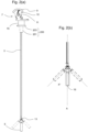
- the actuator (shown in Fig. 3 and described in detail below) is here conveniently manipulated by the operator using a thumb-pad 9 on a dial 10 which rotates around an axle 11.
- the pivotable tip is affixed to the stylet body 3 at a pivot hinge 13 which allows movement of the pivotable tip in a plane.
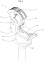
- the stylet has an attaching portion 15 located at the proximal end of the stylet, formed integrally with the body/retaining housing 17 of the actuator.
- the attaching portion here is formed as a receiving socket or plug portion which forms a plug-fit connection with an ET tube connector 200, which has a tapered portion 201 for connecting to an ET tube, and a flange portion 203.
- Fig. 2 (a) and (b) show the range of movement of the pivotable tip in this stylet.
- the tip can pivot at the pivotable hinge within a pivot range ⁇ X° from the longitudinal axis of the distal end of the stylet body, marked as axis A in Fig. 2 (b) .
- the pivot range is observed to be approximately ⁇ 45°, however depending on the exact configuration of the stylet, a pivot range of up to ⁇ 90° may be possible.
- the tip can pivot in both directions from a 'neutral' position where the tip is generally aligned with the stylet body.
- a handle portion 20 of a malleable titanium rod 19 is visible, the remainder of the rod being removably disposed within a central lumen 18 of the tubular stylet body 3.
- the malleable rod here has a rectangular cross section, with the central lumen of the stylet body being correspondingly rectangular.
- the handle has a ridged gripping portion 21 to aid removal and insertion of the rod.
- the handle portion of the rod lies within a recess formed in the body of the actuator, which can prevent the handle from obstructing the actuator during use.
- the malleable rod can either be removed from the stylet completely, or can be bent into a desired shape to aid in insertion of the stylet and ET tube through vocal cords.
- the dial of the actuator has a notch 22 which enables the malleable rod to be removed easily without obstruction by the dial.
- the stylet further has a port 35 located on the body of the actuator for attachment to an air or oxygen line.
- the port passes through the actuator body into a cavity defined by the attaching portion 15.
- air or oxygen can be provided into the ET tube via this port on the stylet.
- the port may have a ridged outer surface to help retain an oxygen line which is connected to the port.
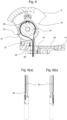
- the dial 10 has a toothed portion 27, the notches of which engage with a spring-loaded detent 29 to provide a series of incremental stop points.
- the detent 29 is on an arm pivotable about a pivot axle 31, and affixed to a spring 33 at the opposing end. Accordingly, the detent is biased into engagement with the notches on the dial 10 by the spring force of the spring.
- this rotational movement of the toothed portion of the dial forces the detent out of engagement with the notches against the spring force, until the detent can click into the subsequent notch. In this way, the mechanism allows for relatively smooth incremental adjustment of the pivot angle of the stylet tip.
- an inflatable cuff 107 is also shown.
- a cuff is a standard feature of many well-known ET tube designs, and as such, the size and shape of the cuff is not particularly limited.
- the material which the inflatable cuff is made from is not particularly limited and the skilled person will be well aware of a number of suitable materials which could be used for this purpose.
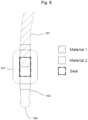
- the bending portion may not be formed of a different material, but may be made of the same material having a lower density than the body of the ET tube. Alternatively or additionally, the bending portion may be locally thinned for increased flexibility. It is also considered that any of the above proposed features of the bending portion may be used in combination.
- the bending portion may be, for example:
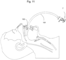
- Figs. 9 and 10 show views of an intubation kit, including a stylet of the first aspect and an ET tube of the second aspect, in addition to an ET tube connector 200.
- the ET tube shown here is an ET tube having a concertina bending portion.
- the ET tube is shown as a dashed line.
- the ET tube fits onto the tapered portion 201 of the ET tube connector.
- the position of the stylet inside the tube can be visualised.
- the location of the bending portion 103 is selected to align with the location of the pivot hinge 13 of the stylet when the stylet and the ET tube are connected.
- the length of the stylet and ET tube respectively will be selected such that the stylet does not protrude from the end of the ET tube when the ET tube is connected to the stylet. This is because where the stylet protrudes from the end of the ET tube, there is a risk that it could cause damage to a patient's airway during the intubation due to the more rigid nature of the stylet (in particular, any rigid elements at the stylet tip) in comparison to the ET tube.
- the kit can be used to perform an intubation process, including steps of a) inserting the stylet into the ET tube, b) inserting the stylet and ET tube into the airway of a patient, c) visualising the airway of the patient using the image acquisition device disposed on the stylet tip, d) guiding the ET tube and stylet through the vocal cords of the patient into the trachea of the patient, and e) removing the stylet from the ET tube.
Landscapes
- Health & Medical Sciences (AREA)
- Pulmonology (AREA)
- Life Sciences & Earth Sciences (AREA)
- Public Health (AREA)
- Engineering & Computer Science (AREA)
- Biomedical Technology (AREA)
- Heart & Thoracic Surgery (AREA)
- Animal Behavior & Ethology (AREA)
- General Health & Medical Sciences (AREA)
- Veterinary Medicine (AREA)
- Emergency Medicine (AREA)
- Anesthesiology (AREA)
- Hematology (AREA)
- Surgery (AREA)
- Otolaryngology (AREA)
- Pathology (AREA)
- Biophysics (AREA)
- Nuclear Medicine, Radiotherapy & Molecular Imaging (AREA)
- Optics & Photonics (AREA)
- Physics & Mathematics (AREA)
- Radiology & Medical Imaging (AREA)
- Medical Informatics (AREA)
- Molecular Biology (AREA)
- Rehabilitation Therapy (AREA)
- Endoscopes (AREA)
- Instruments For Viewing The Inside Of Hollow Bodies (AREA)
Claims (12)
- Stilett (1) zum Führen eines Endotrachealtubus (100) während der Intubation, wobei das Stilett Folgendes umfasst:einen Stilettkörper (3), mit einer schwenkbaren Spitze (5), die am distalen Ende des Stilettkörpers angeordnet ist, wobei die schwenkbare Spitze (5) in zwei entgegengesetzte Richtungen von der Längsachse des distalen Endes des Stilettkörpers bewegbar ist;einen Steuermechanismus, der einen Aktuator (7) am proximalen Ende des Stilettkörpers umfasst, zum Steuern des Schwenkwinkels der schwenkbaren Spitze;dadurch gekennzeichnet, dass der Aktuator ein erstes und ein zweites relativ bewegbares Element umfasst, die in Eingriff vorgespannt sind, wobei das erste relativ bewegbare Element ein drehbarer Steuerabschnitt (10) ist, der eine Reihe von Einbuchtungen aufweist, die nacheinander mit einer Schaltraste (29) des zweiten relativ bewegbaren Elements eingreifen, wenn der Steuerabschnitt gedreht wird, um so eine Vielzahl von diskreten Haltepunkten bereitzustellen, die ein Feststellen der schwenkbaren Spitze an diskreten, inkrementalen Schwenkwinkeln ermöglichen, und dass das Stilett außerdem einen verformbaren Stab (19) umfasst, der entfernbar in einem Lumen (18) des Stilettkörpers anordenbar ist, wobei der verformbare Stab einen rechteckigen Querschnitt aufweist.
- Stilett (1) nach Anspruch 1, wobei die schwenkbare Spitze (5) innerhalb eines Schwenkwinkelbereichs von zumindest ±10° bewegbar ist.
- Stilett (1) nach Anspruch 1 oder Anspruch 2, wobei der Aktuator (7) einen oder mehrere Endanschläge umfasst, die den Bewegungsbereich des Aktuators und folglich den Schwenkbereich der schwenkbaren Spitze (5) einschränken.
- Stilett (1) nach Anspruch 3, wobei die Endanschläge als Endanschläge einer Nut (14) ausgebildet sind, in der ein Stift (12) gleitet.
- Stilett (1) nach einem der Ansprüche 1 bis 4, wobei der Aktuator (7) handbetätigt ist.
- Stilett (1) nach einem der Ansprüche 1 bis 5, das einen Befestigungsabschnitt (201) umfasst, der am proximalen Ende des Stilettkörpers (3) angeordnet und ausgelegt ist, um mit einem Endotrachealtubusverbindungsteil (200) verbunden zu sein.
- Stilett (1) nach Anspruch 6, wobei der Befestigungsabschnitt (201) einstückig mit dem Körper des Aktuators (7) ausgebildet ist.
- Stilett (1) nach einem der Ansprüche 1 bis 7, wobei der Aktuator (7) mit der schwenkbaren Spitze (5) durch ein oder mehrere Steuerverbindungsteile verbunden ist, bei denen es sich um flexible Drähte (23) handelt, wobei die flexiblen Drähte zumindest einen ersten Drahtabschnitt, der mit einer Seite der schwenkbaren Spitze verbunden ist, und einen zweiten Drahtabschnitt, der mit der entgegengesetzten Seite der schwenkbaren Spitze verbunden ist, umfasst, wodurch die Spitze durch Aufbringen von mechanischer Spannung an den ersten Drahtabschnitt in die erste Richtung der beiden entgegengesetzten Richtungen bewegt werden kann, und die Spitze durch Aufbringen von mechanischer Spannung an den zweiten Drahtabschnitt in die zweite Richtung der beiden entgegengesetzten Richtungen bewegt werden kann.
- Stilett (1) nach einem der Ansprüche 1 bis 8, das eine Bilderfassungsvorrichtung (16) umfasst, die an der schwenkbaren Spitze (5) angeordnet ist.
- Stilett (1) nach einem der Ansprüche 1 bis 9, in dem die schwenkbare Spitze (5) steif ist und am distalen Ende des Stilettkörpers an einem Schwenkgelenk (13) befestigt ist.
- Intubationsset, das ein Stilett (1) nach einem der Ansprüche bis 10 und einen Endotrachealtubus (100) mit einem Körper (101), der einen flexiblen hohlen Schlauch mit einem distalen Ende (102) zum Einführen in die Luftröhre eines Patienten während einer Intubation und einem proximalen Ende zum entfernbaren Verbinden mit einem Endotrachealtubusverbindungsteil (200) umfasst, wobei der Endotrachealtubus einen Biegeabschnitt (103) umfasst, der sich am distalen Ende des Körpers befindet.
- Intubationsset nach Anspruch 11, wobei der Biegeabschnitt (103) ein Zieharmonikaabschnitt, ein lokal verdünnter Abschnitt oder ein Abschnitt aus einem anderen Material wie das Material des Körpers (101) des Endotrachealtubus (100) ist.
Applications Claiming Priority (2)
| Application Number | Priority Date | Filing Date | Title |
|---|---|---|---|
| GB1707174.7A GB2563567B (en) | 2017-05-05 | 2017-05-05 | Intubation devices |
| PCT/EP2018/061216 WO2018202720A1 (en) | 2017-05-05 | 2018-05-02 | Intubation devices |
Publications (3)
| Publication Number | Publication Date |
|---|---|
| EP3628015A1 EP3628015A1 (de) | 2020-04-01 |
| EP3628015B1 true EP3628015B1 (de) | 2024-07-03 |
| EP3628015C0 EP3628015C0 (de) | 2024-07-03 |
Family
ID=59065517
Family Applications (1)
| Application Number | Title | Priority Date | Filing Date |
|---|---|---|---|
| EP18721384.8A Active EP3628015B1 (de) | 2017-05-05 | 2018-05-02 | Stilett und intubationskit |
Country Status (7)
| Country | Link |
|---|---|
| US (2) | US11786681B2 (de) |
| EP (1) | EP3628015B1 (de) |
| CN (1) | CN110730675A (de) |
| AU (1) | AU2018262574B2 (de) |
| CA (1) | CA3062376A1 (de) |
| GB (1) | GB2563567B (de) |
| WO (1) | WO2018202720A1 (de) |
Families Citing this family (10)
| Publication number | Priority date | Publication date | Assignee | Title |
|---|---|---|---|---|
| US12108938B2 (en) * | 2013-03-15 | 2024-10-08 | Dvl, Inc. | System and device for visualization of an enclosed space |
| GB2563567B (en) | 2017-05-05 | 2022-01-05 | Flexicare Group Ltd | Intubation devices |
| US12083276B2 (en) * | 2017-12-22 | 2024-09-10 | Kalyanaraman ANANTHANARAYANAN | Tracheal intubation facilitator with superior ventilating capability |
| WO2020247386A1 (en) * | 2019-06-02 | 2020-12-10 | Wolf Technical Services, Inc. | Tube introducer intubation device |
| US11547286B2 (en) * | 2020-01-22 | 2023-01-10 | Brio13Inv. LLC | Stylet assembly |
| CN114642803A (zh) * | 2020-12-18 | 2022-06-21 | Tjb医疗股份有限公司 | 具有精确控制器的插管探针 |
| CN120152755A (zh) | 2022-09-02 | 2025-06-13 | 富利凯(集团)有限公司 | 插管装置和系统 |
| GB2618862B (en) * | 2022-09-02 | 2024-08-28 | Flexicare Group Ltd | Intubation devices and systems |
| US20250135138A1 (en) * | 2023-10-27 | 2025-05-01 | SmartAirway LLC | Articulating stylet |
| CO2024007003A1 (es) * | 2024-05-31 | 2025-12-09 | Tarazona Javier Montejo | Dispositivo óptico flexible para intubación traqueal. |
Citations (12)
| Publication number | Priority date | Publication date | Assignee | Title |
|---|---|---|---|---|
| US4207873A (en) * | 1977-05-16 | 1980-06-17 | American Cystoscope Makers, Inc. | Endoscope deflection control |
| US4880015A (en) * | 1988-06-03 | 1989-11-14 | Nierman David M | Biopsy forceps |
| US5645519A (en) * | 1994-03-18 | 1997-07-08 | Jai S. Lee | Endoscopic instrument for controlled introduction of tubular members in the body and methods therefor |
| US6432042B1 (en) * | 1998-12-11 | 2002-08-13 | Cleveland Clinic Foundation | Intubation system |
| US20030069565A1 (en) * | 2001-10-05 | 2003-04-10 | Miser John D. | Ratcheting mechanism for endoscopic instruments |
| US20050182297A1 (en) * | 1996-10-04 | 2005-08-18 | Dietrich Gravenstein | Imaging scope |
| US20120055470A1 (en) * | 2005-03-08 | 2012-03-08 | Truphatek International Ltd. | Intubation stylet |
| US8505531B2 (en) * | 2006-06-01 | 2013-08-13 | Truphatek International Ltd. | Hand operated articulated intubation stylet |
| US20160038001A1 (en) * | 2013-03-15 | 2016-02-11 | Edward R. Perez-Lizano | System and device for visualization of an enclosed space |
| WO2017076654A1 (en) * | 2015-11-06 | 2017-05-11 | Desatnik Peter | Endotracheal intubation device |
| WO2017120408A1 (en) * | 2016-01-07 | 2017-07-13 | Gardner Glenn P | Endotracheal tube insertion device |
| WO2018005776A2 (en) * | 2016-07-01 | 2018-01-04 | Brio Device Llc | Intubation stylet with video feed |
Family Cites Families (30)
| Publication number | Priority date | Publication date | Assignee | Title |
|---|---|---|---|---|
| DK165771C (da) | 1988-08-22 | 1993-06-14 | Siemssen Siems J | Endotracheal tube |
| US5549542A (en) | 1992-11-17 | 1996-08-27 | Life Medical Technologies, Inc. | Deflectable endoscope |
| US5791338A (en) | 1994-01-26 | 1998-08-11 | William T. Merchant | Endotracheal intubation apparatus |
| US5842973A (en) * | 1994-05-17 | 1998-12-01 | Bullard; James Roger | Nasal intubation apparatus |
| US5976075A (en) | 1997-12-15 | 1999-11-02 | University Of Massachusetts | Endoscope deployment apparatus |
| US20040044350A1 (en) * | 1999-04-09 | 2004-03-04 | Evalve, Inc. | Steerable access sheath and methods of use |
| US6761171B2 (en) * | 1999-09-27 | 2004-07-13 | Andrew J. Toti | Endotracheal tube with tip directional control and position preserving mechanism |
| US7789826B2 (en) | 2004-09-30 | 2010-09-07 | Boston Scientific Scimed, Inc. | Manually controlled endoscope |
| JP4912705B2 (ja) * | 2006-03-17 | 2012-04-11 | 日本コヴィディエン株式会社 | 医療用チューブ組立体 |
| US8746239B2 (en) * | 2006-07-19 | 2014-06-10 | Douglas K. Yoshida | Extendable lighted intubation stylet |
| US20080236575A1 (en) * | 2007-03-29 | 2008-10-02 | Robert Michael Chuda | Intubation device with video, stylet steering, prep and storage system |
| EP2152342A4 (de) | 2007-05-15 | 2014-02-26 | Truphatek Int Ltd | Manuell betriebener gelenkiger intubationsdorn |
| US8888683B2 (en) * | 2008-01-28 | 2014-11-18 | Mauricio Mejia | Modifications in endoscope apparatus, using fluid and gas dynamics, and methods for improving visibility during endoscopy |
| US8152719B2 (en) * | 2008-06-23 | 2012-04-10 | Intubrite, Llc | Laryngoscope and method of use |
| WO2010065566A2 (en) * | 2008-12-01 | 2010-06-10 | Stc.Unm | Intubating stylets and systems and methods for intubation |
| WO2010066789A1 (en) | 2008-12-10 | 2010-06-17 | Ambu A/S | Endoscope bending section control mechanism |
| US8336541B2 (en) * | 2009-11-24 | 2012-12-25 | Ai Medical Devices, Inc. | Endotracheal intubation device |
| US20130035548A1 (en) * | 2010-03-22 | 2013-02-07 | Tufts Medical Center, Inc. | Fiber optic intubating device |
| US8677990B2 (en) * | 2010-04-28 | 2014-03-25 | Syncro Medical Innovations, Inc. | Endo-tracheal intubation device with adjustably bendable stylet |
| CN201832258U (zh) * | 2010-10-18 | 2011-05-18 | 高宏 | 可视气管插管引导器 |
| KR101274271B1 (ko) * | 2011-04-28 | 2013-06-14 | 연세대학교 원주산학협력단 | 굴곡도의 조절이 가능한 기관튜브 |
| CA2863602A1 (en) * | 2011-05-04 | 2013-11-08 | The Regents Of The University Of Michigan | Intubation device |
| SE537098C2 (sv) * | 2013-02-08 | 2015-01-07 | Anordning för modifiering av formen hos en endotrakealtub | |
| US10307043B2 (en) * | 2013-03-15 | 2019-06-04 | Richard Rutgers | Endotracheal intubation devices |
| US10149957B2 (en) * | 2013-10-03 | 2018-12-11 | University Of Utah Research Foundation | Tracheal intubation system including a laryngoscope |
| US20150096556A1 (en) * | 2013-10-06 | 2015-04-09 | Robert S. Marks | Steerable endotracheal intubation apparatus, endotracheal intubation component system and endotracheal tube of same |
| EP3402383B1 (de) * | 2016-01-15 | 2020-04-22 | Farbes Medical, LLC | Bildgebungskompetente, bidirektional bewegliche endotrachealtubi |
| CN110022923B (zh) * | 2016-10-21 | 2022-09-27 | 声带通有限责任公司 | 铰接式管心针 |
| EP3335754A1 (de) * | 2016-12-14 | 2018-06-20 | Allytec AB | Endotracheale intubationsvorrichtung |
| GB2563567B (en) | 2017-05-05 | 2022-01-05 | Flexicare Group Ltd | Intubation devices |
-
2017
- 2017-05-05 GB GB1707174.7A patent/GB2563567B/en active Active
-
2018
- 2018-05-02 WO PCT/EP2018/061216 patent/WO2018202720A1/en not_active Ceased
- 2018-05-02 AU AU2018262574A patent/AU2018262574B2/en active Active
- 2018-05-02 US US16/610,266 patent/US11786681B2/en active Active
- 2018-05-02 CN CN201880037247.7A patent/CN110730675A/zh active Pending
- 2018-05-02 CA CA3062376A patent/CA3062376A1/en active Pending
- 2018-05-02 EP EP18721384.8A patent/EP3628015B1/de active Active
-
2023
- 2023-04-17 US US18/135,577 patent/US20230321378A1/en active Pending
Patent Citations (12)
| Publication number | Priority date | Publication date | Assignee | Title |
|---|---|---|---|---|
| US4207873A (en) * | 1977-05-16 | 1980-06-17 | American Cystoscope Makers, Inc. | Endoscope deflection control |
| US4880015A (en) * | 1988-06-03 | 1989-11-14 | Nierman David M | Biopsy forceps |
| US5645519A (en) * | 1994-03-18 | 1997-07-08 | Jai S. Lee | Endoscopic instrument for controlled introduction of tubular members in the body and methods therefor |
| US20050182297A1 (en) * | 1996-10-04 | 2005-08-18 | Dietrich Gravenstein | Imaging scope |
| US6432042B1 (en) * | 1998-12-11 | 2002-08-13 | Cleveland Clinic Foundation | Intubation system |
| US20030069565A1 (en) * | 2001-10-05 | 2003-04-10 | Miser John D. | Ratcheting mechanism for endoscopic instruments |
| US20120055470A1 (en) * | 2005-03-08 | 2012-03-08 | Truphatek International Ltd. | Intubation stylet |
| US8505531B2 (en) * | 2006-06-01 | 2013-08-13 | Truphatek International Ltd. | Hand operated articulated intubation stylet |
| US20160038001A1 (en) * | 2013-03-15 | 2016-02-11 | Edward R. Perez-Lizano | System and device for visualization of an enclosed space |
| WO2017076654A1 (en) * | 2015-11-06 | 2017-05-11 | Desatnik Peter | Endotracheal intubation device |
| WO2017120408A1 (en) * | 2016-01-07 | 2017-07-13 | Gardner Glenn P | Endotracheal tube insertion device |
| WO2018005776A2 (en) * | 2016-07-01 | 2018-01-04 | Brio Device Llc | Intubation stylet with video feed |
Non-Patent Citations (2)
| Title |
|---|
| KVALE PAUL A.: "The Flexible Bronchoscope: Which Hand Should Hold It? Pro: Left Hand", JOURNAL OF BRONCHOLOGY, vol. 10, no. 4, 1 October 2003 (2003-10-01), pages 320 - 321, XP093040861 * |
| PRIOR SIMON ET AL: "Parker Flex-Tip and Standard-Tip Endotracheal Tubes: A Comparison During Nasotracheal Intubation", ANESTHESIA PROGRESS, vol. 57, no. 1, 1 March 2010 (2010-03-01), US, pages 18 - 24, XP093056329, ISSN: 0003-3006, DOI: 10.2344/0003-3006-57.1.18 * |
Also Published As
| Publication number | Publication date |
|---|---|
| EP3628015A1 (de) | 2020-04-01 |
| US20200297957A1 (en) | 2020-09-24 |
| GB2563567A (en) | 2018-12-26 |
| WO2018202720A1 (en) | 2018-11-08 |
| AU2018262574B2 (en) | 2023-12-21 |
| US11786681B2 (en) | 2023-10-17 |
| GB2563567B (en) | 2022-01-05 |
| EP3628015C0 (de) | 2024-07-03 |
| GB201707174D0 (en) | 2017-06-21 |
| CN110730675A (zh) | 2020-01-24 |
| AU2018262574A1 (en) | 2019-12-12 |
| CA3062376A1 (en) | 2018-11-08 |
| US20230321378A1 (en) | 2023-10-12 |
Similar Documents
| Publication | Publication Date | Title |
|---|---|---|
| US20230321378A1 (en) | Intubation Devices | |
| US20230173209A1 (en) | Articulating stylet | |
| US12357167B2 (en) | Multifunctional visualization instrument with orientation control | |
| US10744288B2 (en) | Tracheal intubation system including a laryngoscope | |
| US10478578B2 (en) | Bougie with a controllable tip | |
| AU2020280985B2 (en) | Endotracheal tube insertion device | |
| US10556078B2 (en) | Camera tube with guide surface for intubation stylet and method of use | |
| EP3104923B1 (de) | Bougie zur erleichterung einer intubation | |
| US20200367722A1 (en) | System and device for visualization of an enclosed space | |
| US20110319718A1 (en) | Laryngoscope | |
| EP3335754A1 (de) | Endotracheale intubationsvorrichtung | |
| WO2020210327A1 (en) | Endotracheal tube capable of multi-directional distal deflection with stylet and endoscope securement during operation | |
| EP3335755A1 (de) | Endotracheale intubationsvorrichtung | |
| US12471914B2 (en) | Control assemblies for medical devices and related methods of use | |
| US20220379058A1 (en) | Systems, devices, and techniques for positioning tubes | |
| CN222285417U (zh) | 内窥镜 | |
| US20250072741A1 (en) | Video laryngoscopic tracheoscope | |
| GB2618625A (en) | Intubation devices and systems |
Legal Events
| Date | Code | Title | Description |
|---|---|---|---|
| STAA | Information on the status of an ep patent application or granted ep patent |
Free format text: STATUS: UNKNOWN |
|
| STAA | Information on the status of an ep patent application or granted ep patent |
Free format text: STATUS: THE INTERNATIONAL PUBLICATION HAS BEEN MADE |
|
| PUAI | Public reference made under article 153(3) epc to a published international application that has entered the european phase |
Free format text: ORIGINAL CODE: 0009012 |
|
| STAA | Information on the status of an ep patent application or granted ep patent |
Free format text: STATUS: REQUEST FOR EXAMINATION WAS MADE |
|
| 17P | Request for examination filed |
Effective date: 20191202 |
|
| AK | Designated contracting states |
Kind code of ref document: A1 Designated state(s): AL AT BE BG CH CY CZ DE DK EE ES FI FR GB GR HR HU IE IS IT LI LT LU LV MC MK MT NL NO PL PT RO RS SE SI SK SM TR |
|
| AX | Request for extension of the european patent |
Extension state: BA ME |
|
| DAV | Request for validation of the european patent (deleted) | ||
| DAX | Request for extension of the european patent (deleted) | ||
| REG | Reference to a national code |
Ref country code: HK Ref legal event code: DE Ref document number: 40023937 Country of ref document: HK |
|
| STAA | Information on the status of an ep patent application or granted ep patent |
Free format text: STATUS: EXAMINATION IS IN PROGRESS |
|
| 17Q | First examination report despatched |
Effective date: 20220513 |
|
| TPAC | Observations filed by third parties |
Free format text: ORIGINAL CODE: EPIDOSNTIPA |
|
| TPAA | Information related to observations by third parties modified |
Free format text: ORIGINAL CODE: EPIDOSCTIPA |
|
| TPAC | Observations filed by third parties |
Free format text: ORIGINAL CODE: EPIDOSNTIPA |
|
| TPAC | Observations filed by third parties |
Free format text: ORIGINAL CODE: EPIDOSNTIPA |
|
| TPAC | Observations filed by third parties |
Free format text: ORIGINAL CODE: EPIDOSNTIPA |
|
| TPAC | Observations filed by third parties |
Free format text: ORIGINAL CODE: EPIDOSNTIPA |
|
| TPAC | Observations filed by third parties |
Free format text: ORIGINAL CODE: EPIDOSNTIPA |
|
| TPAC | Observations filed by third parties |
Free format text: ORIGINAL CODE: EPIDOSNTIPA |
|
| TPAC | Observations filed by third parties |
Free format text: ORIGINAL CODE: EPIDOSNTIPA |
|
| TPAC | Observations filed by third parties |
Free format text: ORIGINAL CODE: EPIDOSNTIPA |
|
| GRAP | Despatch of communication of intention to grant a patent |
Free format text: ORIGINAL CODE: EPIDOSNIGR1 |
|
| STAA | Information on the status of an ep patent application or granted ep patent |
Free format text: STATUS: GRANT OF PATENT IS INTENDED |
|
| RIC1 | Information provided on ipc code assigned before grant |
Ipc: A61B 1/01 20060101ALN20240117BHEP Ipc: A61B 1/05 20060101ALI20240117BHEP Ipc: A61B 1/008 20060101ALI20240117BHEP Ipc: A61B 1/005 20060101ALI20240117BHEP Ipc: A61M 16/04 20060101AFI20240117BHEP |
|
| INTG | Intention to grant announced |
Effective date: 20240202 |
|
| GRAS | Grant fee paid |
Free format text: ORIGINAL CODE: EPIDOSNIGR3 |
|
| GRAA | (expected) grant |
Free format text: ORIGINAL CODE: 0009210 |
|
| STAA | Information on the status of an ep patent application or granted ep patent |
Free format text: STATUS: THE PATENT HAS BEEN GRANTED |
|
| AK | Designated contracting states |
Kind code of ref document: B1 Designated state(s): AL AT BE BG CH CY CZ DE DK EE ES FI FR GB GR HR HU IE IS IT LI LT LU LV MC MK MT NL NO PL PT RO RS SE SI SK SM TR |
|
| REG | Reference to a national code |
Ref country code: CH Ref legal event code: EP |
|
| REG | Reference to a national code |
Ref country code: DE Ref legal event code: R096 Ref document number: 602018071261 Country of ref document: DE |
|
| U01 | Request for unitary effect filed |
Effective date: 20240709 |
|
| U07 | Unitary effect registered |
Designated state(s): AT BE BG DE DK EE FI FR IT LT LU LV MT NL PT RO SE SI Effective date: 20240902 |
|
| PG25 | Lapsed in a contracting state [announced via postgrant information from national office to epo] |
Ref country code: NO Free format text: LAPSE BECAUSE OF FAILURE TO SUBMIT A TRANSLATION OF THE DESCRIPTION OR TO PAY THE FEE WITHIN THE PRESCRIBED TIME-LIMIT Effective date: 20241003 |
|
| PG25 | Lapsed in a contracting state [announced via postgrant information from national office to epo] |
Ref country code: GR Free format text: LAPSE BECAUSE OF FAILURE TO SUBMIT A TRANSLATION OF THE DESCRIPTION OR TO PAY THE FEE WITHIN THE PRESCRIBED TIME-LIMIT Effective date: 20241004 Ref country code: PL Free format text: LAPSE BECAUSE OF FAILURE TO SUBMIT A TRANSLATION OF THE DESCRIPTION OR TO PAY THE FEE WITHIN THE PRESCRIBED TIME-LIMIT Effective date: 20240703 |
|
| PG25 | Lapsed in a contracting state [announced via postgrant information from national office to epo] |
Ref country code: IS Free format text: LAPSE BECAUSE OF FAILURE TO SUBMIT A TRANSLATION OF THE DESCRIPTION OR TO PAY THE FEE WITHIN THE PRESCRIBED TIME-LIMIT Effective date: 20241103 |
|
| PG25 | Lapsed in a contracting state [announced via postgrant information from national office to epo] |
Ref country code: HR Free format text: LAPSE BECAUSE OF FAILURE TO SUBMIT A TRANSLATION OF THE DESCRIPTION OR TO PAY THE FEE WITHIN THE PRESCRIBED TIME-LIMIT Effective date: 20240703 Ref country code: CZ Free format text: LAPSE BECAUSE OF FAILURE TO SUBMIT A TRANSLATION OF THE DESCRIPTION OR TO PAY THE FEE WITHIN THE PRESCRIBED TIME-LIMIT Effective date: 20240703 |
|
| PG25 | Lapsed in a contracting state [announced via postgrant information from national office to epo] |
Ref country code: ES Free format text: LAPSE BECAUSE OF FAILURE TO SUBMIT A TRANSLATION OF THE DESCRIPTION OR TO PAY THE FEE WITHIN THE PRESCRIBED TIME-LIMIT Effective date: 20240703 Ref country code: RS Free format text: LAPSE BECAUSE OF FAILURE TO SUBMIT A TRANSLATION OF THE DESCRIPTION OR TO PAY THE FEE WITHIN THE PRESCRIBED TIME-LIMIT Effective date: 20241003 |
|
| PG25 | Lapsed in a contracting state [announced via postgrant information from national office to epo] |
Ref country code: RS Free format text: LAPSE BECAUSE OF FAILURE TO SUBMIT A TRANSLATION OF THE DESCRIPTION OR TO PAY THE FEE WITHIN THE PRESCRIBED TIME-LIMIT Effective date: 20241003 Ref country code: PL Free format text: LAPSE BECAUSE OF FAILURE TO SUBMIT A TRANSLATION OF THE DESCRIPTION OR TO PAY THE FEE WITHIN THE PRESCRIBED TIME-LIMIT Effective date: 20240703 Ref country code: NO Free format text: LAPSE BECAUSE OF FAILURE TO SUBMIT A TRANSLATION OF THE DESCRIPTION OR TO PAY THE FEE WITHIN THE PRESCRIBED TIME-LIMIT Effective date: 20241003 Ref country code: IS Free format text: LAPSE BECAUSE OF FAILURE TO SUBMIT A TRANSLATION OF THE DESCRIPTION OR TO PAY THE FEE WITHIN THE PRESCRIBED TIME-LIMIT Effective date: 20241103 Ref country code: HR Free format text: LAPSE BECAUSE OF FAILURE TO SUBMIT A TRANSLATION OF THE DESCRIPTION OR TO PAY THE FEE WITHIN THE PRESCRIBED TIME-LIMIT Effective date: 20240703 Ref country code: GR Free format text: LAPSE BECAUSE OF FAILURE TO SUBMIT A TRANSLATION OF THE DESCRIPTION OR TO PAY THE FEE WITHIN THE PRESCRIBED TIME-LIMIT Effective date: 20241004 Ref country code: ES Free format text: LAPSE BECAUSE OF FAILURE TO SUBMIT A TRANSLATION OF THE DESCRIPTION OR TO PAY THE FEE WITHIN THE PRESCRIBED TIME-LIMIT Effective date: 20240703 Ref country code: CZ Free format text: LAPSE BECAUSE OF FAILURE TO SUBMIT A TRANSLATION OF THE DESCRIPTION OR TO PAY THE FEE WITHIN THE PRESCRIBED TIME-LIMIT Effective date: 20240703 |
|
| PG25 | Lapsed in a contracting state [announced via postgrant information from national office to epo] |
Ref country code: SM Free format text: LAPSE BECAUSE OF FAILURE TO SUBMIT A TRANSLATION OF THE DESCRIPTION OR TO PAY THE FEE WITHIN THE PRESCRIBED TIME-LIMIT Effective date: 20240703 |
|
| PG25 | Lapsed in a contracting state [announced via postgrant information from national office to epo] |
Ref country code: SK Free format text: LAPSE BECAUSE OF FAILURE TO SUBMIT A TRANSLATION OF THE DESCRIPTION OR TO PAY THE FEE WITHIN THE PRESCRIBED TIME-LIMIT Effective date: 20240703 |
|
| PLBE | No opposition filed within time limit |
Free format text: ORIGINAL CODE: 0009261 |
|
| STAA | Information on the status of an ep patent application or granted ep patent |
Free format text: STATUS: NO OPPOSITION FILED WITHIN TIME LIMIT |
|
| 26N | No opposition filed |
Effective date: 20250404 |
|
| U20 | Renewal fee for the european patent with unitary effect paid |
Year of fee payment: 8 Effective date: 20250519 |
|
| REG | Reference to a national code |
Ref country code: CH Ref legal event code: H13 Free format text: ST27 STATUS EVENT CODE: U-0-0-H10-H13 (AS PROVIDED BY THE NATIONAL OFFICE) Effective date: 20251223 |
|
| PG25 | Lapsed in a contracting state [announced via postgrant information from national office to epo] |
Ref country code: CH Free format text: LAPSE BECAUSE OF NON-PAYMENT OF DUE FEES Effective date: 20250531 |
|
| GBPC | Gb: european patent ceased through non-payment of renewal fee |
Effective date: 20250502 |
|
| PG25 | Lapsed in a contracting state [announced via postgrant information from national office to epo] |
Ref country code: MC Free format text: LAPSE BECAUSE OF FAILURE TO SUBMIT A TRANSLATION OF THE DESCRIPTION OR TO PAY THE FEE WITHIN THE PRESCRIBED TIME-LIMIT Effective date: 20240703 |