EP3627239B1 - Roller display mechanism for a watch - Google Patents
Roller display mechanism for a watch Download PDFInfo
- Publication number
- EP3627239B1 EP3627239B1 EP19201623.6A EP19201623A EP3627239B1 EP 3627239 B1 EP3627239 B1 EP 3627239B1 EP 19201623 A EP19201623 A EP 19201623A EP 3627239 B1 EP3627239 B1 EP 3627239B1
- Authority
- EP
- European Patent Office
- Prior art keywords
- flap
- roller
- cam
- drive
- display
- Prior art date
- Legal status (The legal status is an assumption and is not a legal conclusion. Google has not performed a legal analysis and makes no representation as to the accuracy of the status listed.)
- Active
Links
- 230000007246 mechanism Effects 0.000 title claims description 34
- 244000027321 Lychnis chalcedonica Species 0.000 claims description 11
- 230000002093 peripheral effect Effects 0.000 claims description 10
- 230000009467 reduction Effects 0.000 claims description 10
- 230000002123 temporal effect Effects 0.000 claims description 6
- 230000008859 change Effects 0.000 claims description 4
- 239000000696 magnetic material Substances 0.000 claims description 3
- 239000011521 glass Substances 0.000 description 2
- 238000012423 maintenance Methods 0.000 description 2
- 230000035939 shock Effects 0.000 description 2
- 101100489581 Caenorhabditis elegans par-5 gene Proteins 0.000 description 1
- 240000008042 Zea mays Species 0.000 description 1
- 230000006978 adaptation Effects 0.000 description 1
- 230000000295 complement effect Effects 0.000 description 1
- 239000013078 crystal Substances 0.000 description 1
- 230000005484 gravity Effects 0.000 description 1
- 230000002035 prolonged effect Effects 0.000 description 1
- 230000003068 static effect Effects 0.000 description 1
Images


Classifications
-
- G—PHYSICS
- G04—HOROLOGY
- G04B—MECHANICALLY-DRIVEN CLOCKS OR WATCHES; MECHANICAL PARTS OF CLOCKS OR WATCHES IN GENERAL; TIME PIECES USING THE POSITION OF THE SUN, MOON OR STARS
- G04B19/00—Indicating the time by visual means
- G04B19/20—Indicating by numbered bands, drums, discs, or sheets
-
- G—PHYSICS
- G04—HOROLOGY
- G04B—MECHANICALLY-DRIVEN CLOCKS OR WATCHES; MECHANICAL PARTS OF CLOCKS OR WATCHES IN GENERAL; TIME PIECES USING THE POSITION OF THE SUN, MOON OR STARS
- G04B19/00—Indicating the time by visual means
- G04B19/24—Clocks or watches with date or week-day indicators, i.e. calendar clocks or watches; Clockwork calendars
- G04B19/243—Clocks or watches with date or week-day indicators, i.e. calendar clocks or watches; Clockwork calendars characterised by the shape of the date indicator
- G04B19/257—Clocks or watches with date or week-day indicators, i.e. calendar clocks or watches; Clockwork calendars characterised by the shape of the date indicator drum-shaped or three-dimensional shaped
- G04B19/2573—Driving or releasing mechanisms wherein the date indicators are driven or released mechanically by a clockwork movement
-
- G—PHYSICS
- G04—HOROLOGY
- G04B—MECHANICALLY-DRIVEN CLOCKS OR WATCHES; MECHANICAL PARTS OF CLOCKS OR WATCHES IN GENERAL; TIME PIECES USING THE POSITION OF THE SUN, MOON OR STARS
- G04B19/00—Indicating the time by visual means
- G04B19/20—Indicating by numbered bands, drums, discs, or sheets
- G04B19/21—Drums
-
- G—PHYSICS
- G04—HOROLOGY
- G04B—MECHANICALLY-DRIVEN CLOCKS OR WATCHES; MECHANICAL PARTS OF CLOCKS OR WATCHES IN GENERAL; TIME PIECES USING THE POSITION OF THE SUN, MOON OR STARS
- G04B19/00—Indicating the time by visual means
- G04B19/20—Indicating by numbered bands, drums, discs, or sheets
- G04B19/205—Indicating by numbered bands, drums, discs, or sheets by means of sheets
-
- G—PHYSICS
- G04—HOROLOGY
- G04B—MECHANICALLY-DRIVEN CLOCKS OR WATCHES; MECHANICAL PARTS OF CLOCKS OR WATCHES IN GENERAL; TIME PIECES USING THE POSITION OF THE SUN, MOON OR STARS
- G04B19/00—Indicating the time by visual means
- G04B19/20—Indicating by numbered bands, drums, discs, or sheets
- G04B19/207—Indicating by numbered bands, drums, discs, or sheets by means of bands
-
- G—PHYSICS
- G04—HOROLOGY
- G04B—MECHANICALLY-DRIVEN CLOCKS OR WATCHES; MECHANICAL PARTS OF CLOCKS OR WATCHES IN GENERAL; TIME PIECES USING THE POSITION OF THE SUN, MOON OR STARS
- G04B19/00—Indicating the time by visual means
- G04B19/24—Clocks or watches with date or week-day indicators, i.e. calendar clocks or watches; Clockwork calendars
- G04B19/243—Clocks or watches with date or week-day indicators, i.e. calendar clocks or watches; Clockwork calendars characterised by the shape of the date indicator
- G04B19/24386—Clocks or watches with date or week-day indicators, i.e. calendar clocks or watches; Clockwork calendars characterised by the shape of the date indicator sheet-shaped
- G04B19/24393—Driving or releasing mechanisms wherein the date indicators are driven or released mechanically by a clockwork movement
-
- G—PHYSICS
- G09—EDUCATION; CRYPTOGRAPHY; DISPLAY; ADVERTISING; SEALS
- G09F—DISPLAYING; ADVERTISING; SIGNS; LABELS OR NAME-PLATES; SEALS
- G09F11/00—Indicating arrangements for variable information in which the complete information is permanently attached to a movable support which brings it to the display position
- G09F11/02—Indicating arrangements for variable information in which the complete information is permanently attached to a movable support which brings it to the display position the display elements being secured to rotating members, e.g. drums, spindles
- G09F11/04—Indicating arrangements for variable information in which the complete information is permanently attached to a movable support which brings it to the display position the display elements being secured to rotating members, e.g. drums, spindles the elements being secured to rotating discs
-
- G—PHYSICS
- G09—EDUCATION; CRYPTOGRAPHY; DISPLAY; ADVERTISING; SEALS
- G09F—DISPLAYING; ADVERTISING; SIGNS; LABELS OR NAME-PLATES; SEALS
- G09F11/00—Indicating arrangements for variable information in which the complete information is permanently attached to a movable support which brings it to the display position
- G09F11/02—Indicating arrangements for variable information in which the complete information is permanently attached to a movable support which brings it to the display position the display elements being secured to rotating members, e.g. drums, spindles
- G09F11/06—Indicating arrangements for variable information in which the complete information is permanently attached to a movable support which brings it to the display position the display elements being secured to rotating members, e.g. drums, spindles the elements being stiff plates or cards
Description
L'invention concerne un mécanisme d'affichage d'horlogerie comportant au moins un rouleau pivotant autour d'un axe de rouleau, le rouleau comportant au moins un volet pivotant autour d'un axe de volet parallèle à l'axe de rouleau et distinct de l'axe de rouleau, ledit au moins un volet comportant au moins une première face et au moins une deuxième face, le mécanisme d'affichage comportant des premiers moyens d'entraînement pour faire pivoter le rouleau autour de l'axe de rouleau, où ledit mécanisme d'affichage comporte des deuxièmes moyens d'entraînement distincts desdits premiers moyens d'entraînement pour faire pivoter au moins un dit volet autour de son dit axe de volet, dans au moins une position déterminée dudit axe de volet par rapport audit axe de rouleau.The invention relates to a timepiece display mechanism comprising at least one roller pivoting around a roller axis, the roller comprising at least one flap pivoting around a shutter axis parallel to the roller axis and distinct of the roller axis, said at least one flap comprising at least one first face and at least one second face, the display mechanism comprising first drive means for pivoting the roller around the roller axis, where said display mechanism comprises second drive means distinct from said first drive means for pivoting at least one said shutter around its said shutter axis, in at least one determined position of said shutter axis relative to said axis of roller.
L'invention concerne encore une montre comportant au moins un tel mécanisme d'affichage.The invention also relates to a watch comprising at least one such display mechanism.
L'invention concerne le domaine des mécanismes d'affichage d'horlogerie, notamment pour montres, et plus particulièrement les mécanismes d'affichage de calendrier.The invention relates to the field of timepiece display mechanisms, in particular for watches, and more particularly calendar display mechanisms.
La lisibilité des affichages est une préoccupation majeur en horlogerie, surtout pour les affichages de type calendrier, qui sont difficiles à réaliser dans des formats facilement visibles et déchiffrables par l'utilisateur.The readability of displays is a major concern in watchmaking, especially for calendar-type displays, which are difficult to produce in formats that are easily visible and decipherable by the user.
Les affichages horlogers sont rarement réalisés par rouleaux car les indications sous cette forme sont gourmandes en épaisseur, en raison du diamètre du rouleau, comportant par exemple jusqu'à 31 indications pour les jours du mois, ou 52 indications pour les semaines de l'année, et incompatibles avec la géométrie particulière d'une montre.Watch displays are rarely made by rollers because the indications in this form are demanding in thickness, due to the diameter of the roller, comprising for example up to 31 indications for the days of the month, or 52 indications for the weeks of the year , and incompatible with the particular geometry of a watch.
Et l'emploi éventuel de caractères de très petite taille nécessite l'emploi de loupes dans l'épaisseur de la glace de montre, qui nuisent fortement à l'esthétique de la montre, tout en restant difficiles à lire.And the possible use of very small characters requires the use of magnifying glasses in the thickness of the watch glass, which greatly harm the aesthetics of the watch, while remaining difficult to read.
Les affichages à volet ou à palettes, de type statique, pour pendulettes et autres horloges, sont peu transposables à des montres, car faisant généralement appel à la gravité. Ils sont de plus fragiles et ne peuvent supporter les chocs.Shutter or paddle displays, of the static type, for clocks and other clocks, are difficult to transpose to watches, because they generally rely on gravity. They are more fragile and cannot withstand shocks.
Le document
Le document
Le document
Le document
L'invention se propose de développer un affichage à rouleau, avec des indications horlogères lisibles malgré le diamètre limité des rouleaux.The invention aims to develop a roller display, with timepiece indications readable despite the limited diameter of the rollers.
A cet effet, l'invention concerne un mécanisme d'affichage d'horlogerie comportant au moins un rouleau pivotant autour d'un axe de rouleau, ledit rouleau comportant au moins un volet pivotant autour d'un axe de volet parallèle audit axe de rouleau et distinct dudit axe de rouleau, ledit au moins un volet comportant au moins une première face et au moins une deuxième face, ledit mécanisme d'affichage comportant des premiers moyens d'entraînement pour faire pivoter ledit rouleau autour dudit axe de rouleau, où ledit mécanisme d'affichage comporte des deuxièmes moyens d'entraînement distincts desdits premiers moyens d'entraînement pour faire pivoter au moins un dit volet autour de son dit axe de volet, dans au moins une position déterminée dudit axe de volet par rapport audit axe de rouleau, caractérisé en ce que lesdits premiers moyens d'entraînement comportent une roue de commande dont certaines dents sont supprimées, et qui engrène avec un pignon d'entraînement de rouleau, soit directement, soit par l'intermédiaire d'un couple de réduction, pour obtenir la réduction voulue.To this end, the invention relates to a clock display mechanism comprising at least one roller pivoting around a roller axis, said roller comprising at least one flap pivoting around a shutter axis parallel to said roller axis and distinct from said roller axis, said at least one flap comprising at least one first face and at least one second face, said display mechanism comprising first drive means for pivoting said roller around said roller axis, where said display mechanism comprises second drive means distinct from said first drive means for pivoting at least one said shutter around its said shutter axis, in at least one determined position of said shutter axis relative to said roller axis , characterized in that said first drive means comprise a control wheel of which certain teeth are removed, and which meshes with a roller drive pinion, either directly or via a reduction torque, to obtain the desired reduction.
L'invention concerne encore une montre comportant au moins un tel mécanisme d'affichage.The invention also relates to a watch comprising at least one such display mechanism.
D'autres caractéristiques et avantages de l'invention apparaîtront à la lecture de la description détaillée qui va suivre, en référence aux dessins annexés, où :
- la
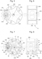
figure 1 représente, de façon schématisée, et en vue de face, une montre comportant un mécanisme d'affichage à rouleaux selon l'invention, de type calendrier ; - la
figure 2 représente, de façon similaire à lafigure 1 , un affichage de quantième sur un rouleau des dizaines et un rouleau des unités à volets selon l'invention ; - la
figure 3 représente, de façon similaire à lafigure 1 , le rouage d'entraînement du rouleau des dizaines de lafigure 2 ; - la
figure 4 représente, de façon similaire à lafigure 1 , le rouage d'entraînement du rouleau des unités de lafigure 2 ; - la
figure 5 représente, de façon schématisée, et en vue de bout dans un plan perpendiculaire à l'axe de rotation du rouleau, le rouleau des unités de lafigure 2 , avec en trait interrompu la cinématique de pivotement d'un des volets de ce rouleau; - la
figure 6 représente, de façon similaire à lafigure 1 , un détail du rouleau des unités de lafigure 5 ; - la
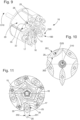
figure 7 représente, de façon similaire à lafigure 5 , une variante du rouleau des unités de lafigure 2 , montrant les moyens d'entraînement et de maintien des volets, avec en trait interrompu la cinématique de pivotement d'un des volets de ce rouleau ; - la
figure 8 représente, de façon similaire à lafigure 1 , un détail du rouleau des unités de lafigure 7 ; - la
figure 9 représente, de façon schématisée, et en perspective, le rouleau des unités de lafigure 7 ; - les
figures 10 et 11 représentent, de façon schématisée, respectivement en coupe et en vue de bout, dans un plan perpendiculaire à l'axe de rotation du rouleau, le rouleau des unités de lafigure 7 , dans une position intermédiaire, avec, également visible sur lafigure 9 , la représentation d'un ressort agencé pour exercer un effort sur des sautoirs disposé à proximité de cames de volet pour l'indexage en position de ces cames et des volets correspondants; - les
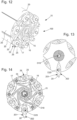
figures 12 à 14 représentent, de façon similaire auxfigures 9 à 11 , un rouleau des mois selon l'invention ; - la
figure 15 représente, de façon similaire auxfigures 3 et 4 , la rotation d'un rouleau des unités à cinq volets ; - la
figure 16 représente, de façon similaire à lafigure 15 , la commande de rotation d'un rouleau particulier à sept indications, correspondant aux jours de la semaine ; - la
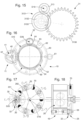
figure 17 représente, de façon similaire à lafigure 7 , une autre variante du rouleau des unités de lafigure 2 , montrant les moyens d'entraînement et de maintien magnétique des volets, avec en trait interrompu la cinématique de pivotement d'un des volets de ce rouleau ; - la
figure 18 représente, de façon similaire à lafigure 8 , un détail du rouleau des unités de lafigure 17 ; - les
figures 19 et 20 illustrent une autre variante, qui comporte, en lieu et place des systèmes à croix de Malte décrits ci-dessus, des dentures partielles ; - la
figure 21 représente, de façon similaire à lafigure 5 , une variante avec laquelle l'indexage en position des cames de volet est effectué par un unique ressort faisant aussi fonction de sautoir ; - les
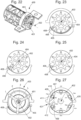
figures 22 à 26 représentent, de façon schématisée, une variante pour l'affichage des années bissextiles :- la
figure 22 en perspective montant une triple aiguille à 120°, dans le prolongement de l'axe du rouleau des mois ; - la
figure 23 , en coupe perpendiculaire à cet axe, montre une étoile, maintenue par un sautoir, qui entraîne cette aiguille triple ; - les
figures 24 et 25 montrent, de façon similaire à lafigure 23 , mais sans représentation du sautoir, la coopération de l'étoile, pour son entraînement, par un levier excentré solidaire d'un volet ; - la
figure 26 est une vue de bout, du côté de l'aiguille triple ; - la
figure 27 représente, de façon similaire à lafigure 7 , une autre variante de maintien des volets sans sautoir, et avec entraînement par une denture partielle, avec un guidage par une circonférence extérieure en contact avec le volet lui-même.
- la
- there
figure 1 represents, schematically and in front view, a watch comprising a roller display mechanism according to the invention, of the calendar type; - there
figure 2 represents, similarly to thefigure 1 , a date display on a tens roller and a shutter unit roller according to the invention; - there
Figure 3 represents, similarly to thefigure 1 , the drive cog of the tens roller of thefigure 2 ; - there
Figure 4 represents, similarly to thefigure 1 , the drive cog of the roller units of thefigure 2 ; - there
Figure 5 represents, schematically, and in end view in a plane perpendicular to the axis of rotation of the roller, the roller of the units of thefigure 2 , with broken lines showing the pivoting kinematics of one of the flaps of this roller; - there
Figure 6 represents, similarly to thefigure 1 , a detail of the roll of the units of thefigure 5 ; - there
Figure 7 represents, similarly to theFigure 5 , a variant of the roll of units of thefigure 2 , showing the means for driving and maintaining the flaps, with broken lines showing the pivoting kinematics of one of the flaps of this roller; - there
figure 8 represents, similarly to thefigure 1 , a detail of the roll of the units of theFigure 7 ; - there
Figure 9 represents, schematically and in perspective, the roll of units of theFigure 7 ; - THE
figures 10 and 11 represent, schematically, respectively in section and in end view, in a plane perpendicular to the axis of rotation of the roller, the roller of the units of theFigure 7 , in an intermediate position, with, also visible on theFigure 9 , the representation of a spring arranged to exert a force on jumpers arranged near shutter cams for indexing the position of these cams and the corresponding shutters; - THE
figures 12 to 14 represent, in a similar way tofigures 9 to 11 , a scroll of the months according to the invention; - there
Figure 15 represents, in a similar way tofigures 3 and 4 , the rotation of a roller of five-pronged units; - there
Figure 16 represents, similarly to theFigure 15 , the rotation control of a particular roller with seven indications, corresponding to the days of the week; - there
Figure 17 represents, similarly to theFigure 7 , another variation of the roll of units of thefigure 2 , showing the means for driving and magnetically holding the shutters, with broken lines showing the pivoting kinematics of one of the shutters of this roller; - there
Figure 18 represents, similarly to thefigure 8 , a detail of the roll of the units of theFigure 17 ; - THE
figures 19 and 20 illustrate another variant, which includes, instead of the Maltese cross systems described above, partial teeth; - there
Figure 21 represents, similarly to thefigure 5 , a variant with which the position indexing of the shutter cams is carried out by a single spring also acting as a jumper; - THE
figures 22 to 26 represent, schematically, a variant for displaying leap years:- there
Figure 22 in perspective mounting a triple hand at 120°, in the extension of the axis of the month roll; - there
Figure 23 , in section perpendicular to this axis, shows a star, held by a necklace, which drives this triple needle; - THE
figures 24 and 25 show, similarly to theFigure 23 , but without representation of the saltire, the cooperation of the star, for its drive, by an eccentric lever secured to a shutter; - there
Figure 26 is an end view, from the side of the triple needle; - there
figure 27 represents, similarly to thefigure 7 , another variant of maintaining the shutters without jumper, and with drive by partial teeth, with guidance by an external circumference in contact with the shutter itself.
- there
L'invention est illustrée sur les figures, de façon non limitative, avec des rouleaux des jours de la semaine, du quantième (un rouleau des dizaines et un rouleau des unités), et des mois.The invention is illustrated in the figures, in a non-limiting manner, with rolls for the days of the week, the date (a tens roll and a units roll), and months.
La
Ainsi, l'invention concerne un mécanisme d'affichage 100 d'horlogerie comportant au moins un rouleau 10, prenant sur les figures des références différenciées : 11, 12, 13, 14, pivotant autour d'un axe de rouleau D10. Ce rouleau 10, 11, 12, 13, 14 comporte au moins un volet 20, qui est monté pivotant autour d'un axe de volet D20 parallèle à l'axe de rouleau D10 et distinct de l'axe de rouleau D10. Cet au moins un volet 20 comporte au moins une première face 201 et au moins une deuxième face 202, agencées de façon à ce que l'utilisateur puisse visualiser une seule de ces faces à un instant donné.Thus, the invention relates to a
Le mécanisme d'affichage 100 comporte des premiers moyens d'entraînement 31 pour faire pivoter le rouleau 10, 11, 12, 13, 14, autour de l'axe de rouleau D10.The
Ce mécanisme d'affichage 100 comporte des deuxièmes moyens d'entraînement 32, distincts des premiers moyens d'entraînement 31, pour faire pivoter au moins un tel volet 20 autour de son axe de volet D20, dans au moins une position déterminée de l'axe de volet D20 par rapport à l'axe de rouleau D10.This
Selon l'invention, dans ce mécanisme d'affichage 100, une rotation constante des volets 20 en fonction des rouleaux 10, 11, 12, 13, 14, est calculée pour que, à la position d'affichage visible par l'utilisateur, l'indication du volet 20 soit tournée de 180° par tour de rouleau 10, 11, 12, 13, 14.According to the invention, in this
Plus particulièrement, dans un mode qui ne fait pas parti de l'invention, les deuxièmes moyens d'entraînement 32 sont agencés pour faire pivoter un seul volet 20 à la fois, indépendamment des autres volets 20 que comporte un rouleau 10, 11, 12, 13, 14.More particularly, in a mode which is not part of the invention, the second drive means 32 are arranged to pivot a
Selon l'invention, les deuxièmes moyens d'entraînement 32 sont agencés pour faire pivoter de façon synchrone chaque volet 20 que comporte un rouleau 10, 11, 12, 13, 14. Ceci permet d'économiser l'énergie nécessaire au mécanisme d'affichage.According to the invention, the second drive means 32 are arranged to pivot synchronously each
Dans une variante ne faisant pas partie de l'invention telle que revendiquée, et étant moins consommatrice d'espace, les deuxièmes moyens d'entraînement 32 sont agencés pour faire pivoter un seul volet 20 à la fois, plus particulièrement, les deuxièmes moyens d'entraînement 32 sont agencés pour faire pivoter le seul volet 20 en une unique position déterminée de l'axe de volet D20 par rapport à l'axe de rouleau D10.In a variant not forming part of the invention as claimed, and being less space consuming, the second drive means 32 are arranged to pivot a
Plus particulièrement, les deuxièmes moyens d'entraînement 32 comportent, au niveau de chaque volet 20, au moins un pignon d'entraînement de volet 35 axé sur l'axe de volet D20. Ce pignon d'entraînement de volet 35 est plus particulièrement agencé pour coopérer avec un moyen de commande, que comporte le mécanisme d'affichage 100, pour modifier en séquence ou en continu la position des volets 20 successifs d'un même rouleau 10, 11, 12, 13, 14, ou pour modifier à la demande la position d'un volet 20 déterminé. Il est ainsi possible de modifier à la demande la position d'un volet déterminé.More particularly, the second drive means 32 comprise, at each
Tout particulièrement, une motorisation des deuxièmes moyens d'entraînement 32, ou une commande par une tige de montre, ou un poussoir, une targette, ou similaire, facilite la mise à jour d'un calendrier après un arrêt prolongé d'une montre.In particular, motorization of the second drive means 32, or control by a watch stem, or a pusher, a bolt, or the like, facilitates the updating of a calendar after a prolonged stopping of a watch.
Plus particulièrement, chaque volet 20 comporte, pour son maintien en position d'orientation, une came de volet 25, notamment une came-coeur, comportant autant de points bas 26 que le volet 20 comporte de faces 201, 202. Et le rouleau 10, 11, 12, 13, 14, comporte de préférence au moins un ressort 15 qui est agencé pour exercer un effort sur un sautoir 17 disposé à proximité de chaque came de volet pour l'indexage en position de cette came de volet 25, tel que visible sur les
Dans une variante particulière, tel que visible sur la
Dans une variante de fonctionnalité similaire, plus particulièrement, chaque volet 20 comporte, pour son maintien en position d'orientation, une came de volet 25 ou une came-coeur comportant autant de points bas 26 que le volet 20 comporte de faces 201, 202, et le rouleau 10, 11, 12, 13, 14 comporte, pour chaque came de volet 25 ou came-coeur, au moins un aimant 70 agencé pour exercer un effort sur la came de volet 25 ou came-coeur en matériau magnétique pour l'indexage en position de la came de volet 25 ou came-coeur, tel que visible sur la
Plus particulièrement, selon l'invention, les premiers moyens d'entraînement 31 comportent, tel que visible sur les
Plus particulièrement, au moins un rouleau 10, 11, 12, 13, 14, comporte au moins une position fixe d'affichage et au moins une position mobile d'affichage par un volet 20 comportant une pluralité de faces 201, 202, tel que visible sur la
Plus particulièrement, les premiers moyens d'entraînement 31 comportent un rouage d'entrée 61 qui entraîne une roue principale 60 dont une révolution correspond à la période temporelle d'affichage du rouleau 10, 11, 12, 13, 14, et qui porte une came principale 50 porteuse de secteurs périphériques 51 séparés par des évidements 52, les secteurs périphériques 51 étant d'amplitude inégale, les plus courts correspondant aux positions fixes d'affichage, et les plus longs correspondant aux positions mobiles d'affichage. La came principale 50 coopère avec une came secondaire 40 en croix de Malte excentrée et agencée pour pivoter lors du passage d'un évidement 52. La came secondaire 40 porte une roue secondaire 42 engrenant avec une roue d'entraînement de rouleau 62. La roue principale 60 porte encore une roue principale d'entraînement de volet 63, laquelle engrène elle-même avec un pignon de volet 64 qui est agencé pour commander un pignon d'entraînement de volet 35 axé sur l'axe de volet D20 ou constituant lui-même un tel pignon d'entraînement de volet 35.More particularly, the first drive means 31 comprise an
L'invention concerne encore une montre 1000 comportant au moins un tel mécanisme d'affichage 100.The invention also relates to a
Les figures illustrent des modes de réalisation particuliers de l'invention.The figures illustrate particular embodiments of the invention.
La
L'entraînement des deux rouleaux se fait par deux roues de commande 3120 et 3130, de 31 dents chacune, où des dents sont supprimées, en correspondance des jours où aucune rotation du rouleau respectif n'est nécessaire.The driving of the two rollers is done by two
La
La
Ces principes d'entraînement sont semblables à ceux, bien connus, des affichages de quantième à grand guichets.These training principles are similar to those, well known, of date displays with large windows.
Les
Les
Les volets 20 peuvent être entraînés en rotation continue relativement à la rotation du rouleau 10, avec un rapport de un demi. Cette solution est simple mais demande de la place sur toute la circonférence du rouleau 10, ce qui n'est pas toujours possible.The
Pour limiter l'encombrement du système, il est avantageux d'utiliser la solution décrite ci-après, qui gère une rotation d'un volet 20 en un seul point de la circonférence du rouleau 10. Chaque volet 20 est alors maintenu en position par un sautoir 17, qui collabore avec une came de volet 25, notamment de type came-coeur, à deux positions, montée sur l'axe du volet concerné, dont le point bas 26 coopère avec un saillant du sautoir 17. Un ressort 15, notamment comme sur la
Ce pignon 35 peut être entraîné par un rouage que comportent les deuxièmes moyens d'entraînement 32, non illustré sur les figures. Dans la variante particulière de la
Les
La
- 3130
de 31 dents : 1 tour par mois - 3132
de 10 dents : 1tour par 10 jours - 3133
de 20 dents : 1tour par 10 jours - 313
de 10 dents : 1 tour par 5 jours
- 3130 of 31 teeth: 1 revolution per month
- 3132 of 10 teeth: 1 turn per 10 days
- 3133 of 20 teeth: 1 turn per 10 days
- 313 of 10 teeth: 1 turn per 5 days
Dans un mode de réalisation particulier à croix de Malte, les premiers moyens d'entraînement 31 comportent un rouage d'entrée 61 qui entraîne une roue principale 60 dont une révolution correspond à la période temporelle d'affichage du rouleau 10, 11, 12, 13, 14, et qui porte une came principale 50 porteuse de secteurs périphériques de géométrie inégale, des secteurs concentriques 51 correspondant aux positions fixes d'affichage, et des secteurs avec évidements 52 et munis de goupilles d'entraînement 5X correspondant aux positions mobiles du rouleau d'affichage10, 11, 12, 13, 14. Cette came principale 50 coopère avec une came secondaire 40 en croix de Malte excentrée, pivotant autour d'un point fixe, et agencée pour pivoter lors du passage d'un évidement 52 et d'une goupille 5X. Cette came secondaire 40 porte une roue secondaire 42 engrenant avec une roue d'entraînement de rouleau 62, et la roue principale 60 porte encore une roue principale d'entraînement de volet 63, laquelle engrène elle-même avec un pignon de volet 64 agencé pour commander un pignon d'entraînement de volet 35 axé sur l'axe de volet D20 ou constituant lui-même un pignon d'entraînement de volet 35.In a particular embodiment with a Maltese cross, the first drive means 31 comprise an
Plus particulièrement, la
- rouleau avec six positions fixes et un volet à deux faces ;
- rouleau avec cinq positions fixes et deux volets à deux faces ;
- rouleau avec quatre positions fixes et trois volets à deux faces ;
- rouleau avec une position fixe et deux volets à trois faces ;
- roller with six fixed positions and a two-sided shutter;
- roller with five fixed positions and two two-sided flaps;
- roller with four fixed positions and three two-sided flaps;
- roller with a fixed position and two three-sided flaps;
La
Plus généralement, pour un affichage de N périodes, la roue principale 60 est entraînée de 1/N de tour par jour.More generally, for a display of N periods, the
La roue principale 60 porte une came principale 50, qui est séparée en N secteurs périphériques différents. Ces secteurs périphériques sont de géométrie inégale : des secteurs concentriques 51 correspondent aux positions fixes d'affichage, et des secteurs avec évidements 52 et munis de goupilles d'entraînement 5X correspondent aux positions mobiles du rouleau d'affichage. De plus, l'amplitude angulaire des secteurs concentriques 51 peut être variable, comme on le verra plus loin.The
Cette came principale 50 coopère avec une came secondaire 40 en croix de Malte, par les goupilles et les encoches mentionnées ci-dessus. Cette came secondaire 40 est excentrée, pivote autour d'un point fixe, et est agencée pour pivoter lors du passage d'un évidement 52 et d'une goupille 5X.This
Cette came secondaire 40 porte une roue secondaire 42 qui engrène avec une roue d'entraînement de rouleau 62, elle-même solidaire du rouleau d'affichage 10 concerné.This
La came secondaire 40 en croix de Malte entraîne ainsi, six jours sur sept, cette roue d'entraînement de rouleau 62 de 1/6 de tour, ce qui correspond aux six positions fixes du rouleau.The secondary
Le septième jour, la portée 41 de la came secondaire 40 en croix de Malte reste en appui sur le plus long 510 des secteurs concentriques 51, et la came secondaire 40 en croix de Malte ne peut donc pas pivoter. La roue d'entraînement de rouleau 62 n'est pas entraînée, et le rouleau reste alors immobile.On the seventh day, the bearing 41 of the
La roue principale 60 porte encore une roue principale d'entraînement de volet 63, laquelle engrène elle-même avec un pignon de volet 64 agencé pour commander un pignon d'entraînement de volet 35 axé sur l'axe de volet D20, ou bien constituant lui-même un pignon d'entraînement de volet 35.The
Cette roue principale d'entraînement de volet 63 effectue, comme la roue principale 60, 1/7 de tour par jour.This main
Le pignon de volet 64 porte le volet 20 à deux faces, et engrène avec un rapport de 3.5 avec la roue principale d'entraînement de volet 63.The
Donc, lorsque la roue d'entraînement de rouleau 62 est immobile, et que la roue principale 60 fait 1/7 de tour, le pignon de volet 64 fait 1/2 tour, avec changement de côté du volet 20.Therefore, when the
Lorsque la roue d'entraînement de rouleau 62 est libérée et fait 1/6 de tour et que la roue principale 60 fait 1/7 de tour, le pignon de volet 64 fait 1/12 de tour, donc en six jours reprendra sa place de départ.When the
Les
Dans un autre mode de réalisation particulier à dentures partielles, en lieu et place des systèmes à croix de Malte décrits ci-dessus, les premiers moyens d'entraînement 31 comportent un rouage d'entrée 61 qui entraîne une roue principale 60 dont une révolution correspond à la période temporelle d'affichage du rouleau 10, 11, 12, 13, 14, et qui porte une came principale 50 porteuse de secteurs périphériques de géométrie inégale: des secteurs concentriques 51 correspondant aux positions fixes d'affichage, et des secteurs comportant des moyens d'entraînement 53 voisins d'évidements 52. La came principale 50 coopère avec une étoile 71 excentrée, pivotant autour d'un point fixe, et agencée pour pivoter lors du passage d'un tel moyen d'entraînement 53, et pour rester dans sa position angulaire quand deux dents 72 qu'elle comporte sont en appui sur un secteur concentrique 51. Cette étoile 71 porte une roue secondaire 70, qui engrène avec une roue d'entraînement de rouleau 62 elle-même solidaire du rouleau 10, 11, 12, 13, 14. La roue principale 60 porte, comme précédemment, une roue principale d'entraînement de volet 63, laquelle engrène elle-même avec un pignon de volet agencé pour commander un pignon d'entraînement de volet 35 axé sur l'axe de volet D20 ou constituant lui-même un pignon d'entraînement de volet 35.In another particular embodiment with partial teeth, instead of the Maltese cross systems described above, the first drive means 31 comprise an
Plus particulièrement, les
Un pignon entraîneur du rouage d'entrée 61 non représenté effectue 1 tour par jour, et entraîne une roue principale 60, qui fait 1/N, soit ici 1/7 tour par jour.A driving pinion of the
La roue principale 60 porte une came principale 50, qui est séparée en sept secteurs périphériques différents, les secteurs périphériques comportant ou non des moyens d'entraînement (ici constitués par des dents 53), les secteurs concentriques 51 correspondant aux positions fixes d'affichage du rouleau 20, et les secteurs avec moyens d'entraînement 53 correspondant aux positions mobiles du rouleau d'affichage.The
Cette came principale 50 coopère avec une étoile 71 de 4 dents, maintenue par un sautoir non représenté. Cette étoile de quatre 71 est excentrée, pivote autour d'un point fixe, elle est agencée pour pivoter lors du passage d'un moyen d'entraînement, notamment d'une dent dans la réalisation illustrée, non limitative.This
Les moyens d'entraînement 53 comportant ici des dents, et de préférence combinés à des évidements 52, sont agencés pour engrener avec des dents 72 de l'étoile de quatre 71. Par contre, quand deux dents 72 successives de l'étoile de quatre 71 sont simultanément en appui sur un secteur concentrique 51, l'étoile de quatre 71 ne peut pas tourner.The drive means 53 here comprising teeth, and preferably combined with
L'étoile de quatre 71, pivotée sur la platine, est ainsi agencée pour effectuer 1/4 de tour par jour, sauf deux jours par semaine. Dans l'exemple illustré, quand cette étoile 71 a pivoté du lundi au mardi, elle reste dans sa position le mardi et le mercredi, avant de changer de position entre le mercredi et le jeudi. De la même façon, quand l'étoile 71 a pivoté du vendredi au samedi, elle reste dans sa position le samedi et le dimanche, avant de changer de position entre le dimanche et le lundi. Le volet 20B affichera une première position le mardi, pivotera de 180° du mardi au mercredi, pour afficher une deuxième position le mercredi. De la même façon, le volet 20E affichera une première position le samedi, pivotera de 180° du samedi au dimanche, pour afficher une deuxième position le dimanche. Les autres jours, l'utilisateur verra des affichages fixes en périphérie du rouleau 20 : 20A le lundi, 20C le jeudi, 20D le vendredi.The four
Cette étoile de quatre 71 porte une roue secondaire 70, qui engrène avec une roue d'entraînement de rouleau 62, elle-même solidaire du rouleau d'affichage 10.This four
L'étoile de quatre dents 71 entraîne de fait, cinq jours sur sept, cette roue d'entraînement de rouleau 62 de 1/5 de tour, ce qui correspond aux cinq positions fixes du rouleau.The four-
Les deux jours supplémentaires, l'étoile de quatre 71 reste en appui sur les secteurs concentriques 51, et ne peut donc pas pivoter. La roue d'entraînement de rouleau 62 n'est pas entraînée, et le rouleau 10 reste alors immobile.The two additional days, the four
La roue principale 60 porte encore une roue principale d'entraînement de volet 63, laquelle engrène elle-même avec un pignon de volet agencé pour commander un pignon d'entraînement de volet axé sur l'axe de volet D20, ou bien constituant lui-même un pignon d'entraînement de volet 35.The
Cette roue principale d'entraînement de volet 63 effectue, comme la roue principale, 1/7 de tour par jour.This main
Les pignons de volets portent les volets 20B et 20E à deux faces, et engrènent avec un rapport de 3.5 avec la roue principale d'entraînement de volet 63.The flap pinions carry the
Donc, lorsque la roue d'entraînement de rouleau 62 est immobile, et que la roue principale 60 fait 1/7 de tour, le pignon de volet fait 1/2 tour, avec changement de côté du volet 20 concerné.Therefore, when the
Lorsque la roue d'entraînement de rouleau 62 est libérée et fait 1/5 de tour et que la roue principale 60 fait 1/7 de tour, le pignon de volet fait 1/10 de tour, donc en 5 jours reprendra sa place de départ.When the
Les
La
De la même manière, dans une variante de volet sans sautoir, le volet peut être guidé directement par une circonférence extérieure en contact avec le volet lui-même. De cette façon, la circonférence de guidage est interrompue pour laisser passer le volet. Le pignon d'entraînement peut alors se retrouver dans la configuration de la variante des
Les différentes variantes de l'invention permettent de réaliser des affichages à rouleaux de toutes sortes d'indications dans le volume réduit d'une montre de dimension normale, avec notamment une épaisseur totale de l'ordre de 10 mm à l'extérieur des glaces, ou de la glace et du fond. Les volets ne sont en contact avec aucune partie de la montre, et ne sont soumis à aucun choc ou frottement dans le cadre de leur fonctionnement normal.The different variants of the invention make it possible to produce roller displays of all kinds of indications in the reduced volume of a normal-sized watch, in particular with a total thickness of around 10 mm outside the crystals. , or ice and bottom. The shutters are not in contact with no part of the watch, and are not subject to any shock or friction in the course of their normal operation.
Claims (8)
- A clock display mechanism (100) including at least one roller (10, 11, 12, 13, 14) pivoting around a roller axis (D10), said roller (10, 11, 12, 13, 14) including at least one flap (20) pivoting around a flap axis (D20) parallel to said roller axis (D10) and distinct from said roller axis (D10), said at least one flap (20) including at least a first face (201) and at least a second face (202), said display mechanism (100) including first drive means (31) for pivoting said roller (10, 11, 12, 13, 14) around said roller axis (D10), where said display mechanism (100) includes second drive means (32) distinct from said first drive means (31) for pivoting at least one said flap (20) around its said flap axis (D20), in at least one determined position of said flap axis (D20) relative to said roller axis (D10), where said first drive means (31) include a control wheel (3120, 3130) of which certain teeth are removed, and which meshes with a roller drive pinion (312, 313), either directly or via a reduction torque (3131), to obtain the desired reduction, a constant rotation of said flaps (20) as a function of said roller (10, 11, 12, 13, 14) being calculated so that, at the display position visible to the user, the indication of said flap (20) is rotated by 180° per revolution of said roller (10, 11, 12, 13, 14), characterised in that said second drive means (32) are arranged to pivot synchronously, at the same time, each said flap (20) included in a said roller (10, 11, 12, 13, 14).
- The display mechanism (100) according to claim 1 characterised in that said second drive means (32) include, at each said flap (20), at least one flap drive pinion (35) centred on said flap axis (D20) and arranged to cooperate with control means included in said display mechanism (100) to change in sequence or continuously the position of said successive flaps (20) of the same said roller (10, 11, 12, 13, 14) or to change upon request the position of a said determined flap (20).
- The display mechanism (100) according to one of claims 1 to 2 characterised in that each said flap (20) includes, for maintaining it in the orientation position, a flap cam (25) or a heart-shaped cam including as many low points (26) as said flap (20) includes faces (201, 202), and in that said roller (10, 11, 12, 13, 14) includes at least one spring (15) arranged, or to exert a force on a jumper (17) provided near each said flap cam (25) or heart-shaped cam for indexing said flap cam (25) or heart-shaped cam in position, or constituting said jumpers (17).
- The display mechanism (100) according to one of claims 1 or 2, characterised in that each said flap (20) includes, for maintaining it in the orientation position, a flap cam (25) or a heart-shaped cam including as many low points (26) as said flap (20) includes faces (201, 202), and in that said roller (10, 11, 12, 13, 14) includes, for each said flap cam (25) or heart-shaped cam, at least one magnet (70) arranged to exert a force on said flap cam (25) or heart-shaped cam made of magnetic material for indexing said flap cam (25) or heart-shaped cam in position.
- The display mechanism (100) according to one of claims 1 to 4, characterised in that at least one said roller (10, 11, 12, 13, 14) includes at least one fixed display position and at least one movable display position by a said flap (20) including a plurality of said faces (201, 202).
- The display mechanism (100) according to claim 5, characterised in that said first drive means (31) include an input gear (61) which drives a main wheel (60) of which one revolution corresponds to the temporal period of display of said roller (10, 11, 12, 13, 14), and which carries a main cam (50) carrying peripheral sectors of unequal geometry, concentric sectors (51) corresponding to the fixed display positions, and sectors with recesses (52) and provided with drive pins (5X) corresponding to the movable positions of said display roller (10, 11, 12, 13, 14), said main cam (50) cooperating with a secondary cam (40) in an off-centre Maltese cross, pivoting around a fixed point, and arranged to pivot during the passage of a said recess (52) and a said pin (5X), said secondary cam (40) carrying a secondary wheel (42) meshing with a roller drive wheel (62), and said main wheel (60) further carrying a main flap drive wheel (63), which itself meshes with a flap pinion (64) arranged to control a flap drive pinion (35) centred on said flap axis (D20) or itself constituting a said flap drive pinion (35).
- The display mechanism (100) according to claim 5, characterised in that said first drive means (31) include an input gear (61) which drives a main wheel (60) of which one revolution corresponds to the temporal period of display of said roller (10, 11, 12, 13, 14), and which carries a main cam (50) carrying peripheral sectors of unequal geometry, concentric sectors (51) corresponding to the fixed display positions, and sectors including drive means (53) adjacent to recesses (52), said main cam (50) cooperating with an off-centre star (71), pivoting around a fixed point, and arranged to pivot during the passage of a said drive means (53), and to remain in its angular position when two teeth (72) that it includes bear on a said concentric sector (51), said star (71) carrying a secondary wheel (70), which meshes with a roller drive wheel (62) itself integral with said roller (10, 11, 12, 13, 14), and said main wheel (60) further carrying a main flap drive wheel (63), which itself meshes with a flap pinion arranged to control a flap drive pinion (35) centred on said flap axis (D20) or itself constituting a said flap drive pinion (35).
- A watch (1000) including at least one display mechanism (100) according to one of claims 1 to 7.
Applications Claiming Priority (2)
| Application Number | Priority Date | Filing Date | Title |
|---|---|---|---|
| EP16177872 | 2016-07-05 | ||
| EP17175547.3A EP3267266B1 (en) | 2016-07-05 | 2017-06-12 | Roller display mechanism for a watch |
Related Parent Applications (2)
| Application Number | Title | Priority Date | Filing Date |
|---|---|---|---|
| EP17175547.3A Division EP3267266B1 (en) | 2016-07-05 | 2017-06-12 | Roller display mechanism for a watch |
| EP17175547.3A Division-Into EP3267266B1 (en) | 2016-07-05 | 2017-06-12 | Roller display mechanism for a watch |
Publications (2)
| Publication Number | Publication Date |
|---|---|
| EP3627239A1 EP3627239A1 (en) | 2020-03-25 |
| EP3627239B1 true EP3627239B1 (en) | 2024-04-17 |
Family
ID=56360235
Family Applications (4)
| Application Number | Title | Priority Date | Filing Date |
|---|---|---|---|
| EP19201627.7A Active EP3627241B1 (en) | 2016-07-05 | 2017-06-12 | Roller display mechanism for a watch |
| EP19201623.6A Active EP3627239B1 (en) | 2016-07-05 | 2017-06-12 | Roller display mechanism for a watch |
| EP19201625.1A Active EP3627240B1 (en) | 2016-07-05 | 2017-06-12 | Roller display mechanism for a watch |
| EP17175547.3A Active EP3267266B1 (en) | 2016-07-05 | 2017-06-12 | Roller display mechanism for a watch |
Family Applications Before (1)
| Application Number | Title | Priority Date | Filing Date |
|---|---|---|---|
| EP19201627.7A Active EP3627241B1 (en) | 2016-07-05 | 2017-06-12 | Roller display mechanism for a watch |
Family Applications After (2)
| Application Number | Title | Priority Date | Filing Date |
|---|---|---|---|
| EP19201625.1A Active EP3627240B1 (en) | 2016-07-05 | 2017-06-12 | Roller display mechanism for a watch |
| EP17175547.3A Active EP3267266B1 (en) | 2016-07-05 | 2017-06-12 | Roller display mechanism for a watch |
Country Status (6)
| Country | Link |
|---|---|
| US (1) | US10365610B2 (en) |
| EP (4) | EP3627241B1 (en) |
| JP (1) | JP6405418B2 (en) |
| CN (4) | CN110579956B (en) |
| CH (1) | CH713873B1 (en) |
| HK (1) | HK1248835A1 (en) |
Families Citing this family (7)
| Publication number | Priority date | Publication date | Assignee | Title |
|---|---|---|---|---|
| CH715107B1 (en) * | 2018-06-18 | 2021-12-30 | Montres Breguet Sa | Adjusting mechanism for roller clock display mechanism. |
| USD920812S1 (en) * | 2018-08-31 | 2021-06-01 | Richemont International Sa | Watch |
| USD957267S1 (en) * | 2020-01-09 | 2022-07-12 | Montres Breguet Sa (Montres Breguet Ag) (Montres B | Watch case |
| CH717321A2 (en) * | 2020-04-03 | 2021-10-15 | Winston Harry Sa | Clockwork display mechanism with separate displays. |
| EP4006650A1 (en) * | 2020-11-27 | 2022-06-01 | Omega SA | Skipping timepiece display mechanism with rollers |
| US11598836B2 (en) | 2020-11-30 | 2023-03-07 | Motional Ad Llc | Localization of vehicles using beacons |
| WO2023066956A1 (en) * | 2021-10-21 | 2023-04-27 | Montres Breguet S.A. | Display mechanism for a timepiece |
Citations (1)
| Publication number | Priority date | Publication date | Assignee | Title |
|---|---|---|---|---|
| CH707103B1 (en) * | 2012-09-13 | 2017-05-15 | Jacob & Co Watches Inc | Wristwatch with dual display. |
Family Cites Families (28)
| Publication number | Priority date | Publication date | Assignee | Title |
|---|---|---|---|---|
| US1205841A (en) * | 1916-10-16 | 1916-11-21 | Henry C Hermsmeyer | Display advertising-machine. |
| US2040421A (en) * | 1935-01-29 | 1936-05-12 | Frank G Almquist | Numeral clock |
| FR1602382A (en) * | 1968-10-15 | 1970-11-16 | ||
| JPS5224442Y2 (en) * | 1971-05-21 | 1977-06-03 | ||
| GB1454787A (en) * | 1972-11-09 | 1976-11-03 | Mansei Kogyo Kk | Digital clock |
| US3780524A (en) * | 1973-03-08 | 1973-12-25 | Gen Electric | Digital display indicator |
| US3822808A (en) * | 1973-03-20 | 1974-07-09 | Tokico Ltd | Fuel supplying apparatus having a reversible plate type flow indicator |
| JPS50128266A (en) | 1974-03-26 | 1975-10-09 | ||
| GB1566450A (en) * | 1975-11-14 | 1980-04-30 | Copal Co Ltd | Rotary indicating device provided with a plurality of indicating plates |
| JPS52122687U (en) * | 1976-03-15 | 1977-09-17 | ||
| US4057957A (en) * | 1976-04-08 | 1977-11-15 | Matsushita Electric Works, Ltd. | Alarm device of clocks |
| US4060972A (en) * | 1976-04-08 | 1977-12-06 | Matsushita Electric Works, Ltd. | Digital clock |
| JPS5393260U (en) * | 1976-12-28 | 1978-07-29 | ||
| CN2388675Y (en) * | 1998-08-19 | 2000-07-19 | 朱兴武 | Circulation calendar |
| CN2407379Y (en) * | 2000-02-15 | 2000-11-22 | 陈炳武 | Automatic clock calender |
| JP5151637B2 (en) * | 2008-04-10 | 2013-02-27 | セイコーエプソン株式会社 | Clock with date display mechanism |
| CN201322848Y (en) * | 2008-12-04 | 2009-10-07 | 福州华琦电子有限公司 | Improved perpetual calendar clock structure |
| CN201514548U (en) * | 2009-07-17 | 2010-06-23 | 漳州市新威士钟表有限公司 | Digital timeframe flyback hour/minute indicating mechanism for clock |
| JP5382720B2 (en) * | 2009-12-24 | 2014-01-08 | セイコーインスツル株式会社 | A watch with a calendar mechanism including the 1st day wheel and the 2nd day wheel |
| EP2428856B1 (en) * | 2010-11-03 | 2014-01-22 | Rolex Sa | Timepiece |
| EP2490084B1 (en) * | 2011-02-17 | 2016-07-20 | Glashütter Uhrenbetrieb GmbH | Calendar mechanism |
| CN102854789B (en) * | 2011-06-27 | 2014-09-10 | 天津海鸥表业集团有限公司 | Annular calendar displaying mechanism for watch |
| EP2560057B1 (en) * | 2011-08-17 | 2014-04-02 | ETA SA Manufacture Horlogère Suisse | Timepiece movement with reduced height and large power reserve |
| CH708731B1 (en) * | 2013-10-18 | 2017-12-15 | Montres Breguet Sa | Elastic display indicator, in particular an elastic needle, with variable radial extension. |
| EP2919076A1 (en) * | 2014-03-10 | 2015-09-16 | ETA SA Manufacture Horlogère Suisse | Device for driving an analogue indicator, in particular a date ring |
| EP2985660B1 (en) * | 2014-08-14 | 2019-05-22 | Montres Tudor S.A. | Timepiece device for displaying a time or time-derived indication |
| CH710229A2 (en) * | 2014-10-13 | 2016-04-15 | Montres Breguet Sa | Perpetual calendar differential. |
| EP3029531B1 (en) * | 2014-12-02 | 2018-08-01 | Blancpain SA. | Device for displaying periods forming an annual cycle |
-
2017
- 2017-06-12 EP EP19201627.7A patent/EP3627241B1/en active Active
- 2017-06-12 EP EP19201623.6A patent/EP3627239B1/en active Active
- 2017-06-12 EP EP19201625.1A patent/EP3627240B1/en active Active
- 2017-06-12 EP EP17175547.3A patent/EP3267266B1/en active Active
- 2017-06-27 JP JP2017124851A patent/JP6405418B2/en active Active
- 2017-06-28 US US15/636,031 patent/US10365610B2/en active Active
- 2017-07-05 CN CN201910953097.0A patent/CN110579956B/en active Active
- 2017-07-05 CN CN201910953103.2A patent/CN110647025B/en active Active
- 2017-07-05 CN CN201710541476.XA patent/CN107577134B/en active Active
- 2017-07-05 CN CN201910949415.6A patent/CN110579955B/en active Active
-
2018
- 2018-03-22 CH CH00385/18A patent/CH713873B1/en unknown
- 2018-06-25 HK HK18108134.0A patent/HK1248835A1/en unknown
Patent Citations (1)
| Publication number | Priority date | Publication date | Assignee | Title |
|---|---|---|---|---|
| CH707103B1 (en) * | 2012-09-13 | 2017-05-15 | Jacob & Co Watches Inc | Wristwatch with dual display. |
Also Published As
| Publication number | Publication date |
|---|---|
| EP3627241A1 (en) | 2020-03-25 |
| EP3627239A1 (en) | 2020-03-25 |
| CN110579956A (en) | 2019-12-17 |
| CN110647025A (en) | 2020-01-03 |
| CH713873B1 (en) | 2021-12-30 |
| US20180011444A1 (en) | 2018-01-11 |
| CN110579955A (en) | 2019-12-17 |
| JP2018004634A (en) | 2018-01-11 |
| CN110579956B (en) | 2021-04-02 |
| EP3627240A1 (en) | 2020-03-25 |
| HK1248835A1 (en) | 2018-10-19 |
| CN110647025B (en) | 2021-07-23 |
| EP3267266B1 (en) | 2020-04-08 |
| EP3627240B1 (en) | 2022-06-01 |
| JP6405418B2 (en) | 2018-10-17 |
| EP3627241B1 (en) | 2022-02-16 |
| CN110579955B (en) | 2021-08-27 |
| CH713873A2 (en) | 2018-12-14 |
| US10365610B2 (en) | 2019-07-30 |
| CN107577134A (en) | 2018-01-12 |
| CN107577134B (en) | 2019-11-01 |
| EP3267266A1 (en) | 2018-01-10 |
Similar Documents
| Publication | Publication Date | Title |
|---|---|---|
| EP3627239B1 (en) | Roller display mechanism for a watch | |
| EP0940833B1 (en) | Calendar mechanism for watch movement | |
| EP1546818B1 (en) | Mechanical hour and minute display device | |
| EP3637199B1 (en) | Mechanical digital display for a timepiece | |
| EP3584642B1 (en) | Setting mechanism for watch display mechanism comprising a rotating drum. | |
| EP2813902A1 (en) | Calendar mechanism for a clockwork | |
| WO2014177290A1 (en) | Timepiece including a device for displaying the date | |
| EP3570119B1 (en) | Mechanism for displaying a periodic event and timepiece comprising such a mechanism | |
| EP3460588B1 (en) | Date mechanism | |
| EP4113218A1 (en) | Mechanism for combined display of a lunar calendar and the phases of the moon for a timepiece movement | |
| CH712670B1 (en) | Roller display mechanism for watch. | |
| EP3696617B1 (en) | Mechanism for displaying month and leap year for a timepiece | |
| EP3779609A1 (en) | Display device for a timepiece | |
| EP3629102B1 (en) | Display mechanism with single window | |
| CH689601A5 (en) | Day of the month mechanism for timepiece | |
| EP3629101B1 (en) | Timepiece display mechanism | |
| CH715842A2 (en) | Month and leap year display mechanism for a timepiece. |
Legal Events
| Date | Code | Title | Description |
|---|---|---|---|
| PUAI | Public reference made under article 153(3) epc to a published international application that has entered the european phase |
Free format text: ORIGINAL CODE: 0009012 |
|
| STAA | Information on the status of an ep patent application or granted ep patent |
Free format text: STATUS: THE APPLICATION HAS BEEN PUBLISHED |
|
| AC | Divisional application: reference to earlier application |
Ref document number: 3267266 Country of ref document: EP Kind code of ref document: P |
|
| AK | Designated contracting states |
Kind code of ref document: A1 Designated state(s): AL AT BE BG CH CY CZ DE DK EE ES FI FR GB GR HR HU IE IS IT LI LT LU LV MC MK MT NL NO PL PT RO RS SE SI SK SM TR |
|
| STAA | Information on the status of an ep patent application or granted ep patent |
Free format text: STATUS: REQUEST FOR EXAMINATION WAS MADE |
|
| 17P | Request for examination filed |
Effective date: 20200925 |
|
| RBV | Designated contracting states (corrected) |
Designated state(s): AL AT BE BG CH CY CZ DE DK EE ES FI FR GB GR HR HU IE IS IT LI LT LU LV MC MK MT NL NO PL PT RO RS SE SI SK SM TR |
|
| STAA | Information on the status of an ep patent application or granted ep patent |
Free format text: STATUS: EXAMINATION IS IN PROGRESS |
|
| 17Q | First examination report despatched |
Effective date: 20210826 |
|
| P01 | Opt-out of the competence of the unified patent court (upc) registered |
Effective date: 20230611 |
|
| GRAP | Despatch of communication of intention to grant a patent |
Free format text: ORIGINAL CODE: EPIDOSNIGR1 |
|
| STAA | Information on the status of an ep patent application or granted ep patent |
Free format text: STATUS: GRANT OF PATENT IS INTENDED |
|
| INTG | Intention to grant announced |
Effective date: 20240126 |
|
| GRAS | Grant fee paid |
Free format text: ORIGINAL CODE: EPIDOSNIGR3 |
|
| GRAA | (expected) grant |
Free format text: ORIGINAL CODE: 0009210 |
|
| STAA | Information on the status of an ep patent application or granted ep patent |
Free format text: STATUS: THE PATENT HAS BEEN GRANTED |
|
| AC | Divisional application: reference to earlier application |
Ref document number: 3267266 Country of ref document: EP Kind code of ref document: P |
|
| AK | Designated contracting states |
Kind code of ref document: B1 Designated state(s): AL AT BE BG CH CY CZ DE DK EE ES FI FR GB GR HR HU IE IS IT LI LT LU LV MC MK MT NL NO PL PT RO RS SE SI SK SM TR |
|
| REG | Reference to a national code |
Ref country code: GB Ref legal event code: FG4D Free format text: NOT ENGLISH |