EP3627164A1 - Device for controlling a cut-off member of an electrical installation and method for testing such a device - Google Patents
Device for controlling a cut-off member of an electrical installation and method for testing such a device Download PDFInfo
- Publication number
- EP3627164A1 EP3627164A1 EP19195694.5A EP19195694A EP3627164A1 EP 3627164 A1 EP3627164 A1 EP 3627164A1 EP 19195694 A EP19195694 A EP 19195694A EP 3627164 A1 EP3627164 A1 EP 3627164A1
- Authority
- EP
- European Patent Office
- Prior art keywords
- power transistor
- control
- circuit
- voltage
- transistor
- Prior art date
- Legal status (The legal status is an assumption and is not a legal conclusion. Google has not performed a legal analysis and makes no representation as to the accuracy of the status listed.)
- Granted
Links
- 238000010616 electrical installation Methods 0.000 title claims abstract description 15
- 238000012360 testing method Methods 0.000 title claims description 16
- 238000010291 electrical method Methods 0.000 title 1
- 230000004044 response Effects 0.000 claims abstract description 10
- 238000012544 monitoring process Methods 0.000 claims abstract description 8
- 230000007257 malfunction Effects 0.000 claims abstract description 4
- 238000011144 upstream manufacturing Methods 0.000 claims description 16
- 238000000034 method Methods 0.000 claims description 14
- 238000010998 test method Methods 0.000 claims description 9
- 238000005259 measurement Methods 0.000 description 9
- 238000012423 maintenance Methods 0.000 description 4
- 238000009434 installation Methods 0.000 description 3
- 230000000737 periodic effect Effects 0.000 description 3
- 230000008569 process Effects 0.000 description 3
- 230000004913 activation Effects 0.000 description 2
- 230000005347 demagnetization Effects 0.000 description 2
- 238000010586 diagram Methods 0.000 description 2
- 238000005096 rolling process Methods 0.000 description 2
- 230000001960 triggered effect Effects 0.000 description 2
- 230000009471 action Effects 0.000 description 1
- 230000008901 benefit Effects 0.000 description 1
- 230000005540 biological transmission Effects 0.000 description 1
- 230000000903 blocking effect Effects 0.000 description 1
- 239000003990 capacitor Substances 0.000 description 1
- 230000015556 catabolic process Effects 0.000 description 1
- 230000008859 change Effects 0.000 description 1
- 230000009849 deactivation Effects 0.000 description 1
- 238000001514 detection method Methods 0.000 description 1
- 230000001681 protective effect Effects 0.000 description 1
- 238000012795 verification Methods 0.000 description 1
Images

Classifications
-
- G—PHYSICS
- G01—MEASURING; TESTING
- G01R—MEASURING ELECTRIC VARIABLES; MEASURING MAGNETIC VARIABLES
- G01R31/00—Arrangements for testing electric properties; Arrangements for locating electric faults; Arrangements for electrical testing characterised by what is being tested not provided for elsewhere
- G01R31/327—Testing of circuit interrupters, switches or circuit-breakers
- G01R31/3271—Testing of circuit interrupters, switches or circuit-breakers of high voltage or medium voltage devices
- G01R31/3275—Fault detection or status indication
Definitions
- the field of the invention is that of electrical installations, and more particularly the control of the safety members of an electrical installation.
- the invention relates to a device for controlling a cut-off member of an electrical installation, and in particular of an ultra-fast circuit breaker.
- the invention finds its application in particular in the field of power supply to rail networks, in particular for tram, RER ("regional express network”) and metro networks.
- circuit breakers over fuses are inexpensive and have the advantages of being reset, that is, they can be reused because they are not expected to be damaged during operation.
- the network security elements typically include ultra-fast (or DUR) circuit breakers, that is, say having a fast opening speed.
- NF EN 50126, NF EN 50 128, NF EN 50129 and IEC 61508 are applicable to all players in the rail sector and define safety levels allowing products to be produced that meet safety expectations.
- an ultra fast circuit breaker is equipped with a control coil to open or close the circuit breaker, and is controlled by a protection relay.
- a solenoid coil of an ultra-fast circuit breaker demagnetizes, conventionally, in approximately 6 milliseconds (or ms). However, it takes about 5 milliseconds for a protection relay to switch, or about 10 milliseconds for the relay to open and close. Thus, by the time the relay is opened and then closed, the solenoid coil of the high-speed circuit breaker discharges and the electrical network is cut by the tripping of the circuit breaker by the coil.
- the invention particularly aims to overcome these drawbacks of the prior art.
- an objective of the invention is to provide a circuit for controlling a circuit breaker which is reliable.
- Another objective of the invention is to provide a technique making it possible to ensure the proper functioning of such a control circuit without affecting or interrupting the operation of the electrical installation.
- the invention also aims to provide such a technique which is relatively inexpensive to implement and which meets the requirements of the railway and the standards in force.
- a device for controlling a cut-off member of an electrical installation such as an ultra-fast circuit breaker, comprising a control relay, the input terminal of which is connected to electrical supply means and the output terminal of which is connected to a power transistor, the output terminal of the power transistor being connected to said switching device, the device comprising further means for continuously monitoring the operating state of said power transistor, said continuous monitoring means comprising a control circuit for the power transistor capable of generating a predetermined electrical pulse intended to switch said power transistor, a malfunction of said power transistor being detected when the latter does not switch in response to said predetermined electrical pulse.
- the invention therefore provides a device for testing the control circuit of a circuit breaker of an electrical installation, without interrupting the operation thereof.
- This function continuously monitors the control circuit to ensure that it is capable of tripping the breaking device without interrupting the operation of the installation in which the circuit breaker and its control circuit are operated.
- the protection relay is associated on the side of its output with a transistor which is controlled by switching. If it is detected that the transistor is not switching, a anomaly is identified and the circuit breaker is no longer supplied with power until the anomaly is resolved.
- said continuous control means further comprise a circuit for measuring the voltage at the terminals of said power transistor, said circuit for measuring the voltage at the terminals of said power transistor comprising a first portion of circuit located upstream from said power transistor and a second circuit portion located downstream of said power transistor.
- said predetermined electrical pulse is a voltage blackout of duration between 0.1 ms and 1 ms.
- said electrical pulse is applied periodically, the period being substantially equal to one tenth of a millisecond.
- said power transistor (2) has a switching time of 100 ns.
- the device further comprises a control circuit for said piloting relay.
- said output terminal of said power transistor is an "all or nothing" output.
- said power transistor and said control relay are binary controlled in opposite directions.
- the electrical supply means supply the electrical installation with a direct current.
- said step of generating a predetermined electrical pulse being of duration between 0.1 ms and 1 ms.
- test method is repeated periodically, the period being substantially equal to one tenth of a millisecond.
- the test method further comprises a step of checking the operating state of said control relay.
- the method comprises a step of cutting the voltage at said output terminal of said power transistor.
- Ultra-fast circuit breakers when used in the railway sector, make it possible to protect and isolate the section, or sub-station, of the overhead contact line (supply line above the rolling stock, by example for a tram), or the ground contact line (supply line under rolling stock, for example for a metro) against faults and possible overloads. They can, for example, be secured by mechanical locking, in order to allow any maintenance action on the electrical section in complete safety. Finally, they are able to communicate with the circuit breakers of the adjacent substations.
- the ultra-fast circuit breaker includes an internal breaking circuit comprising an electromagnetic control coil.
- This coil has a demagnetization time of several milliseconds, generally of the order of 5 to 10 milliseconds. In this way, the ultra fast circuit breaker is protected against micro-breaks which could take place within the electrical circuit in which it is placed, and will not trip at each micro-break less than the demagnetization time of the coil.
- the invention provides a device for controlling a new structure.
- the control or piloting device 1 of a cut-off member of an electrical installation which is in this embodiment an ultra-fast circuit breaker 4, comprises a power relay, called a pilot relay, 3 constituting a switch and comprising a coil controlling a contact.
- the input terminal of the control relay 3 is connected to power supply means 5 and its output terminal is connected to a power transistor 2 forming a switch, the output terminal of the power transistor 2, called fast output , being connected to the high-speed circuit breaker 4.
- control relay 3 and the power transistor 2 are connected in series in the supply circuit of the control coil of the ultra-fast circuit breaker 4, the control coil being intended to close or open the circuit breaker when it is powered or not, respectively.
- this input terminal of the control relay can for example comprise an angled capacitor
- the electrical supply means supply a direct current.
- the current flowing in the high-speed circuit breaker can vary from 0 A to 8 kA nominal and can tolerate faults up to 100 kA.
- control device can also comprise at least one protection diode, for example a first diode 8 in series with a Zener diode 9.
- control relay 3 and of the power transistor 2 makes it possible to obtain a double level of dependability, without common mode, so as to be able, for example in the event of detection of an anomaly on the electrical circuit , allow tripping of the breaking device, namely the ultra-fast circuit breaker 4.
- the power transistor 2 is, in this embodiment, an n-type MOSFET transistor (having a gate, a drain and a source). It will be recalled that when the gate-source voltage V GS is less than the threshold voltage, it is said that the transistor is blocked, it does not conduct. Otherwise, it is said to be conducting, and in this case, it conducts the current between the drain and the source. Thus the power transistor 2 can switch according to the voltage applied between the gate and the source.
- the control relay 3 To respond to the failure modes (blocked open or blocked closed) of the power transistor 2, the control relay 3 is arranged in series (for the blocked blocked mode) and in the blocked open mode, the danger for people is zero because the ultra fast circuit breaker 4 is blocked open.
- the invention proposes to verify during operation that the power transistor 2 and the control relay 3 have the capacity to switch.
- control or piloting device 1 comprises means for continuously monitoring the operating state of the power transistor 2, said means for continuously monitoring comprising a control circuit 21 capable of generating a predetermined electrical pulse intended to switch said power transistor 2.
- control circuit 21 of the power transistor 2 comprises a voltage converter, 211 and an operational amplifier 212 which is mounted in a follower arrangement.
- the control circuit 21 is configured to inject a test signal on the gate of the power transistor 2.
- the voltage converter 211 is more particularly programmed to establish a predetermined test sequence so as to determine the operation or non-operation of the power transistor 2 continuously. This allows the operating state of the circuit breaker control circuit to be tested at any time.
- the test is carried out by means of a program executed by the voltage converter 211. This test can be triggered periodically.
- a malfunction of the power transistor 2 (which corresponds to the blocking of the transistor in open or closed position) can be detected when the latter does not switch in response to a predetermined electrical pulse sent by the control circuit 2.
- This pulse electrical corresponds to a voltage micro-interruption of duration between 0.1ms and 1ms.
- the power transistor 2 has a switching time of 100 ns.
- the test signal illustrated in figure 4 includes a periodic electrical pulse, the period being between X and Y seconds.
- this period is of the order of a tenth of a millisecond.
- the continuous control means further comprise a circuit for measuring the voltage across the terminals of the power transistor 2.
- the voltage converter 211 thus detects the voltage at the terminals of the power transistor 2 by means of a voltage measurement circuit which is mounted in bypass. across the power transistor 2 to detect a conduction or non-conduction state thereof for the purpose of carrying out a test of its correct operation.
- This circuit for measuring the voltage across the power transistor 2 comprises a first portion 6 of circuit placed upstream of the power transistor 4 and a second portion 7 of circuit placed downstream of the power transistor 4.
- each of these two portions 6, 7 of the voltage measurement circuit across the power transistor is provided with a plurality of modules, each of these modules comprising a transistor connected to a resistor.
- the power transistor 2 is encouraged to switch. If the voltage value across the power transistor 2 does not change then it is determined that the latter is blocked in the open or closed position. Otherwise, if the voltage value at the terminals of the power transistor 2 changes, it is determined that the latter is in good working condition, and is capable of fulfilling its role of cutting off the installation if necessary.
- this control device 1 implements a test method, also subject of the invention.
- the step of generating a predetermined electrical pulse is implemented, according to the embodiments, for a duration of between 0.1 ms and 1 ms.
- test method is repeated periodically, the period being of the order of tenths of a millisecond.
- the voltage upstream and downstream of the power transistor 2 is measured and is then compared as a function of the state of said power transistor 2, so as to control the proper functioning of the power transistor. power 2.
- this output terminal 22 of the power transistor 2 is an “all or nothing” output, which therefore allows either all of the current or no current to pass, depending on the switching state of the transistor.
- a protection circuit 23 is implemented near this output terminal 22.
- Such a protection circuit comprises, in this embodiment, a plurality of “freewheeling” diodes and an n-type MOSFET.
- the power transistor 2 and the control relay 3 are binary opposite.
- the control relay 3 is active (closed) with a command at 0 and inactive (open) with a command at 1 while the power transistor is active (closed) with a command at 1 and inactive ( open) with a command at 0.
- the first portion 6 of the measurement circuit detects a voltage upstream of the transistor power 2 while no voltage is detected downstream of the power transistor 2 by the second portion 7 of the measurement circuit.
- the output terminal 22 of the power transistor 2 has a zero current.
- the first 6 and second 7 portions of the circuit detect a voltage.
- the output terminal 22 of the power transistor 2 has a positive current.
- the first 6 and second 7 portions of the circuit detect no voltage.
- the output terminal 22 has a zero current.
- the first portion 6 of the measurement circuit detects no voltage upstream of the power transistor 2 while no voltage is detected downstream of the power transistor 2 by the second portion 7 of the measurement circuit.
- the output terminal 22 of the power transistor 2 has a zero current.
- this “watchdog” can also be triggered if no voltage is detected upstream and downstream.
- This cutting step can, depending on the embodiment presented, appear after a predetermined number of iterations.
- the test process before opening the high-speed circuit breaker, the test process can be iterated one or more times, so as to ensure that the anomaly is real, in order to prevent the the high-speed circuit breaker is not opened by the transmission of a non-existent anomaly.
- This plurality of iterations thus makes it possible to ensure the veracity of this anomaly with enhanced reliability.
- the method comprises a step of cutting the voltage leaving the output terminal 22 of the power transistor 2.
- the method comprises the step of cutting the voltage leaving the output terminal 22 of the power transistor 2.
- the method can also comprise a step of checking the operating state of the control relay 3.
- Such a step of checking the operating state of the control relay 3 can for example be implemented before each restart of the electrical network, or during periodic maintenance phases (monthly, annual).
- This control step can also make it possible to determine whether or not to activate the piloting relay, by means of the relay control circuit.
- the closing condition of the control relay can include a plurality of preconditions such as the “ready” state of the control relay, the absence of a fault detected in the electrical network and in particular at the level of the transistor.
- the periodic maintenance phases may also include steps for controlling switching (opening and closing) of the control relay 3 and of the power transistor 2.
- test method for controlling a cut-off device which is the subject of the invention can be adapted for any type of ultra-fast circuit breaker.
- the ultra-fast circuit breaker is a 24 V, 48 V or even 127 V circuit breaker.
Abstract
L'invention concerne un dispositif de commande (1) d'un organe de coupure d'une installation électrique, tel qu'un disjoncteur ultra rapide (4),Selon l'invention, il comprend un relais de pilotage (3) dont la borne d'entrée est reliée à des moyens d'alimentation électrique (5) et la borne de sortie est reliée à un transistor de puissance (2), la borne de sortie (22) du transistor de puissance (2) étant reliée audit organe de coupure (4).En outre, le dispositif comprend en outre des moyens de contrôle en continu de l'état de fonctionnement dudit transistor de puissance (2), lesdits moyens de contrôle continu comprenant un circuit de commande (21) du transistor de puissance (2) apte à générer une impulsion électrique prédéterminée destinée à faire commuter ledit transistor de puissance (2), un dysfonctionnement dudit transistor de puissance (2) étant détecté lorsque ce dernier ne commute pas en réponse à ladite impulsion électrique prédéterminée.The invention relates to a control device (1) of a cut-off member of an electrical installation, such as an ultra fast circuit breaker (4). According to the invention, it comprises a control relay (3), the input terminal is connected to power supply means (5) and the output terminal is connected to a power transistor (2), the output terminal (22) of the power transistor (2) being connected to said member The device further comprises means for continuously monitoring the operating state of said power transistor (2), said means for continuously monitoring comprising a control circuit (21) of the switching transistor. power (2) capable of generating a predetermined electric pulse intended to switch said power transistor (2), a malfunction of said power transistor (2) being detected when the latter does not switch in response to said predetermined electric pulse.
Description
Le domaine de l'invention est celui des installations électriques, et plus particulièrement du pilotage des organes de sécurité d'une installation électrique.The field of the invention is that of electrical installations, and more particularly the control of the safety members of an electrical installation.
Plus particulièrement encore, l'invention concerne un dispositif de commande d'un organe de coupure d'une installation électrique, et notamment d'un disjoncteur ultra rapide.More particularly still, the invention relates to a device for controlling a cut-off member of an electrical installation, and in particular of an ultra-fast circuit breaker.
L'invention trouve notamment son application dans le domaine de l'alimentation électrique des réseaux ferroviaires, en particulier pour les réseaux de tramway, RER ("réseau express régional") et de métro.The invention finds its application in particular in the field of power supply to rail networks, in particular for tram, RER ("regional express network") and metro networks.
Il est connu de sécuriser les installations électriques en plaçant des dispositifs de protection en court-circuit, tels que des disjoncteurs ou des fusibles, dont la fonction est d'interrompre le courant électrique en cas d'incident sur le circuit électrique.It is known to secure electrical installations by placing protective devices in short circuit, such as circuit breakers or fuses, the function of which is to interrupt the electric current in the event of an incident on the electrical circuit.
L'avantage des disjoncteurs par rapport aux fusibles est qu'ils sont réarmables, c'est-à-dire qu'ils peuvent être réutilisés du fait qu'ils ne sont pas censés subir des avaries lors du fonctionnement.The advantage of circuit breakers over fuses is that they can be reset, that is, they can be reused because they are not expected to be damaged during operation.
Pour les réseaux électriques du domaine ferroviaire, qui fonctionnent en courant continu et à des tensions comprises entre 750 et 3000V, les éléments de sécurisation du réseau comprennent, de manière classique, des disjoncteurs ultra rapides (ou DUR), c'est-à-dire ayant une vitesse d'ouverture rapide.For electrical networks in the railway sector, which operate on direct current and at voltages between 750 and 3000V, the network security elements typically include ultra-fast (or DUR) circuit breakers, that is, say having a fast opening speed.
Les normes NF EN 50126, NF EN 50 128, NF EN 50129 et IEC 61508 sont applicables à l'ensemble des acteurs du secteur ferroviaire et définissent des niveaux de sécurité permettant de réaliser des produits en adéquation avec les attentes sécuritaires.The standards NF EN 50126, NF EN 50 128, NF EN 50129 and IEC 61508 are applicable to all players in the rail sector and define safety levels allowing products to be produced that meet safety expectations.
Pour les disjoncteurs ultra rapides et leur circuit de commande, il est nécessaire s'assurer, qu'en cas d'incident électrique, ils puissent pleinement remplir leur rôle.For ultra fast circuit breakers and their control circuit, it is necessary ensure that, in the event of an electrical incident, they can fully fulfill their role.
Classiquement, un disjoncteur ultra rapide est équipé d'une bobine de commande pour ouvrir ou fermer le disjoncteur, et est piloté par un relais de protection.Conventionally, an ultra fast circuit breaker is equipped with a control coil to open or close the circuit breaker, and is controlled by a protection relay.
Pour tester le bon fonctionnement du relais de protection, il a été proposé de le faire commuter de manière régulière afin de vérifier qu'il passe bien d'un état ouvert à un état fermé.To test the correct functioning of the protection relay, it has been proposed to switch it regularly in order to verify that it goes from an open state to a closed state.
Un impératif est qu'une telle commutation doit se faire rapidement de sorte à ne pas couper le circuit de commande du disjoncteur, et donc l'alimentation du réseau électrique. Or, une bobine de solénoïde d'un disjoncteur ultra rapide se démagnétise, de manière classique, en environ 6 millisecondes (ou ms). Or, il faut environ 5 millisecondes pour qu'un relais de protection commute, soit environ 10 millisecondes pour que le relais s'ouvre et se ferme. Ainsi, le temps que le relais soit ouvert puis fermé, la bobine de solénoïde du disjoncteur ultra rapide se décharge et le réseau électrique est coupé par le déclenchement du disjoncteur par la bobine.An imperative is that such switching must be done quickly so as not to cut the circuit breaker control circuit, and therefore the power supply to the electrical network. However, a solenoid coil of an ultra-fast circuit breaker demagnetizes, conventionally, in approximately 6 milliseconds (or ms). However, it takes about 5 milliseconds for a protection relay to switch, or about 10 milliseconds for the relay to open and close. Thus, by the time the relay is opened and then closed, the solenoid coil of the high-speed circuit breaker discharges and the electrical network is cut by the tripping of the circuit breaker by the coil.
Il a été proposé de mettre en œuvre dans le circuit de commande d'un tel disjoncteur deux transistors en série et de vérifier la tension aux bornes de chaque transistor pour s'assurer du bon fonctionnement du circuit.It has been proposed to implement two transistors in series in the control circuit of such a circuit breaker and to check the voltage at the terminals of each transistor to ensure the proper functioning of the circuit.
Toutefois, un inconvénient d'une telle solution est qu'elle met en œuvre deux modes communs.However, a drawback of such a solution is that it implements two common modes.
Ainsi, il est possible que, si l'un des deux transistors est inutilisable (par exemple à cause d'un court-circuit ou d'une surtension), l'autre soit également inutilisable car ce qui provoque une avarie de l'un a de fortes chances de provoquer une avarie de l'autre transistor.Thus, it is possible that, if one of the two transistors is unusable (for example because of a short-circuit or an overvoltage), the other is also unusable because what causes a breakdown of one is likely to cause damage to the other transistor.
Ainsi, les circuits de commande actuels des disjoncteurs ne peuvent pas être testés en continu sans provoquer une interruption du fonctionnement de l'installation électrique.Thus, the current circuit breaker control circuits cannot be tested continuously without causing an interruption in the operation of the electrical installation.
L'invention a notamment pour objectif de pallier ces inconvénients de l'art antérieur.The invention particularly aims to overcome these drawbacks of the prior art.
Plus précisément, un objectif de l'invention est de fournir un circuit de commande d'un disjoncteur qui soit fiable.More specifically, an objective of the invention is to provide a circuit for controlling a circuit breaker which is reliable.
Un autre objectif de l'invention est de fournir une technique permettant de s'assurer du bon fonctionnement d'un tel circuit de commande sans affecter ou interrompre le fonctionnement de l'installation électrique.Another objective of the invention is to provide a technique making it possible to ensure the proper functioning of such a control circuit without affecting or interrupting the operation of the electrical installation.
L'invention a également pour objectif de fournir une telle technique qui soit relativement peu coûteuse à mettre en œuvre et qui réponde aux exigences du ferroviaire et des normes en vigueur.The invention also aims to provide such a technique which is relatively inexpensive to implement and which meets the requirements of the railway and the standards in force.
Ces objectifs, ainsi que d'autres qui apparaitront par la suite sont atteints selon l'invention à l'aide d'un dispositif de commande d'un organe de coupure d'une installation électrique, tel qu'un disjoncteur ultra rapide, comprenant un relais de pilotage dont la borne d'entrée est reliée à des moyens d'alimentation électrique et la borne de sortie est reliée à un transistor de puissance, la borne de sortie du transistor de puissance étant reliée audit organe de coupure, le dispositif comprenant en outre des moyens de contrôle en continu de l'état de fonctionnement dudit transistor de puissance, lesdits moyens de contrôle continu comprenant un circuit de commande du transistor de puissance apte à générer une impulsion électrique prédéterminée destinée à faire commuter ledit transistor de puissance, un dysfonctionnement dudit transistor de puissance étant détecté lorsque ce dernier ne commute pas en réponse à ladite impulsion électrique prédéterminée.These objectives, as well as others which will appear subsequently, are achieved according to the invention using a device for controlling a cut-off member of an electrical installation, such as an ultra-fast circuit breaker, comprising a control relay, the input terminal of which is connected to electrical supply means and the output terminal of which is connected to a power transistor, the output terminal of the power transistor being connected to said switching device, the device comprising further means for continuously monitoring the operating state of said power transistor, said continuous monitoring means comprising a control circuit for the power transistor capable of generating a predetermined electrical pulse intended to switch said power transistor, a malfunction of said power transistor being detected when the latter does not switch in response to said predetermined electrical pulse.
L'invention propose donc un dispositif pour l'essai du circuit de commande d'un disjoncteur d'une installation électrique, sans interruption du fonctionnement de celle-ci. Cette fonction surveille en permanence le circuit de commande afin de s'assurer qu'il est apte à déclencher l'organe de coupure sans interrompre le fonctionnement de l'installation dans laquelle sont mis en œuvre le disjoncteur et son circuit de commande. Le relais de protection est associé du côté de sa sortie à un transistor que l'on commande en commutation. S'il est détecté que le transistor ne commute, une anomalie est identifiée et le disjoncteur n'est plus alimenté jusqu'à ce que l'anomalie soit résolue.The invention therefore provides a device for testing the control circuit of a circuit breaker of an electrical installation, without interrupting the operation thereof. This function continuously monitors the control circuit to ensure that it is capable of tripping the breaking device without interrupting the operation of the installation in which the circuit breaker and its control circuit are operated. The protection relay is associated on the side of its output with a transistor which is controlled by switching. If it is detected that the transistor is not switching, a anomaly is identified and the circuit breaker is no longer supplied with power until the anomaly is resolved.
Avantageusement, lesdits moyens de contrôle continu comprennent en outre un circuit de mesure de la tension aux bornes dudit transistor de puissance, ledit circuit de mesure de la tension aux bornes dudit transistor de puissance comprenant une première portion de circuit située en amont dudit transistor de puissance et une deuxième portion de circuit située en aval dudit transistor de puissance.Advantageously, said continuous control means further comprise a circuit for measuring the voltage at the terminals of said power transistor, said circuit for measuring the voltage at the terminals of said power transistor comprising a first portion of circuit located upstream from said power transistor and a second circuit portion located downstream of said power transistor.
De façon préférentielle, ladite impulsion électrique prédéterminée est une microcoupure de tension de durée comprise entre 0,1 ms et 1 ms.Preferably, said predetermined electrical pulse is a voltage blackout of duration between 0.1 ms and 1 ms.
Selon une mise en œuvre particulière, ladite impulsion électrique est appliquée périodiquement, la période étant sensiblement égale à un dixième de milliseconde.According to a particular implementation, said electrical pulse is applied periodically, the period being substantially equal to one tenth of a millisecond.
De façon préférentielle, ledit transistor de puissance (2) présente un temps de commutation de 100 ns.Preferably, said power transistor (2) has a switching time of 100 ns.
Selon une mise en œuvre particulière, le dispositif comprend en outre un circuit de commande dudit relais de pilotage.According to a particular implementation, the device further comprises a control circuit for said piloting relay.
De façon préférentielle, ladite borne de sortie dudit transistor de puissance est une sortie « tout ou rien ».Preferably, said output terminal of said power transistor is an "all or nothing" output.
De façon avantageuse, ledit transistor de puissance et ledit relais de pilotage sont binairement commandés en opposé.Advantageously, said power transistor and said control relay are binary controlled in opposite directions.
Selon une mise en œuvre particulière, les moyens d'alimentation électrique alimentent l'installation électrique par un courant continu.According to a particular implementation, the electrical supply means supply the electrical installation with a direct current.
L'invention concerne également un procédé de test d'un dispositif de commande d'un organe de coupure tel que décrit précédemment, le procédé comprenant les étapes suivantes :
- une étape de génération d'une impulsion électrique prédéterminée destinée à faire commuter ledit transistor de puissance en réponse à ladite impulsion électrique prédéterminée ;
- une étape de mesure de la tension en amont et en aval dudit transistor de puissance;
- une étape de comparaison entre la tension mesurée en amont et en aval dudit transistor de puissance en fonction de l'état dudit transistor de puissance, de sorte à contrôler le bon fonctionnement dudit transistor de puissance.
- a step of generating a predetermined electrical pulse for switching said power transistor in response to said predetermined electrical pulse;
- a step of measuring the voltage upstream and downstream of said power transistor;
- a step of comparing the voltage measured upstream and downstream of said power transistor as a function of the state of said power transistor, so as to control the proper functioning of said power transistor.
Préférentiellement, ladite étape de génération d'une impulsion électrique prédéterminée étant de durée comprise entre 0,1 ms et 1 ms.Preferably, said step of generating a predetermined electrical pulse being of duration between 0.1 ms and 1 ms.
De façon avantageuse, le procédé de test est répété périodiquement, la période étant sensiblement égale à un dixième de milliseconde.Advantageously, the test method is repeated periodically, the period being substantially equal to one tenth of a millisecond.
Selon une mise en œuvre particulière, le procédé de test comprend en outre une étape de contrôle de l'état de fonctionnement dudit relais de pilotage.According to a particular implementation, the test method further comprises a step of checking the operating state of said control relay.
Préférentiellement, si une anomalie est détectée à l'étape de comparaison entre la tension mesurée en amont et en aval dudit transistor de puissance en fonction de l'état dudit transistor de puissance, le procédé comprend une étape de coupure de la tension au niveau de ladite borne de sortie dudit transistor de puissance.Preferably, if an anomaly is detected in the step of comparing the voltage measured upstream and downstream of said power transistor as a function of the state of said power transistor, the method comprises a step of cutting the voltage at said output terminal of said power transistor.
D'autres caractéristiques avantageuses de l'invention apparaîtront plus clairement à la lecture de la description suivante d'un mode de réalisation préférentiel de l'invention, donné à titre de simple exemple illustratif et non limitatif et des dessins annexés parmi lesquels :
- [
Fig. 1 ] présente un schéma fonctionnel simplifié d'un dispositif de commande d'un disjoncteur ultra rapide selon un mode de réalisation de l'invention ; - [
Fig. 2 ] représente une table de vérité des circuits de mesure de tension mis en œuvre dans le dispositif de commande selon le mode de réalisation de la [Fig. 1 ]; - [
Fig. 3 ] illustre le schéma électrique du dispositif de commande selon le mode de réalisation de la [Fig. 1 ], le disjoncteur ultra rapide n'étant pas représenté, et - [
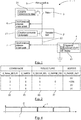
Fig. 4 ] est une représentation d'un signal de test du transistor du dispositif de commande, selon le mode de réalisation des figures précédentes.
- [
Fig. 1 ] presents a simplified functional diagram of a device for controlling an ultra-fast circuit breaker according to an embodiment of the invention; - [
Fig. 2 ] represents a truth table of the voltage measurement circuits implemented in the control device according to the embodiment of the [Fig. 1 ]; - [
Fig. 3 ] illustrates the electrical diagram of the control device according to the embodiment of the [Fig. 1 ], the ultra-fast circuit breaker not being shown, and - [
Fig. 4 ] is a representation of a test signal of the transistor of the control device, according to the embodiment of the previous figures.
Les disjoncteurs ultra rapides, lorsqu'ils sont mis en œuvre dans le domaine ferroviaire, permettent de protéger et d'isoler la section, ou sous station, de la ligne aérienne de contact (ligne d'alimentation au-dessus du matériel roulant, par exemple pour un tramway), ou de la ligne au sol de contact (ligne d'alimentation sous le matériel roulant, par exemple pour un métro) contre les défauts et les éventuelles surcharges. Ils peuvent, par exemple, être sécurisés par un verrouillage mécanique, afin de permettre une éventuelle action de maintenance sur la section électrique en toute sécurité. Enfin, ils sont aptes à communiquer avec les disjoncteurs des sous-stations adjacentes.Ultra-fast circuit breakers, when used in the railway sector, make it possible to protect and isolate the section, or sub-station, of the overhead contact line (supply line above the rolling stock, by example for a tram), or the ground contact line (supply line under rolling stock, for example for a metro) against faults and possible overloads. They can, for example, be secured by mechanical locking, in order to allow any maintenance action on the electrical section in complete safety. Finally, they are able to communicate with the circuit breakers of the adjacent substations.
De sorte à remplir sa fonction, le disjoncteur ultra rapide comporte un circuit interne de coupure comprenant une bobine électromagnétique de commande. Cette bobine présente un temps de démagnétisation de plusieurs millisecondes, généralement de l'ordre de 5 à 10 millisecondes. De cette manière, le disjoncteur ultra rapide est protégé contre les microcoupures qui pourraient avoir lieu au sein du circuit électrique dans lequel il est placé, et ne disjonctera pas à chaque microcoupure inférieure au temps de démagnétisation de la bobine.So as to fulfill its function, the ultra-fast circuit breaker includes an internal breaking circuit comprising an electromagnetic control coil. This coil has a demagnetization time of several milliseconds, generally of the order of 5 to 10 milliseconds. In this way, the ultra fast circuit breaker is protected against micro-breaks which could take place within the electrical circuit in which it is placed, and will not trip at each micro-break less than the demagnetization time of the coil.
Afin de commander un tel disjoncteur ultra rapide, et notamment de le faire commuter lorsqu'une défaillance est détectée dans le circuit électrique dans lequel il est situé, l'invention propose un dispositif de commande de structure nouvelle.In order to control such an ultra fast circuit breaker, and in particular to make it switch when a fault is detected in the electrical circuit in which it is located, the invention provides a device for controlling a new structure.
On présente maintenant, en relation avec les
Comme illustré en
Ainsi, le relais de pilotage 3 et le transistor de puissance 2 sont montés en série dans le circuit d'alimentation de la bobine de commande du disjoncteur ultra rapide 4, la bobine de commande étant destinée à fermer ou ouvrir le disjoncteur lorsqu'elle est alimentée ou non, respectivement.Thus, the
Selon un aspect d'un mode de réalisation, cette borne d'entrée du relais de pilotage peut par exemple comprendre un condensateur coudéAccording to one aspect of an embodiment, this input terminal of the control relay can for example comprise an angled capacitor
Dans ce mode de réalisation, les moyens d'alimentation électrique fournissent un courant continu.In this embodiment, the electrical supply means supply a direct current.
Le courant transitant dans le disjoncteur ultra-rapide peut varier de 0 A à 8 kA en nominal et peut tolérer des défauts jusqu'à 100 kA.The current flowing in the high-speed circuit breaker can vary from 0 A to 8 kA nominal and can tolerate faults up to 100 kA.
Selon un mode de réalisation, de sorte à protéger l'installation en cas, notamment, d'erreur de branchement (inversion des pôles par exemple), le dispositif de commande peut en outre comprendre au moins une diode de protection, par exemple une première diode 8 en série avec une diode Zener 9.According to one embodiment, so as to protect the installation in the event, in particular, of connection error (reversal of the poles for example), the control device can also comprise at least one protection diode, for example a
La mise en œuvre du relais de pilotage 3 et du transistor de puissance 2 permet d'obtenir un double niveau de sûreté de fonctionnement, sans mode commun, de sorte à pouvoir, par exemple en cas de détection d'une anomalie sur le circuit électrique, permettre le déclenchement de l'organe de coupure, à savoir le disjoncteur ultra rapide 4.The implementation of the
Le transistor de puissance 2 est, dans ce mode de réalisation, un transistor MOSFET de type n (présentant une grille, un drain et une source). On rappelle que lorsque la tension grille-source VGS est inférieure à la tension de seuil, on dit que le transistor est bloqué, il ne conduit pas. Dans le cas contraire, on dit qu'il est passant, et dans ce cas, il conduit le courant entre le drain et la source. Ainsi le transistor de puissance 2 peut commuter selon la tension appliquée entre la grille et la source.The
Pour répondre aux modes de défaillance (bloqué ouvert ou bloqué fermé) du transistor de puissance 2, le relais de pilotage 3 est disposé en série (pour le mode bloqué fermé) et dans le mode bloqué ouvert, le danger pour les personnes est nul car le disjoncteur ultra rapide 4 est bloqué ouvert.To respond to the failure modes (blocked open or blocked closed) of the
L'invention propose de vérifier en cours de fonctionnement que le transistor de puissance 2 et le relais de pilotage 3 ont les capacités de commuter.The invention proposes to verify during operation that the
Pour ce faire, le dispositif de commande ou de pilotage 1 comprend des moyens de contrôle en continu de l'état de fonctionnement du transistor de puissance 2, lesdits moyens de contrôle en continu comprenant un circuit de commande 21 apte à générer une impulsion électrique prédéterminée destinée à faire commuter ledit transistor de puissance 2.To do this, the control or piloting
Comme illustré en
Le circuit de commande 21 est configuré pour injecter un signal de test sur la grille du transistor de puissance 2.The
Le convertisseur de tension 211 est plus particulièrement programmé pour établir une séquence d'essais prédéterminée de sorte à déterminer le fonctionnement ou le non fonctionnement du transistor de puissance 2 en continu. Ceci permet de tester à tout moment l'état de fonctionnement du circuit de commande du disjoncteur.The
Le test est effectué par l'intermédiaire d'un programme exécuté par le convertisseur de tension 211. Ce test peut être déclenché périodiquement.The test is carried out by means of a program executed by the
De cette manière, un dysfonctionnement du transistor de puissance 2 (qui correspond au blocage du transistor en positon ouverte ou fermée) peut être détecté lorsque ce dernier ne commute pas en réponse à une impulsion électrique prédéterminée envoyée par le circuit de commande 2. Cette impulsion électrique correspond à une microcoupure de tension de durée comprise entre 0,1ms et 1ms.In this way, a malfunction of the power transistor 2 (which corresponds to the blocking of the transistor in open or closed position) can be detected when the latter does not switch in response to a predetermined electrical pulse sent by the
Il est à noter que, dans ce mode de réalisation, le transistor de puissance 2 a un temps de commutation de 100 ns.It should be noted that, in this embodiment, the
Dans le présent mode de réalisation, le signal de test illustré en
Dans le mode de réalisation décrit, cette période est de l'ordre du dixième de milliseconde.In the embodiment described, this period is of the order of a tenth of a millisecond.
Pour vérifier si la commutation du transistor de puissance 2 est effective en réponse à une impulsion électrique prédéterminée, les moyens de contrôle en continu comprennent en outre un circuit de mesure de la tension aux bornes du transistor de puissance 2.To check whether the switching of the
Le convertisseur de tension 211 détecte ainsi la tension aux bornes du transistor de puissance 2 par le biais d'un circuit de mesure de tension qui est monté en dérivation aux bornes du transistor de puissance 2 pour détecter un état de conduction ou de non conduction de celui-ci aux fins de réaliser un test de son bon fonctionnement.The
Ce circuit de mesure de la tension aux bornes du transistor de puissance 2 comprend une première portion 6 de circuit placée en amont du transistor de puissance 4 et une deuxième portion 7 de circuit placée en aval du transistor de puissance 4.This circuit for measuring the voltage across the
Comme illustré en
En effet, en générant des impulsions électriques, on incite le transistor de puissance 2 à commuter. Si la valeur de tension aux bornes du transistor de puissance 2 ne change pas alors il est déterminé que ce dernier est bloqué en position ouverte ou fermée. Dans le cas contraire, si la valeur de tension aux bornes du transistor de puissance 2 change, il est déterminé que ce dernier est en bon état de fonctionnement, et est apte à remplir son rôle de coupure de l'installation en cas de besoin.Indeed, by generating electrical pulses, the
De sorte à effectuer cette vérification, ce dispositif de commande 1 met en œuvre un procédé de test, également objet de l'invention.So as to carry out this verification, this
Ce procédé de test comprend les étapes suivantes :
- une étape de génération d'une impulsion électrique prédéterminée destinée à faire commuter le
transistor de puissance 2 en réponse à l'impulsion électrique prédéterminée ; - une étape de mesure de la tension en amont et en aval du
transistor de puissance 2 ; - une étape de comparaison entre la tension mesurée en amont et en aval du
transistor de puissance 2 en fonction de l'état dudittransistor de puissance 2, de sorte à contrôler le bon fonctionnement dutransistor de puissance 2.
- a step of generating a predetermined electrical pulse for switching the
power transistor 2 in response to the predetermined electrical pulse; - a step of measuring the voltage upstream and downstream of the
power transistor 2; - a step of comparing the voltage measured upstream and downstream of the
power transistor 2 as a function of the state of saidpower transistor 2, so as to check the correct operation of thepower transistor 2.
Comme décrit précédemment, l'étape de génération d'une impulsion électrique prédéterminée est mise en œuvre, selon les modes de réalisation, pendant une durée comprise entre 0,1 ms et 1 ms.As described above, the step of generating a predetermined electrical pulse is implemented, according to the embodiments, for a duration of between 0.1 ms and 1 ms.
En outre, de sorte à ce que le contrôle soit continu, et selon le mode de réalisation présenté, le procédé de test est répété périodiquement, la période étant de l'ordre du dixième de millisecondeIn addition, so that the control is continuous, and according to the embodiment presented, the test method is repeated periodically, the period being of the order of tenths of a millisecond.
De cette manière, la commutation du transistor de puissance 2 est testée à chaque période.In this way, the switching of the
A chaque période, correspondant à chaque itération du procédé, la tension en amont et en aval du transistor de puissance 2 est mesurée puis est comparée en fonction de l'état dudit transistor de puissance 2, de sorte à contrôler le bon fonctionnement du transistor de puissance 2.At each period, corresponding to each iteration of the process, the voltage upstream and downstream of the
On présente en
Il est à noter que cette borne de sortie 22 du transistor de puissance 2 est une sortie « tout ou rien », qui laisse donc passer, soit l'intégralité du courant, soit aucun courant, selon l'état de commutation du transistor.It should be noted that this
En outre, afin de protéger cette sortie 22 de pics de courant et de tension, notamment rencontrés lors d'ouvertures du disjoncteur ultra-rapide, un circuit de protection 23 est mis en œuvre à proximité de cette borne de sotie 22.In addition, in order to protect this
Un tel circuit de protection comprend, dans ce mode de réalisation, une pluralité de diodes « de roue libre » et d'un transistor MOSFET de type n.Such a protection circuit comprises, in this embodiment, a plurality of “freewheeling” diodes and an n-type MOSFET.
Par ailleurs, le transistor de puissance 2 et le relais de pilotage 3 sont binairement commandés en opposé. En d'autres termes, le relais de pilotage 3 est actif (fermé) avec une commande à 0 et inactif (ouvert) avec une commande à 1 tandis que le transistor de puissance est actif (fermé) avec une commande à 1 et inactif (ouvert) avec une commande à 0.Furthermore, the
Ceci permet de s'assurer que le disjoncteur ultra rapide puisse être ouvert lorsque le transistor de puissance 2 est défaillant (bloqué ouvert ou bloqué fermé).This ensures that the high-speed circuit breaker can be opened when the
Comme illustré en
Dans une deuxième situation, lorsque le relais de pilotage 3 est actif et que le transistor de puissance 2 est actif, les première 6 et deuxième 7 portions de circuit détectent une tension. La borne de sortie 22 du transistor de puissance 2 présente un courant positif.In a second situation, when the
Dans une troisième situation, lorsque le relais de pilotage 3 est inactif et que le transistor de puissance 2 est inactif, les première 6 et deuxième 7 portions de circuit ne détectent aucune tension. La borne de sortie 22 présente un courant nul.In a third situation, when the
Enfin, dans une quatrième situation, lorsque le relais de pilotage 3 est inactif et que le transistor de puissance est actif, la première portion 6 de circuit de mesure ne détecte aucune tension en amont du transistor de puissance 2 tandis qu'aucune tension n'est détectée en aval du transistor de puissance 2 par la deuxième portion 7 de circuit de mesure. La borne de sortie 22 du transistor de puissance 2 présente un courant nul.Finally, in a fourth situation, when the
Ainsi, lorsqu'une anomalie est détectée à l'étape de comparaison entre la tension mesurée en amont et en aval du transistor de puissance 2 (typiquement les première et quatrième situations), en fonction de l'état du transistor de puissance 2, cette anomalie est remontée par logiciel pour déclencher le « watchdog ». Cette information force l'ouverture du disjoncteur ultra rapide.Thus, when an anomaly is detected in the step of comparing the voltage measured upstream and downstream of the power transistor 2 (typically the first and fourth situations), depending on the state of the
Il est à noter que, selon un mode de réalisation, ce « watchdog » peut également se déclencher si aucune tension n'est détectée en amont et en aval.It should be noted that, according to one embodiment, this “watchdog” can also be triggered if no voltage is detected upstream and downstream.
Cette étape de coupure peut, selon le mode de réalisation présenté, apparaître au bout d'un nombre prédéterminé d'itérations.This cutting step can, depending on the embodiment presented, appear after a predetermined number of iterations.
En d'autres termes, avant d'ouvrir le disjoncteur ultra-rapide, le procédé de test peut être itéré une ou plusieurs fois, de sorte à s'assurer que l'anomalie est bien réelle, ceci afin d'éviter que l'ouverture du disjoncteur ultra-rapide ne soit faite par la transmission d'une anomalie inexistante. Cette pluralité d'itérations permet ainsi de s'assurer de la véracité de cette anomalie avec une fiabilité renforcée.In other words, before opening the high-speed circuit breaker, the test process can be iterated one or more times, so as to ensure that the anomaly is real, in order to prevent the the high-speed circuit breaker is not opened by the transmission of a non-existent anomaly. This plurality of iterations thus makes it possible to ensure the veracity of this anomaly with enhanced reliability.
Par exemple, on peut prévoir qu'au bout d'une dizaine d'itérations présentant une anomalie, le procédé comprend une étape de coupure de la tension sortant de la borne de sortie 22 du transistor de puissance 2.For example, it is possible to provide that after ten or so iterations presenting an anomaly, the method comprises a step of cutting the voltage leaving the
On peut également prévoir qu'au bout de cinq itérations, par exemple, présentant une anomalie, le procédé comprend l'étape de coupure de la tension sortant de la borne de sortie 22 du transistor de puissance 2.It is also possible to provide that after five iterations, for example, presenting an anomaly, the method comprises the step of cutting the voltage leaving the
Une telle temporisation permet notamment d'écarter un risque de mauvaise décision d'ouverture du disjoncteur ultra rapide.Such a delay makes it possible in particular to avoid a risk of poor decision to open the ultra-fast circuit breaker.
Selon un mode de réalisation particulier, le procédé peut comprendre en outre une étape de contrôle de l'état de fonctionnement du relais de pilotage 3.According to a particular embodiment, the method can also comprise a step of checking the operating state of the
Une telle étape de contrôle de l'état de fonctionnement du relais de pilotage 3 peut par exemple être mise en œuvre avant chaque redémarrage du réseau électrique, ou lors de phases de maintenance périodiques (mensuelle, annuelle).Such a step of checking the operating state of the
Cette étape de contrôle peut permettre également de déterminer s'il faut activer ou non le relais de pilotage, par le biais du circuit de commande du relais.This control step can also make it possible to determine whether or not to activate the piloting relay, by means of the relay control circuit.
La condition de fermeture du relais de pilotage peut comprendre une pluralité de conditions préalables tel que l'état « prêt » du relais de pilotage, l'absence de défaut détecté dans le réseau électrique et notamment au niveau du transistor.The closing condition of the control relay can include a plurality of preconditions such as the “ready” state of the control relay, the absence of a fault detected in the electrical network and in particular at the level of the transistor.
Il est à noter qu'en cas d'absence d'alimentation du relais de pilotage, le relais n'étant pas alimenté, le circuit est ouvert et le disjoncteur ultra rapide également.It should be noted that in the event of a lack of supply to the control relay, the relay not being supplied, the circuit is open and the ultra-fast circuit breaker also.
Les phases de maintenance périodique peuvent également comprendre des étapes de contrôle de commutations (ouverture et fermeture) du relais de pilotage 3 et du transistor de puissance 2.The periodic maintenance phases may also include steps for controlling switching (opening and closing) of the
Une telle phase de maintenance peut consister en un test comprenant les étapes suivantes :
- manœuvre d'ouverture (ou désactivation) et fermeture (ou activation) du relais de pilotage et/ou du transistor de puissance ;
- mesure du temps de réponse du relais de pilotage et/ou du transistor de puissance ;
- mesure du temps de réponse du réseau électrique en globalité.
- opening (or deactivation) and closing (or activation) operation of the control relay and / or the power transistor;
- measurement of the response time of the control relay and / or of the power transistor;
- measurement of the overall network response time.
Il est à noter que le procédé de test de dispositif de commande d'un organe de coupure objet de l'invention peut être adapté pour tout type de disjoncteur ultra-rapide.It should be noted that the test method for controlling a cut-off device which is the subject of the invention can be adapted for any type of ultra-fast circuit breaker.
Par exemple, on pourrait prévoir que le disjoncteur ultra-rapide soit un disjoncteur 24 V, 48 V voire 127 V.For example, one could provide that the ultra-fast circuit breaker is a 24 V, 48 V or even 127 V circuit breaker.
Claims (14)
caractérisé en ce qu'il comprend un relais de pilotage (3) dont la borne d'entrée est reliée à des moyens d'alimentation électrique (5) et la borne de sortie est reliée à un transistor de puissance (2), la borne de sortie (22) du transistor de puissance (2) étant reliée audit organe de coupure (4),
et en ce que le dispositif comprend en outre des moyens de contrôle en continu de l'état de fonctionnement dudit transistor de puissance (2), lesdits moyens de contrôle continu comprenant un circuit de commande (21) du transistor de puissance (2) apte à générer une impulsion électrique prédéterminée destinée à faire commuter ledit transistor de puissance (2), un dysfonctionnement dudit transistor de puissance (2) étant détecté lorsque ce dernier ne commute pas en réponse à ladite impulsion électrique prédéterminée.Control device (1) for a cut-off member of an electrical installation, such as an ultra-fast circuit breaker (4),
characterized in that it comprises a control relay (3), the input terminal of which is connected to electrical supply means (5) and the output terminal of which is connected to a power transistor (2), the terminal output (22) of the power transistor (2) being connected to said cut-off member (4),
and in that the device further comprises means for continuously monitoring the operating state of said power transistor (2), said continuous monitoring means comprising a control circuit (21) of the power transistor (2) capable generating a predetermined electrical pulse for switching said power transistor (2), a malfunction of said power transistor (2) being detected when the latter does not switch in response to said predetermined electrical pulse.
Applications Claiming Priority (2)
| Application Number | Priority Date | Filing Date | Title |
|---|---|---|---|
| FR1858440A FR3086062A1 (en) | 2018-09-18 | 2018-09-18 | DEVICE FOR CONTROLLING A CUT-OFF MEMBER OF AN ELECTRICAL INSTALLATION AND METHOD FOR TESTING SUCH A DEVICE |
| FR1901340A FR3086061B1 (en) | 2018-09-18 | 2019-02-11 | Device for controlling a switching device of an electrical installation and method for testing such a device |
Publications (2)
| Publication Number | Publication Date |
|---|---|
| EP3627164A1 true EP3627164A1 (en) | 2020-03-25 |
| EP3627164B1 EP3627164B1 (en) | 2023-08-09 |
Family
ID=67847661
Family Applications (1)
| Application Number | Title | Priority Date | Filing Date |
|---|---|---|---|
| EP19195694.5A Active EP3627164B1 (en) | 2018-09-18 | 2019-09-05 | System comprising a device for controlling a high-speed circuit breaker of an electrical installation and method for testing such a system |
Country Status (1)
| Country | Link |
|---|---|
| EP (1) | EP3627164B1 (en) |
Citations (9)
| Publication number | Priority date | Publication date | Assignee | Title |
|---|---|---|---|---|
| FR2489038A1 (en) * | 1980-08-21 | 1982-02-26 | Biegelmeier Gottfried | FAULT CURRENT CIRCUIT BREAKER |
| FR2500927A1 (en) * | 1981-02-27 | 1982-09-03 | Marchal Equip Auto | Air flowmeter protecting ventilator ballast transistor - has sensor which contains one heating resistor placed between two thermistors which are connected to comparator |
| FR2556904A1 (en) * | 1983-12-20 | 1985-06-21 | Ates Componenti Elettron | MONOLITHICALLY INTEGRAL INDUCTIVE LOAD SWITCHING CONTROL CIRCUIT COMPRISING A DARLINGTON FINAL FLOOR |
| FR2651915A1 (en) * | 1989-09-13 | 1991-03-15 | Merlin Gerin | ULTRA-FAST STATIC CIRCUIT BREAKER WITH GALVANIC ISOLATION. |
| US5629610A (en) * | 1994-05-06 | 1997-05-13 | Sgs-Thomson Microelectronics S.R.L. | Dual threshold current mode digital PWM controller |
| FR2843676A1 (en) * | 2002-06-25 | 2004-02-20 | Yazaki Corp | Lamp drive unit for motor vehicle, outputs control signal in order to supply electric power from supply line to lamp through relay contacts, when voltage applied to lamp is more than predetermined value |
| US20080007883A1 (en) * | 2006-05-15 | 2008-01-10 | Infineon Technologies Ag | Vehicle on-board electric power system |
| FR3028894A1 (en) * | 2014-11-26 | 2016-05-27 | Peugeot Citroen Automobiles Sa | DEVICE FOR CONTROLLING THE ELECTRIC POWER SUPPLY OF A STARTER SOLENOID |
| US20170110870A1 (en) * | 2014-06-23 | 2017-04-20 | Robert Bosch Gmbh | Method and device for current sensing of small currents |
-
2019
- 2019-09-05 EP EP19195694.5A patent/EP3627164B1/en active Active
Patent Citations (9)
| Publication number | Priority date | Publication date | Assignee | Title |
|---|---|---|---|---|
| FR2489038A1 (en) * | 1980-08-21 | 1982-02-26 | Biegelmeier Gottfried | FAULT CURRENT CIRCUIT BREAKER |
| FR2500927A1 (en) * | 1981-02-27 | 1982-09-03 | Marchal Equip Auto | Air flowmeter protecting ventilator ballast transistor - has sensor which contains one heating resistor placed between two thermistors which are connected to comparator |
| FR2556904A1 (en) * | 1983-12-20 | 1985-06-21 | Ates Componenti Elettron | MONOLITHICALLY INTEGRAL INDUCTIVE LOAD SWITCHING CONTROL CIRCUIT COMPRISING A DARLINGTON FINAL FLOOR |
| FR2651915A1 (en) * | 1989-09-13 | 1991-03-15 | Merlin Gerin | ULTRA-FAST STATIC CIRCUIT BREAKER WITH GALVANIC ISOLATION. |
| US5629610A (en) * | 1994-05-06 | 1997-05-13 | Sgs-Thomson Microelectronics S.R.L. | Dual threshold current mode digital PWM controller |
| FR2843676A1 (en) * | 2002-06-25 | 2004-02-20 | Yazaki Corp | Lamp drive unit for motor vehicle, outputs control signal in order to supply electric power from supply line to lamp through relay contacts, when voltage applied to lamp is more than predetermined value |
| US20080007883A1 (en) * | 2006-05-15 | 2008-01-10 | Infineon Technologies Ag | Vehicle on-board electric power system |
| US20170110870A1 (en) * | 2014-06-23 | 2017-04-20 | Robert Bosch Gmbh | Method and device for current sensing of small currents |
| FR3028894A1 (en) * | 2014-11-26 | 2016-05-27 | Peugeot Citroen Automobiles Sa | DEVICE FOR CONTROLLING THE ELECTRIC POWER SUPPLY OF A STARTER SOLENOID |
Also Published As
| Publication number | Publication date |
|---|---|
| EP3627164B1 (en) | 2023-08-09 |
Similar Documents
| Publication | Publication Date | Title |
|---|---|---|
| EP2053741B1 (en) | Self-protected static electric switching device | |
| EP3507877B1 (en) | Method for controlling an installation allowing dc current to be transmitted in a network while protecting said network from a short circuit fault | |
| FR2891093A1 (en) | ELECTRONIC TRIGGER WITH MONITORING MEANS, CIRCUIT BREAKER COMPRISING SUCH A TRIGGER AND SURVEILLANCE METHOD. | |
| FR2952470A1 (en) | CURRENT LIMITING CIRCUIT BREAKER, ELECTRICAL DISTRIBUTION DEVICE PROVIDED WITH SUCH LIMITER BREAKER, AND CURRENT LIMITATION METHOD | |
| EP3577672B1 (en) | High-voltage direct-current cutoff switch device | |
| FR3009624A1 (en) | INTEGRAL TEST OF ARC / PITCHES PHENOMENA DETECTOR | |
| EP1225673B1 (en) | Electrical power distribution device, installation comprising such a device and method for electrical protection | |
| CA2649225C (en) | Safety device for a semiconductor switch | |
| EP3033821A1 (en) | Remote protection and switching device for electrical systems | |
| EP3627164B1 (en) | System comprising a device for controlling a high-speed circuit breaker of an electrical installation and method for testing such a system | |
| FR3086061A1 (en) | Device for controlling a cut-off member of an electrical installation and method for testing such a device | |
| EP4016570B1 (en) | Electromechanical switching device for an electric power circuit | |
| EP4199284A1 (en) | Methods for detecting an electrical fault, associated electrical protection systems | |
| EP0720193A1 (en) | Electric control for opening and closing a switch or a circuit breaker | |
| EP3259815A1 (en) | System for selective protection of an electrical network and associated method of protection | |
| FR2870996A1 (en) | Electrical and electronic circuits protection device for motor vehicle, has disconnection units that cause breakdown of protection fuse if closed current traversing closed current circuit becomes abnormally high | |
| FR3048138A1 (en) | CIRCUIT BREAKER AND SYSTEM FOR PROTECTING AN ELECTRICITY NETWORK | |
| WO2020164945A1 (en) | Static dc current-limiting switching system | |
| FR2976414A1 (en) | Method for differential protection of long electrical link e.g. air-line, in high/very high voltage medium of three-phase network, involves measuring capacitive current of electrical link, and triggering relay during event of link defect | |
| EP1764892A1 (en) | Device for monitoring a fault current at the output of an energy source in a vehicle | |
| EP2693585B1 (en) | System for protecting a plurality of electrical outlets against short circuits, and electrical facility comprising such a protective system | |
| EP4139946B1 (en) | Circuit breaker with electronic trip control | |
| EP3297111B1 (en) | Device and method for monitoring the activity of processing units in an electric trip switch | |
| WO2023166263A1 (en) | System and method for protecting an electrical network | |
| EP3869659B1 (en) | Electrical supply system comprising a plurality of batteries |
Legal Events
| Date | Code | Title | Description |
|---|---|---|---|
| PUAI | Public reference made under article 153(3) epc to a published international application that has entered the european phase |
Free format text: ORIGINAL CODE: 0009012 |
|
| STAA | Information on the status of an ep patent application or granted ep patent |
Free format text: STATUS: THE APPLICATION HAS BEEN PUBLISHED |
|
| AK | Designated contracting states |
Kind code of ref document: A1 Designated state(s): AL AT BE BG CH CY CZ DE DK EE ES FI FR GB GR HR HU IE IS IT LI LT LU LV MC MK MT NL NO PL PT RO RS SE SI SK SM TR |
|
| AX | Request for extension of the european patent |
Extension state: BA ME |
|
| STAA | Information on the status of an ep patent application or granted ep patent |
Free format text: STATUS: REQUEST FOR EXAMINATION WAS MADE |
|
| 17P | Request for examination filed |
Effective date: 20200911 |
|
| RBV | Designated contracting states (corrected) |
Designated state(s): AL AT BE BG CH CY CZ DE DK EE ES FI FR GB GR HR HU IE IS IT LI LT LU LV MC MK MT NL NO PL PT RO RS SE SI SK SM TR |
|
| STAA | Information on the status of an ep patent application or granted ep patent |
Free format text: STATUS: EXAMINATION IS IN PROGRESS |
|
| 17Q | First examination report despatched |
Effective date: 20221108 |
|
| GRAP | Despatch of communication of intention to grant a patent |
Free format text: ORIGINAL CODE: EPIDOSNIGR1 |
|
| STAA | Information on the status of an ep patent application or granted ep patent |
Free format text: STATUS: GRANT OF PATENT IS INTENDED |
|
| INTG | Intention to grant announced |
Effective date: 20230331 |
|
| P01 | Opt-out of the competence of the unified patent court (upc) registered |
Effective date: 20230519 |
|
| GRAS | Grant fee paid |
Free format text: ORIGINAL CODE: EPIDOSNIGR3 |
|
| GRAA | (expected) grant |
Free format text: ORIGINAL CODE: 0009210 |
|
| STAA | Information on the status of an ep patent application or granted ep patent |
Free format text: STATUS: THE PATENT HAS BEEN GRANTED |
|
| AK | Designated contracting states |
Kind code of ref document: B1 Designated state(s): AL AT BE BG CH CY CZ DE DK EE ES FI FR GB GR HR HU IE IS IT LI LT LU LV MC MK MT NL NO PL PT RO RS SE SI SK SM TR |
|
| REG | Reference to a national code |
Ref country code: GB Ref legal event code: FG4D Free format text: NOT ENGLISH |
|
| REG | Reference to a national code |
Ref country code: CH Ref legal event code: EP |
|
| REG | Reference to a national code |
Ref country code: IE Ref legal event code: FG4D Free format text: LANGUAGE OF EP DOCUMENT: FRENCH |
|
| REG | Reference to a national code |
Ref country code: DE Ref legal event code: R096 Ref document number: 602019034430 Country of ref document: DE |
|
| REG | Reference to a national code |
Ref country code: LT Ref legal event code: MG9D |
|
| REG | Reference to a national code |
Ref country code: NL Ref legal event code: MP Effective date: 20230809 |
|
| REG | Reference to a national code |
Ref country code: AT Ref legal event code: MK05 Ref document number: 1598135 Country of ref document: AT Kind code of ref document: T Effective date: 20230809 |
|
| PG25 | Lapsed in a contracting state [announced via postgrant information from national office to epo] |
Ref country code: GR Free format text: LAPSE BECAUSE OF FAILURE TO SUBMIT A TRANSLATION OF THE DESCRIPTION OR TO PAY THE FEE WITHIN THE PRESCRIBED TIME-LIMIT Effective date: 20231110 |
|
| PGFP | Annual fee paid to national office [announced via postgrant information from national office to epo] |
Ref country code: GB Payment date: 20231129 Year of fee payment: 5 |
|
| PG25 | Lapsed in a contracting state [announced via postgrant information from national office to epo] |
Ref country code: IS Free format text: LAPSE BECAUSE OF FAILURE TO SUBMIT A TRANSLATION OF THE DESCRIPTION OR TO PAY THE FEE WITHIN THE PRESCRIBED TIME-LIMIT Effective date: 20231209 |
|
| PG25 | Lapsed in a contracting state [announced via postgrant information from national office to epo] |
Ref country code: SE Free format text: LAPSE BECAUSE OF FAILURE TO SUBMIT A TRANSLATION OF THE DESCRIPTION OR TO PAY THE FEE WITHIN THE PRESCRIBED TIME-LIMIT Effective date: 20230809 Ref country code: RS Free format text: LAPSE BECAUSE OF FAILURE TO SUBMIT A TRANSLATION OF THE DESCRIPTION OR TO PAY THE FEE WITHIN THE PRESCRIBED TIME-LIMIT Effective date: 20230809 Ref country code: PT Free format text: LAPSE BECAUSE OF FAILURE TO SUBMIT A TRANSLATION OF THE DESCRIPTION OR TO PAY THE FEE WITHIN THE PRESCRIBED TIME-LIMIT Effective date: 20231211 Ref country code: NO Free format text: LAPSE BECAUSE OF FAILURE TO SUBMIT A TRANSLATION OF THE DESCRIPTION OR TO PAY THE FEE WITHIN THE PRESCRIBED TIME-LIMIT Effective date: 20231109 Ref country code: NL Free format text: LAPSE BECAUSE OF FAILURE TO SUBMIT A TRANSLATION OF THE DESCRIPTION OR TO PAY THE FEE WITHIN THE PRESCRIBED TIME-LIMIT Effective date: 20230809 Ref country code: LV Free format text: LAPSE BECAUSE OF FAILURE TO SUBMIT A TRANSLATION OF THE DESCRIPTION OR TO PAY THE FEE WITHIN THE PRESCRIBED TIME-LIMIT Effective date: 20230809 Ref country code: LT Free format text: LAPSE BECAUSE OF FAILURE TO SUBMIT A TRANSLATION OF THE DESCRIPTION OR TO PAY THE FEE WITHIN THE PRESCRIBED TIME-LIMIT Effective date: 20230809 Ref country code: IS Free format text: LAPSE BECAUSE OF FAILURE TO SUBMIT A TRANSLATION OF THE DESCRIPTION OR TO PAY THE FEE WITHIN THE PRESCRIBED TIME-LIMIT Effective date: 20231209 Ref country code: HR Free format text: LAPSE BECAUSE OF FAILURE TO SUBMIT A TRANSLATION OF THE DESCRIPTION OR TO PAY THE FEE WITHIN THE PRESCRIBED TIME-LIMIT Effective date: 20230809 Ref country code: GR Free format text: LAPSE BECAUSE OF FAILURE TO SUBMIT A TRANSLATION OF THE DESCRIPTION OR TO PAY THE FEE WITHIN THE PRESCRIBED TIME-LIMIT Effective date: 20231110 Ref country code: FI Free format text: LAPSE BECAUSE OF FAILURE TO SUBMIT A TRANSLATION OF THE DESCRIPTION OR TO PAY THE FEE WITHIN THE PRESCRIBED TIME-LIMIT Effective date: 20230809 Ref country code: AT Free format text: LAPSE BECAUSE OF FAILURE TO SUBMIT A TRANSLATION OF THE DESCRIPTION OR TO PAY THE FEE WITHIN THE PRESCRIBED TIME-LIMIT Effective date: 20230809 |
|
| PGFP | Annual fee paid to national office [announced via postgrant information from national office to epo] |
Ref country code: FR Payment date: 20231013 Year of fee payment: 5 Ref country code: DE Payment date: 20231026 Year of fee payment: 5 |
|
| PG25 | Lapsed in a contracting state [announced via postgrant information from national office to epo] |
Ref country code: PL Free format text: LAPSE BECAUSE OF FAILURE TO SUBMIT A TRANSLATION OF THE DESCRIPTION OR TO PAY THE FEE WITHIN THE PRESCRIBED TIME-LIMIT Effective date: 20230809 |
|
| PGFP | Annual fee paid to national office [announced via postgrant information from national office to epo] |
Ref country code: BE Payment date: 20231016 Year of fee payment: 5 |