EP3627043A1 - Hohlprofilelement zur verwendung als quer- und/oder längsreling eines möbels - Google Patents
Hohlprofilelement zur verwendung als quer- und/oder längsreling eines möbels Download PDFInfo
- Publication number
- EP3627043A1 EP3627043A1 EP19194832.2A EP19194832A EP3627043A1 EP 3627043 A1 EP3627043 A1 EP 3627043A1 EP 19194832 A EP19194832 A EP 19194832A EP 3627043 A1 EP3627043 A1 EP 3627043A1
- Authority
- EP
- European Patent Office
- Prior art keywords
- hollow profile
- profile element
- elements
- cavity
- wall
- Prior art date
- Legal status (The legal status is an assumption and is not a legal conclusion. Google has not performed a legal analysis and makes no representation as to the accuracy of the status listed.)
- Granted
Links
Images

Classifications
-
- F—MECHANICAL ENGINEERING; LIGHTING; HEATING; WEAPONS; BLASTING
- F21—LIGHTING
- F21V—FUNCTIONAL FEATURES OR DETAILS OF LIGHTING DEVICES OR SYSTEMS THEREOF; STRUCTURAL COMBINATIONS OF LIGHTING DEVICES WITH OTHER ARTICLES, NOT OTHERWISE PROVIDED FOR
- F21V33/00—Structural combinations of lighting devices with other articles, not otherwise provided for
- F21V33/0004—Personal or domestic articles
- F21V33/0012—Furniture
-
- F—MECHANICAL ENGINEERING; LIGHTING; HEATING; WEAPONS; BLASTING
- F21—LIGHTING
- F21S—NON-PORTABLE LIGHTING DEVICES; SYSTEMS THEREOF; VEHICLE LIGHTING DEVICES SPECIALLY ADAPTED FOR VEHICLE EXTERIORS
- F21S4/00—Lighting devices or systems using a string or strip of light sources
- F21S4/20—Lighting devices or systems using a string or strip of light sources with light sources held by or within elongate supports
-
- A—HUMAN NECESSITIES
- A47—FURNITURE; DOMESTIC ARTICLES OR APPLIANCES; COFFEE MILLS; SPICE MILLS; SUCTION CLEANERS IN GENERAL
- A47B—TABLES; DESKS; OFFICE FURNITURE; CABINETS; DRAWERS; GENERAL DETAILS OF FURNITURE
- A47B2220/00—General furniture construction, e.g. fittings
- A47B2220/0075—Lighting
- A47B2220/0077—Lighting for furniture, e.g. cupboards and racks
-
- F—MECHANICAL ENGINEERING; LIGHTING; HEATING; WEAPONS; BLASTING
- F21—LIGHTING
- F21W—INDEXING SCHEME ASSOCIATED WITH SUBCLASSES F21K, F21L, F21S and F21V, RELATING TO USES OR APPLICATIONS OF LIGHTING DEVICES OR SYSTEMS
- F21W2131/00—Use or application of lighting devices or systems not provided for in codes F21W2102/00-F21W2121/00
- F21W2131/30—Lighting for domestic or personal use
- F21W2131/301—Lighting for domestic or personal use for furniture
-
- F—MECHANICAL ENGINEERING; LIGHTING; HEATING; WEAPONS; BLASTING
- F21—LIGHTING
- F21Y—INDEXING SCHEME ASSOCIATED WITH SUBCLASSES F21K, F21L, F21S and F21V, RELATING TO THE FORM OR THE KIND OF THE LIGHT SOURCES OR OF THE COLOUR OF THE LIGHT EMITTED
- F21Y2103/00—Elongate light sources, e.g. fluorescent tubes
- F21Y2103/10—Elongate light sources, e.g. fluorescent tubes comprising a linear array of point-like light-generating elements
-
- F—MECHANICAL ENGINEERING; LIGHTING; HEATING; WEAPONS; BLASTING
- F21—LIGHTING
- F21Y—INDEXING SCHEME ASSOCIATED WITH SUBCLASSES F21K, F21L, F21S and F21V, RELATING TO THE FORM OR THE KIND OF THE LIGHT SOURCES OR OF THE COLOUR OF THE LIGHT EMITTED
- F21Y2115/00—Light-generating elements of semiconductor light sources
- F21Y2115/10—Light-emitting diodes [LED]
Definitions
- the invention relates to a hollow profile element for use as a transverse and / or longitudinal rail of a piece of furniture, a railing of a drawer and a piece of furniture.
- Lighting devices for drawers are already known.
- a drawer frame comprises a translucent wall element, lighting means and a frame body, the frame body being designed to arrange a guide system for the drawer and the lighting means are present on the drawer frame below the wall element, between the wall element and the frame body.
- the illuminants illuminate the wall element in such a way that the wall element laterally radiates the light radiated into the wall element inwards or outwards, so that, for example, an interior of the drawer can be illuminated.
- the invention has for its object to provide an improved hollow profile element for use as cross rails and / or longitudinal rails of a piece of furniture, in particular to provide a hollow profile element which enables improved attachment of lamps to a drawer frame and / or improved lighting of the drawer frame.
- the invention relates to a hollow profile element for use as a transverse and / or longitudinal rail of a piece of furniture, the hollow profile element having a cavity, the cavity extending into a longitudinal extension of the hollow profile element, the hollow profile element having openings on opposite and spaced end faces, the Openings of the end faces are present as openings of the cavity, the cavity being enclosed by a lower, an upper and two lateral wall elements of the hollow profile element, the lower, the upper and the two lateral wall elements extending in the longitudinal extent of the hollow profile element, the hollow profile element has a recess on the lower wall element, the recess, in particular the lower wall element, being formed from opposite and spaced-apart side elements and a support element, the side elements and the support elements nt extend in the longitudinal extent of the hollow profile element, the support element connecting the side elements to one another, the support element is recessed on the hollow profile element, the support element having translucent light transmission elements, so that, starting from the cavity of the hollow profile element, visible light in particular can emerge from the hollow profile
- the hollow profile element preferably comprises a single cavity.
- the side wall elements are advantageously spaced apart from one another and formed opposite one another.
- the upper wall element and the lower wall element are also spaced apart and are located opposite one another.
- the side wall element connects the upper wall element to the lower wall element, for example.
- the recess is, for example, U-shaped, for example in the form of a U-shaped groove.
- the lower wall element is completely formed by the recess.
- the hollow profile element advantageously comprises a single recess.
- the cutout preferably extends, in particular the side element and the support element of the cutout extend over more than half of a length of the hollow profile element in the longitudinal extent of the hollow profile element.
- the cutout advantageously extends over at least 50%, at least 75%, at least 80%, at least 90% or at least 95% of the length of the hollow profile element in the longitudinal extent of the hollow profile element.
- the recess extends, in particular the side element and the support element extend over an entire length of the hollow profile element in the longitudinal extent of the hollow profile element.
- the recess is formed in the arranged state of the hollow profile element a drawer frame, in particular on a drawer, to arrange a frame wall of the drawer frame, for example between the side elements.
- the support element is present adjacent to the frame wall, in particular on an upper side of the frame wall.
- the hollow profile element advantageously extends in its longitudinal extent in a length between 200 mm and 1400 mm, e.g. between 220mm and 1300mm, especially between 250mm and 1150mm.
- the hollow profile element is, for example, 200 mm, 220 mm, 250 mm, 300 mm, 400 mm, 1000 mm, 1150 mm, 1200 mm, 1300 mm or 1400 mm in length.
- the hollow profile element is for example between 6mm and 20mm, between 6mm and 18mm, between 6mm and 16mm, between 6mm and 12mm or between 6mm and 10mm wide.
- the width of the hollow profile element is, for example, 6mm, 6.5mm, 7mm, 7.5mm, 8.5mm, 9mm, 9.5mm, 10mm, 11mm, 12mm, 16mm, 18mm or 20mm, in particular 8mm.
- the width of the hollow profile element advantageously extends from an outside of a first side wall element to an outside of the further side wall element.
- the outer sides of the side wall elements are, for example, on the side wall element facing away from the cavity.
- the side wall elements include, for example, inner sides, which each form a boundary of the cavity.
- the inside of a wall element is advantageously spaced apart and present opposite the outside of the wall element.
- the inside and the outside of the wall element are preferably spaced apart from one another by a wall thickness of the wall element.
- the hollow profile element is for example between 5mm and 30mm, between 10mm and 25mm, between 12mm and 25mm, between 12mm and 20mm, between 14mm and 20mm or between 16mm and 18mm high.
- the height of the hollow profile element is, for example, 5mm, 10mm, 11mm, 12mm, 14mm, 18mm, 20mm, 25mm or 30mm, in particular 16mm.
- a wall thickness of the upper wall element, a side wall element, the lower wall element, the side elements and / or the support element is, for example, between 0.3 mm and 3 mm.
- the wall thickness is, for example, between 0.5 mm and 2.5 mm, between 0.6 mm and 2 mm, between 0.8 mm and 1.5 mm.
- the upper wall element, a side wall element, the lower wall element, the side element and / or the support element has, for example, a wall thickness of 0.3 mm, 0.4 mm, 0.6 mm, 0.7 mm, 0.8 mm, 0.9 mm, 1 mm, 1.2mm, 1.4mm, 1.6mm, 2mm especially 0.5mm.
- a length of the cavity advantageously extends over a full length of the hollow profile element.
- the length of the cavity corresponds, for example, to 50%, 60%, 70%, 80% or 90% of the length of the hollow profile element.
- the cavity extends for example over a width between 5 mm and 19 mm, between 5 mm and 14 mm, between 5 mm and 12 mm or between 5 mm and 10 mm.
- the width of the cavity is, for example, 5mm, 5.5mm, 6mm, 6.5mm, 7.5mm, 8mm, 8.5mm, 9mm, 9.5mm, 10mm, 12mm, 14mm or 19mm, in particular 7mm.
- the cavity extends, for example, over a height between 6 mm and 25 mm, between 6 mm and 20 mm or between 8 mm and 14 mm.
- the height of the cavity is, for example, 6mm, 7mm, 8mm, 9mm, 10mm, 12mm, 13mm, 14mm, 20mm or 25mm, especially 11mm.
- a ratio of the height to the width of the cavity is, for example, in a range between 2 to 1.2, between 1.8 to 1.2, between 1.8 to 1.3, between 1.8 to 1.4 or between 1.7 to 1.4, especially between 1.6 to 1.5.
- the ratio of the height to the width of the cavity is, for example, 1.2, 1.3, 1.4, 1.5, 1.55, 1.56, 1.58, 1.6, 1.7, 1.8 or 2, especially 1.57.
- a light bar be present in the cavity.
- the light bar is available, for example, as a light band.
- the light bar is an LED light bar, e.g. formed as an LED band.
- the frame wall and / or a drawer interior can be illuminated by the light strip, in particular in the case of a light-conducting frame wall.
- a mounting element is designed rail-like or clip-like, so that the light bar can be inserted into the mounting element.
- the mounting element is designed as a rail or clip.
- the mounting element is designed such that the light bar can be clamped or clipped onto the mounting element.
- the mounting element comprises an adhesive element, so that the light bar can be glued to the mounting element.
- the mounting element is present in a heat-conducting manner.
- the mounting element is made of metal, e.g. made of copper, sheet metal or aluminum.
- the cavity is advantageously free of material except for the mounting elements and / or the light bar, e.g. as a material-free hollow volume.
- the hollow profile element be designed as a continuous casting element.
- the side element of the cutout as a component of a side wall element is present.
- a side element and a wall element are formed in one piece.
- the hollow profile element is preferably present over at least 20%, at least 50% or at least 60% of its length along a circumference around the longitudinal extent, in particular completely closed.
- the hollow profile element is designed as a folded and / or folded element.
- the hollow profile element is made from a single bent and / or folded piece of metal, e.g. Sheet metal, especially strip steel, is formed.
- the hollow profile element is preferably brought into the final shape during production from a coherent flat material by reshaping, for example cold reshaping.
- the hollow profile element can be produced comparatively inexpensively. Ends of the flat material formed as a hollow profile element are connected to one another, for example. The ends of the formed flat material are, for example, welded to one another, glued or riveted or textured.
- a side element of the recess is connected to a side wall element via a bending section.
- the side wall element merges into the side element via the bending section.
- the side element of the recess is bent or folded over the bending section so far towards the side wall element that the side element and the side wall element are approximately parallel to one another.
- the upper wall element, the side Wall elements, the side elements and the support element are formed in one piece.
- a side element and a side wall element enclose a bending angle in a range between 45 degrees and 180 degrees.
- the hollow profile element is made of plastic and / or metal.
- the light transmission elements are present as through openings.
- the light transmission elements are designed as cylindrical, oval, rectangular and / or round holes.
- the light transmission elements are punched out of the remaining material of the hollow profile element.
- the support element e.g. in the form of cylindrical, oval, rectangular and / or round holes and that light transmission elements are inserted into the holes.
- the light transmission elements are designed in the form of color filters, e.g. as colored elements, e.g. as colored glass or plastic elements.
- the frame wall and / or the interior of the drawer can be illuminated in different colors, in particular in sections, when the hollow profile element is in the arranged state.
- the support element of the recess is only translucent in sections due to the light transmission elements, in particular for visible light. It is also conceivable that the support element of the recess is translucent through the light passage elements in the longitudinal extension of the hollow profile element, in particular for visible light.
- the light transmission elements are connected to one another.
- the light transmission elements are spaced apart from one another on the support element.
- the light transmission elements are preferably spaced apart from one another by a distance of between 10 mm and 30 mm.
- a distance between the light transmission elements, in particular in the direction of the hollow profile element longitudinal extension, is e.g. 10mm, 15mm, 25mm or 30mm, especially 20mm.
- An advantageous modification of the invention forms a railing of a drawer comprising a hollow profile element according to one of the preceding variants.
- a further advantageous embodiment of the invention is a piece of furniture with a rail as described above, the hollow profile element of the rail with the lower wall element being present placed on a frame wall of a frame of the piece of furniture, in particular a drawer.
- the hollow profile element of the railing is advantageously clamped onto and / or clipped onto the frame wall.
- the support element and / or the side elements in the attached state on the frame wall are in direct contact with the frame wall.
- the side elements of the hollow profile element preferably encompass the frame wall in the arranged state.
- the hollow profile element advantageously completely surrounds the upper side of the frame wall.
- the hollow profile element in the arranged state encloses the upper side of the frame wall with the side elements and the support element.
- the frame wall is, for example, transparent, for example made of glass or plastic. It is also conceivable for the frame wall to be light-guiding in sections.
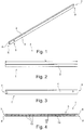
- Figure 1 shows a hollow profile element 1 according to the invention, comprising an upper wall element 2, a first lateral wall element 3, a second lateral wall element 4, and a lower wall element 5.
- a recess 8, 9 can be formed on a side wall element 3, 4 and / or on the lower wall element 5.
- the upper wall element 2 extends in a longitudinal extension of the hollow profile element 1 completely over a length L of the hollow profile element 1 ( Figures 2 to 4 ).
- the hollow profile element 1 also extends over a width B and a height H ( Figure 5 ).
- the lower wall element 5 comprises a recess 10 which is formed, for example, by a first side element 11, a second side element 12 and a support element 13.
- Light transmission elements in the form of openings 15 are formed on the recess 10 ( Figures 3 , 5 ).
- the openings 15 are formed in the longitudinal extent of the hollow profile element 1 at a distance D from each other.
- the hollow profile element 1 also comprises a cavity 14 which is delimited, for example, by the upper wall element 2, the side wall elements 3, 4 and the lower wall element 5. At the ends 6, 7 of the hollow profile element 1, the cavity 14 is advantageously open.
- the upper wall element 2, the side wall elements 3, 4, the side elements 11, 12 and the support element 13 are advantageously formed in one piece.
- the hollow profile element 1 is preferably formed from a folded or bent flat material 16. End sections 17, 18 of the flat material 16 are advantageously permanently connected to one another. For example, the end sections 17, 18 are welded along a contact area 19, on which the end sections 17, 18 abut, for example.
- the upper wall element 2, the side wall elements 3, 4 have the Side elements 11, 12 and / or the support element 13 have the same wall thickness d.
- the cavity 14 has a height h and a width b.
- the width b of the cavity 14 extends, for example, between inner surfaces 20, 21 of the side wall elements 3, 4.
- the height h of the cavity 14 extends, for example, from an inner surface 22 of the upper wall element 2 to an inner surface 23 of the support element 13.
- a mounting element 27 and / or a light strip 28 is present in the cavity 14, for example.
- the mounting element 27 is advantageously fastened to the hollow profile element 1.
- the light bar 28 is held in the cavity 14 by the mounting element 27.
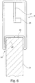
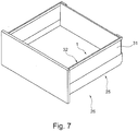
- the hollow profile element 1 is advantageously arranged adjacent to the frame wall 31 on a frame wall 31 of a frame 25 of a drawer 26 with an outer side 24 of the support element 13 ( Figures 6 , 7 ).
- the hollow profile element 1 advantageously forms a railing 32 of the drawer 26.
- the outside 24 of the support element 13 rests on an upper side 29 of the frame wall 31.
- the hollow profile element 1 preferably encloses with its recess 10, in particular the side elements 11, 12 and the support element 13, an upper region 30 of the frame wall 31 in the arranged state on the frame wall 31.
- the hollow profile element 1 is clamped on the frame wall 31 in the arranged state.
- the hollow profile element 1 and the frame wall 31 are positively connected to one another in the arranged state.
Landscapes
- Engineering & Computer Science (AREA)
- General Engineering & Computer Science (AREA)
- Health & Medical Sciences (AREA)
- Public Health (AREA)
- Securing Of Glass Panes Or The Like (AREA)
- Arrangement Of Elements, Cooling, Sealing, Or The Like Of Lighting Devices (AREA)
Abstract
Description
- Die Erfindung betrifft ein Hohlprofilelement zur Verwendung als Quer- und/oder Längsreling eines Möbels, eine Reling einer Schublade, sowie ein Möbel.
- Beleuchtungsvorrichtungen für Schubladen sind bereits bekannt.
- Bei einer bekannten Beleuchtungsvorrichtung umfasst eine Schubladenzarge ein lichtdurchlässiges Wandelement, Leuchtmittel und einen Zargenkörper, wobei der Zargenkörper zur Anordnung eines Führungssystems der Schublade ausgebildet ist und die Leuchtmittel an der Schubladenzarge unterhalb des Wandelements, zwischen Wandelement und Zargenkörper, vorhanden sind. Dabei beleuchten die Leuchtmittel das Wandelement derart, dass das Wandelement das in das Wandelement eingestrahlte Licht seitlich nach Innen oder Außen abstrahlt, wodurch beispielsweise ein Innenraum der Schublade beleuchtbar ist.
- Durch die vorteilhafte Anordnung der Leuchtmittel am Zargenkörper ist eine elektrische Kontaktierung und damit Stromversorgung der Leuchtmittel vergleichsweise einfach realisierbar.
- Der Erfindung liegt die Aufgabe zugrunde, ein verbessertes Hohlprofilelement zur Verwendung als Querreling und/oder Längsreling eines Möbels bereitzustellen, insbesondere ein Hohlprofilelement bereitzustellen, welches eine verbesserte Anbringung von Leuchtmitteln an einer Schubladenzarge und/oder eine verbesserte Beleuchtung der Schubladenzarge ermöglicht.
- Diese Aufgabe wird durch die Merkmale des Anspruchs 1, des Anspruchs 10, sowie des Anspruchs 11 gelöst.
- In den abhängigen Ansprüchen sind vorteilhafte und zweckmäßige Weiterbildungen der Erfindung genannt.
- Die Erfindung betrifft ein Hohlprofilelement zur Verwendung als Quer- und/oder Längsreling eines Möbels, wobei das Hohlprofilelement einen Hohlraum aufweist, wobei der Hohlraum sich in eine Längserstreckung des Hohlprofilelements erstreckt, wobei das Hohlprofilelement an sich gegenüberliegenden und voneinander beabstandeten Stirnseiten Öffnungen aufweist, wobei die Öffnungen der Stirnseiten als Öffnungen des Hohlraums vorhanden sind, wobei der Hohlraum durch ein unteres, ein oberes und zwei seitliche Wandelemente des Hohlprofilelements umschlossen vorhanden ist, wobei das untere, das obere und die zwei seitlichen Wandelemente sich in Längserstreckung des Hohlprofilelements erstrecken, wobei das Hohlprofilelement am unteren Wandelement eine Aussparung aufweist, wobei die Aussparung, insbesondere das untere Wandelement, aus sich gegenüberliegenden und voneinander beabstandeten Seitenelementen und einem Auflageelement ausgebildet ist, wobei die Seitenelemente und das Auflageelement sich in Längserstreckung des Hohlprofilelements erstrecken, wobei das Auflageelement die Seitenelemente miteinander verbindet, wobei das Auflageelement vertieft am Hohlprofilelement vorhanden ist, wobei das Auflageelement lichtdurchlässige Lichtdurchlasselemente aufweist, sodass ausgehend vom Hohlraum des Hohlprofilelements insbesondere sichtbares Licht durch die Lichtdurchlasselemente aus dem Hohlprofilelement austreten kann. Durch das erfindungsgemäße Hohlprofilelement ist eine Anbringung von Leuchtmitteln an einer Schubladenzarge und/oder eine verbesserte Beleuchtung der Schubladenzarge ermöglicht.
- Bevorzugterweise umfasst das Hohlprofilelement einen einzigen Hohlraum. Vorteilhafterweise sind die seitlichen Wandelemente voneinander beabstandet und sich gegenüberliegend ausgebildet. Das obere Wandelement und das untere Wandelement sind ebenfalls voneinander beabstandet und sich gegenüberliegend vorhanden. Das seitliche Wandelement verbindet beispielsweise jeweils das obere Wandelement mit dem unteren Wandelement.
- Die Aussparung ist beispielsweise U-förmig ausgebildet, z.B. in Form einer U-förmigen Nut. Beispielsweise ist das untere Wandelement vollständig durch die Aussparung gebildet. Vorteilhafterweise umfasst das Hohlprofilelement eine einzige Aussparung. Bevorzugterweise erstreckt sich die Aussparung, insbesondere erstrecken sich die Seitenelement und das Auflageelement der Aussparung, über mehr als eine Hälfte einer Länge des Hohlprofilelements in Längserstreckung des Hohlprofilelements. Vorteilhafterweise erstreckt sich die Aussparung über mindestens 50%, mindestens 75%, mindestens 80%, mindestens 90% oder mindestens 95% der Länge des Hohlprofilelements in Längserstreckung des Hohlprofilelements. Beispielsweise erstreckt sich die Aussparung, insbesondere erstrecken sich die Seitenelement und das Auflageelement, über eine gesamte Länge des Hohlprofilelements in Längserstreckung des Hohlprofilelements. Die Aussparung ist beispielsweise dazu ausgebildet im angeordneten Zustand des Hohlprofilelements an einer Schubladenzarge, insbesondere an einer Schublade, eine Zargenwand der Schubladenzarge anzuordnen, beispielsweise zwischen den Seitenelementen aufzunehmen. Beispielsweise ist im angeordneten Zustand des Hohlprofilelements an der Zargenwand das Auflageelement anliegend an der Zargenwand vorhanden, insbesondere an einer oberen Seite der Zargenwand.
- Vorteilhafterweise erstreckt sich das Hohlprofilelement in seiner Längserstreckung in einer Länge zwischen 200mm und 1400mm, z.B. zwischen 220mm und 1300mm, insbesondere zwischen 250mm und 1150mm. Das Hohlprofilelement ist in Längserstreckung gesehen beispielsweise 200mm, 220mm, 250mm, 300mm, 400mm, 1000mm, 1150mm, 1200mm, 1300mm oder 1400mm lang.
- Das Hohlprofilelement ist zum Beispiel zwischen 6mm und 20mm, zwischen 6mm und 18mm, zwischen 6mm und 16mm, zwischen 6mm und 12mm oder zwischen 6mm und 10mm breit. Die Breite des Hohlprofilelements ist beispielsweise 6mm, 6,5mm, 7mm, 7,5mm, 8,5mm, 9mm, 9,5mm, 10mm, 11mm, 12mm, 16mm, 18mm oder 20mm, insbesondere 8mm. Die Breite des Hohlprofilelements erstreckt sich vorteilhafterweise von einer Außenseite eines ersten seitlichen Wandelements bis zu einer Außenseite des weiteren seitlichen Wandelements. Die Außenseiten der seitlichen Wandelemente sind beispielswiese vom Hohlraum abgewandt am seitlichen Wandelement vorhanden. Die seitlichen Wandelemente umfassen zum Beispiel Innenseiten, welche jeweils eine Begrenzung des Hohlraums bilden. Die Innenseite eines Wandelements ist vorteilhafterweise beabstandet und gegenüberliegend zur Außenseite des Wandelements vorhanden. Die Innenseite und die Außenseite des Wandelements sind bevorzugterweise über eine Wandstärke des Wandelements zueinander beabstandet.
- Das Hohlprofilelement ist beispielsweise zwischen 5mm und 30mm, zwischen 10mm und 25mm, zwischen 12mm und 25mm, zwischen 12mm und 20mm, zwischen 14mm und 20mm oder zwischen 16mm und 18mm hoch. Die Höhe des Hohlprofilelements ist zum Beispiel 5mm, 10mm, 11mm, 12mm, 14mm, 18mm, 20mm, 25mm oder 30mm, insbesondere 16mm.
- Eine Wandstärke des oberen Wandelements, eines seitlichen Wandelements, des unteren Wandelements, der Seitenelemente und/oder des Auflagenelements ist beispielsweise zwischen 0,3mm und 3mm groß. Die Wandstärke ist beispielsweise zwischen 0,5mm und 2,5mm, zwischen 0,6mm und 2mm, zwischen 0,8mm und 1,5mm. Das obere Wandelement, ein seitliches Wandelement, das unteren Wandelements, das Seitenelement und/oder das Auflagenelement besitzt beispielsweise eine Wandstärke von 0,3mm, 0,4mm, 0,6mm, 0,7mm, 0,8mm, 0,9mm, 1mm, 1,2mm, 1,4mm, 1,6mm, 2mm insbesondere von 0,5mm.
- Eine Länge des Hohlraums erstreckt sich vorteilhafterweise über eine vollständige Länge des Hohlprofilelements. Die Länge des Hohlraums entspricht beispielsweise 50%, 60%, 70%, 80% oder 90% der Länge des Hohlprofilelements. Der Hohlraum erstreckt sich beispielsweise über eine Breite zwischen 5 mm und 19mm, zwischen 5mm und 14mm, zwischen 5mm und 12mm oder zwischen 5mm und 10mm. Die Breite des Hohlraums ist beispielsweise 5mm, 5,5mm, 6mm, 6,5mm, 7,5mm, 8mm, 8,5mm, 9mm, 9,5mm, 10mm, 12mm, 14mm oder 19mm, insbesondere 7mm. Der Hohlraum erstreckt sich beispielsweise über eine Höhe zwischen 6 mm und 25mm, zwischen 6mm und 20mm oder zwischen 8mm und 14mm. Die Höhe des Hohlraums ist zum Beispiel 6mm, 7mm, 8mm, 9mm, 10mm, 12mm, 13mm, 14mm, 20mm oder 25mm, insbesondere 11mm. Ein Verhältnis Höhe zu Breite des Hohlraums ist beispielsweise in einem Bereich zwischen 2 zu 1,2, zwischen 1,8 zu 1,2, zwischen 1,8 zu 1,3, zwischen 1,8 zu 1,4 oder zwischen 1,7 zu 1,4, insbesondere zwischen 1,6 zu 1,5. Das Verhältnis Höhe zu Breite des Hohlraums ist zum Beispiel 1,2, 1,3, 1,4, 1,5, 1,55, 1,56, 1,58, 1,6, 1,7, 1,8 oder 2, insbesondere 1,57.
- Weiter wird vorgeschlagen, dass im Hohlraum eine Lichtleiste vorhanden ist. Die Lichtleiste ist beispielsweise als ein Lichtband vorhanden. Zum Beispiel ist die Lichtleiste als eine LED-Lichtleiste, z.B. als ein LED-Band ausgebildet. Durch die Lichtleiste ist die Zargenwand und/oder ein Schubladeninnenraum beleuchtbar, insbesondere bei einer lichtleitenden Zargenwand.
- Auch erweist es sich von Vorteil, dass im Hohlraum Montageelemente zur Anbringung der Lichtleiste ausgebildet sind. Beispielsweise ist ein Montageelement schienenartig oder klammerartig ausgebildet, sodass die Lichtleiste in das Montageelement einschiebbar ist. Beispielsweise ist das Montageelement als Schiene oder Klammer ausgebildet. Beispielsweise ist das Montageelement derart ausgebildet, dass die Lichtleiste an das Montageelement klemmbar oder klippsbar ist. Vorstellbar ist auch, dass das Montageelement ein Klebeorgan umfasst, sodass die Lichtleiste an das Montagelement anklebbar ist. Denkbar ist auch, dass das Montageelement wärmeleitend vorhanden ist. Beispielsweise ist das Montageelement aus Metall, z.B. aus Kupfer, einem Blech oder Aluminium ausgebildet. Hierdurch ist im angeordneten Zustand der Lichtleiste am Hohlprofilelement ein Wärmeabtransport von Wärme der Lichtleiste verbessert.
- Der Hohlraum ist vorteilhafterweise bis auf die Montageelemente und/oder die Lichtleiste materialfrei vorhanden, z.B. als ein materialfreies Hohlvolumen.
- Auch wird vorgeschlagen, dass das Hohlprofilelement als ein Stranggusselement ausgebildet ist. Insbesondere in diesem Fall ist es vorteilhaft, dass das Seitenelement der Aussparung als ein Bestandteil eines seitlichen Wandelements vorhanden ist. Beispielsweise sind insbesondere in diesem Fall ein Seitenelement und ein Wandelement einstückig ausgebildet. Hierdurch ist das Hohlprofilelement vergleichsweise kostengünstig herstellbar.
- Bevorzugterweise ist das Hohlprofilelement über mindestens 20%, mindestens 50% oder mindestens 60% seiner Länge entlang eines Umfangs um die Längserstreckung herum, insbesondere vollständig geschlossen vorhanden.
- In einer vorteilhaften Ausbildung ist das Hohlprofilelement als ein abgekantetes und/oder umgekantetes Element ausgebildet. Vorteilhafterweise ist das Hohlprofilelement aus einem einzigen umgebogenen und/oder abgekantetem Stück Metall, z.B. Blech, insbesondere Bandstahl, ausgebildet. Vorzugsweise ist das Hohlprofilelement bei der Herstellung aus einem zusammenhängenden Flachmaterial durch Umformen wie zum Beispiel Kaltumformen in die Endform gebracht. Hierdurch ist das Hohlprofilelement vergleichsweise kostengünstig herstellbar. Enden des als Hohlprofilelement umgeformten Flachmaterials sind beispielsweise miteinander verbunden. Die Enden des umgeformten Flachmaterials sind zum Beispiel miteinander verschweißt, geklebt oder genietet bzw. getoxt.
- Beispielsweise ist ein Seitenelement der Aussparung über einen Umbiegeabschnitt mit einem seitlichen Wandelement verbunden. Zum Beispiel geht das seitliche Wandelement über den Umbiegeabschnitt in das Seitenelement über. Beispielsweise ist das Seitenelement der Aussparung über den Umbiegeabschnitt so weit zum seitlichen Wandelement hin umgebogen oder umgekantet vorhanden, dass das Seitenelement und das seitliche Wandelement in etwa parallel zueinander verlaufend vorhanden sind. Vorteilhafterweise sind das obere Wandelement, die seitlichen Wandelemente, die Seitenelemente, sowie das Auflageelement einstückig ausgebildet. Beispielsweise schließen ein Seitenelement und ein seitliches Wandelement einen Biegewinkel in einem Bereich zwischen 45 Winkelgrad und 180 Winkelgrad ein.
- Überdies ist es von Vorteil, dass das Hohlprofilelement aus Kunststoff und/oder Metall ausgebildet ist.
- Außerdem erweist es sich von Vorteil, dass die Lichtdurchlasselemente als Durchgangsöffnungen vorhanden sind. Beispielsweise sind die Lichtdurchlasselemente als zylinderförmige, ovale, rechteckige und/oder runde Löcher ausgebildet. Z.B. sind die Lichtdurchlasselemente aus dem verbleibenden Material des Hohlprofilelements ausgestanzt vorhanden.
- Denkbar ist weiter, dass am Auflageelement Durchgangsöffnungen vorhanden sind, z.B. in Form von zylinderförmigen, ovalen, rechteckigen und/oder runden Löchern und, dass in die Löcher Lichtdurchlasselemente eingesetzt sind. Beispielsweise sind die Lichtdurchlasselemente in Form von Farbfiltern ausgebildet, z.B. als farbige Elemente, z.B. als farbige Glas- oder Kunststoffelemente. Hierdurch ist die Zargenwand und/oder der Schubladeninnenraum im angeordneten Zustand des Hohlprofilelements insbesondere abschnittsweise verschiedenfarbig beleuchtbar.
- Überdies ist es von Vorteil, dass das Auflageelement der Aussparung durch die Lichtdurchlasselemente ausschließlich abschnittsweise für insbesondere sichtbares Licht lichtdurchlässig vorhanden ist. Denkbar ist auch, dass das Auflageelement der Aussparung durch die Lichtdurchlasselemente in Längserstreckung des Hohlprofilelements durchgehend für insbesondere sichtbares Licht lichtdurchlässig vorhanden ist.
- Beispielsweise sind die Lichtdurchlasselemente miteinander verbunden.
- Bei einer vorteilhaften Variante des Hohlprofilelements sind die Lichtdurchlasselemente voneinander beabstandet am Auflageelement vorhanden. Bevorzugterweise sind die Lichtdurchlasselemente über einen Abstand zwischen 10mm und 30mm zueinander beabstandet. Ein Abstand der Lichtdurchlasselemente, insbesondere in Richtung Hohlprofilelement-Längserstreckung gesehen beträgt z.B. 10mm, 15mm, 25mm oder 30mm, insbesondere 20mm.
- Eine vorteilhafte Modifikation der Erfindung bildet eine Reling einer Schublade umfassend ein Hohlprofilelement nach einer der vorangegangenen Varianten.
- Eine weitere vorteilhafte Ausgestaltung der Erfindung ist ein Möbel mit einer Reling wie vorangegangen beschrieben, wobei das Hohlprofilelement der Reling mit dem unteren Wandelement auf eine Zargenwand einer Zarge des Möbels, insbesondere einer Schublade, aufgesetzt vorhanden ist.
- Vorteilhafterweise ist das Hohlprofilelement der Reling auf die Zargenwand aufgeklemmt und/oder aufgeklippst vorhanden. Beispielsweise ist das Auflageelement und/oder die Seitenelemente im aufgesetzten Zustand an der Zargenwand in einem unmittelbaren Kontakt mit der Zargenwand. Bevorzugterweise umgreifen die Seitenelemente des Hohlprofilelements die Zargenwand im angeordneten Zustand. Vorteilhafterweise umschließt das Hohlprofilelement im angeordneten Zustand die obere Seite der Zargenwand insbesondere vollständig. Beispielsweise umschließt das Hohlprofilelement im angeordneten Zustand die obere Seite der Zargenwand mit den Seitenelementen und dem Auflageelement.
- Die Zargenwand ist beispielsweise transparent ausgebildet, z.B. aus Glas oder Kunststoff. Denkbar ist auch, dass die Zargenwand abschnittsweise lichtleitend ausgebildet ist.
- Ein Ausführungsbeispiel ist anhand der nachstehenden schematischen Zeichnungen unter Angabe weiterer Einzelheiten und Vorteile näher erläutert.
- Es zeigen:
- Figur 1
- eine perspektivische Ansicht eines erfindungsgemäßen Hohlprofilelements von schräg seitlich vorne oben,
- Figur 2
- eine Draufsicht auf das Hohlprofilelement gemäß
Figur 1 , - Figur 3
- eine seitliche Ansicht des Hohlprofilelements gemäß
Figur 1 , - Figur 4
- eine Unteransicht des Hohlprofilelements gemäß
Figur 1 , - Figur 5
- eine Schnittansicht des Hohlprofilelements gemäß
Figur 1 quer zu einer Längserstreckung des Hohlprofilelements, - Figur 6
- eine Schnittansicht eines an eine Zargenwand angeordneten Hohlprofilelements durch das Hohlprofilelement und die Zargenwand und
- Figur 7
- eine perspektivische Ansicht von schräg seitlich vorne oben auf eine Schublade mit einem Hohlprofilelement.
-
Figur 1 zeigt ein erfindungsgemäßes Hohlprofilelement 1, umfassend ein oberes Wandelement 2, ein erstes seitliches Wandelement 3, ein zweites seitliches Wandelement 4, sowie ein unteres Wandelement 5. An Enden 6, 7 des Hohlprofilelements 1 kann an einem seitlichen Wandelement 3, 4 und/oder am unteren Wandelement 5 eine Ausnehmung 8, 9 ausgebildet sein. - Vorteilhafterweise erstreckt sich das obere Wandelement 2 in einer Längserstreckung des Hohlprofilelements 1 vollständig über eine Länge L des Hohlprofilelements 1 (
Figuren 2 bis 4 ). Das Hohlprofilelement 1 erstreckt sich weiterhin über eine Breite B und eine Höhe H (Figur 5 ). - Das untere Wandelement 5 umfasst eine Aussparung 10, welche z.B. durch ein erstes Seitenelement 11, ein zweites Seitenelement 12 und ein Auflageelement 13 gebildet ist. An der Aussparung 10 sind Lichtdurchlasselemente in Form von Öffnungen 15 ausgebildet (
Figuren 3 ,5 ). Die Öffnungen 15 sind in Längserstreckung des Hohlprofilelements 1 über eine Distanz D zueinander beabstandet ausgebildet. - Das Hohlprofilelement 1 umfasst außerdem einen Hohlraum 14, welcher beispielsweise vom oberen Wandelement 2, den seitlichen Wandelementen 3, 4 und dem unteren Wandelement 5 begrenzt ist. An den Enden 6, 7 des Hohlprofilelements 1 ist der Hohlraum 14 vorteilhafterweise offen vorhanden.
- Das obere Wandelement 2, die seitlichen Wandelemente 3, 4, die Seitenelemente 11, 12, sowie das Auflageelement 13 sind vorteilhafterweise einstückig ausgebildet. Bevorzugterweise ist das Hohlprofilelement 1 aus einem umgekanteten oder umgebogenen Flachmaterial 16 ausgebildet. Endabschnitte 17, 18 des Flachmaterials 16 sind vorteilhafterweise unlösbar miteinander verbunden. Beispielsweise sind die Endabschnitte 17, 18 entlang eines Anlagebereichs 19, an welchem die Endabschnitte 17, 18 z.B. aneinander anliegen, verschweißt. Beispielsweise besitzen das obere Wandelement 2, die seitlichen Wandelemente 3, 4, die Seitenelemente 11, 12 und/oder das Auflageelement 13 eine gleiche Wandstärke d.
- Der Hohlraum 14 weist eine Höhe h und eine Breite b auf. Die Breite b des Hohlraums 14 erstreckt sich beispielsweise zwischen Innenflächen 20, 21 der seitlichen Wandelemente 3, 4. Die Höhe h des Hohlraums 14 erstreckt sich zum Beispiel von einer Innenfläche 22 des oberen Wandelements 2 bis zu einer Innenfläche 23 des Auflageelements 13.
- Im Hohlraum 14 ist beispielsweise ein Montageelement 27 und/oder eine Lichtleiste 28 vorhanden. Vorteilhafterweise ist das Montageelement 27 am Hohlprofilelement 1 befestigt. Beispielsweise ist die Lichtleiste 28 durch das Montageelement 27 im Hohlraum 14 gehalten.
- Das Hohlprofilelement 1 ist im angeordneten Zustand an einer Zargenwand 31 einer Zarge 25 einer Schublade 26 mit einer Außenseite 24 des Auflageelements 13 vorteilhafterweise anliegend an der Zargenwand 31 angeordnet (
Figuren 6 ,7 ). Vorteilhafterweise bildet in diesem Fall das Hohlprofilelement 1 eine Reling 32 der Schublade 26. Beispielsweise liegt im angeordneten Zustand an der Zargenwand 31 die Außenseite 24 des Auflageelements 13 auf einer Oberseite 29 der Zargenwand 31 auf. - Bevorzugterweise umschließt das Hohlprofilelement 1 mit seiner Aussparung 10, insbesondere mit den Seitenelementen 11, 12 und dem Auflageelement 13 einen oberen Bereich 30 der Zargenwand 31 im angeordneten Zustand an der Zargenwand 31. Beispielsweise ist das Hohlprofilelement 1 im angeordneten Zustand an die Zargenwand 31 angeklemmt. Zum Beispiel sind das Hohlprofilelement 1 und die Zargenwand 31 im angeordneten Zustand formschlüssig miteinander verbunden.
-
- 1
- Hohlprofilelement
- 2 - 5
- Wandelement
- 6, 7
- Ende
- 8, 9
- Ausnehmung
- 10
- Aussparung
- 11, 12
- Seitenelement
- 13
- Auflageelement
- 14
- Hohlraum
- 15
- Lichtdurchlasselement
- 16
- Flachmaterial
- 17, 18
- Endabschnitt
- 19
- Anlagebereich
- 20 - 23
- Innenfläche
- 24
- Außenseite
- 25
- Zarge
- 26
- Schublade
- 27
- Montageelement
- 28
- Lichtleiste
- 29
- Oberseite
- 30
- Bereich
- 31
- Zargenwand
- 32
- Reling
Claims (11)
- Hohlprofilelement (1) zur Verwendung als Quer- und/oder Längsreling eines Möbels, wobei das Hohlprofilelement (1) einen Hohlraum (14) aufweist, wobei der Hohlraum (14) sich in eine Längserstreckung des Hohlprofilelements (1) erstreckt, wobei das Hohlprofilelement (1) an sich gegenüberliegenden und voneinander beabstandeten Stirnseiten Öffnungen aufweist, wobei die Öffnungen der Stirnseiten als Öffnungen des Hohlraums (14) vorhanden sind, wobei der Hohlraum (14) durch ein unteres, ein oberes und zwei seitliche Wandelemente (2 - 5) des Hohlprofilelements (1) umschlossen vorhanden ist, wobei das untere, das obere und die zwei seitlichen Wandelemente (2 - 5) sich in Längserstreckung des Hohlprofilelements (1) erstrecken, wobei das Hohlprofilelement (1) am unteren Wandelement (5) eine Aussparung (10) aufweist, wobei die Aussparung (10) aus sich gegenüberliegenden und voneinander beabstandeten Seitenelementen (11, 12) und einem Auflageelement (13) ausgebildet ist, wobei die Seitenelemente (11, 12) und das Auflageelement (13) sich in Längserstreckung des Hohlprofilelements (1) erstrecken, wobei das Auflageelement (13) die Seitenelemente (11, 12) miteinander verbindet, wobei das Auflageelement (13) vertieft am Hohlprofilelement (1) vorhanden ist, wobei das Auflageelement (13) lichtdurchlässige Lichtdurchlasselemente (15) aufweist, sodass ausgehend vom Hohlraum (14) des Hohlprofilelements (1) Licht durch die Lichtdurchlasselemente (15) aus dem Hohlprofilelement (1) austreten kann.
- Hohlprofilelement (1) zur Verwendung als Quer- und/oder Längsreling nach dem Anspruch 1, dadurch gekennzeichnet, dass im Hohlraum (14) eine Lichtleiste (28) vorhanden ist.
- Hohlprofilelement (1) zur Verwendung als Quer- und/oder Längsreling nach einem der vorangegangenen Ansprüche, dadurch gekennzeichnet, dass im Hohlraum (14) Montageelemente (27) zur Anbringung einer Lichtleiste (28) ausgebildet sind.
- Hohlprofilelement (1) zur Verwendung als Quer- und/oder Längsreling nach einem der vorangegangenen Ansprüche, dadurch gekennzeichnet, dass das Hohlprofilelement (1) als ein Stranggusselement ausgebildet ist.
- Hohlprofilelement (1) zur Verwendung als Quer- und/oder Längsreling nach einem der vorangegangenen Ansprüche, dadurch gekennzeichnet, dass das Hohlprofilelement (1) als ein abgekantetes und/oder umgekantetes Element (16) ausgebildet ist.
- Hohlprofilelement (1) zur Verwendung als Quer- und/oder Längsreling nach einem der vorangegangenen Ansprüche, dadurch gekennzeichnet, dass das Hohlprofilelement (1) aus Kunststoff und/oder Metall ausgebildet ist.
- Hohlprofilelement (1) zur Verwendung als Quer- und/oder Längsreling nach einem der vorangegangenen Ansprüche, dadurch gekennzeichnet, dass die Lichtdurchlasselemente (15) als Durchgangsöffnungen vorhanden sind.
- Hohlprofilelement (1) zur Verwendung als Quer- und/oder Längsreling nach einem der vorangegangenen Ansprüche, dadurch gekennzeichnet, dass das Auflageelement (14) der Aussparung (10) durch die Lichtdurchlasselemente (15) ausschließlich abschnittsweise für insbesondere sichtbares Licht lichtdurchlässig vorhanden ist.
- Hohlprofilelement (1) zur Verwendung als Quer- und/oder Längsreling nach einem der vorangegangenen Ansprüche, dadurch gekennzeichnet, dass die Lichtdurchlasselemente (15) voneinander beabstandet am Auflageelement (13) vorhanden sind.
- Reling (32) einer Schublade (26) umfassend ein Hohlprofilelement (1) nach einem der vorangegangenen Ansprüche.
- Möbel mit einer Reling (32) nach Anspruch 10, wobei das Hohlprofilelement (1) der Reling (32) mit dem unteren Wandelement (5) auf eine Zargenwand (31) einer Zarge (25) des Möbels, insbesondere einer Schublade (26), aufgesetzt vorhanden ist.
Applications Claiming Priority (1)
| Application Number | Priority Date | Filing Date | Title |
|---|---|---|---|
| DE202018105329.9U DE202018105329U1 (de) | 2018-09-18 | 2018-09-18 | Hohlprofilelement zur Verwendung als Quer- und/oder Längsreling eines Möbels |
Publications (2)
| Publication Number | Publication Date |
|---|---|
| EP3627043A1 true EP3627043A1 (de) | 2020-03-25 |
| EP3627043B1 EP3627043B1 (de) | 2021-10-27 |
Family
ID=67840945
Family Applications (1)
| Application Number | Title | Priority Date | Filing Date |
|---|---|---|---|
| EP19194832.2A Active EP3627043B1 (de) | 2018-09-18 | 2019-09-02 | Hohlprofilelement zur verwendung als quer- und/oder längsreling eines möbels |
Country Status (2)
| Country | Link |
|---|---|
| EP (1) | EP3627043B1 (de) |
| DE (1) | DE202018105329U1 (de) |
Families Citing this family (1)
| Publication number | Priority date | Publication date | Assignee | Title |
|---|---|---|---|---|
| DE102023130082A1 (de) | 2023-10-31 | 2025-04-30 | Paul Hettich Gmbh & Co. Kg | Schubkasten |
Citations (4)
| Publication number | Priority date | Publication date | Assignee | Title |
|---|---|---|---|---|
| DE202005008286U1 (de) * | 2005-05-27 | 2006-10-05 | Paul Hettich Gmbh & Co. Kg | Schubkasten |
| DE202010012629U1 (de) * | 2010-09-22 | 2010-11-18 | Heim, Meinolf | Lichtleiste für Möbel, insbesondere Vitrinen |
| WO2012022009A1 (zh) * | 2010-08-18 | 2012-02-23 | 世塑有限公司 | 装有光源组件的抽屉结构 |
| DE202012011498U1 (de) * | 2012-11-30 | 2013-04-23 | Benjamin Berndt | LED Profil Glasboden |
Family Cites Families (4)
| Publication number | Priority date | Publication date | Assignee | Title |
|---|---|---|---|---|
| DE202008000195U1 (de) * | 2008-01-05 | 2008-04-17 | Häcker Küchen GmbH & Co. KG | Küchenmöbel mit Schublade und Beleuchtung |
| DE202010000997U1 (de) * | 2010-01-14 | 2011-05-26 | Grass Gmbh | Vorrichtung zur Beleuchtung einer Umgebung und/oder eines Innenraums eines beweglichen Möbelteils |
| DE202010001914U1 (de) * | 2010-02-05 | 2010-08-12 | Dieter Höltkemeyer Möbelfabrik GmbH & Co. KG | Möbelbauteil, insbesondere Möbelboden, und Möbelstück mit Möbelbauteil |
| DE202012101627U1 (de) * | 2012-05-03 | 2012-06-06 | L&S Deutschland Gmbh | Schranktür mit Licht-Griffhohle |
-
2018
- 2018-09-18 DE DE202018105329.9U patent/DE202018105329U1/de not_active Expired - Lifetime
-
2019
- 2019-09-02 EP EP19194832.2A patent/EP3627043B1/de active Active
Patent Citations (4)
| Publication number | Priority date | Publication date | Assignee | Title |
|---|---|---|---|---|
| DE202005008286U1 (de) * | 2005-05-27 | 2006-10-05 | Paul Hettich Gmbh & Co. Kg | Schubkasten |
| WO2012022009A1 (zh) * | 2010-08-18 | 2012-02-23 | 世塑有限公司 | 装有光源组件的抽屉结构 |
| DE202010012629U1 (de) * | 2010-09-22 | 2010-11-18 | Heim, Meinolf | Lichtleiste für Möbel, insbesondere Vitrinen |
| DE202012011498U1 (de) * | 2012-11-30 | 2013-04-23 | Benjamin Berndt | LED Profil Glasboden |
Also Published As
| Publication number | Publication date |
|---|---|
| EP3627043B1 (de) | 2021-10-27 |
| DE202018105329U1 (de) | 2019-12-19 |
Similar Documents
| Publication | Publication Date | Title |
|---|---|---|
| DE3540002A1 (de) | Foerderer mit einem mehrteiligen traeger | |
| DE4428357A1 (de) | Kittlos gesockelte Halogenglühlampe | |
| EP3556261A1 (de) | Draht-etage für einen verkaufstisch oder ein regalsystem | |
| EP3627043B1 (de) | Hohlprofilelement zur verwendung als quer- und/oder längsreling eines möbels | |
| DE102018104552B4 (de) | Verfahren zur Herstellung einer Dachreling, Strangpressprofil hierfür und Dachreling für ein Fahrzeug | |
| EP2760090B1 (de) | Befestigungssystem und Einbausatz für die Montage eines Montagestegs in einem Schaltschrank | |
| DE102007059171A1 (de) | Glaskantenbeleuchtung | |
| EP3009041B1 (de) | Wandbauteil, schublade mit einem solchen wandbauteil und möbel | |
| EP0787909A1 (de) | Klemmvorrichtung an teleskopisch zusammengesetzten Profilrohren | |
| EP4177519B1 (de) | Leuchte mit halteklammer | |
| DE19912078C2 (de) | Dachreling für Fahrzeuge | |
| CH620817A5 (en) | Connection of a shelf to a vertical support element in shelf units | |
| EP3379900B1 (de) | Kochfeld | |
| WO1994021970A1 (de) | Standkonsole für heizkörper | |
| DE19822349A1 (de) | Ausziehvorrichtung für Hochschränke | |
| EP4562340B1 (de) | Eckumlenkungselement für ein led-leuchtband und zugehörige leuchtanordnung | |
| EP3112784B1 (de) | Haushaltsgeräte-bauteil mit einem coextrudierten dekorteil | |
| DE102014106539B4 (de) | Traverse für einen Schrank | |
| DE102013213789A1 (de) | Leuchteinrichtung | |
| DE29901397U1 (de) | Längliche, im Querschnittsprofil linsenartige Pendel- oder Anbauleuchte | |
| DE20104933U1 (de) | Schienenmontagesystem | |
| DE4423037A1 (de) | Halteklammer für ein elektronisches Vorschaltgerät | |
| AT3321U1 (de) | Tankplatte für einen tank eines extrusionswerkzeuges | |
| DE102014200625A1 (de) | Dachrinnensystem | |
| DE102004003871C5 (de) | Leuchtstofflampe |
Legal Events
| Date | Code | Title | Description |
|---|---|---|---|
| PUAI | Public reference made under article 153(3) epc to a published international application that has entered the european phase |
Free format text: ORIGINAL CODE: 0009012 |
|
| STAA | Information on the status of an ep patent application or granted ep patent |
Free format text: STATUS: THE APPLICATION HAS BEEN PUBLISHED |
|
| AK | Designated contracting states |
Kind code of ref document: A1 Designated state(s): AL AT BE BG CH CY CZ DE DK EE ES FI FR GB GR HR HU IE IS IT LI LT LU LV MC MK MT NL NO PL PT RO RS SE SI SK SM TR |
|
| AX | Request for extension of the european patent |
Extension state: BA ME |
|
| STAA | Information on the status of an ep patent application or granted ep patent |
Free format text: STATUS: REQUEST FOR EXAMINATION WAS MADE |
|
| 17P | Request for examination filed |
Effective date: 20200921 |
|
| RBV | Designated contracting states (corrected) |
Designated state(s): AL AT BE BG CH CY CZ DE DK EE ES FI FR GB GR HR HU IE IS IT LI LT LU LV MC MK MT NL NO PL PT RO RS SE SI SK SM TR |
|
| GRAP | Despatch of communication of intention to grant a patent |
Free format text: ORIGINAL CODE: EPIDOSNIGR1 |
|
| STAA | Information on the status of an ep patent application or granted ep patent |
Free format text: STATUS: GRANT OF PATENT IS INTENDED |
|
| INTG | Intention to grant announced |
Effective date: 20210409 |
|
| GRAS | Grant fee paid |
Free format text: ORIGINAL CODE: EPIDOSNIGR3 |
|
| GRAA | (expected) grant |
Free format text: ORIGINAL CODE: 0009210 |
|
| STAA | Information on the status of an ep patent application or granted ep patent |
Free format text: STATUS: THE PATENT HAS BEEN GRANTED |
|
| AK | Designated contracting states |
Kind code of ref document: B1 Designated state(s): AL AT BE BG CH CY CZ DE DK EE ES FI FR GB GR HR HU IE IS IT LI LT LU LV MC MK MT NL NO PL PT RO RS SE SI SK SM TR |
|
| REG | Reference to a national code |
Ref country code: GB Ref legal event code: FG4D Free format text: NOT ENGLISH |
|
| REG | Reference to a national code |
Ref country code: CH Ref legal event code: EP |
|
| REG | Reference to a national code |
Ref country code: AT Ref legal event code: REF Ref document number: 1442107 Country of ref document: AT Kind code of ref document: T Effective date: 20211115 |
|
| REG | Reference to a national code |
Ref country code: DE Ref legal event code: R096 Ref document number: 502019002594 Country of ref document: DE |
|
| REG | Reference to a national code |
Ref country code: IE Ref legal event code: FG4D Free format text: LANGUAGE OF EP DOCUMENT: GERMAN |
|
| REG | Reference to a national code |
Ref country code: LT Ref legal event code: MG9D |
|
| REG | Reference to a national code |
Ref country code: NL Ref legal event code: MP Effective date: 20211027 |
|
| PG25 | Lapsed in a contracting state [announced via postgrant information from national office to epo] |
Ref country code: RS Free format text: LAPSE BECAUSE OF FAILURE TO SUBMIT A TRANSLATION OF THE DESCRIPTION OR TO PAY THE FEE WITHIN THE PRESCRIBED TIME-LIMIT Effective date: 20211027 Ref country code: LT Free format text: LAPSE BECAUSE OF FAILURE TO SUBMIT A TRANSLATION OF THE DESCRIPTION OR TO PAY THE FEE WITHIN THE PRESCRIBED TIME-LIMIT Effective date: 20211027 Ref country code: FI Free format text: LAPSE BECAUSE OF FAILURE TO SUBMIT A TRANSLATION OF THE DESCRIPTION OR TO PAY THE FEE WITHIN THE PRESCRIBED TIME-LIMIT Effective date: 20211027 Ref country code: BG Free format text: LAPSE BECAUSE OF FAILURE TO SUBMIT A TRANSLATION OF THE DESCRIPTION OR TO PAY THE FEE WITHIN THE PRESCRIBED TIME-LIMIT Effective date: 20220127 |
|
| PG25 | Lapsed in a contracting state [announced via postgrant information from national office to epo] |
Ref country code: IS Free format text: LAPSE BECAUSE OF FAILURE TO SUBMIT A TRANSLATION OF THE DESCRIPTION OR TO PAY THE FEE WITHIN THE PRESCRIBED TIME-LIMIT Effective date: 20220227 Ref country code: SE Free format text: LAPSE BECAUSE OF FAILURE TO SUBMIT A TRANSLATION OF THE DESCRIPTION OR TO PAY THE FEE WITHIN THE PRESCRIBED TIME-LIMIT Effective date: 20211027 Ref country code: PT Free format text: LAPSE BECAUSE OF FAILURE TO SUBMIT A TRANSLATION OF THE DESCRIPTION OR TO PAY THE FEE WITHIN THE PRESCRIBED TIME-LIMIT Effective date: 20220228 Ref country code: PL Free format text: LAPSE BECAUSE OF FAILURE TO SUBMIT A TRANSLATION OF THE DESCRIPTION OR TO PAY THE FEE WITHIN THE PRESCRIBED TIME-LIMIT Effective date: 20211027 Ref country code: NO Free format text: LAPSE BECAUSE OF FAILURE TO SUBMIT A TRANSLATION OF THE DESCRIPTION OR TO PAY THE FEE WITHIN THE PRESCRIBED TIME-LIMIT Effective date: 20220127 Ref country code: NL Free format text: LAPSE BECAUSE OF FAILURE TO SUBMIT A TRANSLATION OF THE DESCRIPTION OR TO PAY THE FEE WITHIN THE PRESCRIBED TIME-LIMIT Effective date: 20211027 Ref country code: LV Free format text: LAPSE BECAUSE OF FAILURE TO SUBMIT A TRANSLATION OF THE DESCRIPTION OR TO PAY THE FEE WITHIN THE PRESCRIBED TIME-LIMIT Effective date: 20211027 Ref country code: HR Free format text: LAPSE BECAUSE OF FAILURE TO SUBMIT A TRANSLATION OF THE DESCRIPTION OR TO PAY THE FEE WITHIN THE PRESCRIBED TIME-LIMIT Effective date: 20211027 Ref country code: GR Free format text: LAPSE BECAUSE OF FAILURE TO SUBMIT A TRANSLATION OF THE DESCRIPTION OR TO PAY THE FEE WITHIN THE PRESCRIBED TIME-LIMIT Effective date: 20220128 Ref country code: ES Free format text: LAPSE BECAUSE OF FAILURE TO SUBMIT A TRANSLATION OF THE DESCRIPTION OR TO PAY THE FEE WITHIN THE PRESCRIBED TIME-LIMIT Effective date: 20211027 |
|
| REG | Reference to a national code |
Ref country code: DE Ref legal event code: R097 Ref document number: 502019002594 Country of ref document: DE |
|
| PG25 | Lapsed in a contracting state [announced via postgrant information from national office to epo] |
Ref country code: SM Free format text: LAPSE BECAUSE OF FAILURE TO SUBMIT A TRANSLATION OF THE DESCRIPTION OR TO PAY THE FEE WITHIN THE PRESCRIBED TIME-LIMIT Effective date: 20211027 Ref country code: SK Free format text: LAPSE BECAUSE OF FAILURE TO SUBMIT A TRANSLATION OF THE DESCRIPTION OR TO PAY THE FEE WITHIN THE PRESCRIBED TIME-LIMIT Effective date: 20211027 Ref country code: RO Free format text: LAPSE BECAUSE OF FAILURE TO SUBMIT A TRANSLATION OF THE DESCRIPTION OR TO PAY THE FEE WITHIN THE PRESCRIBED TIME-LIMIT Effective date: 20211027 Ref country code: EE Free format text: LAPSE BECAUSE OF FAILURE TO SUBMIT A TRANSLATION OF THE DESCRIPTION OR TO PAY THE FEE WITHIN THE PRESCRIBED TIME-LIMIT Effective date: 20211027 Ref country code: DK Free format text: LAPSE BECAUSE OF FAILURE TO SUBMIT A TRANSLATION OF THE DESCRIPTION OR TO PAY THE FEE WITHIN THE PRESCRIBED TIME-LIMIT Effective date: 20211027 Ref country code: CZ Free format text: LAPSE BECAUSE OF FAILURE TO SUBMIT A TRANSLATION OF THE DESCRIPTION OR TO PAY THE FEE WITHIN THE PRESCRIBED TIME-LIMIT Effective date: 20211027 |
|
| PLBE | No opposition filed within time limit |
Free format text: ORIGINAL CODE: 0009261 |
|
| STAA | Information on the status of an ep patent application or granted ep patent |
Free format text: STATUS: NO OPPOSITION FILED WITHIN TIME LIMIT |
|
| 26N | No opposition filed |
Effective date: 20220728 |
|
| PG25 | Lapsed in a contracting state [announced via postgrant information from national office to epo] |
Ref country code: AL Free format text: LAPSE BECAUSE OF FAILURE TO SUBMIT A TRANSLATION OF THE DESCRIPTION OR TO PAY THE FEE WITHIN THE PRESCRIBED TIME-LIMIT Effective date: 20211027 |
|
| PG25 | Lapsed in a contracting state [announced via postgrant information from national office to epo] |
Ref country code: SI Free format text: LAPSE BECAUSE OF FAILURE TO SUBMIT A TRANSLATION OF THE DESCRIPTION OR TO PAY THE FEE WITHIN THE PRESCRIBED TIME-LIMIT Effective date: 20211027 |
|
| PG25 | Lapsed in a contracting state [announced via postgrant information from national office to epo] |
Ref country code: MC Free format text: LAPSE BECAUSE OF FAILURE TO SUBMIT A TRANSLATION OF THE DESCRIPTION OR TO PAY THE FEE WITHIN THE PRESCRIBED TIME-LIMIT Effective date: 20211027 |
|
| REG | Reference to a national code |
Ref country code: CH Ref legal event code: PL |
|
| REG | Reference to a national code |
Ref country code: BE Ref legal event code: MM Effective date: 20220930 |
|
| PG25 | Lapsed in a contracting state [announced via postgrant information from national office to epo] |
Ref country code: LU Free format text: LAPSE BECAUSE OF NON-PAYMENT OF DUE FEES Effective date: 20220902 |
|
| PG25 | Lapsed in a contracting state [announced via postgrant information from national office to epo] |
Ref country code: LI Free format text: LAPSE BECAUSE OF NON-PAYMENT OF DUE FEES Effective date: 20220930 Ref country code: IE Free format text: LAPSE BECAUSE OF NON-PAYMENT OF DUE FEES Effective date: 20220902 Ref country code: FR Free format text: LAPSE BECAUSE OF NON-PAYMENT OF DUE FEES Effective date: 20220930 Ref country code: CH Free format text: LAPSE BECAUSE OF NON-PAYMENT OF DUE FEES Effective date: 20220930 |
|
| PG25 | Lapsed in a contracting state [announced via postgrant information from national office to epo] |
Ref country code: BE Free format text: LAPSE BECAUSE OF NON-PAYMENT OF DUE FEES Effective date: 20220930 |
|
| PG25 | Lapsed in a contracting state [announced via postgrant information from national office to epo] |
Ref country code: HU Free format text: LAPSE BECAUSE OF FAILURE TO SUBMIT A TRANSLATION OF THE DESCRIPTION OR TO PAY THE FEE WITHIN THE PRESCRIBED TIME-LIMIT; INVALID AB INITIO Effective date: 20190902 |
|
| PG25 | Lapsed in a contracting state [announced via postgrant information from national office to epo] |
Ref country code: CY Free format text: LAPSE BECAUSE OF FAILURE TO SUBMIT A TRANSLATION OF THE DESCRIPTION OR TO PAY THE FEE WITHIN THE PRESCRIBED TIME-LIMIT Effective date: 20211027 |
|
| GBPC | Gb: european patent ceased through non-payment of renewal fee |
Effective date: 20230902 |
|
| PG25 | Lapsed in a contracting state [announced via postgrant information from national office to epo] |
Ref country code: MK Free format text: LAPSE BECAUSE OF FAILURE TO SUBMIT A TRANSLATION OF THE DESCRIPTION OR TO PAY THE FEE WITHIN THE PRESCRIBED TIME-LIMIT Effective date: 20211027 |
|
| PG25 | Lapsed in a contracting state [announced via postgrant information from national office to epo] |
Ref country code: GB Free format text: LAPSE BECAUSE OF NON-PAYMENT OF DUE FEES Effective date: 20230902 |
|
| PG25 | Lapsed in a contracting state [announced via postgrant information from national office to epo] |
Ref country code: GB Free format text: LAPSE BECAUSE OF NON-PAYMENT OF DUE FEES Effective date: 20230902 |
|
| PG25 | Lapsed in a contracting state [announced via postgrant information from national office to epo] |
Ref country code: MT Free format text: LAPSE BECAUSE OF FAILURE TO SUBMIT A TRANSLATION OF THE DESCRIPTION OR TO PAY THE FEE WITHIN THE PRESCRIBED TIME-LIMIT Effective date: 20211027 |
|
| REG | Reference to a national code |
Ref country code: DE Ref legal event code: R082 Ref document number: 502019002594 Country of ref document: DE Representative=s name: RAVENSPAT PATENTANWAELTE PARTNERSCHAFT MBB, DE |
|
| PGFP | Annual fee paid to national office [announced via postgrant information from national office to epo] |
Ref country code: DE Payment date: 20250917 Year of fee payment: 7 |
|
| PGFP | Annual fee paid to national office [announced via postgrant information from national office to epo] |
Ref country code: AT Payment date: 20250919 Year of fee payment: 7 |
|
| PG25 | Lapsed in a contracting state [announced via postgrant information from national office to epo] |
Ref country code: TR Free format text: LAPSE BECAUSE OF FAILURE TO SUBMIT A TRANSLATION OF THE DESCRIPTION OR TO PAY THE FEE WITHIN THE PRESCRIBED TIME-LIMIT Effective date: 20211027 |
|
| PGFP | Annual fee paid to national office [announced via postgrant information from national office to epo] |
Ref country code: IT Payment date: 20250912 Year of fee payment: 7 |