EP3626948B1 - Ventil sowie verfahren zum herstellen eines ventils - Google Patents
Ventil sowie verfahren zum herstellen eines ventils Download PDFInfo
- Publication number
- EP3626948B1 EP3626948B1 EP18465572.8A EP18465572A EP3626948B1 EP 3626948 B1 EP3626948 B1 EP 3626948B1 EP 18465572 A EP18465572 A EP 18465572A EP 3626948 B1 EP3626948 B1 EP 3626948B1
- Authority
- EP
- European Patent Office
- Prior art keywords
- valve
- valve body
- plunger
- closed position
- longitudinal axis
- Prior art date
- Legal status (The legal status is an assumption and is not a legal conclusion. Google has not performed a legal analysis and makes no representation as to the accuracy of the status listed.)
- Active
Links
Images


Classifications
-
- F—MECHANICAL ENGINEERING; LIGHTING; HEATING; WEAPONS; BLASTING
- F02—COMBUSTION ENGINES; HOT-GAS OR COMBUSTION-PRODUCT ENGINE PLANTS
- F02D—CONTROLLING COMBUSTION ENGINES
- F02D9/00—Controlling engines by throttling air or fuel-and-air induction conduits or exhaust conduits
- F02D9/04—Controlling engines by throttling air or fuel-and-air induction conduits or exhaust conduits concerning exhaust conduits
-
- F—MECHANICAL ENGINEERING; LIGHTING; HEATING; WEAPONS; BLASTING
- F02—COMBUSTION ENGINES; HOT-GAS OR COMBUSTION-PRODUCT ENGINE PLANTS
- F02M—SUPPLYING COMBUSTION ENGINES IN GENERAL WITH COMBUSTIBLE MIXTURES OR CONSTITUENTS THEREOF
- F02M26/00—Engine-pertinent apparatus for adding exhaust gases to combustion-air, main fuel or fuel-air mixture, e.g. by exhaust gas recirculation [EGR] systems
- F02M26/65—Constructional details of EGR valves
- F02M26/66—Lift valves, e.g. poppet valves
-
- F—MECHANICAL ENGINEERING; LIGHTING; HEATING; WEAPONS; BLASTING
- F02—COMBUSTION ENGINES; HOT-GAS OR COMBUSTION-PRODUCT ENGINE PLANTS
- F02M—SUPPLYING COMBUSTION ENGINES IN GENERAL WITH COMBUSTIBLE MIXTURES OR CONSTITUENTS THEREOF
- F02M26/00—Engine-pertinent apparatus for adding exhaust gases to combustion-air, main fuel or fuel-air mixture, e.g. by exhaust gas recirculation [EGR] systems
- F02M26/65—Constructional details of EGR valves
- F02M26/66—Lift valves, e.g. poppet valves
- F02M26/69—Lift valves, e.g. poppet valves having two or more valve-closing members
-
- F—MECHANICAL ENGINEERING; LIGHTING; HEATING; WEAPONS; BLASTING
- F16—ENGINEERING ELEMENTS AND UNITS; GENERAL MEASURES FOR PRODUCING AND MAINTAINING EFFECTIVE FUNCTIONING OF MACHINES OR INSTALLATIONS; THERMAL INSULATION IN GENERAL
- F16K—VALVES; TAPS; COCKS; ACTUATING-FLOATS; DEVICES FOR VENTING OR AERATING
- F16K1/00—Lift valves or globe valves, i.e. cut-off apparatus with closure members having at least a component of their opening and closing motion perpendicular to the closing faces
- F16K1/32—Details
- F16K1/34—Cutting-off parts, e.g. valve members, seats
- F16K1/44—Details of seats or valve members of double-seat valves
- F16K1/443—Details of seats or valve members of double-seat valves the seats being in series
-
- F—MECHANICAL ENGINEERING; LIGHTING; HEATING; WEAPONS; BLASTING
- F16—ENGINEERING ELEMENTS AND UNITS; GENERAL MEASURES FOR PRODUCING AND MAINTAINING EFFECTIVE FUNCTIONING OF MACHINES OR INSTALLATIONS; THERMAL INSULATION IN GENERAL
- F16K—VALVES; TAPS; COCKS; ACTUATING-FLOATS; DEVICES FOR VENTING OR AERATING
- F16K11/00—Multiple-way valves, e.g. mixing valves; Pipe fittings incorporating such valves
- F16K11/02—Multiple-way valves, e.g. mixing valves; Pipe fittings incorporating such valves with all movable sealing faces moving as one unit
- F16K11/04—Multiple-way valves, e.g. mixing valves; Pipe fittings incorporating such valves with all movable sealing faces moving as one unit comprising only lift valves
-
- F—MECHANICAL ENGINEERING; LIGHTING; HEATING; WEAPONS; BLASTING
- F16—ENGINEERING ELEMENTS AND UNITS; GENERAL MEASURES FOR PRODUCING AND MAINTAINING EFFECTIVE FUNCTIONING OF MACHINES OR INSTALLATIONS; THERMAL INSULATION IN GENERAL
- F16K—VALVES; TAPS; COCKS; ACTUATING-FLOATS; DEVICES FOR VENTING OR AERATING
- F16K25/00—Details relating to contact between valve members and seats
Definitions
- the invention relates to a valve for opening and closing exhaust pipes.
- a valve for opening and closing exhaust pipes.
- Such a valve has a housing and a tappet arranged therein, which can be coupled to a drive and is designed to be moved along a longitudinal axis of the tappet by means of the drive.
- a valve seat is arranged in the housing which delimits a valve opening and which can be closed or released in a sealing manner by means of a valve body device arranged on the tappet.
- valves are used to open and close exhaust pipes in motor vehicles and are known from the prior art.
- the tightness with which the valve closes the line is important for the function of such valves. In the case of gases in particular, achieving a low leak rate is associated with a great deal of effort. For example, it is crucial to determine the position of the valve body device so as to be able to regulate the opening and closing of the valve.
- the drive of the ram is typically formed by an electric motor and a gearbox.
- the gearing serves to convert the rotary movement of the electric motor into a translatory movement so that the tappet connected to the gearing can move the valve body device linearly.
- the DE 10 2015 122379 A1 relates to a valve device for an internal combustion engine.
- the U.S. 4,254,792 A refers to a double seat valve with two valve discs that move independently and relative to each other.
- the US 2005/279956 A1 relates to a valve which is intended in particular for gaseous, liquid media.
- the WO 2018/140998 A1 relates to a valve arrangement for a suction means and an odor extraction device for a toilet.
- the WO 2017/137961 A1 relates to an electric valve device which is used in particular in household appliances such as washing machines or dishwashers.
- the EP 1 798 456 A1 refers to a shut-off valve, which is suitable for use in a gas-fired boiler, gas incinerator or the like.
- One object on which the invention is based is to provide a concept for a valve which enables the valve to be particularly tightly sealed during operation.
- a generic valve which has a first and a second valve body as a valve body device, which are each connected to the tappet, so that the two valve bodies by a movement of the tappet between an open position in which the valve opening is released, and a closed position in which the two valve bodies rest against the valve seat and each seal the valve opening, are adjustable.
- the two valve bodies each have a cylindrical section by means of which they are pushed onto and / or pressed onto the tappet.
- the first valve body has a protruding leg which runs in a ring around the longitudinal axis and which extends away from the valve seat at an angle with respect to the longitudinal axis.
- the second valve body has a protruding leg which runs in a ring around the longitudinal axis and which extends at an angle with respect to the longitudinal axis towards the valve seat.
- the two valve bodies are arranged adjacent to one another.
- the first valve body is arranged closer to the valve seat than the second valve body in relation to the longitudinal axis.
- the second valve body extends at least partially over the first valve body with its legs. Both legs are resilient.
- the first valve body has a first contact area which, in the closed position, rests against the valve seat to form a first seal. The first contact area is formed on the leg of the first valve body.
- the second valve body has a second contact area which is formed on the leg of the second valve body and which is in the The closed position rests against the valve seat to form a second seal, so that the valve opening in the closed position can be sealed both by the first valve body and by the second valve body.
- the valve described is characterized in that two valve bodies are arranged on the tappet, which seal one and the same valve opening in the closed position.
- the two valve bodies can be moved simultaneously by means of the tappet due to their fixed coupling with the tappet and are designed in such a way that they each rest separately on the common valve seat in the closed position.
- the two valve bodies are arranged, for example, directly adjacent on the tappet with respect to the longitudinal axis.
- two valve seals or two valve functions are made possible on one valve seat.
- This enables a particularly effective tightness of the valve, since redundancy is made possible by the two valve bodies for a valve opening and, in the event of a leak in one valve body, the tightness of the valve can still be achieved via the other valve body.
- an additional valve seat can be dispensed with and costs can thus be saved. It also contributes to a cost-effective production of such a valve.
- valve described is particularly suitable for linear valves in which the plunger is moved linearly along one direction, in particular its longitudinal axis.
- the valve can also have a further valve seat with a further valve opening (double linear valve), which can be closed or released at the same time as the first valve opening by the tappet movement by means of a corresponding valve body device.
- This valve body device can in turn have two valve bodies for the one further valve seat, but a single valve body with the formation of a seal is also conceivable.
- the valve can be used in an exhaust gas recirculation system of a motor vehicle in order to open and close the exhaust pipe of the motor vehicle.
- an exhaust gas recirculation system of a motor vehicle has the valve.
- the valve seat is preferably understood to be a one-piece component which is arranged in the housing, for example pressed in, and which makes sealing contact with the valve bodies. Alternatively, it can also be a section of the housing which delimits the valve opening.
- one or both valve bodies are designed like a plate.
- there is an inner plate-like and an outer plate-like valve body the outer valve body protruding beyond the inner one in the radial direction in relation to the longitudinal axis of the tappet.
- both valve bodies can effectively seal the valve opening.
- the plate-like configuration also enables simple and inexpensive manufacture.
- the first valve body and / or the second valve body are welded to the tappet. This enables a secure and long-term stable connection. In addition, simple and inexpensive manufacture is made possible.
- the first valve body and / or the second valve body are stamped as a semi-finished product and reshaped into their final shape.
- the forming includes, for example, a bending manufacturing process. This contributes to a particularly cost-effective production, which enables a particularly low unit price.
- a valve body is equipped with a predetermined basic elasticity, whereby tolerances can be compensated for with the aid of a preload and a particularly good tightness can be achieved.
- the valve bodies are made, for example, from sheet metal, such as spring steel sheet.
- the first valve body has a first contact area which rests against the valve seat in the closed position to form a first seal
- the second valve body has a second contact area which rests against the valve seat in the closed position to form a second seal, so that the valve opening in the closed position can be sealed both by the first valve body and by the second valve body.
- the contact areas are designed to run around the longitudinal axis of the plunger, for example.
- the contact areas are ring-shaped or cylindrical, completely encircling the longitudinal axis.
- the two valve bodies are designed to be rotationally symmetrical, for example.
- the two contact areas can also be referred to as sealing surfaces or sealing areas.
- the contact areas are, for example, plate-like or disk-like.
- the first contact area is formed on a leg of the first valve body, the leg of the first valve body extending in a direction away from the valve seat.
- the second contact area is formed on a leg of the second valve body, the leg of the second valve body extending in a direction towards the valve seat.
- the legs are preferably formed in a ring around the longitudinal axis of the plunger.
- the legs of the first or second valve body extend accordingly at a predetermined angle with respect to the longitudinal axis of the tappet towards the valve seat or away from it.
- One thigh can also be seen as a free end section or contact section of the respective valve body.
- the legs of the first valve body and those of the second valve body are designed to be resilient. As already mentioned above, this helps to compensate for tolerances and to achieve particularly effective tightness. Effective assembly, as will be described later, is also enabled.
- the first valve body is arranged closer to the valve seat with respect to the tappet than the second valve body, and at least the resilient leg of the first valve body is elastically deformed in the closed position.
- a particularly effective sealing of the valve seat is made possible by means of a leg of this type, for example, in that the leg rests on the valve seat under prestress in the closed position.
- the leg is elastically bent in a direction away from the valve seat.
- a spring force acts on the valve seat, whereby - as already mentioned above - tolerances can be compensated.
- both valve bodies are not mounted on the tappet at the same time, but the tappet and the mounted first valve body are inserted into the housing as a unit before the second valve body is then mounted.
- a force is applied to the tappet which presses the first valve body against the valve seat.
- the second valve body is only mounted when the first valve body in the closed position is in a secure, sealing contact with the valve seat.
- the force is applied, for example, by a spring which is mounted in or on the housing, acts on the tappet and pulls it in the direction of the valve seat.
- the first valve body with a resilient leg lies sealingly on the valve seat and a force is applied to the first valve body in such a way that the resilient leg is elastically deformed.
- the exemplary valve 100 in Figure 1 has a housing 1 in which an electric motor 2 is arranged.
- the rotary movement of the electric motor 2 is converted into a linear movement of a plunger 4 by means of a gear 3.
- a sensor 5, which interacts with a magnet attached to the plunger 4, is arranged on the transmission 3.
- the tappet 4 extends from the gear chamber 6 into a valve chamber 7, the tappet 4 being supported at two points 8.
- the valve chamber 7 consists of three sub-chambers 7a, 7b, 7c lying one behind the other, each of which is separated from one another by a valve seat 9.
- Two valve bodies 10 are arranged on the tappet 4 in such a way that, when the tappet 4 moves linearly along a longitudinal axis 11 of the tappet 4, they rest against the respective valve seat 9 and seal a corresponding valve opening 12 or move away from the valve seat 9 and the corresponding valve opening 12 thus release so that a gas can flow from one valve chamber 7 into the other.
- valve 100 according to an exemplary embodiment of the invention is described, which has improved sealing of a valve opening 12.
- valve 100 can have the features of FIG Figure 1 Have described configuration. It should be noted, however, that the Figure 1 valve 100 described is to be understood as an example and can alternatively also have other configurations.
- FIG. 2 shows a perspective detail of the valve 100.
- a valve seat 9 which delimits a valve opening 12 is shown.
- the valve seat 9 is pressed firmly into the housing 1, for example.
- Two plate-like valve bodies 13 and 14 are arranged on the tappet 4.
- the two valve bodies 13 and 14 are produced from sheet metal, in particular spring steel sheet, in a stamping and forming process.
- the two valve bodies 13 and 14 are designed to run in a ring around the longitudinal axis 11 of the tappet 4 and each have a cylindrical section 15 by means of which they are pushed and / or pressed onto the tappet 4.
- the two valve bodies 13 and 14 are firmly welded to the tappet 4.
- welds 24 of the two valve bodies 13, 14 with the plunger 4 are exemplified.
- the first valve body 13 has a protruding leg 16 which runs around the longitudinal axis 11.
- the limb 16 extends away from the valve seat 9 at an angle with respect to the longitudinal axis 11.
- the second valve body 14 has a protruding limb 17 which runs around the longitudinal axis 11.
- the leg 17 extends at an angle with respect to the longitudinal axis 11 towards the valve seat 9.
- the two valve bodies 13 and 14 are arranged adjacent to one another, the second valve body 14 at least partially extending over the first valve body 13, in particular with its leg 17 extends.
- the first valve body 13 is closer to the longitudinal axis 11 Valve seat 9 arranged as the second valve body 14. At least both legs 16 and 17 are resilient.
- the plunger 4 is linearly movable along the longitudinal axis 12 between a closed position and an open position.
- the two valve bodies 13 and 14 are moved simultaneously.
- the two valve bodies 13 and 14 are arranged and designed in such a way that they can close or open the valve opening 12.
- the open position is shown in which the valve opening 12 is released, that is, opened.
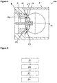
- Figure 3 shows a schematic sectional illustration of the valve 100 in the open position.
- Figure 4 shows a schematic sectional illustration of the valve 100 in the closed position.
- valve bodies 13 and 14 are in sealing contact with one valve seat 9. In other words, the two valve bodies 13 and 14 jointly close the valve opening 12.
- the first valve body 13 has a first contact area 18 which, in the closed position, is in contact with a corresponding first mating contact area 19 of the valve seat 9.
- a first seal 20 (valve seal) is formed.
- the second valve body 14 has a second contact area 21 which, in the closed position, is in contact with a corresponding first mating contact area 22 of the valve seat 9.
- a second seal 23 (valve seal) is formed.
- the first valve body 13 In the closed position, the first valve body 13 is pretensioned against the valve seat 9, for example by means of a spring (not shown) which acts on the plunger and is mounted on the housing 1, so that at least the leg 16 of the first valve body 13 is slightly elastically bent out of its relaxed position is.
- a spring not shown
- the valve 100 enables the advantages and functions mentioned at the outset.
- valve 100 according to Figures 2 to 4 can have a further valve seat, which can be sealed by means of two valve bodies in the same way as above.
- a combination is also conceivable in which one valve seat with two valve bodies and one with one valve body can be sealed.
- the first valve body 13 is fixed on the tappet 4, in particular welded.
- the tappet 4 is inserted into the housing 1 of the valve 100 and at least partially supported.
- a force is applied to the plunger 4, for example the spring force of a spring (not shown) (see description above).
- the plunger 4 is moved linearly along the longitudinal axis 11 into the closed position, the leg 16 sealingly abutting the valve seat 9 due to the force acting and at the same time being slightly elastically bent.
- step S4 after the tappet 4 has been inserted into the housing 1, the second valve body 14 is fixed on the tappet 4, in particular welded.
- the second valve body 14 is arranged in such a way that it also rests against the valve seat 9 in a sealing manner in the prevailing closed position.
Landscapes
- Engineering & Computer Science (AREA)
- General Engineering & Computer Science (AREA)
- Mechanical Engineering (AREA)
- Chemical & Material Sciences (AREA)
- Combustion & Propulsion (AREA)
- Lift Valve (AREA)
Description
- Die Erfindung betrifft ein Ventil zum Öffnen und Schließen von Abgasleitungen. Ein solches Ventil weist ein Gehäuse und einen darin angeordneten Stößel auf, der mit einem Antrieb koppelbar ist und ausgebildet ist mittels des Antriebs entlang einer Längsachse des Stößels bewegt zu werden. Im Gehäuse ist ein Ventilsitz angeordnet, der eine Ventilöffnung begrenzt und die mittels einer am Stößel angeordneten Ventilkörpervorrichtung abdichtend geschlossen bzw. freigegeben werden kann.
- Solche Ventile werden zum Öffnen und Verschließen von Abgasleitungen in Kraftfahrzeugen eingesetzt und sind aus dem Stand der Technik bekannt. Wichtig für die Funktion solcher Ventile ist die Dichtheit, mit der das Ventil die Leitung verschließt. Gerade bei Gasen ist das Erreichen einer geringen Leckrate mit hohem Aufwand verbunden. Beispielsweise ist entscheidend, die Position der Ventilkörpervorrichtung zu bestimmen, um so das Öffnen und Schließen des Ventils regeln zu können. Der Antrieb des Stößels wird typischerweise von einem Elektromotor und einem Getriebe gebildet. Das Getriebe dient dazu, die Drehbewegung des Elektromotors in eine translatorische Bewegung umzuwandeln, damit der mit dem Getriebe verbundene Stößel die Ventilkörpervorrichtung linear bewegen kann.
- Die
DE 10 2015 122379 A1 betrifft eine Ventilvorrichtung für eine Verbrennungskraftmaschine. DieUS 4 254 792 A bezieht sich auf ein Doppelsitzventil mit zwei Ventilscheiben, die sich unabhängig voneinander und relativ zueinander bewegen. DieUS 2005/279956 A1 betrifft ein Ventil, das insbesondere für gasförmige, flüssige Medien vorgesehen ist. DieWO 2018/140998 A1 betrifft eine Ventilanordnung für ein Saugmittel und eine Geruchsabsaugvorrichtung für eine Toilette. DieWO 2017/137961 A1 betrifft eine elektrische Ventilvorrichtung, die insbesondere in Haushaltsgeräten wie Waschmaschinen oder Geschirrspülern verwendet wird. DieEP 1 798 456 A1 bezieht sich auf ein Absperrventil, das für den Einsatz in einem gasbefeuerten Kessel, einer Gasverbrennungsvorrichtung oder dergleichen geeignet ist. - Eine Aufgabe, die der Erfindung zugrunde liegt, ist es, ein Konzept für ein Ventil anzugeben, welches eine besonders hohe Dichtheit des Ventils im Betrieb ermöglicht.
- Die Aufgabe wird gelöst durch die Gegenstände der unabhängigen Ansprüche.
- Erfindungsgemäß bzw. gemäß einem ersten Aspekt wird ein gattungsgemäßes Ventil offenbart, welches als Ventilkörpervorrichtung einen ersten und einen zweiten Ventilkörper aufweist, die jeweils mit dem Stößel verbunden sind, so dass die beiden Ventilkörper durch eine Bewegung des Stößels zwischen einer Offenstellung, in der die Ventilöffnung freigegeben ist, und einer Schließstellung, in der die beiden Ventilkörper an dem Ventilsitz anliegen und jeweils die Ventilöffnung abdichtend verschließen, verstellbar sind. Die beiden Ventilkörper weisen jeweils einen zylindrischen Abschnitt auf, mittels welchem diese auf den Stößel aufgeschoben und/oder aufgepresst sind. Der erste Ventilkörper weist einen abstehenden Schenkel auf, der ringförmig um die Längsachse umläuft und der sich unter einem Winkel bezüglich der Längsachse weg von dem Ventilsitz erstreckt. Der zweite Ventilkörper weist einen abstehenden Schenkel auf, der ringförmig um die Längsachse umläuft und der sich unter einem Winkel bezüglich der Längsachse hin zu dem Ventilsitz erstreckt. Die beiden Ventilkörper sind benachbart zueinander angeordnet. Der erste Ventilkörper ist bezogen auf die Längsachse näher am Ventilsitz angeordnet als der zweite Ventilkörper. Der zweite Ventilkörper erstreckt sich zumindest teilweise über den ersten Ventilkörper mit dessen Schenkel hinweg. Beide Schenkel sind federnd ausgebildet. Der erste Ventilkörper weist einen ersten Kontaktbereich auf, der in der Schließstellung an dem Ventilsitz anliegt zur Ausbildung einer ersten Dichtung. Der erste Kontaktbereich ist an dem Schenkel des ersten Ventilkörpers ausgebildet. Der zweite Ventilkörper weist einen zweiten Kontaktbereich auf, der an dem Schenkel des zweiten Ventilkörpers ausgebildet ist und der in der Schließstellung an dem Ventilsitz anliegt zur Ausbildung einer zweiten Dichtung, so dass die Ventilöffnung in der Schließstellung sowohl durch den ersten Ventilkörper als auch durch zweiten Ventilkörper abdichtbar ist.
- Das beschriebene Ventil zeichnet sich dadurch aus, dass zwei Ventilkörper am Stößel angeordnet sind, die in Schließstellung ein und dieselbe Ventilöffnung abdichten. Hierzu sind die beiden Ventilkörper aufgrund ihrer festen Kopplung mit dem Stößel simultan mittels des Stößels bewegbar und so ausgebildet, dass diese in der Schließstellung jeweils separat an dem gemeinsamen Ventilsitz anliegen.
- Die beiden Ventilkörper sind beispielsweise unmittelbar benachbart am Stößel bezogen auf die Längsachse angeordnet. Dadurch sind an einem Ventilsitz zwei Ventildichtungen bzw. zwei Ventilfunktionen ermöglicht. Dies ermöglicht eine besonders effektive Dichtheit des Ventils, da durch die beiden Ventilkörper für eine Ventilöffnung eine Redundanz ermöglicht ist und im Falle einer Leckage bei einem Ventilkörper immer noch die Dichtheit des Ventils über den andern Ventilkörper erzielt werden kann. Des Weiteren kann beispielsweise auf einen zusätzlichen Ventilsitz verzichtet und damit Kosten eingespart werden. Es wird zudem zu einer kostengünstigen Herstellung eines solchen Ventils beigetragen.
- Das beschriebene Ventil eignet sich insbesondere für Linearventile, bei denen der Stößel entlang einer Richtung, insbesondere seiner Längsachse, linear bewegt wird. Weiterhin kann das Ventil auch einen weiteren Ventilsitz mit einer weiteren Ventilöffnung aufweisen (Doppellinearventil), die gleichzeitig zur ersten Ventilöffnung durch die Stößelbewegung mittels einer entsprechenden Ventilkörpervorrichtung verschlossen oder freigegeben werden kann. Diese Ventilkörpervorrichtung kann wiederum zwei Ventilkörper für den einen weiteren Ventilsitz aufweisen, es ist aber auch ein einzelner Ventilkörper unter Ausbildung einer Dichtung vorstellbar.
- Beispielsweise ist das Ventil in einem Abgasrückführsystem eines Kraftfahrzeugs einsetzbar, um die Abgasleitung des Kraftfahrzeugs zu öffnen und zu schließen. Beispielsweise weist ein Abgasrückführsystem eines Kraftfahrzeugs das Ventil auf.
- Als Ventilsitz wird bevorzugt ein einstückiges Bauteil verstanden, welches im Gehäuse angeordnet ist, etwa eingepresst, und den Dichtkontakt mit den Ventilkörpern herstellt. Es kann sich alternativ auch um einen Abschnitt des Gehäuses handeln, der die Ventilöffnung begrenzt.
- Gemäß einer Ausführungsform sind einer oder beide Ventilkörper tellerartig ausgebildet. Beispielsweise handelt es sich um einen inneren tellerartigen und einen äußeren tellerartigen Ventilkörper, wobei der äußere Ventilkörper den inneren in radialer Richtung bezogen auf die Längsachse des Stößels überragt. Dadurch können beide Ventilkörper die Ventilöffnung wirksam abdichten. Die tellerartige Ausgestaltung ermöglicht zudem eine einfache und kostengünstige Herstellung.
- Gemäß einer Ausführungsform sind der erste Ventilkörper und/oder der zweite Ventilkörper mit dem Stößel verschweißt. Dies ermöglicht eine sichere und langzeitstabile Verbindung. Zudem ist eine einfache und kostengünstige Herstellung ermöglicht.
- Gemäß einer Ausführungsform sind der erste Ventilkörper und/oder der zweite Ventilkörper als Halbzeug gestanzt und in ihre endgültige Form umgeformt. Das Umformen umfasst beispielsweise einen Biegeherstellungsprozess. Dies trägt zu einer besonders kostengünstigen Herstellung bei, die einen besonders geringen Stückpreis ermöglicht. Weiterhin ist ein derartiger Ventilköper aufgrund der Ausgestaltung als gestanztes und umgeformtes Teil mit einer vorbestimmten Grundelastizität ausgestattet, wodurch Toleranzen mithilfe von einer Vorspannung ausgeglichen werden können und eine besonders gute Dichtheit erzielbar ist. Die Ventilkörper sind beispielsweise aus Blech, etwa Federblech, hergestellt.
- Erfindungsgemäß weist der erste Ventilkörper einen ersten Kontaktbereich auf, der in der Schließstellung an dem Ventilsitz anliegt zur Ausbildung einer ersten Dichtung, und wobei der zweite Ventilkörper einen zweiten Kontaktbereich aufweist, der in der Schließstellung an dem Ventilsitz anliegt zur Ausbildung einer zweiten Dichtung, so dass die Ventilöffnung in der Schließstellung sowohl durch den ersten Ventilkörper als auch durch den zweiten Ventilkörper abdichtbar ist. Dies ermöglicht die oben genannten Vorteile und Funktionen. Insbesondere bildet jeder Ventilkörper in der Schließstellung einen eigenen Kontaktbereich aus, der jeweils mit einem entsprechenden Gegenkontaktbereich des Ventilsitzes in der Schließstellung in Kontakt tritt.
- Die Kontaktbereiche sind beispielsweise um die Längsachse des Stößels herum umlaufend ausgebildet. Beispielsweise sind die Kontaktbereich ringförmig oder zylinderförmig vollständig um die Längsachse umlaufend. Die beiden Ventilkörper sind beispielswiese rotationssymmetrisch ausgebildet. Die beiden Kontaktbereiche können auch als Dichtflächen oder Dichtbereiche bezeichnet werden. Die Kontaktbereiche sind beispielsweise tellerartig oder scheibenartig ausgebildet.
- Erfindungsgemäß ist der erste Kontaktbereich an einem Schenkel des ersten Ventilkörpers ausgebildet, wobei sich der Schenkel des ersten Ventilkörpers in einer Richtung weg von dem Ventilsitz erstreckt. Zusätzlich oder alternativ ist der zweite Kontaktbereich an einem Schenkel des zweiten Ventilkörpers ausgebildet, wobei sich der Schenkel des zweiten Ventilkörpers in einer Richtung hin zu dem Ventilsitz erstreckt. Dies ermöglicht die oben genannten Vorteile und Funktionen.
- Die Schenkel sind bevorzugt ringförmig um die Längsachse des Stößels umlaufend ausgebildet. Die Schenkel des ersten beziehungsweise zweiten Ventilkörpers erstrecken sich entsprechend unter einem vorbestimmten Winkel bezüglich der Längsachse des Stößels zum Ventilsitz hin oder von diesem weg. Ein Schenkel kann auch als freier Endabschnitt oder Kontaktabschnitt des jeweiligen Ventilkörpers gesehen werden.
- Erfindungsgemäß sind die Schenkel des ersten Ventilkörpers und die des zweiten Ventilkörpers federnd ausgebildet. Dadurch wird - wie bereits oben erwähnt - dazu beigetragen Toleranzen auszugleichen und eine besonders wirksame Dichtheit zu erzielen. Auch wird eine effektive Montage, wie später noch beschrieben wird, ermöglicht.
- Gemäß einer Ausführungsform ist der erste Ventilkörper bezogen auf den Stößel näher an dem Ventilsitz angeordnet als der zweite Ventilkörper, und zumindest der federnde Schenkel des ersten Ventilkörpers ist in der Schließstellung elastisch verformt. Mittels eines derartigen Schenkels wird eine besonders wirksame Abdichtung des Ventilsitzes ermöglicht, indem beispielsweise der Schenkel unter Vorspannung in der Schließstellung am Ventilsitz anliegt. Der Schenkel wird beispielsweise in einer Richtung weg von dem Ventilsitz elastisch gebogen. Dadurch wirkt eine Federkraft auf den Ventilsitz, wodurch - wie bereits oben erwähnt - Toleranzen ausgeglichen werden können.
- Erfindungsgemäß bzw. gemäß einem weiteren Aspekt wird ein Verfahren zum Herstellen eines Ventils nach einer der zuvor beschriebenen Ausführungsformen offenbart, welches die folgenden Schritte umfasst:
- Festlegen eines ersten Ventilkörpers an dem Stößel, wobei der erste Ventilkörper zum Schließen bzw. Freigeben einer Ventilöffnung des Ventils ausgebildet ist,
- Einsetzen des Stößels in einem Gehäuse des Ventils,
- Bewegen des Stößels entlang der Längsachse in die Schließstellung derart, dass der erste Ventilkörper an einem Ventilsitz zum Schließen der Ventilöffnung abdichtend anliegt, und
- Festlegen eines zweiten Ventilkörpers an dem Stößel nach dem Bewegen des Stößels in die Schließstellung, so dass der zweite Ventilkörper an dem Ventilsitz anliegt.
- Das beschriebene Verfahren ermöglicht die Herstellung eines Ventils mit den oben erwähnten Vorteilen und Funktionen. Bei dem Verfahren werden nicht beide Ventilkörper gleichzeitig am Stößel montiert, sondern der Stößel und der montierte erste Ventilkörper werden als Einheit in das Gehäuse eingesetzt, ehe anschließend der zweite Ventilkörper montiert wird.
- Soweit nicht anders angegeben gelten die obigen Ausführungen zu dem Ventil und Weiterbildungen dessen analog auch für das Verfahren.
- Gemäß einer Ausführungsform wird im Schritt des Bewegens eine Kraft auf den Stößel aufgebracht, die den ersten Ventilkörper gegen den Ventilsitz drückt. Somit wird der zweite Ventilkörper erst montiert, wenn der erste Ventilkörper in der Schließstellung sicher abdichtend am Ventilsitz anliegt. Dadurch ist ermöglicht, dass der zweite Ventilkörper so montiert wird, dass dieser in der Schließstellung ebenfalls sicher abdichtend am Ventilsitz anliegt. Dies stellt sicher, dass beide Dichtfunktionen in der Schließstellung wirksam sind. Die Kraft wird beispielsweise durch eine Feder aufgebracht, die im oder am Gehäuse gelagert ist, auf den Stößel wirkt und diesen in Richtung des Ventilsitzes zieht.
- Gemäß einer Ausführungsform liegt in der Schließstellung der erste Ventilkörper mit einem federnden Schenkel dichtend an dem Ventilsitz und eine Kraft ist derart auf den ersten Ventilkörper aufgebracht, dass der federnde Schenkel elastisch verformt ist. Dadurch werden die obigen Vorteile und Funktionen ermöglicht.
- Weitere Vorteile, Merkmale und Weiterbildungen ergeben sich aus der nachfolgenden, in Verbindung mit den Figuren erläuterten Beschreibung eines Ausführungsbeispiels. Gleiche, gleichartige oder gleichwirkende Elemente können in den Figuren mit den gleichen Bezugszeichen versehen sein.
- In den Figuren zeigen:
- Figur 1
- eine schematische Schnittansicht eines exemplarischen Ventils,
- Figur 2
- eine schematische, perspektivische Ansicht eines Ventils gemäß einem Ausführungsbeispiel der Erfindung,
- Figur 3
- eine schematische Schnittansicht des Ventils gemäß
Figur 2 in einer Offenstellung, - Figur 4
- eine schematische Schnittansicht des Ventils gemäß
Figur 2 in einer Schließstellung, und - Figur 5
- ein schematisches Ablaufdiagramm eines Verfahrens zum Herstellen eines Ventils gemäß
Figur 2 . - Das exemplarische Ventil 100 in
Figur 1 weist ein Gehäuse 1 auf, in dem ein Elektromotor 2 angeordnet ist. Mittels eines Getriebes 3 wird die Drehbewegung des Elektromotors 2 in eine lineare Bewegung eines Stößels 4 umgewandelt. Am Getriebe 3 ist ein Sensor 5 angeordnet, der mit einem am Stößel 4 befestigten Magneten zusammenwirkt. Der Stößel 4 erstreckt sich von der Getriebekammer 6 bis in eine Ventilkammer 7, wobei der Stößel 4 an zwei Stellen 8 gelagert ist. Die Ventilkammer 7 besteht aus drei hintereinander liegenden Teilkammern 7a, 7b, 7c, die jeweils durch einen Ventilsitz 9 voneinander getrennt sind. Zwei Ventilkörper 10 sind so auf dem Stößel 4 angeordnet, dass sie sich bei einer linearen Bewegung des Stößels 4 entlang einer Längsachse 11 des Stößels 4 an den jeweiligen Ventilsitz 9 anlegen und eine entsprechende Ventilöffnung 12 abdichten oder sich vom Ventilsitz 9 wegbewegen und die entsprechende Ventilöffnung 12 somit freigeben, so dass ein Gas von einer Ventilkammer 7 in die andere strömen kann. - Im Folgenden wird ein Ventil 100 gemäß einem Ausführungsbeispiel der Erfindung beschrieben, welches eine verbesserte Abdichtung einer Ventilöffnung 12 aufweist. Im Übrigen kann das Ventil 100 die Merkmale der anhand von
Figur 1 beschriebenen Ausgestaltung aufweisen. Es sei jedoch darauf hingewiesen, dass das inFigur 1 beschriebene Ventil 100 exemplarisch zu verstehen ist und alternativ auch anderweitige Ausgestaltungen haben kann. -
Figur 2 zeigt einen perspektivischen Ausschnitt des Ventils 100. Dargestellt ist ein Ventilsitz 9, der eine Ventilöffnung 12 begrenzt. Der Ventilsitz 9 ist beispielsweise fest in das Gehäuse 1 eingepresst. An dem Stößel 4 sind zwei tellerartige Ventilkörper 13 und 14 angeordnet. Die beiden Ventilkörper 13 und 14 sind in einem Stanz- und Umformprozess aus Blech, insbesondere Federblech, hergestellt. Die beiden Ventilkörper 13 und 14 sind ringförmig um die Längsachse 11 des Stößels 4 umlaufend ausgebildet und haben jeweils einen zylindrischen Abschnitt 15, mittels welchem diese auf den Stößel 4 aufgeschoben und/oder aufgepresst sind. Die beiden Ventilkörper 13 und 14 sind fest mit dem Stößel 4 verschweißt. InFigur 3 sind Verschweißungen 24 der beiden Ventilkörper 13, 14 mit dem Stößel 4 exemplarisch gekennzeichnet. - Der erste Ventilkörper 13 hat einen abstehenden Schenkel 16, der um die Längsachse 11 umläuft. Der Schenkel 16 erstreckt sich unter einem Winkel bezüglich der Längsachse 11 weg von dem Ventilsitz 9. Der zweite Ventilkörper 14 hat einen abstehenden Schenkel 17, der um die Längsachse 11 umläuft. Der Schenkel 17 erstreckt sich unter einem Winkel bezüglich der Längsachse 11 hin zu dem Ventilsitz 9. Die beiden Ventilkörper 13 und 14 sind benachbart zueinander angeordnet, wobei der zweite Ventilkörper 14 sich zumindest teilweise über den ersten Ventilkörper 13, insbesondere mit dessen Schenkel 17, hinweg erstreckt. Der erste Ventilkörper 13 ist bezogen auf die Längsachse 11 näher am Ventilsitz 9 angeordnet als der zweite Ventilkörper 14. Zumindest beide Schenkel 16 und 17 sind federnd ausgebildet.
- Wie bereits anhand von
Figur 1 beschrieben ist der Stößel 4 linear entlang der Längsachse 12 zwischen einer Schließstellung und einer Offenstellung bewegbar. Dabei werden die beiden Ventilkörper 13 und 14 simultan bewegt. Die beiden Ventilkörper 13 und 14 sind so angeordnet und ausgebildet, dass diese die Ventilöffnung 12 verschließen bzw. freigeben können. InFigur 2 ist die Offenstellung gezeigt, in welcher die Ventilöffnung 12 freigegeben, das heißt geöffnet, ist. - Die Funktionalität des Ventils 100 ist anhand der
Figuren 3 und4 genauer erläutert.Figur 3 zeigt eine schematische Schnittdarstellung des Ventils 100 in der Offenstellung.Figur 4 zeigt eine schematische Schnittdarstellung des Ventils 100 in der Schließstellung. - In der Schließstellung (
Figur 4 ) liegen beide Ventilkörper 13 und 14 abdichtend an dem einen Ventilsitz 9 an. Mit anderen Worten verschließen die beiden Ventilkörper 13 und 14 die Ventilöffnung 12 gemeinsam. Der erste Ventilkörper 13 hat einen ersten Kontaktbereich 18, der in der Schließstellung mit einem entsprechenden ersten Gegenkontaktbereich 19 des Ventilsitzes 9 in Kontakt ist. Dabei ist eine erste Dichtung 20 (Ventildichtung) ausgebildet. Der zweite Ventilkörper 14 hat einen zweiten Kontaktbereich 21, der in der Schließstellung mit einem entsprechenden ersten Gegenkontaktbereich 22 des Ventilsitzes 9 in Kontakt ist. Dabei ist eine zweite Dichtung 23 (Ventildichtung) ausgebildet. - In der Schließstellung ist der erste Ventilkörper 13 derart gegen den Ventilsitz 9 vorgespannt, etwa mittels einer nicht gezeigten Feder, die auf den Stößel wirkt und am Gehäuse 1 gelagert ist, dass zumindest der Schenkel 16 des ersten Ventilkörpers 13 leicht elastisch aus seiner entspannten Position verbogen ist.
- Das Ventil 100 ermöglicht die eingangs genannten Vorteile und Funktionen.
- Das Ventil 100 gemäß
Figuren 2 bis 4 kann einen weiteren Ventilsitz haben, der analog zu oben mittels zweier Ventilkörper abgedichtet werden kann. Es ist jedoch auch eine Kombination denkbar, bei welcher ein Ventilsitz mit zwei Ventilkörpern und einer mit einem Ventilkörper abdichtbar sind. - Anhand von
Figur 5 wird ein Herstellungsverfahren für das Ventil 100 beschrieben. - Gemäß einem Schritt S1 wird der erste Ventilkörper 13 an dem Stößel 4 festgelegt, insbesondere verschweißt.
- In einem nächsten Schritt S2 wird der Stößel 4 in das Gehäuse 1 des Ventils 100 eingesetzt und zumindest teilweise gelagert.
- Anschließend wird der Stößel 4 in einem weiteren Schritt S3 mit einer Kraft beaufschlagt, etwa der Federkraft einer nicht gezeigten Feder (siehe Beschreibung oben). Dabei wird Stößel 4 linear entlang der Längsachse 11 in die Schließstellung bewegt, wobei durch die wirkende Kraft der Schenkel 16 an dem Ventilsitz 9 dichtend anliegt und gleichzeitig leicht elastisch verbogen wird.
- In einem weiteren Schritt S4 wird - nach dem Einsetzen des Stößels 4 in das Gehäuse 1 - der zweite Ventilkörper 14 am Stößel 4 festgelegt, insbesondere verschweißt. Der zweite Ventilkörper 14 wird so angeordnet, dass dieser in der vorherrschenden Schließstellung ebenfalls dichtend an dem Ventilsitz 9 anliegt.
Claims (8)
- Ventil (100) zum Öffnen und Schließen von Abgasleitungen, aufweisend- ein Gehäuse (1),- einen im Gehäuse (1) angeordneten Stößel (4), der mit einem Antrieb (2) koppelbar ist und ausgebildet ist mittels des Antriebs (2) entlang einer Längsachse (11) des Stößels (4) bewegt zu werden,- einen im Gehäuse (1) angeordneten Ventilsitz (9), der eine Ventilöffnung (12) begrenzt, und- einen ersten Ventilkörper (13) und einen zweiten Ventilkörper (14), die jeweils mit dem Stößel (4) verbunden sind, so dass die beiden Ventilkörper (13, 14) durch eine Bewegung des Stößels (4) zwischen einer Offenstellung, in der die Ventilöffnung (12) freigegeben ist, und einer Schließstellung, in der die beiden Ventilkörper (13, 14) an dem Ventilsitz (9) anliegen und jeweils die Ventilöffnung (12) abdichtend verschließen, verstellbar sind, wobei die beiden Ventilkörper (13, 14) ringförmig um die Längsachse (11) des Stößels (4) umlaufend ausgebildet sind und jeweils einen zylindrischen Abschnitt (15) aufweisen, mittels welchem diese auf den Stößel (4) aufgeschoben und/oder aufgepresst sind, der zweite Ventilkörper (14) einen abstehenden Schenkel (17) aufweist, der ringförmig um die Längsachse (11) umläuft und der sich unter einem Winkel bezüglich der Längsachse (11) hin zu dem Ventilsitz (9) erstreckt,
die beiden Ventilkörper (13, 14) benachbart zueinander angeordnet sind,
der erste Ventilkörper (13) bezogen auf die Längsachse (11) näher am Ventilsitz (9) angeordnet ist als der zweite Ventilkörper (14),
der zweite Ventilkörper (14) einen zweiten Kontaktbereich (21) aufweist, der an dem Schenkel (17) des zweiten Ventilkörpers (14) ausgebildet ist und der in der Schließstellung an dem Ventilsitz (9) anliegt zur Ausbildung einer zweiten Dichtung (23), so dass die Ventilöffnung (12) in der Schließstellung sowohl durch den ersten Ventilkörper (13) als auch durch zweiten Ventilkörper (14) abdichtbar ist, dadurch gekennzeichnet,
dass der erste Ventilkörper (13) einen abstehenden Schenkel (16) aufweist, der ringförmig um die Längsachse (11) umläuft und der sich unter einem Winkel bezüglich der Längsachse (11) weg von dem Ventilsitz (9) erstreckt und der erste Ventilkörper (13) einen ersten Kontaktbereich (18) aufweist, der an dem Schenkel (16) des ersten Ventilkörpers (13) ausgebildet ist und der in der Schließstellung an dem Ventilsitz (9) anliegt zur Ausbildung einer ersten Dichtung (20),
dass der zweite Ventilkörper (14) sich zumindest teilweise über den ersten Ventilkörper (13) mit dessen Schenkel (17) hinweg erstreckt und,
dass beide Schenkel (16, 17) federnd ausgebildet sind. - Ventil (100) nach Anspruch 1, wobei einer oder beide Ventilkörper (13, 14) tellerartig ausgebildet sind.
- Ventil (100) nach Anspruch 1 oder 2, wobei der erste Ventilkörper (13) und/oder der zweite Ventilkörper (14) mit dem Stößel (4) verschweißt sind.
- Ventil (100) nach einem der vorhergehenden Ansprüche, wobei der erste Ventilkörper (13) und/oder der zweite Ventilkörper (14) als Halbzeug gestanzt und in ihre endgültige Form umgeformt sind.
- Ventil (100) nach einem der vorhergehenden Ansprüche, wobei der erste Ventilkörper (13) bezogen auf den Stößel (4) näher an dem Ventilsitz (9) angeordnet ist als der zweite Ventilkörper (14), und wobei zumindest der federnde Schenkel (16) des ersten Ventilkörpers (13) in der Schließstellung elastisch verformt ist.
- Verfahren zum Herstellen eines Ventils (100) nach einem der vorhergehenden Ansprüche, umfassend die Schritte:- Festlegen eines ersten Ventilkörpers (13) an dem Stößel (4), wobei der erste Ventilkörper (13) zum Schließen bzw. Freigeben einer Ventilöffnung (12) des Ventils (100) ausgebildet ist,- Einsetzen des Stößels (4) in einem Gehäuse (1) des Ventils,- Bewegen des Stößels (4) entlang der Längsachse (11) in die Schließstellung derart, dass der erste Ventilkörper (13) an einem Ventilsitz (9) zum Schließen der Ventilöffnung (12) anliegt, und- Festlegen eines zweiten Ventilkörpers (14) an dem Stößel (4) nach dem Bewegen des Stößels (4) in die Schließstellung, so dass der zweite Ventilkörper (14) an dem Ventilsitz (9) anliegt.
- Verfahren nach Anspruch 6, wobei im Schritt des Bewegens eine Kraft auf den Stößel (4) aufgebracht wird, die den ersten Ventilkörper (13) gegen den Ventilsitz (9) drückt.
- Verfahren nach Anspruch 7, wobei in der Schließstellung der erste Ventilkörper (13) mit einem federnden Schenkel (16) dichtend an dem Ventilsitz (9) anliegt und wobei eine Kraft derart auf den ersten Ventilkörper (13) aufgebracht ist, dass der federnde Schenkel (16) elastisch verformt ist.
Priority Applications (1)
| Application Number | Priority Date | Filing Date | Title |
|---|---|---|---|
| EP18465572.8A EP3626948B1 (de) | 2018-09-18 | 2018-09-18 | Ventil sowie verfahren zum herstellen eines ventils |
Applications Claiming Priority (1)
| Application Number | Priority Date | Filing Date | Title |
|---|---|---|---|
| EP18465572.8A EP3626948B1 (de) | 2018-09-18 | 2018-09-18 | Ventil sowie verfahren zum herstellen eines ventils |
Publications (2)
| Publication Number | Publication Date |
|---|---|
| EP3626948A1 EP3626948A1 (de) | 2020-03-25 |
| EP3626948B1 true EP3626948B1 (de) | 2021-06-16 |
Family
ID=63965585
Family Applications (1)
| Application Number | Title | Priority Date | Filing Date |
|---|---|---|---|
| EP18465572.8A Active EP3626948B1 (de) | 2018-09-18 | 2018-09-18 | Ventil sowie verfahren zum herstellen eines ventils |
Country Status (1)
| Country | Link |
|---|---|
| EP (1) | EP3626948B1 (de) |
Family Cites Families (10)
| Publication number | Priority date | Publication date | Assignee | Title |
|---|---|---|---|---|
| DE2837298C2 (de) * | 1978-08-26 | 1984-05-24 | Holstein Und Kappert Gmbh, 4600 Dortmund | Doppelsitz-Hubventil |
| DE19539921C1 (de) * | 1995-10-26 | 1997-02-27 | Ranco Inc | Ventil |
| JP3846287B2 (ja) * | 2001-11-27 | 2006-11-15 | 三浦工業株式会社 | バルブ |
| DE102004028968B4 (de) * | 2004-06-16 | 2006-04-27 | Karl Dungs Gmbh & Co. Kg | Ventil mit sicherer Öffnungsanzeige |
| CA2575524A1 (en) * | 2004-07-29 | 2006-02-02 | Miura Co., Ltd. | Shut-off valve |
| US10760568B2 (en) * | 2013-03-14 | 2020-09-01 | ValveWorks, LLC | Multi-part valve assembly |
| DE102015122379B4 (de) * | 2015-12-21 | 2018-10-11 | Pierburg Gmbh | Ventilvorrichtung für eine Verbrennungskraftmaschine |
| ITUB20160705A1 (it) * | 2016-02-12 | 2017-08-12 | Elbi Int Spa | Dispositivo elettrovalvolare, in particolare per apparecchi elettrodomestici. |
| AU2018216626A1 (en) * | 2017-02-01 | 2019-09-26 | Geoffrey Charles Quick | A valve arrangement and an odour extraction device |
| TWI635224B (zh) * | 2017-08-08 | 2018-09-11 | 達霆精密工業有限公司 | 扣接裝置 |
-
2018
- 2018-09-18 EP EP18465572.8A patent/EP3626948B1/de active Active
Also Published As
| Publication number | Publication date |
|---|---|
| EP3626948A1 (de) | 2020-03-25 |
Similar Documents
| Publication | Publication Date | Title |
|---|---|---|
| EP3114378B1 (de) | Dichtung | |
| DE102011107024B4 (de) | STEUEREINRICHTUNG und Verfahren zur Herstellung derselben | |
| DE102014110849A1 (de) | Klappeneinrichtung | |
| WO2000025080A1 (de) | Rohrverbindung zwischen einem sammler eines kraftfahrzeugwärmetauschers und einer äusseren rohrleitung | |
| EP2040339A1 (de) | Steckverbinder mit Lamellenkontakt für Glühkerze | |
| DE112011102182B4 (de) | Hydraulisches Element | |
| EP3114345B1 (de) | Schalldämpfer | |
| WO2014139497A1 (de) | Lagerung für eine welle, insbesondere bei einer ventileinheit, mit einer solchen lagerung ausgestattete ventileinheit und verfahren zur herstellung | |
| DE102015209823A1 (de) | Betätigungseinrichtung | |
| DE102016223444B3 (de) | Optimiertes Klappenventil für ein Abgasklappensystem sowie Herstellungsverfahren dafür | |
| EP1936151B1 (de) | Verfahren zum Herstellen einer Vorrichtung zur Steuerung des Durchflusses eines gasförmigen oder flüssigen Mediums | |
| DE102012111923A1 (de) | Verfahren zum Verschließen einer Öffnung in einem Körper, insbesondere in einem Türbetätiger | |
| EP3626948B1 (de) | Ventil sowie verfahren zum herstellen eines ventils | |
| DE102004039776A1 (de) | Schalldämpfer sowie zugehöriges Herstellungsverfahren | |
| EP3628853B1 (de) | Ventil | |
| DE102011102018A1 (de) | Klappeneinrichtung | |
| EP3626950B1 (de) | Ventil sowie verfahren zum herstellen eines ventils | |
| DE102009039911A1 (de) | Umströmungseinrichtung für eine Aufladevorrichtung | |
| WO2014139500A2 (de) | Ventileinheit, wie abgasklappeneinheit für kraftfahrzeuge | |
| WO2015058915A1 (de) | Aktor für ventile in verbrennungskraftmaschinen | |
| EP3111122B1 (de) | Anordnung zur befestigung eines regelventils an einem strömungskanalgehäuse eines verbrennungsmotors | |
| DE102008027242B4 (de) | Verfahren zum Montieren einer Klappe in einem Gehäuse | |
| EP3628852B1 (de) | Ventil und verfahren zum herstellen eines ventils | |
| EP3626949B1 (de) | Ventil | |
| DE102015001475A1 (de) | Schaltanordnung für ein Kraftfahrzeug-Schaltgetriebe |
Legal Events
| Date | Code | Title | Description |
|---|---|---|---|
| PUAI | Public reference made under article 153(3) epc to a published international application that has entered the european phase |
Free format text: ORIGINAL CODE: 0009012 |
|
| STAA | Information on the status of an ep patent application or granted ep patent |
Free format text: STATUS: THE APPLICATION HAS BEEN PUBLISHED |
|
| AK | Designated contracting states |
Kind code of ref document: A1 Designated state(s): AL AT BE BG CH CY CZ DE DK EE ES FI FR GB GR HR HU IE IS IT LI LT LU LV MC MK MT NL NO PL PT RO RS SE SI SK SM TR |
|
| AX | Request for extension of the european patent |
Extension state: BA ME |
|
| RAP1 | Party data changed (applicant data changed or rights of an application transferred) |
Owner name: VITESCO TECHNOLOGIES GMBH |
|
| STAA | Information on the status of an ep patent application or granted ep patent |
Free format text: STATUS: REQUEST FOR EXAMINATION WAS MADE |
|
| 17P | Request for examination filed |
Effective date: 20200925 |
|
| RBV | Designated contracting states (corrected) |
Designated state(s): AL AT BE BG CH CY CZ DE DK EE ES FI FR GB GR HR HU IE IS IT LI LT LU LV MC MK MT NL NO PL PT RO RS SE SI SK SM TR |
|
| GRAP | Despatch of communication of intention to grant a patent |
Free format text: ORIGINAL CODE: EPIDOSNIGR1 |
|
| STAA | Information on the status of an ep patent application or granted ep patent |
Free format text: STATUS: GRANT OF PATENT IS INTENDED |
|
| INTG | Intention to grant announced |
Effective date: 20210121 |
|
| GRAS | Grant fee paid |
Free format text: ORIGINAL CODE: EPIDOSNIGR3 |
|
| GRAA | (expected) grant |
Free format text: ORIGINAL CODE: 0009210 |
|
| STAA | Information on the status of an ep patent application or granted ep patent |
Free format text: STATUS: THE PATENT HAS BEEN GRANTED |
|
| AK | Designated contracting states |
Kind code of ref document: B1 Designated state(s): AL AT BE BG CH CY CZ DE DK EE ES FI FR GB GR HR HU IE IS IT LI LT LU LV MC MK MT NL NO PL PT RO RS SE SI SK SM TR |
|
| REG | Reference to a national code |
Ref country code: GB Ref legal event code: FG4D Free format text: NOT ENGLISH |
|
| REG | Reference to a national code |
Ref country code: CH Ref legal event code: EP |
|
| REG | Reference to a national code |
Ref country code: DE Ref legal event code: R096 Ref document number: 502018005730 Country of ref document: DE |
|
| REG | Reference to a national code |
Ref country code: AT Ref legal event code: REF Ref document number: 1402512 Country of ref document: AT Kind code of ref document: T Effective date: 20210715 |
|
| REG | Reference to a national code |
Ref country code: IE Ref legal event code: FG4D Free format text: LANGUAGE OF EP DOCUMENT: GERMAN |
|
| REG | Reference to a national code |
Ref country code: LT Ref legal event code: MG9D |
|
| PG25 | Lapsed in a contracting state [announced via postgrant information from national office to epo] |
Ref country code: LT Free format text: LAPSE BECAUSE OF FAILURE TO SUBMIT A TRANSLATION OF THE DESCRIPTION OR TO PAY THE FEE WITHIN THE PRESCRIBED TIME-LIMIT Effective date: 20210616 Ref country code: HR Free format text: LAPSE BECAUSE OF FAILURE TO SUBMIT A TRANSLATION OF THE DESCRIPTION OR TO PAY THE FEE WITHIN THE PRESCRIBED TIME-LIMIT Effective date: 20210616 Ref country code: FI Free format text: LAPSE BECAUSE OF FAILURE TO SUBMIT A TRANSLATION OF THE DESCRIPTION OR TO PAY THE FEE WITHIN THE PRESCRIBED TIME-LIMIT Effective date: 20210616 Ref country code: BG Free format text: LAPSE BECAUSE OF FAILURE TO SUBMIT A TRANSLATION OF THE DESCRIPTION OR TO PAY THE FEE WITHIN THE PRESCRIBED TIME-LIMIT Effective date: 20210916 |
|
| REG | Reference to a national code |
Ref country code: NL Ref legal event code: MP Effective date: 20210616 |
|
| PG25 | Lapsed in a contracting state [announced via postgrant information from national office to epo] |
Ref country code: NO Free format text: LAPSE BECAUSE OF FAILURE TO SUBMIT A TRANSLATION OF THE DESCRIPTION OR TO PAY THE FEE WITHIN THE PRESCRIBED TIME-LIMIT Effective date: 20210916 Ref country code: LV Free format text: LAPSE BECAUSE OF FAILURE TO SUBMIT A TRANSLATION OF THE DESCRIPTION OR TO PAY THE FEE WITHIN THE PRESCRIBED TIME-LIMIT Effective date: 20210616 Ref country code: RS Free format text: LAPSE BECAUSE OF FAILURE TO SUBMIT A TRANSLATION OF THE DESCRIPTION OR TO PAY THE FEE WITHIN THE PRESCRIBED TIME-LIMIT Effective date: 20210616 Ref country code: SE Free format text: LAPSE BECAUSE OF FAILURE TO SUBMIT A TRANSLATION OF THE DESCRIPTION OR TO PAY THE FEE WITHIN THE PRESCRIBED TIME-LIMIT Effective date: 20210616 Ref country code: GR Free format text: LAPSE BECAUSE OF FAILURE TO SUBMIT A TRANSLATION OF THE DESCRIPTION OR TO PAY THE FEE WITHIN THE PRESCRIBED TIME-LIMIT Effective date: 20210917 |
|
| RAP4 | Party data changed (patent owner data changed or rights of a patent transferred) |
Owner name: VITESCO TECHNOLOGIES GMBH |
|
| REG | Reference to a national code |
Ref country code: DE Ref legal event code: R081 Ref document number: 502018005730 Country of ref document: DE Owner name: SCHAEFFLER TECHNOLOGIES AG & CO. KG, DE Free format text: FORMER OWNER: VITESCO TECHNOLOGIES GMBH, 30165 HANNOVER, DE Ref country code: DE Ref legal event code: R081 Ref document number: 502018005730 Country of ref document: DE Owner name: VITESCO TECHNOLOGIES GMBH, DE Free format text: FORMER OWNER: VITESCO TECHNOLOGIES GMBH, 30165 HANNOVER, DE |
|
| PG25 | Lapsed in a contracting state [announced via postgrant information from national office to epo] |
Ref country code: EE Free format text: LAPSE BECAUSE OF FAILURE TO SUBMIT A TRANSLATION OF THE DESCRIPTION OR TO PAY THE FEE WITHIN THE PRESCRIBED TIME-LIMIT Effective date: 20210616 Ref country code: ES Free format text: LAPSE BECAUSE OF FAILURE TO SUBMIT A TRANSLATION OF THE DESCRIPTION OR TO PAY THE FEE WITHIN THE PRESCRIBED TIME-LIMIT Effective date: 20210616 Ref country code: SK Free format text: LAPSE BECAUSE OF FAILURE TO SUBMIT A TRANSLATION OF THE DESCRIPTION OR TO PAY THE FEE WITHIN THE PRESCRIBED TIME-LIMIT Effective date: 20210616 Ref country code: SM Free format text: LAPSE BECAUSE OF FAILURE TO SUBMIT A TRANSLATION OF THE DESCRIPTION OR TO PAY THE FEE WITHIN THE PRESCRIBED TIME-LIMIT Effective date: 20210616 Ref country code: CZ Free format text: LAPSE BECAUSE OF FAILURE TO SUBMIT A TRANSLATION OF THE DESCRIPTION OR TO PAY THE FEE WITHIN THE PRESCRIBED TIME-LIMIT Effective date: 20210616 Ref country code: NL Free format text: LAPSE BECAUSE OF FAILURE TO SUBMIT A TRANSLATION OF THE DESCRIPTION OR TO PAY THE FEE WITHIN THE PRESCRIBED TIME-LIMIT Effective date: 20210616 Ref country code: RO Free format text: LAPSE BECAUSE OF FAILURE TO SUBMIT A TRANSLATION OF THE DESCRIPTION OR TO PAY THE FEE WITHIN THE PRESCRIBED TIME-LIMIT Effective date: 20210616 Ref country code: PT Free format text: LAPSE BECAUSE OF FAILURE TO SUBMIT A TRANSLATION OF THE DESCRIPTION OR TO PAY THE FEE WITHIN THE PRESCRIBED TIME-LIMIT Effective date: 20211018 |
|
| PG25 | Lapsed in a contracting state [announced via postgrant information from national office to epo] |
Ref country code: PL Free format text: LAPSE BECAUSE OF FAILURE TO SUBMIT A TRANSLATION OF THE DESCRIPTION OR TO PAY THE FEE WITHIN THE PRESCRIBED TIME-LIMIT Effective date: 20210616 |
|
| REG | Reference to a national code |
Ref country code: DE Ref legal event code: R097 Ref document number: 502018005730 Country of ref document: DE |
|
| PLBE | No opposition filed within time limit |
Free format text: ORIGINAL CODE: 0009261 |
|
| STAA | Information on the status of an ep patent application or granted ep patent |
Free format text: STATUS: NO OPPOSITION FILED WITHIN TIME LIMIT |
|
| PG25 | Lapsed in a contracting state [announced via postgrant information from national office to epo] |
Ref country code: DK Free format text: LAPSE BECAUSE OF FAILURE TO SUBMIT A TRANSLATION OF THE DESCRIPTION OR TO PAY THE FEE WITHIN THE PRESCRIBED TIME-LIMIT Effective date: 20210616 |
|
| REG | Reference to a national code |
Ref country code: CH Ref legal event code: PL |
|
| REG | Reference to a national code |
Ref country code: BE Ref legal event code: MM Effective date: 20210930 |
|
| 26N | No opposition filed |
Effective date: 20220317 |
|
| PG25 | Lapsed in a contracting state [announced via postgrant information from national office to epo] |
Ref country code: MC Free format text: LAPSE BECAUSE OF FAILURE TO SUBMIT A TRANSLATION OF THE DESCRIPTION OR TO PAY THE FEE WITHIN THE PRESCRIBED TIME-LIMIT Effective date: 20210616 Ref country code: AL Free format text: LAPSE BECAUSE OF FAILURE TO SUBMIT A TRANSLATION OF THE DESCRIPTION OR TO PAY THE FEE WITHIN THE PRESCRIBED TIME-LIMIT Effective date: 20210616 |
|
| PG25 | Lapsed in a contracting state [announced via postgrant information from national office to epo] |
Ref country code: LU Free format text: LAPSE BECAUSE OF NON-PAYMENT OF DUE FEES Effective date: 20210918 Ref country code: IT Free format text: LAPSE BECAUSE OF FAILURE TO SUBMIT A TRANSLATION OF THE DESCRIPTION OR TO PAY THE FEE WITHIN THE PRESCRIBED TIME-LIMIT Effective date: 20210616 Ref country code: IE Free format text: LAPSE BECAUSE OF NON-PAYMENT OF DUE FEES Effective date: 20210918 Ref country code: BE Free format text: LAPSE BECAUSE OF NON-PAYMENT OF DUE FEES Effective date: 20210930 |
|
| PG25 | Lapsed in a contracting state [announced via postgrant information from national office to epo] |
Ref country code: LI Free format text: LAPSE BECAUSE OF NON-PAYMENT OF DUE FEES Effective date: 20210930 Ref country code: CH Free format text: LAPSE BECAUSE OF NON-PAYMENT OF DUE FEES Effective date: 20210930 |
|
| GBPC | Gb: european patent ceased through non-payment of renewal fee |
Effective date: 20220918 |
|
| PG25 | Lapsed in a contracting state [announced via postgrant information from national office to epo] |
Ref country code: CY Free format text: LAPSE BECAUSE OF FAILURE TO SUBMIT A TRANSLATION OF THE DESCRIPTION OR TO PAY THE FEE WITHIN THE PRESCRIBED TIME-LIMIT Effective date: 20210616 |
|
| P01 | Opt-out of the competence of the unified patent court (upc) registered |
Effective date: 20230530 |
|
| PG25 | Lapsed in a contracting state [announced via postgrant information from national office to epo] |
Ref country code: HU Free format text: LAPSE BECAUSE OF FAILURE TO SUBMIT A TRANSLATION OF THE DESCRIPTION OR TO PAY THE FEE WITHIN THE PRESCRIBED TIME-LIMIT; INVALID AB INITIO Effective date: 20180918 |
|
| PG25 | Lapsed in a contracting state [announced via postgrant information from national office to epo] |
Ref country code: GB Free format text: LAPSE BECAUSE OF NON-PAYMENT OF DUE FEES Effective date: 20220918 |
|
| PG25 | Lapsed in a contracting state [announced via postgrant information from national office to epo] |
Ref country code: MK Free format text: LAPSE BECAUSE OF FAILURE TO SUBMIT A TRANSLATION OF THE DESCRIPTION OR TO PAY THE FEE WITHIN THE PRESCRIBED TIME-LIMIT Effective date: 20210616 |
|
| PG25 | Lapsed in a contracting state [announced via postgrant information from national office to epo] |
Ref country code: MT Free format text: LAPSE BECAUSE OF FAILURE TO SUBMIT A TRANSLATION OF THE DESCRIPTION OR TO PAY THE FEE WITHIN THE PRESCRIBED TIME-LIMIT Effective date: 20210616 |
|
| REG | Reference to a national code |
Ref country code: AT Ref legal event code: MM01 Ref document number: 1402512 Country of ref document: AT Kind code of ref document: T Effective date: 20230918 |
|
| PG25 | Lapsed in a contracting state [announced via postgrant information from national office to epo] |
Ref country code: AT Free format text: LAPSE BECAUSE OF NON-PAYMENT OF DUE FEES Effective date: 20230918 |
|
| PG25 | Lapsed in a contracting state [announced via postgrant information from national office to epo] |
Ref country code: AT Free format text: LAPSE BECAUSE OF NON-PAYMENT OF DUE FEES Effective date: 20230918 |
|
| REG | Reference to a national code |
Ref country code: DE Ref legal event code: R081 Ref document number: 502018005730 Country of ref document: DE Owner name: SCHAEFFLER TECHNOLOGIES AG & CO. KG, DE Free format text: FORMER OWNER: VITESCO TECHNOLOGIES GMBH, 93055 REGENSBURG, DE |
|
| PGFP | Annual fee paid to national office [announced via postgrant information from national office to epo] |
Ref country code: DE Payment date: 20250930 Year of fee payment: 8 |
|
| PGFP | Annual fee paid to national office [announced via postgrant information from national office to epo] |
Ref country code: FR Payment date: 20250922 Year of fee payment: 8 |
|
| PG25 | Lapsed in a contracting state [announced via postgrant information from national office to epo] |
Ref country code: TR Free format text: LAPSE BECAUSE OF FAILURE TO SUBMIT A TRANSLATION OF THE DESCRIPTION OR TO PAY THE FEE WITHIN THE PRESCRIBED TIME-LIMIT Effective date: 20210616 |
|
| PGFP | Annual fee paid to national office [announced via postgrant information from national office to epo] |
Ref country code: AT Payment date: 20260410 Year of fee payment: 5 |