EP3626698B1 - Diffusionsplatte und reinigungsturm - Google Patents
Diffusionsplatte und reinigungsturm Download PDFInfo
- Publication number
- EP3626698B1 EP3626698B1 EP18827439.3A EP18827439A EP3626698B1 EP 3626698 B1 EP3626698 B1 EP 3626698B1 EP 18827439 A EP18827439 A EP 18827439A EP 3626698 B1 EP3626698 B1 EP 3626698B1
- Authority
- EP
- European Patent Office
- Prior art keywords
- tubes
- tube
- fluid
- dispersion plate
- length
- Prior art date
- Legal status (The legal status is an assumption and is not a legal conclusion. Google has not performed a legal analysis and makes no representation as to the accuracy of the status listed.)
- Active
Links
Images






Classifications
-
- C—CHEMISTRY; METALLURGY
- C07—ORGANIC CHEMISTRY
- C07C—ACYCLIC OR CARBOCYCLIC COMPOUNDS
- C07C7/00—Purification; Separation; Use of additives
- C07C7/20—Use of additives, e.g. for stabilisation
-
- B—PERFORMING OPERATIONS; TRANSPORTING
- B01—PHYSICAL OR CHEMICAL PROCESSES OR APPARATUS IN GENERAL
- B01D—SEPARATION
- B01D3/00—Distillation or related exchange processes in which liquids are contacted with gaseous media, e.g. stripping
- B01D3/008—Liquid distribution
-
- B—PERFORMING OPERATIONS; TRANSPORTING
- B01—PHYSICAL OR CHEMICAL PROCESSES OR APPARATUS IN GENERAL
- B01D—SEPARATION
- B01D3/00—Distillation or related exchange processes in which liquids are contacted with gaseous media, e.g. stripping
- B01D3/009—Distillation or related exchange processes in which liquids are contacted with gaseous media, e.g. stripping in combination with chemical reactions
-
- C—CHEMISTRY; METALLURGY
- C07—ORGANIC CHEMISTRY
- C07C—ACYCLIC OR CARBOCYCLIC COMPOUNDS
- C07C11/00—Aliphatic unsaturated hydrocarbons
- C07C11/12—Alkadienes
- C07C11/16—Alkadienes with four carbon atoms
-
- C—CHEMISTRY; METALLURGY
- C07—ORGANIC CHEMISTRY
- C07C—ACYCLIC OR CARBOCYCLIC COMPOUNDS
- C07C7/00—Purification; Separation; Use of additives
- C07C7/148—Purification; Separation; Use of additives by treatment giving rise to a chemical modification of at least one compound
-
- Y—GENERAL TAGGING OF NEW TECHNOLOGICAL DEVELOPMENTS; GENERAL TAGGING OF CROSS-SECTIONAL TECHNOLOGIES SPANNING OVER SEVERAL SECTIONS OF THE IPC; TECHNICAL SUBJECTS COVERED BY FORMER USPC CROSS-REFERENCE ART COLLECTIONS [XRACs] AND DIGESTS
- Y02—TECHNOLOGIES OR APPLICATIONS FOR MITIGATION OR ADAPTATION AGAINST CLIMATE CHANGE
- Y02P—CLIMATE CHANGE MITIGATION TECHNOLOGIES IN THE PRODUCTION OR PROCESSING OF GOODS
- Y02P20/00—Technologies relating to chemical industry
- Y02P20/10—Process efficiency
Definitions
- the present invention relates to a dispersion plate, and particularly, to a dispersion plate used in a butadiene purification column.
- Butadiene has been used as an intermediate of numerous petrochemicals such as synthetic rubber and electronic materials, which is one of the most important basic oils in a petrochemical market, and the demand and value thereof has been gradually increasing.
- Butadiene may be obtained by purifying butadiene in a C 4 mixture.
- a first extraction system, a second extraction system, and a purification system are included.
- a process of removing impurities is performed in order to increase the purity of butadiene, which is carried out in a purification column.
- the purification column includes a dispersion plate and a catalyst layer therein, wherein steam injected from a lower portion thereof moves to an upper portion thereof, butadiene injected from the upper portion thereof moves to the lower portion thereof, and in the catalyst layer, a reaction for removing impurities occurs.
- the dispersion plate separates the flow of steam and butadiene from each other, such that the purification is performed efficiently.
- the dispersion plate includes a plurality of tubes through which butadiene and steam flow, and some of the tubes through which butadiene flows may be clogged by a popcorn-type impurity (hereinafter, referred to as a popcorn polymer) produced during the process.
- a popcorn-type impurity hereinafter, referred to as a popcorn polymer
- US 5 942197 A describes a reactor comprising a continuous wall enclosing a first reaction zone, wherein the first reaction zone includes a catalyst for causing a desired reaction between the liquid and the treat gas; a liquid inlet above the first reaction zone for allowing a portion of the liquid to enter the reactor; a gas inlet below the first reaction zone for allowing a portion of the treat gas to enter the reactor; a liquid outlet below the first reaction zone for allowing a reacted portion of the liquid to exit the reactor; a gas outlet above the first reaction zone for allowing a portion of the treat gas to exit the reactor; and a gas bypass device in the first reaction zone for allowing a portion of the treat gas to bypass a portion of the first reaction zone, the gas bypass device including a gas bypass regulating device for regulating the amount of treat gas which bypasses the first reaction zone.
- US 8 205 863 B2 describes a distributor for a liquid in a gas-liquid contacting vessel.
- a first member forms a plurality of apertures permitting a liquid to pass there-through.
- a first compartment is coupled to the first member forming a barrier proximate to a perimeter of a first aperture of the plurality of apertures.
- a second compartment is coupled to the first member forming a barrier proximate to a perimeter of a second aperture of the plurality of apertures.
- the present invention has been made in an effort to provide a dispersion plate for butadiene purification column in which purification efficiency is not reduced even if some of the tubes through which butadiene is discharged are clogged to raise a liquid level, and a purification column including the same.
- the present invention provides a dispersion plate for a purification column including a support plate, at least one first fluid tube penetrating through the support plate, and a plurality of second fluid tubes arranged to be spaced apart from the first fluid tube and surround the first fluid tube, wherein a length of at least one of the second fluid tubes is longer than a length of another one of the second fluid tubes, and is shorter than or equal to a length of the first fluid tube.
- the second fluid tubes may be arranged at a predetermined interval along a circumference of the first fluid tube.
- the second fluid tubes may include a first tube having a first length and a second tube having a second length longer than the first length, wherein the first tube and the second tube are alternately arranged along the circumference of the first fluid tube.
- Each of the second fluid tubes has an elliptical inlet in which a first end point positioned to be spaced apart from one surface of the support plate by a first distance, and a second end point positioned to be spaced apart from the one surface of the support plate by a second distance longer than the first distance are connected to each other.
- the second end point of the first tube is positioned on the same line as the first end point of the second tube.
- Diameters of the first tube and the second tube may be the same.
- the second fluid tubes may include a plurality of first tubes surrounding the first fluid tube, arranged at a predetermined interval, and having the same length; and a plurality of second tubes each positioned between adjacent first tubes and having different lengths, wherein lengths of the second tubes are longer than lengths of the first tubes.
- the first tubes may be arranged at angles in which the first fluid tube having a circular cross-section is evenly divided.
- the second fluid tubes may include the same number of first tubes and second tubes.
- Another embodiment of the present invention provides a purification column including a purification chamber having a lower portion into which steam is injected and an upper portion into which butadiene is injected, at least one dispersion plate as described above installed across the inside of the purification chamber, and at least one catalyst layer configured to remove impurities of butadiene.
- the at least one catalyst layer is positioned so as to be spaced apart from the dispersion plate.
- the butadiene tubes may have various lengths, whereby deterioration in purification efficiency may be minimized even if the tube is clogged due to a popcorn polymer.
- FIG. 1 is a schematic configuration diagram showing a purification column according to an exemplary embodiment of the present invention.
- a purification column 1000 includes a purification chamber 100, a dispersion plate 200 installed across the purification chamber 100, inlets H1 and H2 and outlets H3 and H4 for injecting and discharging fluid into/from the purification chamber 100, and a catalyst layer 300 for removing impurities.
- the purification chamber 100 provides a space in which butadiene is purified by reacting with a catalyst and separated from an external environment.
- the first inlet H1 is positioned at an upper portion of the purification chamber
- the second outlet H4 is positioned at a lower portion of the purification chamber to allow butadiene supplied from the upper portion of the purification chamber to the lower portion thereof and then purified to be discharged through the second outlet H4 at the lower portion thereof.
- the second inlet H2 is positioned at the lower portion of the purification chamber, and the first outlet H3 is positioned at the upper portion of the purification chamber 100 to allow steam supplied to the lower portion of the purification chamber 100 and then moving to the upper portion of the purification chamber 100 to be discharged through the first outlet H3.
- the catalyst layer 300 may be selected depending on the impurities to be removed from butadiene supplied, and may be a catalyst containing a metal.
- the dispersion plate 200 which is to separate the catalyst layer 300, butadiene and steam from one another, is installed across the purification chamber 100.
- FIG. 2 is a schematic perspective diagram showing a dispersion plate according to an exemplary embodiment of the present invention.
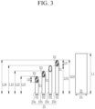
- FIG. 3 is a diagram for comparing and illustrating a length of a fluid tube included in FIG. 2 .
- FIG. 4 is a layout diagram showing a fluid tube included in one unit group included in FIG. 2 .
- the dispersion plate 200 includes a support plate 20, at least one first fluid tube 21 penetrating through the support plate 20, and a plurality of second fluid tubes 23 arranged to be spaced apart from the first fluid tube 21 and surround the first fluid tube 21.
- the second fluid tubes 23 may be arranged, at a predetermined interval, along the circumference of the first fluid tube 21.
- Vapor (steam) may flow through the first tube 21 and butadiene may flow through the second fluid tube 23.
- a diameter D1 of the first tube 21 may be larger than diameters D2 of the second fluid tubes 23.
- Lengths of the second fluid tubes 23 may be shorter than a length of the first fluid tube 21 and a length L1 of at least one of the second fluid tubes 23 is longer than a length L2 of another second fluid tube 23, but is not limited thereto, and three, four, or more second fluid tubes having different lengths may be formed.
- the second fluid tubes having four different lengths will be described as an example.
- the second fluid tube having the shortest length is referred to as a first tube 23a
- the second fluid tubes having different lengths, in the order of increasing lengths are each referred to as a second tube 23b, a third tube 23c and a fourth tube 23d.
- the second fluid tubes 23 are cut obliquely and inlets of the second fluid tubes 23 each have an elliptical inlet in which a first end point X1 positioned to be spaced apart from one surface of the support plate 20 by a first distance LD1, and a second end point X2 positioned to be spaced apart from the one surface of the support plate 20 by a second distance LD2 longer than the first distance LD1 are connected each other.
- the second end point is positioned relatively adjacent to the first fluid tube 21, and the first end point is positioned relatively far from the first fluid tube 21. Therefore, the elliptical inlets of the second fluid tubes 23 are arranged so as not to face the first fluid tube 21, thereby allowing butadiene to easily flow in.
- a difference between a length L21 of the first tube 23a and a length L22 of the second tube 23b, a difference between a length L22 of the second tube 23b and a length L23 of the third tube 23c, and a difference between a length L23 of the third tube 23c and a length L24 of the fourth tube 23d may be a difference LD (hereinafter, referred to as a height of the elliptical inlet) between the second distance LD2 and the first distance LD1, respectively.
- a difference LD hereinafter, referred to as a height of the elliptical inlet
- the second end point X2 of the first tube 23a is positioned on the same line as the first end point X1 of the second tube 23b
- the second end point X2 of the second tube 23b may be positioned on the same line as the first end point X1 of the third tube 23c
- the second end point X2 of the third tube 23c may be positioned on the same line as the first end point X1 of the fourth tube 23d.
- the one of the second fluid tubes having a longer length than another one of the second fluid tubes having a reference length when arranging one of the second fluid tubes having a longer length than another one of the second fluid tubes having a reference length, the one of the second fluid tubes having a longer length than the other one of the second fluid tubes having the reference length (or previously arranged) by a height LD of the elliptical inlet is arranged, and the second end point X2 of the other one of the second fluid tubes having the reference length and the first end point X1 of the one of the second fluid tubes arranged thereafter are arranged so as to be positioned on the same line.
- the dispersion plate 200 may include a plurality of unit groups G depending on a purification capacity of the purification column.
- the dispersion plate 200 may include seven unit groups G, and, the unit group G may be arranged at a predetermined interval in the support plate.
- one unit group G may include three first tubes 23a and three second tubes 23b, and the first tubes 23a and the second tubes 23b may be arranged alternately.
- one unit group G may include three first tubes 23a, one second tube 23b, one third tube 23c, and one fourth tube 23d, and the second tube 23b, the third tube 23c, and the fourth tube 23d may be arranged between adjacent first tubes 23a.
- the function of the dispersion plate may be extended although some of the second fluid tubes 23 are clogged due to popcorn polymer necessarily produced in addition to butadiene.
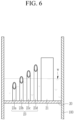
- FIG. 5 to FIG. 7 are schematic diagrams for explaining a fluid flow in the dispersion plate according to an exemplary embodiment of the present invention.
- the fluid tubes arranged in the order of their lengths are shown.
- butadiene is supplied from the upper portion of the purification column and stored on the support plate 20, and when the butadiene reaches a predetermined level or more, it is transferred to the catalyst layer at the lower portion of the purification column, through the second fluid tubes 23.
- Some of the plurality of second fluid tubes may be clogged by the popcorn polymer. Clogging due to the popcorn polymer results in a difference in flux of the supplied butadiene and the butadiene discharged through the second fluid tubes 23. Therefore, all of the supplied butadiene is not transferred to the catalyst layer but is stored, resulting in raising the height of the liquid level W of butadiene.
- butadiene may be discharged even while the liquid level rises and reaches the first fluid tube, thereby reducing the deterioration in purification efficiency.
- the second end point X2 of a second fluid tube which relatively first starts to discharge (for example, a first tube 23a which starts to discharge prior to the second tube 23b), and the first end point X1 of the second tube 23b starting the next discharge are positioned on the same line. Therefore, even if the liquid level rises, it is possible to perform a discharge immediately, thereby preventing the deterioration in the purification efficiency.
- the popcorn polymer together with butadiene may reach the catalyst layer through the first fluid tube, thereby reducing purification efficiency.
- the rise of the liquid level may delay as much as possible, thereby delaying the deterioration in purification efficiency due to the transfer of the popcorn polymer to the catalyst layer.
- FIG. 8 is a schematic layout diagram showing a dispersion plate according to another embodiment of the present invention.
- FIG. 9 is a diagram for comparing and illustrating the length of the fluid tubes included in FIG. 8 .
- the dispersion plate shown in FIG. 8 and FIG. 9 is mostly the same as that shown in FIG. 2 to FIG. 4 , and thus only different parts will be described in detail.
- one unit group is described as an example, and the dispersion plate may include such unit group in plural.
- a dispersion plate 202 may include the first fluid tube 21 and the second fluid tube 23, and the second fluid tubes 23 may include tubes 23a, 23b, 23c, 23d, and 23e having different lengths, and may be installed in multi-stages.
- the second fluid tubes 23 in FIG. 8 and FIG. 9 further include one more stage than the second fluid tubes in FIG. 2 to FIG. 4 .
- the reason may be that the distance from the first tube 23a to the first fluid tube 21 is longer than the distance from the first tube 23a to the first fluid tube 21 in FIG. 2 to FIG 4 , or the height LD of the inlet is short.
- the arrangement of the second fluid tubes in FIG. 2 to FIG. 4 and the second fluid tubes in FIG. 8 and FIG. 9 may be performed in the same manner.
- a reference tube is arranged at a predetermined interval along the circumference of the first fluid tube 21.
- the reference tube may be the first tubes 23a, and all of the first tubes 23a may have the same length and have the shortest length among the second fluid tubes.
- the second fluid tubes may be arranged radially from the center of the first fluid tube.
- the first tubes 23a since the number of the first tube 23a, which is the reference tube, is three, the first tubes 23a may be arranged at a position where the first fluid tube having a circular cross section is divided by 120 degrees.
- the first tubes 23a since the number of the first tube, which is the reference tube, is four, the first tubes 23a may be arranged at a position where the first fluid tube having a circular cross section is divided by 90 degrees.
- Intermediate tubes having longer lengths than the reference tube may be arranged between adjacent reference tubes, respectively.
- the intermediate tubes may be the second tube 23b, the third tube 23c, the fourth tube 23d, and the fifth tube 23e, all of these lengths may be different.
- the intermediate tubes having three different lengths may be arranged between adjacent reference tubes, respectively.
- the intermediate tubes having four different lengths may be arranged between adjacent reference tubes, respectively.
- the second fluid tubes having four stages in FIG. 4 and five stages in FIG. 8 are each escribed as an example, but is not limited thereto, and may include more or fewer number of stages.
- the reference tube may be arranged at an angle in which the first fluid tube having a circular cross-section is evenly divided, and the intermediate tubes may be arranged therebetween, the number of reference tubes and the number of intermediate tubes positioned between adjacent reference tubes may be the same.
- one intermediate tube is described except for the reference tube, but is not limited thereto, and depending on the flux of butadiene, there may be multiple intermediate tubes in each stage.
- the first fluid tube having a circular cross-section is described as an example, but is not limited thereto.
- the first fluid tube may have various cross-sections, such as a tetragon and pentagon.
- the second fluid tube may be arranged radially at a predetermined angle from the center of the first fluid tube, while surrounding the first fluid tube.
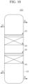
- the purification column having one dispersion plate is described, but is not limited thereto, and as shown in FIG. 10 , a plurality of dispersion plates may be installed, as necessary.
- FIG. 10 is a schematic configuration diagram showing a purification column according to another embodiment of the present invention.
- a purification column 1002 may include two dispersion plates 200 and may be installed in the order of the catalyst layer 300, the dispersion plate 200, the catalyst layer 300, and the dispersion plate 200 from the lower portion of the purification column.
Landscapes
- Chemical & Material Sciences (AREA)
- Organic Chemistry (AREA)
- Chemical Kinetics & Catalysis (AREA)
- Engineering & Computer Science (AREA)
- Analytical Chemistry (AREA)
- Oil, Petroleum & Natural Gas (AREA)
- Water Supply & Treatment (AREA)
- General Chemical & Material Sciences (AREA)
- Devices And Processes Conducted In The Presence Of Fluids And Solid Particles (AREA)
- Physical Or Chemical Processes And Apparatus (AREA)
- Organic Low-Molecular-Weight Compounds And Preparation Thereof (AREA)
Claims (8)
- Dispersionsplatte (200) aufweisend:eine Trägerplatte (20);mindestens ein erstes Fluidrohr (21), das durch die Trägerplatte (20) verläuft; undmehrere zweite Fluidrohre (23), die so angeordnet sind, dass sie von dem ersten Fluidrohr beabstandet sind und das erste Fluidrohr (21) umgeben,wobei eine Länge (L22-L24) mindestens eines der zweiten Fluidrohre (23) länger ist als eine Länge (L21-L23) eines anderen der zweiten Fluidrohre (23) und kürzer oder gleich einer Länge des ersten Fluidrohrs (21) ist,wobei jedes der zweiten Fluidrohre (23) einen elliptischen Einlass aufweist, der einen ersten Endpunkt (X1), der so positioniert ist, dass er von einer Oberfläche der Trägerplatte (20) um einen ersten Abstand (LD1) beabstandet ist, und einen zweiten Endpunkt (X2), der so positioniert ist, dass er von der einen Oberfläche der Trägerplatte (20) um einen zweiten Abstand (LD2) beabstandet ist, der länger ist als der erste Abstand (LD1), verbindet,wobei der zweite Endpunkt (X2) eines der zweiten Fluidrohre (23a-23c) auf derselben Linie positioniert ist wie der erste Endpunkt (X1) eines anderen der zweiten Fluidrohre (23b-23d),wobei der zweite Endpunkt (X2) relativ nahe an dem ersten Fluidrohr (21) positioniert ist und der erste Endpunkt (X1) relativ weit von dem ersten Fluidrohr (21) entfernt positioniert ist.
- Dispersionsplatte nach Anspruch 1, wobei:
die zweiten Fluidrohre (23) in regelmäßigen Abständen entlang eines Umfangs des ersten Fluidrohrs (21) angeordnet sind. - Dispersionsplatte nach Anspruch 2, wobei:
die zweiten Fluidrohre (23) Folgendes aufweisen:ein erstes Rohr (23a-23c) mit einer ersten Länge (L21-L23); undein zweites Rohr (23b-23d) mit einer zweiten Länge (L22-L24), die länger ist als die erste Länge (L21-L23),wobei das erste Rohr (23a-23c) und das zweite Rohr (23b-23d) abwechselnd entlang des Umfangs des ersten Fluidrohrs (23a-23c) angeordnet sind. - Dispersionsplatte nach Anspruch 3, wobei:
Durchmesser des ersten Rohrs (23a-23c) und des zweiten Rohrs (23b-23d) gleich sind. - Dispersionsplatte nach Anspruch 1, wobei:
die zweiten Fluidrohre Folgendes aufweisen:mehrere erste Rohre (23a-23c), die das erste Fluidrohr (21) umgeben, in einem vorgegebenen Abstand angeordnet sind und die gleiche Länge (L21-L23) aufweisen; undmehrere zweite Rohre (23b-23d), die jeweils zwischen benachbarten ersten Rohren (23a-23c) positioniert sind und unterschiedliche Längen (L22-L24) aufweisen,wobei Längen (L22-L24) der zweiten Rohre (23b-23d) länger sind als Längen (L21-L23) der ersten Rohre (23a-23c). - Dispersionsplatte nach Anspruch 5, wobei:
die ersten Rohre (23a-23c) unter Winkeln angeordnet sind, unter den das erste Fluidrohr (21), das einen kreisförmigen Querschnitt aufweist, gleichmäßig geteilt ist. - Dispersionsplatte nach Anspruch 6, wobei:
die zweiten Fluidrohre (23) die gleiche Anzahl von ersten Rohren (23a-23c) und zweiten Rohren (23b-23d) aufweisen. - Reinigungssäule (1000) aufweisend:eine Reinigungskammer (100) mit einem unteren Abschnitt (H2), in den Dampf eingespritzt wird, und einem oberen Abschnitt (H1), in den Butadien eingespritzt wird;mindestens eine Dispersionsplatte (200) nach einem der vorhergehenden Ansprüche, die über das Innere der Reinigungskammer (100) installiert ist; undmindestens eine Katalysatorschicht (300), die konfiguriert ist, um Verunreinigungen von Butadien zu entfernen, wobei die mindestens eine Katalysatorschicht (300) so positioniert ist, dass sie von der Dispersionsplatte (200) beabstandet ist.
Applications Claiming Priority (2)
| Application Number | Priority Date | Filing Date | Title |
|---|---|---|---|
| KR1020170086529A KR102086048B1 (ko) | 2017-07-07 | 2017-07-07 | 분산판 및 이를 포함하는 정제탑 |
| PCT/KR2018/007650 WO2019009647A1 (ko) | 2017-07-07 | 2018-07-05 | 분산판 및 이를 포함하는 정제탑 |
Publications (3)
| Publication Number | Publication Date |
|---|---|
| EP3626698A1 EP3626698A1 (de) | 2020-03-25 |
| EP3626698A4 EP3626698A4 (de) | 2020-06-03 |
| EP3626698B1 true EP3626698B1 (de) | 2025-02-26 |
Family
ID=64950180
Family Applications (1)
| Application Number | Title | Priority Date | Filing Date |
|---|---|---|---|
| EP18827439.3A Active EP3626698B1 (de) | 2017-07-07 | 2018-07-05 | Diffusionsplatte und reinigungsturm |
Country Status (6)
| Country | Link |
|---|---|
| US (1) | US11406911B2 (de) |
| EP (1) | EP3626698B1 (de) |
| JP (1) | JP7022156B2 (de) |
| KR (1) | KR102086048B1 (de) |
| CN (1) | CN110799479B (de) |
| WO (1) | WO2019009647A1 (de) |
Family Cites Families (27)
| Publication number | Priority date | Publication date | Assignee | Title |
|---|---|---|---|---|
| US3796657A (en) * | 1965-05-11 | 1974-03-12 | V Pretorius | Apparatus for distribution separation processes,their manufacture and use |
| US4526757A (en) * | 1982-11-01 | 1985-07-02 | Exxon Research And Engineering Co. | Pulsed flow vapor-liquid reactor |
| US5799877A (en) * | 1996-01-03 | 1998-09-01 | Exxon Research And Engineering Company | Fluid distribution across a particulate bed |
| FR2745202B1 (fr) | 1996-02-27 | 1998-04-30 | Inst Francais Du Petrole | Plateau pour distribuer un melange polyphasique a travers un lit catalytique |
| US5942197A (en) * | 1996-08-23 | 1999-08-24 | Exxon Research And Engineering Co | Countercurrent reactor |
| US6221117B1 (en) * | 1996-10-30 | 2001-04-24 | Idatech, Llc | Hydrogen producing fuel processing system |
| FR2807673B1 (fr) | 2000-04-17 | 2003-07-04 | Inst Francais Du Petrole | Dispositif de distribution d'un melange polyphasique sur un lit de solide granulaire comportant un element brise-jet poreux |
| DE10022465A1 (de) | 2000-05-09 | 2001-11-15 | Basf Ag | Verfahren und Vorrichtung zur Aufarbeitung eines C4-Schnitts aus der Fraktionierung von Erdöl |
| KR100741214B1 (ko) * | 2000-05-09 | 2007-07-19 | 바스프 악티엔게젤샤프트 | C4 분획을 처리하기 위한 방법 및 장치 |
| FR2832075B1 (fr) * | 2001-11-09 | 2005-02-04 | Inst Francais Du Petrole | Dispositif de distribution d'un melange polyphasique sur un lit de solide granulaire comportant un element brise jet poreux a rebords |
| CN2688707Y (zh) | 2004-01-19 | 2005-03-30 | 北京东方亚科力化工科技有限公司 | 丙烯酸异辛酯分离、精制、连续化生产装置 |
| US7506861B2 (en) | 2005-01-21 | 2009-03-24 | Morten Muller Ltd. Aps | Distribution device for two-phase concurrent downflow vessels |
| ITMI20050962A1 (it) | 2005-05-25 | 2006-11-26 | Lpe Spa | Dispositivo per introurre gas di reazione in una camera di reazione e reattore epitassiale che lo utilizza |
| PT2078552E (pt) * | 2008-01-09 | 2014-07-31 | Haldor Topsoe As | Dispositivo de distribuição líquido-vapor |
| US8205863B2 (en) * | 2008-06-03 | 2012-06-26 | Uop Llc | Distributor for a gas-liquid contacting vessel |
| FR2933877B1 (fr) | 2008-07-15 | 2011-04-15 | Inst Francais Du Petrole | Reacteur de traitement ou d'hydrotraitement avec un lit granulaire ainsi qu'une phase essentiellement liquide et une phase essentiellement gazeuse traversant le lit |
| US8372354B2 (en) | 2010-07-19 | 2013-02-12 | Chevron U.S.A. Inc. | Multiphase contact and distribution apparatus for hydroprocessing |
| KR101329029B1 (ko) | 2011-12-09 | 2013-11-13 | 주식회사 실리콘밸류 | 반응가스 공급노즐을 포함하는 유동층 반응기 |
| FR3006599B1 (fr) | 2013-06-10 | 2015-05-29 | IFP Energies Nouvelles | Plateau distributeur pour colonne de contact gaz/liquide avec systeme de distribution secondaire |
| WO2015076427A1 (ko) | 2013-11-19 | 2015-05-28 | 롯데케미칼 주식회사 | 올레핀 제조방법 |
| JP6759183B2 (ja) | 2014-07-08 | 2020-09-23 | ビーエーエスエフ ソシエタス・ヨーロピアBasf Se | 選択的溶媒を用いる抽出蒸留によって炭化水素及び/又は炭化水素誘導体の混合物を分離するための分離装置を有する塔 |
| FR3026019B1 (fr) * | 2014-09-24 | 2017-05-12 | Ifp Energies Now | Plateau distributeur compact pour les colonnes de contact gaz/liquide en mer |
| FR3030295B1 (fr) | 2014-12-17 | 2018-09-28 | IFP Energies Nouvelles | Plateau distributeur compact pour les colonnes de contact gaz/liquide en mer |
| KR102061238B1 (ko) | 2015-11-11 | 2019-12-31 | 주식회사 엘지화학 | 공액디엔 제조장치 및 제조방법 |
| CN206045985U (zh) | 2016-08-31 | 2017-03-29 | 中国石油化工股份有限公司 | 一种气液分配盘 |
| FR3067946A1 (fr) * | 2017-06-23 | 2018-12-28 | IFP Energies Nouvelles | Plateau distributeur pour colonne d'echange avec caisson pour la distribution du gaz |
| MX2020010733A (es) * | 2018-04-11 | 2020-12-09 | Lummus Technology Inc | Empaquetadura estructurada para destilación catalítica. |
-
2017
- 2017-07-07 KR KR1020170086529A patent/KR102086048B1/ko active Active
-
2018
- 2018-07-05 CN CN201880040729.8A patent/CN110799479B/zh active Active
- 2018-07-05 EP EP18827439.3A patent/EP3626698B1/de active Active
- 2018-07-05 US US16/625,565 patent/US11406911B2/en active Active
- 2018-07-05 JP JP2019569963A patent/JP7022156B2/ja active Active
- 2018-07-05 WO PCT/KR2018/007650 patent/WO2019009647A1/ko not_active Ceased
Also Published As
| Publication number | Publication date |
|---|---|
| JP7022156B2 (ja) | 2022-02-17 |
| KR20190005613A (ko) | 2019-01-16 |
| KR102086048B1 (ko) | 2020-03-06 |
| CN110799479A (zh) | 2020-02-14 |
| EP3626698A1 (de) | 2020-03-25 |
| US11406911B2 (en) | 2022-08-09 |
| US20210339162A1 (en) | 2021-11-04 |
| CN110799479B (zh) | 2022-04-19 |
| JP2020524596A (ja) | 2020-08-20 |
| WO2019009647A1 (ko) | 2019-01-10 |
| EP3626698A4 (de) | 2020-06-03 |
Similar Documents
| Publication | Publication Date | Title |
|---|---|---|
| US10576392B2 (en) | Distillation column and use thereof for cleaning isocyanates | |
| TWI322882B (en) | Annular distributor having guide vane to improve flow rate distribution, reactor/heat exchanger including the annular distributor and method of producing unsaturated aldehyde or unsaturated acid from olefin by catalytic gas phase oxidation in the reactor | |
| US10646795B2 (en) | Peripheral distribution or collection system for a simulated moving bed separation method using N columns in series | |
| KR20010006653A (ko) | 다운커머를 가지지 않는 천공 트레이, 다운커머를 가지지않는 천공트레이타워 및 증류방법 | |
| KR20150010664A (ko) | 증류 장치 | |
| US12030007B2 (en) | Apparatus for trapping reaction by-product created by etching process | |
| US6436245B1 (en) | Apparatus for the purification of organic compounds containing readily-blocking substances and process thereof | |
| EP3183045B1 (de) | Trennwandsäulen | |
| US11406911B2 (en) | Dispersion plate and purification column including the same | |
| US10137424B2 (en) | Distributor and down flow catalytic reactor comprising same | |
| AU2016221799B2 (en) | Shell and tube heat exchanger having sequentially arranged shell and tube components | |
| JPS5834162B2 (ja) | 蒸溜塔 | |
| CN104785072A (zh) | 具有液体分流器的用于气/液交换塔的分布器塔盘 | |
| CN108686590A (zh) | 使用串联的n个塔的模拟移动床分离方法的收集和分布通道的新颖构思 | |
| US10792635B2 (en) | Distributor and down flow catalytic reactor comprising same | |
| US20200108366A1 (en) | Apparatus for retaining solid material in a radial flow reactor and method of converting hydrocarbons | |
| US12017165B2 (en) | Distillation tray having through holes with different diameters | |
| EP3128165B1 (de) | Katalysatorkammer mit einem darin eingebetteten katalysatorbett für ein monopropellanten-triebwerk eines raketentriebwerks | |
| US20260084076A1 (en) | Reactive monomer separation device | |
| EP4691590A1 (de) | Vorrichtung zur trennung reaktiver monomere | |
| WO2015091442A1 (en) | Shell and tube heat exchanger with a shell having a polygonal section | |
| SU997705A1 (ru) | Массообменна тарелка | |
| WO2000010696A1 (en) | Tray contactor with same-direction liquid flow |
Legal Events
| Date | Code | Title | Description |
|---|---|---|---|
| STAA | Information on the status of an ep patent application or granted ep patent |
Free format text: STATUS: THE INTERNATIONAL PUBLICATION HAS BEEN MADE |
|
| PUAI | Public reference made under article 153(3) epc to a published international application that has entered the european phase |
Free format text: ORIGINAL CODE: 0009012 |
|
| STAA | Information on the status of an ep patent application or granted ep patent |
Free format text: STATUS: REQUEST FOR EXAMINATION WAS MADE |
|
| 17P | Request for examination filed |
Effective date: 20191217 |
|
| AK | Designated contracting states |
Kind code of ref document: A1 Designated state(s): AL AT BE BG CH CY CZ DE DK EE ES FI FR GB GR HR HU IE IS IT LI LT LU LV MC MK MT NL NO PL PT RO RS SE SI SK SM TR |
|
| AX | Request for extension of the european patent |
Extension state: BA ME |
|
| A4 | Supplementary search report drawn up and despatched |
Effective date: 20200504 |
|
| RIC1 | Information provided on ipc code assigned before grant |
Ipc: B01D 3/00 20060101ALI20200424BHEP Ipc: C07C 11/16 20060101ALI20200424BHEP Ipc: C07C 7/148 20060101ALI20200424BHEP Ipc: C07C 7/20 20060101AFI20200424BHEP Ipc: B01J 8/04 20060101ALI20200424BHEP Ipc: B01J 8/02 20060101ALI20200424BHEP |
|
| DAV | Request for validation of the european patent (deleted) | ||
| DAX | Request for extension of the european patent (deleted) | ||
| STAA | Information on the status of an ep patent application or granted ep patent |
Free format text: STATUS: EXAMINATION IS IN PROGRESS |
|
| 17Q | First examination report despatched |
Effective date: 20220411 |
|
| GRAP | Despatch of communication of intention to grant a patent |
Free format text: ORIGINAL CODE: EPIDOSNIGR1 |
|
| STAA | Information on the status of an ep patent application or granted ep patent |
Free format text: STATUS: GRANT OF PATENT IS INTENDED |
|
| INTG | Intention to grant announced |
Effective date: 20241106 |
|
| GRAS | Grant fee paid |
Free format text: ORIGINAL CODE: EPIDOSNIGR3 |
|
| GRAA | (expected) grant |
Free format text: ORIGINAL CODE: 0009210 |
|
| STAA | Information on the status of an ep patent application or granted ep patent |
Free format text: STATUS: THE PATENT HAS BEEN GRANTED |
|
| AK | Designated contracting states |
Kind code of ref document: B1 Designated state(s): AL AT BE BG CH CY CZ DE DK EE ES FI FR GB GR HR HU IE IS IT LI LT LU LV MC MK MT NL NO PL PT RO RS SE SI SK SM TR |
|
| REG | Reference to a national code |
Ref country code: GB Ref legal event code: FG4D |
|
| REG | Reference to a national code |
Ref country code: CH Ref legal event code: EP |
|
| REG | Reference to a national code |
Ref country code: DE Ref legal event code: R096 Ref document number: 602018079651 Country of ref document: DE |
|
| REG | Reference to a national code |
Ref country code: IE Ref legal event code: FG4D |
|
| REG | Reference to a national code |
Ref country code: NL Ref legal event code: MP Effective date: 20250226 |
|
| PG25 | Lapsed in a contracting state [announced via postgrant information from national office to epo] |
Ref country code: RS Free format text: LAPSE BECAUSE OF FAILURE TO SUBMIT A TRANSLATION OF THE DESCRIPTION OR TO PAY THE FEE WITHIN THE PRESCRIBED TIME-LIMIT Effective date: 20250526 |
|
| PG25 | Lapsed in a contracting state [announced via postgrant information from national office to epo] |
Ref country code: FI Free format text: LAPSE BECAUSE OF FAILURE TO SUBMIT A TRANSLATION OF THE DESCRIPTION OR TO PAY THE FEE WITHIN THE PRESCRIBED TIME-LIMIT Effective date: 20250226 |
|
| PG25 | Lapsed in a contracting state [announced via postgrant information from national office to epo] |
Ref country code: PL Free format text: LAPSE BECAUSE OF FAILURE TO SUBMIT A TRANSLATION OF THE DESCRIPTION OR TO PAY THE FEE WITHIN THE PRESCRIBED TIME-LIMIT Effective date: 20250226 |
|
| PG25 | Lapsed in a contracting state [announced via postgrant information from national office to epo] |
Ref country code: ES Free format text: LAPSE BECAUSE OF FAILURE TO SUBMIT A TRANSLATION OF THE DESCRIPTION OR TO PAY THE FEE WITHIN THE PRESCRIBED TIME-LIMIT Effective date: 20250226 |
|
| PGFP | Annual fee paid to national office [announced via postgrant information from national office to epo] |
Ref country code: GB Payment date: 20250624 Year of fee payment: 8 |
|
| REG | Reference to a national code |
Ref country code: LT Ref legal event code: MG9D |
|
| PG25 | Lapsed in a contracting state [announced via postgrant information from national office to epo] |
Ref country code: IS Free format text: LAPSE BECAUSE OF FAILURE TO SUBMIT A TRANSLATION OF THE DESCRIPTION OR TO PAY THE FEE WITHIN THE PRESCRIBED TIME-LIMIT Effective date: 20250626 Ref country code: NO Free format text: LAPSE BECAUSE OF FAILURE TO SUBMIT A TRANSLATION OF THE DESCRIPTION OR TO PAY THE FEE WITHIN THE PRESCRIBED TIME-LIMIT Effective date: 20250526 |
|
| PG25 | Lapsed in a contracting state [announced via postgrant information from national office to epo] |
Ref country code: NL Free format text: LAPSE BECAUSE OF FAILURE TO SUBMIT A TRANSLATION OF THE DESCRIPTION OR TO PAY THE FEE WITHIN THE PRESCRIBED TIME-LIMIT Effective date: 20250226 |
|
| PG25 | Lapsed in a contracting state [announced via postgrant information from national office to epo] |
Ref country code: HR Free format text: LAPSE BECAUSE OF FAILURE TO SUBMIT A TRANSLATION OF THE DESCRIPTION OR TO PAY THE FEE WITHIN THE PRESCRIBED TIME-LIMIT Effective date: 20250226 |
|
| PG25 | Lapsed in a contracting state [announced via postgrant information from national office to epo] |
Ref country code: LV Free format text: LAPSE BECAUSE OF FAILURE TO SUBMIT A TRANSLATION OF THE DESCRIPTION OR TO PAY THE FEE WITHIN THE PRESCRIBED TIME-LIMIT Effective date: 20250226 Ref country code: PT Free format text: LAPSE BECAUSE OF FAILURE TO SUBMIT A TRANSLATION OF THE DESCRIPTION OR TO PAY THE FEE WITHIN THE PRESCRIBED TIME-LIMIT Effective date: 20250626 |
|
| PGFP | Annual fee paid to national office [announced via postgrant information from national office to epo] |
Ref country code: FR Payment date: 20250624 Year of fee payment: 8 |
|
| PG25 | Lapsed in a contracting state [announced via postgrant information from national office to epo] |
Ref country code: GR Free format text: LAPSE BECAUSE OF FAILURE TO SUBMIT A TRANSLATION OF THE DESCRIPTION OR TO PAY THE FEE WITHIN THE PRESCRIBED TIME-LIMIT Effective date: 20250527 Ref country code: BG Free format text: LAPSE BECAUSE OF FAILURE TO SUBMIT A TRANSLATION OF THE DESCRIPTION OR TO PAY THE FEE WITHIN THE PRESCRIBED TIME-LIMIT Effective date: 20250226 |
|
| REG | Reference to a national code |
Ref country code: AT Ref legal event code: MK05 Ref document number: 1770530 Country of ref document: AT Kind code of ref document: T Effective date: 20250226 |
|
| PG25 | Lapsed in a contracting state [announced via postgrant information from national office to epo] |
Ref country code: SE Free format text: LAPSE BECAUSE OF FAILURE TO SUBMIT A TRANSLATION OF THE DESCRIPTION OR TO PAY THE FEE WITHIN THE PRESCRIBED TIME-LIMIT Effective date: 20250226 |
|
| PG25 | Lapsed in a contracting state [announced via postgrant information from national office to epo] |
Ref country code: SM Free format text: LAPSE BECAUSE OF FAILURE TO SUBMIT A TRANSLATION OF THE DESCRIPTION OR TO PAY THE FEE WITHIN THE PRESCRIBED TIME-LIMIT Effective date: 20250226 |
|
| PG25 | Lapsed in a contracting state [announced via postgrant information from national office to epo] |
Ref country code: DK Free format text: LAPSE BECAUSE OF FAILURE TO SUBMIT A TRANSLATION OF THE DESCRIPTION OR TO PAY THE FEE WITHIN THE PRESCRIBED TIME-LIMIT Effective date: 20250226 |
|
| PGFP | Annual fee paid to national office [announced via postgrant information from national office to epo] |
Ref country code: DE Payment date: 20250624 Year of fee payment: 8 |
|
| PG25 | Lapsed in a contracting state [announced via postgrant information from national office to epo] |
Ref country code: IT Free format text: LAPSE BECAUSE OF FAILURE TO SUBMIT A TRANSLATION OF THE DESCRIPTION OR TO PAY THE FEE WITHIN THE PRESCRIBED TIME-LIMIT Effective date: 20250226 |
|
| PG25 | Lapsed in a contracting state [announced via postgrant information from national office to epo] |
Ref country code: AT Free format text: LAPSE BECAUSE OF FAILURE TO SUBMIT A TRANSLATION OF THE DESCRIPTION OR TO PAY THE FEE WITHIN THE PRESCRIBED TIME-LIMIT Effective date: 20250226 |
|
| PG25 | Lapsed in a contracting state [announced via postgrant information from national office to epo] |
Ref country code: EE Free format text: LAPSE BECAUSE OF FAILURE TO SUBMIT A TRANSLATION OF THE DESCRIPTION OR TO PAY THE FEE WITHIN THE PRESCRIBED TIME-LIMIT Effective date: 20250226 Ref country code: CZ Free format text: LAPSE BECAUSE OF FAILURE TO SUBMIT A TRANSLATION OF THE DESCRIPTION OR TO PAY THE FEE WITHIN THE PRESCRIBED TIME-LIMIT Effective date: 20250226 |
|
| PG25 | Lapsed in a contracting state [announced via postgrant information from national office to epo] |
Ref country code: RO Free format text: LAPSE BECAUSE OF FAILURE TO SUBMIT A TRANSLATION OF THE DESCRIPTION OR TO PAY THE FEE WITHIN THE PRESCRIBED TIME-LIMIT Effective date: 20250226 |
|
| PG25 | Lapsed in a contracting state [announced via postgrant information from national office to epo] |
Ref country code: SK Free format text: LAPSE BECAUSE OF FAILURE TO SUBMIT A TRANSLATION OF THE DESCRIPTION OR TO PAY THE FEE WITHIN THE PRESCRIBED TIME-LIMIT Effective date: 20250226 |
|
| REG | Reference to a national code |
Ref country code: DE Ref legal event code: R097 Ref document number: 602018079651 Country of ref document: DE |
|
| PLBE | No opposition filed within time limit |
Free format text: ORIGINAL CODE: 0009261 |
|
| STAA | Information on the status of an ep patent application or granted ep patent |
Free format text: STATUS: NO OPPOSITION FILED WITHIN TIME LIMIT |
|
| REG | Reference to a national code |
Ref country code: CH Ref legal event code: L10 Free format text: ST27 STATUS EVENT CODE: U-0-0-L10-L00 (AS PROVIDED BY THE NATIONAL OFFICE) Effective date: 20260107 |
|
| 26N | No opposition filed |
Effective date: 20251127 |
|
| REG | Reference to a national code |
Ref country code: CH Ref legal event code: H13 Free format text: ST27 STATUS EVENT CODE: U-0-0-H10-H13 (AS PROVIDED BY THE NATIONAL OFFICE) Effective date: 20260224 |
|
| PG25 | Lapsed in a contracting state [announced via postgrant information from national office to epo] |
Ref country code: LU Free format text: LAPSE BECAUSE OF NON-PAYMENT OF DUE FEES Effective date: 20250705 |
|
| REG | Reference to a national code |
Ref country code: BE Ref legal event code: MM Effective date: 20250731 |
|
| PG25 | Lapsed in a contracting state [announced via postgrant information from national office to epo] |
Ref country code: BE Free format text: LAPSE BECAUSE OF NON-PAYMENT OF DUE FEES Effective date: 20250731 |
|
| PG25 | Lapsed in a contracting state [announced via postgrant information from national office to epo] |
Ref country code: CH Free format text: LAPSE BECAUSE OF NON-PAYMENT OF DUE FEES Effective date: 20250731 |