EP3626560B1 - Système de freinage pour véhicule et véhicule - Google Patents
Système de freinage pour véhicule et véhicule Download PDFInfo
- Publication number
- EP3626560B1 EP3626560B1 EP18195180.7A EP18195180A EP3626560B1 EP 3626560 B1 EP3626560 B1 EP 3626560B1 EP 18195180 A EP18195180 A EP 18195180A EP 3626560 B1 EP3626560 B1 EP 3626560B1
- Authority
- EP
- European Patent Office
- Prior art keywords
- brake
- control
- axle
- pneumatic
- pressure
- Prior art date
- Legal status (The legal status is an assumption and is not a legal conclusion. Google has not performed a legal analysis and makes no representation as to the accuracy of the status listed.)
- Active
Links
- 230000007257 malfunction Effects 0.000 claims description 20
- 230000003213 activating effect Effects 0.000 claims description 5
- 238000000034 method Methods 0.000 description 4
- 208000007150 epidermolysis bullosa simplex Diseases 0.000 description 3
- 238000012544 monitoring process Methods 0.000 description 3
- 230000003993 interaction Effects 0.000 description 1
- 230000001960 triggered effect Effects 0.000 description 1
Images

Classifications
-
- B—PERFORMING OPERATIONS; TRANSPORTING
- B60—VEHICLES IN GENERAL
- B60T—VEHICLE BRAKE CONTROL SYSTEMS OR PARTS THEREOF; BRAKE CONTROL SYSTEMS OR PARTS THEREOF, IN GENERAL; ARRANGEMENT OF BRAKING ELEMENTS ON VEHICLES IN GENERAL; PORTABLE DEVICES FOR PREVENTING UNWANTED MOVEMENT OF VEHICLES; VEHICLE MODIFICATIONS TO FACILITATE COOLING OF BRAKES
- B60T8/00—Arrangements for adjusting wheel-braking force to meet varying vehicular or ground-surface conditions, e.g. limiting or varying distribution of braking force
- B60T8/32—Arrangements for adjusting wheel-braking force to meet varying vehicular or ground-surface conditions, e.g. limiting or varying distribution of braking force responsive to a speed condition, e.g. acceleration or deceleration
- B60T8/88—Arrangements for adjusting wheel-braking force to meet varying vehicular or ground-surface conditions, e.g. limiting or varying distribution of braking force responsive to a speed condition, e.g. acceleration or deceleration with failure responsive means, i.e. means for detecting and indicating faulty operation of the speed responsive control means
- B60T8/92—Arrangements for adjusting wheel-braking force to meet varying vehicular or ground-surface conditions, e.g. limiting or varying distribution of braking force responsive to a speed condition, e.g. acceleration or deceleration with failure responsive means, i.e. means for detecting and indicating faulty operation of the speed responsive control means automatically taking corrective action
- B60T8/94—Arrangements for adjusting wheel-braking force to meet varying vehicular or ground-surface conditions, e.g. limiting or varying distribution of braking force responsive to a speed condition, e.g. acceleration or deceleration with failure responsive means, i.e. means for detecting and indicating faulty operation of the speed responsive control means automatically taking corrective action on a fluid pressure regulator
-
- B—PERFORMING OPERATIONS; TRANSPORTING
- B60—VEHICLES IN GENERAL
- B60T—VEHICLE BRAKE CONTROL SYSTEMS OR PARTS THEREOF; BRAKE CONTROL SYSTEMS OR PARTS THEREOF, IN GENERAL; ARRANGEMENT OF BRAKING ELEMENTS ON VEHICLES IN GENERAL; PORTABLE DEVICES FOR PREVENTING UNWANTED MOVEMENT OF VEHICLES; VEHICLE MODIFICATIONS TO FACILITATE COOLING OF BRAKES
- B60T13/00—Transmitting braking action from initiating means to ultimate brake actuator with power assistance or drive; Brake systems incorporating such transmitting means, e.g. air-pressure brake systems
- B60T13/10—Transmitting braking action from initiating means to ultimate brake actuator with power assistance or drive; Brake systems incorporating such transmitting means, e.g. air-pressure brake systems with fluid assistance, drive, or release
- B60T13/66—Electrical control in fluid-pressure brake systems
- B60T13/662—Electrical control in fluid-pressure brake systems characterised by specified functions of the control system components
-
- B—PERFORMING OPERATIONS; TRANSPORTING
- B60—VEHICLES IN GENERAL
- B60T—VEHICLE BRAKE CONTROL SYSTEMS OR PARTS THEREOF; BRAKE CONTROL SYSTEMS OR PARTS THEREOF, IN GENERAL; ARRANGEMENT OF BRAKING ELEMENTS ON VEHICLES IN GENERAL; PORTABLE DEVICES FOR PREVENTING UNWANTED MOVEMENT OF VEHICLES; VEHICLE MODIFICATIONS TO FACILITATE COOLING OF BRAKES
- B60T13/00—Transmitting braking action from initiating means to ultimate brake actuator with power assistance or drive; Brake systems incorporating such transmitting means, e.g. air-pressure brake systems
- B60T13/10—Transmitting braking action from initiating means to ultimate brake actuator with power assistance or drive; Brake systems incorporating such transmitting means, e.g. air-pressure brake systems with fluid assistance, drive, or release
- B60T13/24—Transmitting braking action from initiating means to ultimate brake actuator with power assistance or drive; Brake systems incorporating such transmitting means, e.g. air-pressure brake systems with fluid assistance, drive, or release the fluid being gaseous
- B60T13/26—Compressed-air systems
- B60T13/36—Compressed-air systems direct, i.e. brakes applied directly by compressed air
-
- B—PERFORMING OPERATIONS; TRANSPORTING
- B60—VEHICLES IN GENERAL
- B60T—VEHICLE BRAKE CONTROL SYSTEMS OR PARTS THEREOF; BRAKE CONTROL SYSTEMS OR PARTS THEREOF, IN GENERAL; ARRANGEMENT OF BRAKING ELEMENTS ON VEHICLES IN GENERAL; PORTABLE DEVICES FOR PREVENTING UNWANTED MOVEMENT OF VEHICLES; VEHICLE MODIFICATIONS TO FACILITATE COOLING OF BRAKES
- B60T13/00—Transmitting braking action from initiating means to ultimate brake actuator with power assistance or drive; Brake systems incorporating such transmitting means, e.g. air-pressure brake systems
- B60T13/10—Transmitting braking action from initiating means to ultimate brake actuator with power assistance or drive; Brake systems incorporating such transmitting means, e.g. air-pressure brake systems with fluid assistance, drive, or release
- B60T13/24—Transmitting braking action from initiating means to ultimate brake actuator with power assistance or drive; Brake systems incorporating such transmitting means, e.g. air-pressure brake systems with fluid assistance, drive, or release the fluid being gaseous
- B60T13/26—Compressed-air systems
- B60T13/38—Brakes applied by springs or weights and released by compressed air
- B60T13/385—Control arrangements therefor
-
- B—PERFORMING OPERATIONS; TRANSPORTING
- B60—VEHICLES IN GENERAL
- B60T—VEHICLE BRAKE CONTROL SYSTEMS OR PARTS THEREOF; BRAKE CONTROL SYSTEMS OR PARTS THEREOF, IN GENERAL; ARRANGEMENT OF BRAKING ELEMENTS ON VEHICLES IN GENERAL; PORTABLE DEVICES FOR PREVENTING UNWANTED MOVEMENT OF VEHICLES; VEHICLE MODIFICATIONS TO FACILITATE COOLING OF BRAKES
- B60T13/00—Transmitting braking action from initiating means to ultimate brake actuator with power assistance or drive; Brake systems incorporating such transmitting means, e.g. air-pressure brake systems
- B60T13/10—Transmitting braking action from initiating means to ultimate brake actuator with power assistance or drive; Brake systems incorporating such transmitting means, e.g. air-pressure brake systems with fluid assistance, drive, or release
- B60T13/66—Electrical control in fluid-pressure brake systems
- B60T13/68—Electrical control in fluid-pressure brake systems by electrically-controlled valves
- B60T13/683—Electrical control in fluid-pressure brake systems by electrically-controlled valves in pneumatic systems or parts thereof
-
- B—PERFORMING OPERATIONS; TRANSPORTING
- B60—VEHICLES IN GENERAL
- B60T—VEHICLE BRAKE CONTROL SYSTEMS OR PARTS THEREOF; BRAKE CONTROL SYSTEMS OR PARTS THEREOF, IN GENERAL; ARRANGEMENT OF BRAKING ELEMENTS ON VEHICLES IN GENERAL; PORTABLE DEVICES FOR PREVENTING UNWANTED MOVEMENT OF VEHICLES; VEHICLE MODIFICATIONS TO FACILITATE COOLING OF BRAKES
- B60T15/00—Construction arrangement, or operation of valves incorporated in power brake systems and not covered by groups B60T11/00 or B60T13/00
- B60T15/02—Application and release valves
- B60T15/025—Electrically controlled valves
- B60T15/027—Electrically controlled valves in pneumatic systems
-
- B—PERFORMING OPERATIONS; TRANSPORTING
- B60—VEHICLES IN GENERAL
- B60T—VEHICLE BRAKE CONTROL SYSTEMS OR PARTS THEREOF; BRAKE CONTROL SYSTEMS OR PARTS THEREOF, IN GENERAL; ARRANGEMENT OF BRAKING ELEMENTS ON VEHICLES IN GENERAL; PORTABLE DEVICES FOR PREVENTING UNWANTED MOVEMENT OF VEHICLES; VEHICLE MODIFICATIONS TO FACILITATE COOLING OF BRAKES
- B60T17/00—Component parts, details, or accessories of power brake systems not covered by groups B60T8/00, B60T13/00 or B60T15/00, or presenting other characteristic features
- B60T17/18—Safety devices; Monitoring
-
- B—PERFORMING OPERATIONS; TRANSPORTING
- B60—VEHICLES IN GENERAL
- B60T—VEHICLE BRAKE CONTROL SYSTEMS OR PARTS THEREOF; BRAKE CONTROL SYSTEMS OR PARTS THEREOF, IN GENERAL; ARRANGEMENT OF BRAKING ELEMENTS ON VEHICLES IN GENERAL; PORTABLE DEVICES FOR PREVENTING UNWANTED MOVEMENT OF VEHICLES; VEHICLE MODIFICATIONS TO FACILITATE COOLING OF BRAKES
- B60T8/00—Arrangements for adjusting wheel-braking force to meet varying vehicular or ground-surface conditions, e.g. limiting or varying distribution of braking force
- B60T8/17—Using electrical or electronic regulation means to control braking
- B60T8/1701—Braking or traction control means specially adapted for particular types of vehicles
-
- B—PERFORMING OPERATIONS; TRANSPORTING
- B60—VEHICLES IN GENERAL
- B60T—VEHICLE BRAKE CONTROL SYSTEMS OR PARTS THEREOF; BRAKE CONTROL SYSTEMS OR PARTS THEREOF, IN GENERAL; ARRANGEMENT OF BRAKING ELEMENTS ON VEHICLES IN GENERAL; PORTABLE DEVICES FOR PREVENTING UNWANTED MOVEMENT OF VEHICLES; VEHICLE MODIFICATIONS TO FACILITATE COOLING OF BRAKES
- B60T2270/00—Further aspects of brake control systems not otherwise provided for
- B60T2270/40—Failsafe aspects of brake control systems
- B60T2270/402—Back-up
-
- B—PERFORMING OPERATIONS; TRANSPORTING
- B60—VEHICLES IN GENERAL
- B60T—VEHICLE BRAKE CONTROL SYSTEMS OR PARTS THEREOF; BRAKE CONTROL SYSTEMS OR PARTS THEREOF, IN GENERAL; ARRANGEMENT OF BRAKING ELEMENTS ON VEHICLES IN GENERAL; PORTABLE DEVICES FOR PREVENTING UNWANTED MOVEMENT OF VEHICLES; VEHICLE MODIFICATIONS TO FACILITATE COOLING OF BRAKES
- B60T2270/00—Further aspects of brake control systems not otherwise provided for
- B60T2270/40—Failsafe aspects of brake control systems
- B60T2270/403—Brake circuit failure
-
- B—PERFORMING OPERATIONS; TRANSPORTING
- B60—VEHICLES IN GENERAL
- B60T—VEHICLE BRAKE CONTROL SYSTEMS OR PARTS THEREOF; BRAKE CONTROL SYSTEMS OR PARTS THEREOF, IN GENERAL; ARRANGEMENT OF BRAKING ELEMENTS ON VEHICLES IN GENERAL; PORTABLE DEVICES FOR PREVENTING UNWANTED MOVEMENT OF VEHICLES; VEHICLE MODIFICATIONS TO FACILITATE COOLING OF BRAKES
- B60T2270/00—Further aspects of brake control systems not otherwise provided for
- B60T2270/40—Failsafe aspects of brake control systems
- B60T2270/404—Brake-by-wire or X-by-wire failsafe
-
- B—PERFORMING OPERATIONS; TRANSPORTING
- B60—VEHICLES IN GENERAL
- B60T—VEHICLE BRAKE CONTROL SYSTEMS OR PARTS THEREOF; BRAKE CONTROL SYSTEMS OR PARTS THEREOF, IN GENERAL; ARRANGEMENT OF BRAKING ELEMENTS ON VEHICLES IN GENERAL; PORTABLE DEVICES FOR PREVENTING UNWANTED MOVEMENT OF VEHICLES; VEHICLE MODIFICATIONS TO FACILITATE COOLING OF BRAKES
- B60T2270/00—Further aspects of brake control systems not otherwise provided for
- B60T2270/40—Failsafe aspects of brake control systems
- B60T2270/414—Power supply failure
-
- B—PERFORMING OPERATIONS; TRANSPORTING
- B60—VEHICLES IN GENERAL
- B60T—VEHICLE BRAKE CONTROL SYSTEMS OR PARTS THEREOF; BRAKE CONTROL SYSTEMS OR PARTS THEREOF, IN GENERAL; ARRANGEMENT OF BRAKING ELEMENTS ON VEHICLES IN GENERAL; PORTABLE DEVICES FOR PREVENTING UNWANTED MOVEMENT OF VEHICLES; VEHICLE MODIFICATIONS TO FACILITATE COOLING OF BRAKES
- B60T2270/00—Further aspects of brake control systems not otherwise provided for
- B60T2270/82—Brake-by-Wire, EHB
-
- B—PERFORMING OPERATIONS; TRANSPORTING
- B62—LAND VEHICLES FOR TRAVELLING OTHERWISE THAN ON RAILS
- B62D—MOTOR VEHICLES; TRAILERS
- B62D5/00—Power-assisted or power-driven steering
Definitions
- the present invention relates to a brake system for a vehicle and to a vehicle with said brake system.
- DE 10 2008 009 043 B3 shows a redundant brake system for a commercial vehicle.
- the system utilizes a parking brake integrated into an air supply unit as a redundant brake actuator.
- a control output of a trailer control module is used as pneumatic control input of axle modulators.
- EP 2 794 368 B1 shows a redundant brake system for a commercial vehicle.
- the system utilizes the parking brake integrated into an air supply unit as a redundant brake actuator.
- the air supply unit includes an additional electro-pneumatic modulator to generate control pressure for the pneumatic control input of the axle modulators.
- a service brake demand signal is transmitted to an electronic parking brake controller responsive to an error signal representing a malfunction of a first control circuit comprising an electronic brake control.
- the system may comprise a brake system with three independent electric brake control circuits, which can be necessary for autonomous driving case, where the vehicle should be able to proceed its mission even in case of a single failure.
- There may be a switch between the redundant parts of the brake systems. According to an embodiment, such a switch may be automated. In case of any malfunction a secondary or a tertiary redundant brake system may be activated.
- a brake system for a vehicle comprises:
- the vehicle may be a utility vehicle or commercial vehicle, for example a truck, bus or the like.
- the first axle may be a front axle and the second axle a rear axle of the vehicle.
- the service brake chambers and the spring brake cylinders may represent brake actuators of the brake system or the vehicle.
- the pressure modulators, the electronic brake control unit, the intelligent foot brake module and the electronic parking brake controller may be common units as already used in vehicles.
- the electronic brake control unit, the intelligent foot brake module and the electronic parking brake controller may be redundantly used to activate the service brake chambers and the spring brake cylinders in case of a service brake demand.
- the service brake demand may be different to a park brake demand being used to activate the brakes while the vehicle is in or close to a parking position.
- the service brake demand may be triggered by a driver of the vehicle or by an electronic control unit for an automated driving mode. Due to the pressure control valve, the electronic parking brake controller may be used to activate the service brake chambers associated with the first axle additionally to the spring brake cylinders associated with the second axle in case of a service brake demand. Thus a redundant brake system can be realized.
- the electronic brake control unit may be part of a first control circuit, the intelligent foot brake module may be part of a second control circuit and the electronic parking brake controller may be part of a third control circuit.
- the first control circuit may be configured to provide a primary service brake functionality. If the brake system is intact, the electronic brake control may be used to activate the service brake chambers and the spring brake cylinders in case of a service brake demand. In the event of a malfunction of the first control circuit the second control circuit and/or the third control circuit are configured to provide redundant service brake functionalities. In the event of a malfunction of the first control circuit the intelligent foot brake module or the electronic parking brake controller may be used to activate the service brake chambers and the spring brake cylinders in case of a service brake demand. Thus, one of the second and third control circuits may be selected to replace the first control circuit in case of a malfunction of the first control circuit in order to execute a service brake demand.
- the brake system may comprise a first electric power supply unit, which may be connected to the electronic brake control unit.
- the first electric power supply may be configured to provide electric power necessary to run the electronic brake control unit.
- the brake system may comprise a second power supply unit, which may be connected to the intelligent foot brake module.
- the second electric power supply may be configured to provide electric power necessary to run the intelligent foot brake module.
- the brake system may comprise a third power supply unit, which may be connected to the electronic brake control unit.
- the third electric power supply may be configured to provide electric power necessary to run the electronic brake control unit. Thus there may be three independent electric power supplies.
- the brake system may comprise a first pneumatic selector valve being configured to select the first pneumatic control signal or the first pneumatic parking brake signal for controlling the first axle pressure modulator.
- the first pneumatic selector valve may provide a switching functionality for switching between the second control circuit and the third second control circuit with regard to the service brake chambers.
- the brake system may comprise a second pneumatic selector valve, being configured to connect the second pneumatic control signal to the second axle pressure modulator or to connect an exhaust port to the second axle pressure modulator.
- the first pneumatic selector valve may provide a switching functionality for switching between the second control circuit and the third second control circuit with regard to the spring brake cylinders.
- the pneumatic selector valves may have a default state. In the default state the pneumatic selector valves may be configured to select the first pneumatic control signal for controlling the first axle pressure modulator and configured to connect the second pneumatic control signal to the second axle pressure modulator to the second axle pressure modulator.
- the intelligent foot brake module can be used as a default replacement for the electronic brake control unit.
- the pneumatic selector valves may be configured to select the first pneumatic parking brake signal for controlling the first axle pressure modulator and configured to connect an exhaust port to the second axle pressure modulator.
- the electronic brake control unit can be used as a default replacement for the electronic brake control unit.
- the pressure control valve may be an inverting relay valve. Such a valve is costefficient and reliable.
- the brake system may comprise a trailer control module for controlling braking functions of a trailer of the vehicle.
- the electronic brake control unit may be configured to issue a third electric control signal for controlling the trailer control module.
- the intelligent foot brake module may be configured to issue the first pneumatic control signal further for controlling the trailer control module.
- the electronic parking brake controller may be configured to issue a third pneumatic parking brake signal for controlling the trailer control module.
- the trailer control module may be common unit as already used in vehicles. If the brake system is intact, the electronic brake control may be used to control the trailer control module. In the event of a malfunction of the first control circuit the intelligent foot brake module or the electronic parking brake controller may be used to control the trailer control module. Thus, one of the second and third control circuits may be selected to replace the first control circuit in case of a malfunction of the first control circuit with regard to activate the brakes of a trailer.
- the brake system may comprise a left pressure control valve and a right pressure control valve.
- the left pressure control valve may be configured to control a pressure of a left pneumatic pressure signal provided by the first axle pressure modulator for activating a left service brake chamber associated with a left wheel of the first axle of the vehicle.
- the right pressure control valve may be configured to control a pressure of a right pneumatic pressure signal provided by the first axle pressure modulator for activating a right service brake chamber associated with a right wheel of the first axle of the vehicle.
- the pressure provided to the left and the right service brake chambers may be adjusted individually.
- the electronic brake control unit may be configured to issue a left electric control signal for controlling the left pressure control valve and a right electric control signal for controlling the right pressure control valve.
- a redundant steering system can be realized.
- the autonomous driving has special demand against the steering system of an autonomous vehicle also.
- the intact steering system must be supplied with a redundant steering system, which requirement can be fulfilled by a special function of the brake system, namely the steer by braking.
- the brake system or the vehicle may comprise a steering gear unit.
- the steering gear unit and the electronic brake control unit may be connected to different electric power supply units.
- a vehicle comprises:
- the brake system may be used instead of a common brake system used for vehicles.
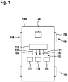
- Fig. 1 shows a schematic illustration of a vehicle 100 comprising a brake system 102 according to an embodiment of the present invention.
- the vehicle 100 is a utility vehicle or commercial vehicle, such as a truck.
- the vehicle 100 comprises a first axle 104, in particular a front axle, and at least one second axle 106, in particular a rear axle, according to this embodiment.
- the first axle 104 comprises a left wheel 108 and a right wheel 110.
- the brake system 102 comprises a first control circuit 112, a second control circuit 114 and a third control circuit 116.
- the first control circuit 112 is used to activate the brakes of the vehicle 100 in response to a service brake demand.
- the second control circuit 114 or the third control circuit 116 are used to activate the brakes of the vehicle in response to the service brake demand instead of the first control circuit 112.
- the third control circuit 116 is used to activate the brakes of the vehicle in response to the service brake demand.
- the vehicle 100 comprises an electronic control unit 118 (ECU) for controlling speed and optionally driving direction of the vehicle 100.
- the electronic control unit 118 may be connected to the control circuits 112, 114, 116 via a control unit interface, like a CAN-bus.
- the electronic control unit 118 is configured to provide a service brake demand signal 120.
- the electronic control unit 118 is configured to provide the service brake demand signal 120 to the first control circuit 112.
- the electronic control unit 118 is configured to provide the service brake demand signal 120 to the second control circuit 114 or the third control circuit 116, when an error signal 122 indicates a malfunction of the first control circuit 112.
- the electronic control unit 118 is configured to provide a switch signal 124, when the error signal 122 indicates a malfunction of the first control circuit 112, wherein the switch signal 124 is configured to switch from the first control circuit 112 to the second control circuit 114 or the third control circuit 116.
- the electronic control unit 118 may be part of the brake system 102.
- the control unit 118 is configured to provide the service brake demand while the vehicle is in a full or partial autonomous operation mode. In this case the control circuits 112, 114, 116 can be automatically operated without an interaction of a driver of the vehicle.
- the brake system 102 comprises a monitoring unit for monitoring a state of health of the brake system 102 and in particular of the first control circuit 112.
- the monitoring unit is configured to provide the error signal 122.
- the vehicle 100 comprises a steering gear unit 126 for steering the vehicle 100, for example by controlling a steering box assembly of the vehicle 100.
- the control unit 118 is configured to control the steering gear unit 126 in order to control the driving direction of the vehicle 100.
- the control unit 118 is configured to provide a steering demand, for example a steering signal 128.
- the steering signal 128 is used by one of the circuits 112, 114, 116 to control the driving direction by activating the brakes of the vehicle 100.
- Fig. 2 shows a schematic illustration of a brake system 102 according to an embodiment of the present invention.
- the brake system 102 corresponds or is similar to the brake system shown in Fig. 1 .
- the brake system 102 comprises a first electric power supply unit 201, a second electric power supply unit 202, and a third electric power supply unit 203.
- the brake system 102 further comprises an electronic brake control unit 220, an intelligent foot brake module 222 and an electronic parking brake controller 224, a first axle pressure modulator 228, a second axle pressure modulator 230, a left service brake chamber 232, a right service brake chamber 234, a left pressure control valve 236, a right pressure control valve 238 and two spring brake cylinders 240.
- the brake system 110 further comprises a first compressed air supply module 242, a second compressed air supply module 244 and a third compressed air supply module 246.
- the brake system 110 further comprises a pressure control valve 248, a first pneumatic selector valve 250 and a second pneumatic selector valve 252.
- the brake system 110 optionally comprises a trailer control module 254.
- the trailer control module 254 is configured to control braking functions of a trailer coupled to the vehicle.
- the trailer control module 254 is connected to the first compressed air supply module 242.
- the first electric power supply unit 201 and the electronic brake control unit 220 form part of the first control circuit
- the second electric power supply unit 202 and the intelligent foot brake module 222 form part of the second control circuit
- the third electric power supply unit 203 and the electronic parking brake controller 224 form part of the third control circuit described with reference to Fig. 1 .
- the first electric power supply unit 201 is electrically connected to the electronic brake control unit 220 via an analogous electric supply line.
- the second electric power supply unit 202 is electrically connected to the intelligent foot brake module 222 via a further analogous electric supply line.
- the third electric power supply unit 203 is electrically connected to the electronic parking brake controller 224 via a further analogous electric supply line.
- the electronic brake control unit 220 is electrically connected to the first axle pressure modulator 228 via an analogous electric signal or supply line and via a digital electric signal line. Furthermore, the electronic brake control unit 220 is electrically connected to the second axle pressure modulator 230 via an analogous electric signal or supply line and via a digital electric signal line. The electronic brake control unit 220 is configured to issue a first electric control signal for controlling the first axle pressure modulator 228 and a second electric control signal for controlling the second axle pressure modulator 230. Also, the electronic brake control unit 220 is electrically connected to the trailer control module 228 and to the intelligent foot brake module via analogous electric signal lines.
- the electronic brake control unit 220 is electrically connected to the left pressure control valve 236 and the right pressure control valve 238 via two separate analogous electric signal or supply lines.
- the electronic brake control unit 220 is configured to issue a left electric control signal for controlling the left pressure control valve 236 and a right electric control signal for controlling the right pressure control valve 238.
- the electronic brake control unit 220 can be used to control the driving direction of the vehicle additionally to or instead of a steering gear unit of the vehicle.
- the steering gear unit and the electronic brake control unit 220 are connected to different electric power supply units 201, 202, 203.
- the first axle pressure modulator 228, the service brake chambers 232, 234 and the pressure control valves 236, 238 are associated with a first axle of the vehicle.
- the first axle pressure modulator 228 is fluidically connected to the third compressed air supply module 246 via a pneumatic supply line
- the first axle pressure modulator 228 is fluidically connected to the left pressure control valve 236 via a pneumatic control line and to the right pressure control valve 238 via a further pneumatic control line.
- the left pressure control valve 236 is fluidically connected to the left service brake chamber 232 via a pneumatic control line and the right pressure control valve 238 is fluidically connected to the right service brake chamber 234 via a further pneumatic control line.
- first axle pressure modulator 228 is optionally electrically connected to a group of brake sensors for the first axle via analogous electric signal and supply lines.
- the second axle pressure modulator 230 and the spring brake cylinders 240 are associated with a second axle of the vehicle.
- the second axle pressure modulator 230 is fluidically connected to the second compressed air supply module 244 via a pneumatic supply line.
- the second axle pressure modulator 230 is fluidically connected to the spring brake cylinders 240 via pneumatic service brake control lines. Also, the second axle pressure modulator 230 is electrically connected to a group brake sensors for the second axle via analogous electric signal and supply lines.
- the electronic parking brake controller 224 is electrically connected to the pneumatic selector valves 250, 252 via an analogous electric signal line. Furthermore, the electronic parking brake controller 224 is electrically connected to the intelligent foot brake module 222 and optionally to a park brake lever sensor 256 via two separate analogous electric signal lines. The park brake lever sensor 256 can be operated by a driver of the vehicle in order to issue a park brake demand. Thus, the electronic parking brake controller 224 can be used to provide a park brake functionality and a service brake functionality.
- the electronic parking brake controller 224 is fluidically connected to the spring brake cylinders 240 and to the pressure control valve 248 via a pneumatic control line.
- the electronic parking brake controller 224 is configured to issue a second pneumatic parking brake signal for controlling the spring brake cylinders 240. Further, the electronic parking brake controller 224 is fluidically connected to the trailer control module 254 via a pneumatic brake control line.
- a first pressure control unit of the intelligent foot brake module 222 is fluidically connected to the third compressed air supply module 246 via a pneumatic supply line and to a second input of the first pneumatic selector valve 250 via a pneumatic control line.
- An output of the first pneumatic selector valve 250 is fluidically connected to the first axle pressure modulator 228 via a pneumatic control line.
- the intelligent foot brake module 222 is configured to issue a first pneumatic control signal for controlling the first axle pressure modulator 228 via the first pneumatic selector valve 250.
- a second pressure control unit of the intelligent foot brake module 222 is fluidically connected to the second compressed air supply module 244 via a pneumatic supply line and to a second input of the second pneumatic selector valve 252 via a pneumatic control line.
- An output of the second pneumatic selector valve 252 is fluidically connected to the second axle pressure modulator 228 via a pneumatic control line.
- a first input of the second pneumatic selector valve 252 is fluidically connected to an exhaust port via a pneumatic control line.
- the intelligent foot brake module 222 is configured to issue a second pneumatic control signal for controlling the second axle pressure modulator 230 via the second pneumatic selector valve 252.
- An input of the pressure control valve 248 is fluidically connected to the first compressed air supply module 242 via a pneumatic supply line.
- An output of the pressure control valve 248 is fluidically connected to a first input of the first pneumatic selector valve 250 via a pneumatic control line.
- the pressure control valve 248 is configured to convert the second pneumatic parking brake signal provided by the electronic parking brake controller 224 into a first pneumatic parking brake signal for controlling the first axle pressure modulator 228 via the first pneumatic selector valve 250.
- the electronic brake control unit 220 is configured to issue a third electric control signal for controlling the trailer control module 254
- the first pneumatic control signal provided by the intelligent foot brake module 222 is further used for controlling the trailer control module 25
- the electronic parking brake controller 224 is configured to issue a third pneumatic parking brake signal for controlling the trailer control module 254.
- Fig. 2 shows a schematic of a multiple redundant commercial vehicle electronic brake system 102 or electro-pneumatic brake system 102.
- the main components of the brake system 102 are described in the following.
- the first axle represents a front axle and the second axle represents a rear axle, thus “first” can be used as a synonym for "front” and “second” can be used as a synonym for "rear”.
- the brake system 102 is redundantly supplied by the power supply units 201, 202, 203 which are realized as separate batteries or power supplies.
- the primary EBS electronic brake control unit 220 is supplied from the first power supply unit 201.
- the electronic brake control unit 220 is electronically controlling the front axle pressure modulator 228, the pressure control valves 236, 238 on the front axle, the rear axle pressure modulator 230 and the trailer control module 254.
- the front axle wheel brakes are actuated by the service brake chambers 232, 234, while on the rear axle by spring brake cylinders 240 which are also known as spring brake combi cylinders.
- a first redundant pair, for example the second or secondary control circuit mentioned in Fig. 1 , of the brake system 102 is provided by the intelligent foot brake module 222 supplied by the second electric power supply unit 202.
- the intelligent foot brake module 222 is equipped with a pressure control unit, which can actuate the intelligent foot brake module 222 similar to a driver by his/her foot.
- the driven pressure by the pressure modulator unit of the intelligent foot brake module 222 is proportional to the pedal stroke.
- a second redundant pair, for example the third or tertiary control circuit mentioned in Fig. 1 , of the brake system 102 is provided by the electronic parking brake controller 224, also know as electronic parking brake (EPB) modulator, which is supplied by another battery, here the third electric power supply unit 203.
- the electronic parking brake controller 224 is actuating the spring brake cylinders 240 on the rear axle.
- the electronic parking brake controller 224 provides a pneumatic control signal to the trailer control module 254.
- the front axle or any other axles not equipped with spring brake cylinders 240 are controlled by the electronic parking brake controller 224 using a pressure control valve 248, for example an inverse relay or a proportional valve.
- the output of the pressure control valve 248 is commanding the pneumatic control pressure for the first axle pressure modulator 228.
- the service brake can be commanded by the driver by the redundant brake pedal sensor of the intelligent foot brake module 222, which provides separate demand signals for all the three control circuits.
- the parking brake can be commanded by the driver by the park brake lever sensor 256.
- the pressure control valve 248 can be a standalone unit or integrated into the electronic parking brake controller 224 or the first axle pressure modulator 228.
- the electronic parking brake controller 224 can be also a standalone unit or integrated into any other modules like a compressed air processing unit.
- pneumatic selector valves 250, 252 Switching between the secondary and tertiary redundant circuits is ensured by pneumatic selector valves 250, 252, for example by two 3/2 monostable solenoids.
- the default state can be any of the two but the example in Fig. 1 priories the secondary circuit.
- the pneumatic selector valves 250, 252 connects the output of the secondary control circuit, here the output of the intelligent foot brake module 222 to the backup port of the first axle pressure modulator 228 and the second axle pressure modulator 230. If the pneumatic selector valves 250, 252 are energized, then the output of the pressure control valve 248, for example the inverting relay valve, is connected to the backup port of first axle pressure modulator 228, and the backup port of the second axle pressure modulator 230 is exhausted to ambient.
- the service brake is controlled by the primary electronic brake control unit 220 as a master. It controls electronically its axle modules, here the first axle pressure modulator 228 and the second axle pressure modulator 230, and the trailer control module 254. So far it corresponds to the state of the art.
- the brake control is taken over by the secondary iFBM module, here the intelligent foot brake module 222.
- the driven pressure of the pressure modulator unit of the intelligent foot brake module 222 generates pedal stroke. Further operation of the intelligent foot brake module 222 is similar to a conventional foot brake module and generates control pressure for the axle modulators 228, 230.
- the pneumatic selector valves 250, 252 will be actuated and the brake control is taken over by the tertiary EPB module, here the electronic parking brake controller 224 and the axles equipped by spring brake chambers 240 are actuated by the parking brake control, while other axles without spring brake chamber 240 are controlled pneumatically through the pressure control valve 248, here the inverse valve, and through the first axle pressure modulator 228.
- the electronic parking brake controller 224 or its power supply here the third electric power supply unit 203 has any malfunction the primary EBS electronics, here the electronic brake control unit 220 is controlling the brake system 102 as in normal case and the parking brake function can be also simulated in the case by the service brake actuation.
- the brake system 102 further provides a redundant steering system.
- the primary EBS circuit comprising the electronic brake control unit 220, can generate different pressures on each side on the front axle with the help of the pressure control valves 236, 238 based on a steering demand as a redundancy for a steering gear.
- the steering gear may correspond to the steering gear unit as shown in Fig. 1 .
- the pressure difference between the left and the right side on the front axle causes a brake force difference sidewise, which causes a yaw-moment. Since the primary electronic brake control unit 220 is powered from the first electric power supply unit 201, therefore the steering gear should be supplied from the second electric power supply unit 202 and/or the third electric power supply unit 203.
- the brake system 102 of a commercial vehicle with an electro-pneumatic service brake system and an electro-pneumatic parking brake system, as shown in Fig. 2 comprises multiple redundancy, with control circuits more than two, in order that an automated vehicle can proceed its mission even in case of any single failure.
- the control circuits used for redundancy may be the second control circuit comprising the intelligent foot brake module and the third control circuit comprising the electronic parking brake controller 224.
- the brake control pressure of the second or the third brake circuits is selected by pneumatic selector valves 250, 252.
- the selector valves 250, 252 are connected in a way, that the backup control ports of the first axle pressure modulator 228 can be connected to the output of the foot brake module, for example the intelligent foot brake module 222, or to the pressure control valve 248 of the EPB system comprising the electronic parking brake controller 224.
- the backup port of the second axle pressure modulator 230 is exhausted to the ambient.
- the control valve 248 may be realized as an inverting relay valve.
- the default state of the pneumatic selector valves 250, 252 ensures the outputs of the intelligent foot brake module 222.
- the default state of the selector valves 250, 252 ensures the outputs of the electronic parking brake controller and the pressure control valve 248.
- the brake system 102 is driven to generate different brake pressure level via pressure control valves 236, 238 to the left and right brake chambers 232, 234 on the front axle based on the steering demand, which generates yaw-moment.
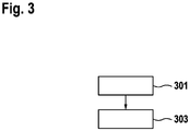
- Fig. 3 shows a flowchart of a method of controlling a brake system according to an embodiment of the present invention. The method is executable in connection with a brake system as described with reference to one of the preceding figures or a similar brake system.
- the method comprises a step 301 of receiving an error signal representing a malfunction of a first control circuit comprising the electronic brake control of the brake system and a step 303 of transmitting a service brake demand signal to the intelligent foot brake module or the electronic parking brake controller of the brake system responsive to the error signal.
Claims (11)
- Système de frein (102) pour un véhicule (100), dans lequel le système de frein (102) comprend :un premier modulateur de pression d'essieu (228) pour des vases à diaphragme (232, 234) associés à un premier essieu (104) du véhicule (100) ;un second modulateur de pression d'essieu (230) pour des cylindres de frein à ressort (240) associés à un second essieu (106) du véhicule (100) ;une unité de commande de frein électronique (220), dans lequel l'unité de commande de frein électronique (220) est configurée pour délivrer un premier signal de commande électrique pour commander le premier modulateur de pression d'essieu (228) et un deuxième signal de commande électrique pour commander le second modulateur de pression d'essieu (230) ;un dispositif de commande de frein de stationnement électronique (224), dans lequel le dispositif de commande de frein de stationnement électronique (224) est configuré pour délivrer un deuxième signal de frein de stationnement pneumatique pour commander les cylindres de frein à ressort (240) ;caractérisé parun module de frein au pied intelligent (222), dans lequel le module de frein au pied intelligent (222) est configuré pour délivrer un premier signal de commande pneumatique pour commander le premier modulateur de pression d'essieu (228) et un second signal de commande pneumatique pour commander le second modulateur de pression d'essieu (230) ; etune soupape de régulation de pression (248), dans lequel la soupape de régulation de pression (248) est configurée pour convertir le deuxième signal de frein de stationnement pneumatique en un premier signal de frein de stationnement pneumatique pour commander le premier modulateur de pression d'essieu (228).
- Système de frein (102) selon la revendication 1, dans lequel l'unité de commande de frein électronique (220) fait partie d'un premier circuit de commande (112), le module de frein au pied intelligent (222) fait partie d'un deuxième circuit de commande (114) et le dispositif de commande de frein de stationnement électronique (224) fait partie d'un troisième circuit de commande (116), dans lequel le premier circuit de commande (112) est configuré pour fournir une fonctionnalité de frein de service primaire et dans lequel en cas de dysfonctionnement du premier circuit de commande (112) le deuxième circuit de commande (114) et/ou le troisième circuit de commande (116) sont configurés pour fournir une fonctionnalité de frein de service redondante.
- Système de frein (102) selon l'une des revendications précédentes, comprenant une première unité d'alimentation en énergie électrique (201), dans lequel la première unité d'alimentation en énergie électrique (201) est connectée à l'unité de commande de frein électronique (220), une deuxième unité d'alimentation en énergie (202), dans lequel la deuxième unité d'alimentation en énergie électrique (202) est connectée au module de frein au pied intelligent (222), et une troisième unité d'alimentation en énergie (203), dans lequel la troisième unité d'alimentation en énergie électrique (203) est connectée à l'unité de commande de frein électronique (220).
- Système de frein (102) selon l'une des revendications précédentes, comprenant une première vanne de sélecteur pneumatique (250), dans lequel la première vanne de sélecteur pneumatique (250) est configurée pour sélectionner le premier signal de commande pneumatique ou le premier signal de frein de stationnement pneumatique pour commander le premier modulateur de pression d'essieu (228).
- Système de frein (102) selon l'une des revendications précédentes, comprenant une seconde vanne de sélecteur pneumatique (252), dans lequel la seconde vanne de sélecteur pneumatique (252) est configurée pour connecter le second signal de commande pneumatique au second modulateur de pression d'essieu (230) ou pour connecter un orifice d'échappement au second modulateur de pression d'essieu (230).
- Système de frein (102) selon l'une des revendications précédentes, dans lequel la soupape de régulation de pression (248) est une valve-relais d'inversion.
- Système de frein (102) selon l'une des revendications précédentes, comprenant un module de commande de remorque (254) pour commander des fonctions de freinage d'une remorque du véhicule, dans lequel l'unité de commande de frein électronique (220) est configurée pour délivrer un troisième signal de commande électrique pour commander le module de commande de remorque (254), et dans lequel le module de frein au pied intelligent (222) est configuré pour délivrer le premier signal de commande pneumatique en outre pour commander le module de commande de remorque (254), et dans lequel le dispositif de commande de frein de stationnement électronique (224) est configuré pour délivrer un troisième signal de frein de stationnement pneumatique pour commander le module de commande de remorque (254).
- Système de frein (102) selon l'une des revendications précédentes, comprenant une soupape de régulation de pression gauche (236) et une soupape de régulation de pression droite (236), dans lequel la soupape de régulation de pression gauche (236) est configurée pour réguler une pression d'un signal de pression pneumatique gauche fourni par le premier modulateur de pression d'essieu (228) pour activer un vase à diaphragme gauche (232) associé à une roue gauche du premier essieu (104) du véhicule (100), et dans lequel la soupape de régulation de pression droite (238) est configurée pour commander une pression d'un signal de pression pneumatique droit fourni par le modulateur de pression d'essieu (228) pour activer un vase à diaphragme droit (234) associé à une roue droite du premier essieu (104) du véhicule (100).
- Système de frein (102) selon la revendication 8, dans lequel l'unité de commande de frein électronique (220) est configurée pour délivrer un signal de commande électrique gauche pour commander la soupape de régulation de pression gauche (236) et un signal de commande électrique droit pour commander la soupape de régulation de pression droite (238).
- Système de frein (102) selon la revendication 9, comprenant une unité de direction (126), dans lequel l'unité de direction (126) et l'unité de commande de frein électronique (220) sont connectées à différentes unités d'alimentation en énergie électrique (201, 202, 203).
- Véhicule (100), dans lequel le véhicule (100) comprend :un premier essieu (104) et un second essieu (106) ;des vases à diaphragme (232, 234) associés au premier essieu (104) ;des cylindres de frein à ressort (240) associés au second essieu (106) ; etun système de frein (102) selon l'une des revendications précédentes.
Priority Applications (4)
| Application Number | Priority Date | Filing Date | Title |
|---|---|---|---|
| EP18195180.7A EP3626560B1 (fr) | 2018-09-18 | 2018-09-18 | Système de freinage pour véhicule et véhicule |
| CN201980061081.7A CN112703139B (zh) | 2018-09-18 | 2019-09-02 | 用于车辆的制动系统、车辆和控制车辆的制动系统的方法 |
| US17/273,259 US11872977B2 (en) | 2018-09-18 | 2019-09-02 | Brake system for a vehicle, vehicle and method of controlling a brake system for a vehicle |
| PCT/EP2019/073318 WO2020057950A1 (fr) | 2018-09-18 | 2019-09-02 | Système de freinage pour véhicule, véhicule et procédé de commande de système de freinage pour véhicule |
Applications Claiming Priority (1)
| Application Number | Priority Date | Filing Date | Title |
|---|---|---|---|
| EP18195180.7A EP3626560B1 (fr) | 2018-09-18 | 2018-09-18 | Système de freinage pour véhicule et véhicule |
Publications (2)
| Publication Number | Publication Date |
|---|---|
| EP3626560A1 EP3626560A1 (fr) | 2020-03-25 |
| EP3626560B1 true EP3626560B1 (fr) | 2022-10-26 |
Family
ID=63642720
Family Applications (1)
| Application Number | Title | Priority Date | Filing Date |
|---|---|---|---|
| EP18195180.7A Active EP3626560B1 (fr) | 2018-09-18 | 2018-09-18 | Système de freinage pour véhicule et véhicule |
Country Status (4)
| Country | Link |
|---|---|
| US (1) | US11872977B2 (fr) |
| EP (1) | EP3626560B1 (fr) |
| CN (1) | CN112703139B (fr) |
| WO (1) | WO2020057950A1 (fr) |
Families Citing this family (5)
| Publication number | Priority date | Publication date | Assignee | Title |
|---|---|---|---|---|
| EP3415386B1 (fr) * | 2017-06-16 | 2019-12-11 | KNORR-BREMSE Systeme für Nutzfahrzeuge GmbH | Système de frein de véhicule |
| DE102019106591A1 (de) | 2019-03-15 | 2020-09-17 | Wabco Gmbh | Elektronisch steuerbares Bremssystem mit zwei Rückfallebenen |
| KR20210148633A (ko) * | 2020-06-01 | 2021-12-08 | 현대모비스 주식회사 | 전자식 유압 브레이크 장치 |
| SE544621C2 (en) * | 2020-06-04 | 2022-09-27 | Scania Cv Ab | A redundant electro-pneumatic brake control system and method for redundant brake control of a vehicle |
| EP4204752A1 (fr) | 2020-10-02 | 2023-07-05 | Metix (Pty) Limited | Système de liaison pour un four |
Family Cites Families (11)
| Publication number | Priority date | Publication date | Assignee | Title |
|---|---|---|---|---|
| US7293413B2 (en) * | 2005-03-31 | 2007-11-13 | Nissin Kogyo Co., Ltd. | Vehicle braking device |
| DE102008009043B3 (de) | 2008-02-14 | 2009-05-14 | Knorr-Bremse Systeme für Nutzfahrzeuge GmbH | Elektronisch geregeltes Bremssystem mit redundanter Steuerung der Bremsaktuatoren |
| DE102009009811A1 (de) * | 2009-02-20 | 2010-09-02 | Knorr-Bremse Systeme für Nutzfahrzeuge GmbH | Elektro-pneumatisches Druckregelmodul mit pneumatisch kreisgetrennten Druckregelkanälen |
| DE102011081461A1 (de) * | 2010-08-30 | 2012-03-01 | Continental Teves Ag & Co. Ohg | Bremsanlage für Kraftfahrzeuge |
| WO2013093545A1 (fr) | 2011-12-23 | 2013-06-27 | Renault Trucks | Système de frein pneumatique à commande électronique pour un véhicule automobile et véhicule automobile équipé d'un tel système |
| DE102013201623A1 (de) * | 2013-01-31 | 2014-07-31 | Siemens Aktiengesellschaft | Bremseinheit für ein Fahrzeug und Fahrzeug mit einer derartigen Bremseinheit |
| DE102014006013A1 (de) * | 2014-04-28 | 2015-10-29 | Man Truck & Bus Ag | Elektrische Feststellbremse für ein Fahrzeug |
| DE102016005318A1 (de) * | 2016-05-02 | 2017-11-02 | Wabco Gmbh | Elektronisch steuerbares pneumatisches Bremssystem in einem Nutzfahrzeug sowie Verfahren zum elektronischen Steuern eines pneumatischen Bremssystems. |
| EP3509922B1 (fr) * | 2016-09-08 | 2021-11-10 | KNORR-BREMSE Systeme für Nutzfahrzeuge GmbH | Système électrique pour un véhicule |
| EP3415386B1 (fr) * | 2017-06-16 | 2019-12-11 | KNORR-BREMSE Systeme für Nutzfahrzeuge GmbH | Système de frein de véhicule |
| EP3626562B1 (fr) * | 2018-09-18 | 2022-10-26 | KNORR-BREMSE Systeme für Nutzfahrzeuge GmbH | Système de freinage pour véhicule, véhicule et procédé de commande d'un système de freinage pour véhicule |
-
2018
- 2018-09-18 EP EP18195180.7A patent/EP3626560B1/fr active Active
-
2019
- 2019-09-02 WO PCT/EP2019/073318 patent/WO2020057950A1/fr active Application Filing
- 2019-09-02 US US17/273,259 patent/US11872977B2/en active Active
- 2019-09-02 CN CN201980061081.7A patent/CN112703139B/zh active Active
Also Published As
| Publication number | Publication date |
|---|---|
| WO2020057950A1 (fr) | 2020-03-26 |
| CN112703139A (zh) | 2021-04-23 |
| EP3626560A1 (fr) | 2020-03-25 |
| CN112703139B (zh) | 2023-03-14 |
| US11872977B2 (en) | 2024-01-16 |
| US20210347346A1 (en) | 2021-11-11 |
Similar Documents
| Publication | Publication Date | Title |
|---|---|---|
| EP3626562B1 (fr) | Système de freinage pour véhicule, véhicule et procédé de commande d'un système de freinage pour véhicule | |
| EP3626560B1 (fr) | Système de freinage pour véhicule et véhicule | |
| EP3626557B1 (fr) | Système de frein pour un véhicule | |
| EP3415386B1 (fr) | Système de frein de véhicule | |
| CN113518738A (zh) | 用于商用车的电动气动制动系统 | |
| EP3626559B1 (fr) | Système de frein pour un véhicule | |
| US20220297652A1 (en) | Electrically controllable pneumatic brake system having a two-channel pressure modulator system | |
| CN112739590B (zh) | 用于自动驾驶车辆的冗余制动系统 | |
| EP3626558B1 (fr) | Système de frein pour véhicule |
Legal Events
| Date | Code | Title | Description |
|---|---|---|---|
| PUAI | Public reference made under article 153(3) epc to a published international application that has entered the european phase |
Free format text: ORIGINAL CODE: 0009012 |
|
| STAA | Information on the status of an ep patent application or granted ep patent |
Free format text: STATUS: REQUEST FOR EXAMINATION WAS MADE |
|
| 17P | Request for examination filed |
Effective date: 20180918 |
|
| AK | Designated contracting states |
Kind code of ref document: A1 Designated state(s): AL AT BE BG CH CY CZ DE DK EE ES FI FR GB GR HR HU IE IS IT LI LT LU LV MC MK MT NL NO PL PT RO RS SE SI SK SM TR |
|
| AX | Request for extension of the european patent |
Extension state: BA ME |
|
| RBV | Designated contracting states (corrected) |
Designated state(s): AL AT BE BG CH CY CZ DE DK EE ES FI FR GB GR HR HU IE IS IT LI LT LU LV MC MK MT NL NO PL PT RO RS SE SI SK SM TR |
|
| GRAP | Despatch of communication of intention to grant a patent |
Free format text: ORIGINAL CODE: EPIDOSNIGR1 |
|
| STAA | Information on the status of an ep patent application or granted ep patent |
Free format text: STATUS: GRANT OF PATENT IS INTENDED |
|
| INTG | Intention to grant announced |
Effective date: 20220512 |
|
| GRAS | Grant fee paid |
Free format text: ORIGINAL CODE: EPIDOSNIGR3 |
|
| GRAA | (expected) grant |
Free format text: ORIGINAL CODE: 0009210 |
|
| STAA | Information on the status of an ep patent application or granted ep patent |
Free format text: STATUS: THE PATENT HAS BEEN GRANTED |
|
| AK | Designated contracting states |
Kind code of ref document: B1 Designated state(s): AL AT BE BG CH CY CZ DE DK EE ES FI FR GB GR HR HU IE IS IT LI LT LU LV MC MK MT NL NO PL PT RO RS SE SI SK SM TR |
|
| REG | Reference to a national code |
Ref country code: GB Ref legal event code: FG4D |
|
| REG | Reference to a national code |
Ref country code: CH Ref legal event code: EP |
|
| REG | Reference to a national code |
Ref country code: DE Ref legal event code: R096 Ref document number: 602018042174 Country of ref document: DE |
|
| REG | Reference to a national code |
Ref country code: AT Ref legal event code: REF Ref document number: 1526841 Country of ref document: AT Kind code of ref document: T Effective date: 20221115 |
|
| REG | Reference to a national code |
Ref country code: IE Ref legal event code: FG4D |
|
| REG | Reference to a national code |
Ref country code: LT Ref legal event code: MG9D |
|
| REG | Reference to a national code |
Ref country code: NL Ref legal event code: MP Effective date: 20221026 |
|
| REG | Reference to a national code |
Ref country code: AT Ref legal event code: MK05 Ref document number: 1526841 Country of ref document: AT Kind code of ref document: T Effective date: 20221026 |
|
| PG25 | Lapsed in a contracting state [announced via postgrant information from national office to epo] |
Ref country code: NL Free format text: LAPSE BECAUSE OF FAILURE TO SUBMIT A TRANSLATION OF THE DESCRIPTION OR TO PAY THE FEE WITHIN THE PRESCRIBED TIME-LIMIT Effective date: 20221026 |
|
| PG25 | Lapsed in a contracting state [announced via postgrant information from national office to epo] |
Ref country code: SE Free format text: LAPSE BECAUSE OF FAILURE TO SUBMIT A TRANSLATION OF THE DESCRIPTION OR TO PAY THE FEE WITHIN THE PRESCRIBED TIME-LIMIT Effective date: 20221026 Ref country code: PT Free format text: LAPSE BECAUSE OF FAILURE TO SUBMIT A TRANSLATION OF THE DESCRIPTION OR TO PAY THE FEE WITHIN THE PRESCRIBED TIME-LIMIT Effective date: 20230227 Ref country code: NO Free format text: LAPSE BECAUSE OF FAILURE TO SUBMIT A TRANSLATION OF THE DESCRIPTION OR TO PAY THE FEE WITHIN THE PRESCRIBED TIME-LIMIT Effective date: 20230126 Ref country code: LT Free format text: LAPSE BECAUSE OF FAILURE TO SUBMIT A TRANSLATION OF THE DESCRIPTION OR TO PAY THE FEE WITHIN THE PRESCRIBED TIME-LIMIT Effective date: 20221026 Ref country code: FI Free format text: LAPSE BECAUSE OF FAILURE TO SUBMIT A TRANSLATION OF THE DESCRIPTION OR TO PAY THE FEE WITHIN THE PRESCRIBED TIME-LIMIT Effective date: 20221026 Ref country code: ES Free format text: LAPSE BECAUSE OF FAILURE TO SUBMIT A TRANSLATION OF THE DESCRIPTION OR TO PAY THE FEE WITHIN THE PRESCRIBED TIME-LIMIT Effective date: 20221026 Ref country code: AT Free format text: LAPSE BECAUSE OF FAILURE TO SUBMIT A TRANSLATION OF THE DESCRIPTION OR TO PAY THE FEE WITHIN THE PRESCRIBED TIME-LIMIT Effective date: 20221026 |
|
| PG25 | Lapsed in a contracting state [announced via postgrant information from national office to epo] |
Ref country code: RS Free format text: LAPSE BECAUSE OF FAILURE TO SUBMIT A TRANSLATION OF THE DESCRIPTION OR TO PAY THE FEE WITHIN THE PRESCRIBED TIME-LIMIT Effective date: 20221026 Ref country code: PL Free format text: LAPSE BECAUSE OF FAILURE TO SUBMIT A TRANSLATION OF THE DESCRIPTION OR TO PAY THE FEE WITHIN THE PRESCRIBED TIME-LIMIT Effective date: 20221026 Ref country code: LV Free format text: LAPSE BECAUSE OF FAILURE TO SUBMIT A TRANSLATION OF THE DESCRIPTION OR TO PAY THE FEE WITHIN THE PRESCRIBED TIME-LIMIT Effective date: 20221026 Ref country code: IS Free format text: LAPSE BECAUSE OF FAILURE TO SUBMIT A TRANSLATION OF THE DESCRIPTION OR TO PAY THE FEE WITHIN THE PRESCRIBED TIME-LIMIT Effective date: 20230226 Ref country code: HR Free format text: LAPSE BECAUSE OF FAILURE TO SUBMIT A TRANSLATION OF THE DESCRIPTION OR TO PAY THE FEE WITHIN THE PRESCRIBED TIME-LIMIT Effective date: 20221026 Ref country code: GR Free format text: LAPSE BECAUSE OF FAILURE TO SUBMIT A TRANSLATION OF THE DESCRIPTION OR TO PAY THE FEE WITHIN THE PRESCRIBED TIME-LIMIT Effective date: 20230127 |
|
| P01 | Opt-out of the competence of the unified patent court (upc) registered |
Effective date: 20230508 |
|
| REG | Reference to a national code |
Ref country code: DE Ref legal event code: R097 Ref document number: 602018042174 Country of ref document: DE |
|
| PG25 | Lapsed in a contracting state [announced via postgrant information from national office to epo] |
Ref country code: SM Free format text: LAPSE BECAUSE OF FAILURE TO SUBMIT A TRANSLATION OF THE DESCRIPTION OR TO PAY THE FEE WITHIN THE PRESCRIBED TIME-LIMIT Effective date: 20221026 Ref country code: RO Free format text: LAPSE BECAUSE OF FAILURE TO SUBMIT A TRANSLATION OF THE DESCRIPTION OR TO PAY THE FEE WITHIN THE PRESCRIBED TIME-LIMIT Effective date: 20221026 Ref country code: EE Free format text: LAPSE BECAUSE OF FAILURE TO SUBMIT A TRANSLATION OF THE DESCRIPTION OR TO PAY THE FEE WITHIN THE PRESCRIBED TIME-LIMIT Effective date: 20221026 Ref country code: DK Free format text: LAPSE BECAUSE OF FAILURE TO SUBMIT A TRANSLATION OF THE DESCRIPTION OR TO PAY THE FEE WITHIN THE PRESCRIBED TIME-LIMIT Effective date: 20221026 Ref country code: CZ Free format text: LAPSE BECAUSE OF FAILURE TO SUBMIT A TRANSLATION OF THE DESCRIPTION OR TO PAY THE FEE WITHIN THE PRESCRIBED TIME-LIMIT Effective date: 20221026 |
|
| PG25 | Lapsed in a contracting state [announced via postgrant information from national office to epo] |
Ref country code: SK Free format text: LAPSE BECAUSE OF FAILURE TO SUBMIT A TRANSLATION OF THE DESCRIPTION OR TO PAY THE FEE WITHIN THE PRESCRIBED TIME-LIMIT Effective date: 20221026 Ref country code: AL Free format text: LAPSE BECAUSE OF FAILURE TO SUBMIT A TRANSLATION OF THE DESCRIPTION OR TO PAY THE FEE WITHIN THE PRESCRIBED TIME-LIMIT Effective date: 20221026 |
|
| PLBE | No opposition filed within time limit |
Free format text: ORIGINAL CODE: 0009261 |
|
| STAA | Information on the status of an ep patent application or granted ep patent |
Free format text: STATUS: NO OPPOSITION FILED WITHIN TIME LIMIT |
|
| 26N | No opposition filed |
Effective date: 20230727 |
|
| PG25 | Lapsed in a contracting state [announced via postgrant information from national office to epo] |
Ref country code: SI Free format text: LAPSE BECAUSE OF FAILURE TO SUBMIT A TRANSLATION OF THE DESCRIPTION OR TO PAY THE FEE WITHIN THE PRESCRIBED TIME-LIMIT Effective date: 20221026 |
|
| PGFP | Annual fee paid to national office [announced via postgrant information from national office to epo] |
Ref country code: DE Payment date: 20230919 Year of fee payment: 6 |
|
| REG | Reference to a national code |
Ref country code: CH Ref legal event code: PL |