EP3626537A1 - Procédé et système de rétrovision numérique pour un véhicule automobile - Google Patents
Procédé et système de rétrovision numérique pour un véhicule automobile Download PDFInfo
- Publication number
- EP3626537A1 EP3626537A1 EP19194891.8A EP19194891A EP3626537A1 EP 3626537 A1 EP3626537 A1 EP 3626537A1 EP 19194891 A EP19194891 A EP 19194891A EP 3626537 A1 EP3626537 A1 EP 3626537A1
- Authority
- EP
- European Patent Office
- Prior art keywords
- rear view
- image
- tailgate
- camera
- restored image
- Prior art date
- Legal status (The legal status is an assumption and is not a legal conclusion. Google has not performed a legal analysis and makes no representation as to the accuracy of the status listed.)
- Withdrawn
Links
- 238000000034 method Methods 0.000 title claims abstract description 23
- 238000012986 modification Methods 0.000 claims description 14
- 230000004048 modification Effects 0.000 claims description 14
- 238000004590 computer program Methods 0.000 claims description 2
- 238000001514 detection method Methods 0.000 description 2
- 238000011161 development Methods 0.000 description 1
- 230000018109 developmental process Effects 0.000 description 1
- 238000010586 diagram Methods 0.000 description 1
- 230000000694 effects Effects 0.000 description 1
- 238000009877 rendering Methods 0.000 description 1
Images
Classifications
-
- B—PERFORMING OPERATIONS; TRANSPORTING
- B60—VEHICLES IN GENERAL
- B60R—VEHICLES, VEHICLE FITTINGS, OR VEHICLE PARTS, NOT OTHERWISE PROVIDED FOR
- B60R1/00—Optical viewing arrangements; Real-time viewing arrangements for drivers or passengers using optical image capturing systems, e.g. cameras or video systems specially adapted for use in or on vehicles
- B60R1/20—Real-time viewing arrangements for drivers or passengers using optical image capturing systems, e.g. cameras or video systems specially adapted for use in or on vehicles
- B60R1/22—Real-time viewing arrangements for drivers or passengers using optical image capturing systems, e.g. cameras or video systems specially adapted for use in or on vehicles for viewing an area outside the vehicle, e.g. the exterior of the vehicle
- B60R1/23—Real-time viewing arrangements for drivers or passengers using optical image capturing systems, e.g. cameras or video systems specially adapted for use in or on vehicles for viewing an area outside the vehicle, e.g. the exterior of the vehicle with a predetermined field of view
- B60R1/26—Real-time viewing arrangements for drivers or passengers using optical image capturing systems, e.g. cameras or video systems specially adapted for use in or on vehicles for viewing an area outside the vehicle, e.g. the exterior of the vehicle with a predetermined field of view to the rear of the vehicle
-
- B—PERFORMING OPERATIONS; TRANSPORTING
- B60—VEHICLES IN GENERAL
- B60R—VEHICLES, VEHICLE FITTINGS, OR VEHICLE PARTS, NOT OTHERWISE PROVIDED FOR
- B60R11/00—Arrangements for holding or mounting articles, not otherwise provided for
- B60R11/04—Mounting of cameras operative during drive; Arrangement of controls thereof relative to the vehicle
-
- B—PERFORMING OPERATIONS; TRANSPORTING
- B60—VEHICLES IN GENERAL
- B60R—VEHICLES, VEHICLE FITTINGS, OR VEHICLE PARTS, NOT OTHERWISE PROVIDED FOR
- B60R11/00—Arrangements for holding or mounting articles, not otherwise provided for
- B60R2011/0001—Arrangements for holding or mounting articles, not otherwise provided for characterised by position
- B60R2011/004—Arrangements for holding or mounting articles, not otherwise provided for characterised by position outside the vehicle
-
- B—PERFORMING OPERATIONS; TRANSPORTING
- B60—VEHICLES IN GENERAL
- B60R—VEHICLES, VEHICLE FITTINGS, OR VEHICLE PARTS, NOT OTHERWISE PROVIDED FOR
- B60R11/00—Arrangements for holding or mounting articles, not otherwise provided for
- B60R2011/0042—Arrangements for holding or mounting articles, not otherwise provided for characterised by mounting means
- B60R2011/008—Adjustable or movable supports
- B60R2011/0085—Adjustable or movable supports with adjustment by rotation in their operational position
-
- B—PERFORMING OPERATIONS; TRANSPORTING
- B60—VEHICLES IN GENERAL
- B60R—VEHICLES, VEHICLE FITTINGS, OR VEHICLE PARTS, NOT OTHERWISE PROVIDED FOR
- B60R11/00—Arrangements for holding or mounting articles, not otherwise provided for
- B60R2011/0042—Arrangements for holding or mounting articles, not otherwise provided for characterised by mounting means
- B60R2011/008—Adjustable or movable supports
- B60R2011/0092—Adjustable or movable supports with motorization
-
- B—PERFORMING OPERATIONS; TRANSPORTING
- B60—VEHICLES IN GENERAL
- B60R—VEHICLES, VEHICLE FITTINGS, OR VEHICLE PARTS, NOT OTHERWISE PROVIDED FOR
- B60R2300/00—Details of viewing arrangements using cameras and displays, specially adapted for use in a vehicle
- B60R2300/30—Details of viewing arrangements using cameras and displays, specially adapted for use in a vehicle characterised by the type of image processing
- B60R2300/306—Details of viewing arrangements using cameras and displays, specially adapted for use in a vehicle characterised by the type of image processing using a re-scaling of images
-
- B—PERFORMING OPERATIONS; TRANSPORTING
- B60—VEHICLES IN GENERAL
- B60R—VEHICLES, VEHICLE FITTINGS, OR VEHICLE PARTS, NOT OTHERWISE PROVIDED FOR
- B60R2300/00—Details of viewing arrangements using cameras and displays, specially adapted for use in a vehicle
- B60R2300/80—Details of viewing arrangements using cameras and displays, specially adapted for use in a vehicle characterised by the intended use of the viewing arrangement
- B60R2300/8046—Details of viewing arrangements using cameras and displays, specially adapted for use in a vehicle characterised by the intended use of the viewing arrangement for replacing a rear-view mirror system
Definitions
- the invention relates to the field of vision equipment and systems fitted to motor vehicles. More specifically, the invention relates to interior rear view systems.
- the legislation requires, for most motor vehicles, the presence of mirrors.
- passenger cars must have at least one interior mirror and, depending on the case, one or two exterior mirrors.
- the mirrors must be composed of flat or spherical convex mirrors.
- the interior mirror must allow the driver to see, through the rear window of the vehicle, at least a portion of the road, centered on the median longitudinal plane of the vehicle, having a certain width and extending a certain distance from the rear of the vehicle to infinity.
- a digital rearview system comprising a camera located at the rear of the vehicle and oriented towards the rear, and a device for displaying the images supplied by the camera.
- Such a system can however exhibit failures when it is mounted on a vehicle equipped with a tailgate. Indeed, the camera then being fixed on the tailgate, the opening of the latter has the effect of rotating the camera and therefore of modifying its orientation, the field of vision of the camera then being affected. This change in the camera's field of vision is likely to mislead the driver. However, it should be considered that the vehicle can roll with the tailgate open, for example in the case of transporting a long load.
- the object of the invention is to meet this need.
- the method according to the invention makes it possible to take into account the open or closed state of the tailgate, in order to avoid an improper rendering of the environment of the vehicle when the tailgate is open and modifies the orientation of the camera. of rear view.
- the method according to the invention makes it possible to correct, possibly automatically, this non-conforming restitution, and / or to warn the driver thereof.
- the corrective action consists in modifying the portion of the captured image which is restored.
- the modification of the portion of the captured image is carried out by modification of an angle of inclination of the restored image, or “tilt” angle.
- the modification of the angle of inclination of the restored image is carried out as a function of the position of the horizon on the restored image.
- the alert signal is a light signal and / or an audible signal and / or an alert message displayed on the rear view screen.
- the emission of an alert signal is coupled with the stopping of the display of the image restored on the rear view screen.
- the method includes a step of detecting a vibrational phenomenon affecting the restored image, a corrective action such as stopping the display of the restored image can be carried out if a vibratory phenomenon corresponding to a configuration in which the tailgate is open is detected.
- the invention also relates to a computer program product comprising instructions which, when the program is executed by a processor, cause the latter to implement the steps of the method as defined above.
- the invention also relates to a digital rear view system for implementing a method as defined above, the rear view system comprising a rear view computer, a rear view camera, a rear view screen and a trunk opening.
- the invention also relates to a motor vehicle implementing a method as defined above, and / or comprising a digital rearview system conforming to that defined above.
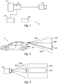
- the figure 1 shows schematically a central digital rearview system according to the invention.
- the digital rearview system 1 comprises a rearview computer 10, a rearview camera 12 and a rearview screen 14.
- the digital rearview system1 is in particular suitable for a motor vehicle such as vehicle 2 of the figure 2 , which includes a tailgate 20.
- the rear view camera 12 is preferably placed in the upper part of the tailgate 20, either inside or outside of the vehicle 2.
- the rear view screen 14 is arranged inside the passenger compartment, 'usual location of the interior rear-view mirror, that is to say in the high and central position of the front windshield of the vehicle, or, preferably, in the central zone of the dashboard, in particular in a position advanced towards the windscreen -broken.
- the digital rearview system 1 is configured to reproduce, on the rearview screen 14, the images captured by the rearview camera 12 and transmitted via the rearview computer 10.
- the rearview computer 10 is connected to a boot opening sensor 16, in the example via a central computer 18 of the vehicle.
- the digital rearview system 1 receives from the boot opening sensor 16 information according to which the tailgate 20 is open.
- the digital rearview system 1 Following reception of this information, the digital rearview system 1 emits an alert signal for the driver and / or performs a corrective action.
- the alert signal can be a light signal, and / or an audible signal, and / or the display of an alert message on the rear view screen 14.
- the emission of an alert signal, especially when it comes to a message alert, can be accompanied or not by the stop of the restitution of the image captured by the rear view camera 12 on the rear view screen 14.
- a corrective action consists in modifying the image reproduced on the rear view screen 14, which is a portion of the image captured by the rear view camera 12.
- This modification can for example consist of a modification of the angle of "Tilt", or tilt angle of the restored image.
- Such a modification is illustrated on the figure 3 , which shows on the left part of the figure, the field of vision of the camera in a vertical plane, and, on the right part, the image captured by the camera.
- the field of vision of the rear view camera 12 makes it possible to obtain a captured image 120, generally in 4/3 or 16/9 format, which is larger than the image which will be reproduced on the rear view screen 14
- the restored image 122 which is displayed on this screen constitutes a portion of the image captured 120 by the camera. It is therefore possible to modify the position, in particular in height, of this portion of image 122 which is restored, as shown on the figure 2 .
- the field of vision is located in the vertical plane of the rear view camera 12 when the trunk is closed (reference 124), when the trunk is opened by an angle of approximately 10 ° (reference 126), and finally the portion of the field of vision corresponding to the portion of image reproduced on the screen (reference 128).
- the field of vision of the rear view camera 12 is shifted upward relative to the normal field of vision (tailgate closed).
- the modification of the "tilt" angle makes it possible to compensate for this offset, by lowering, within the image captured 120 by the camera, the portion of this image which will be restored to the driver.
- the corrective action consisting in modifying the angle of inclination of the restored image 122 can be carried out automatically by the digital rearview system 1, for example by detection and compensation of the position of the horizon within the image returned 122 to the driver.
- this compensation will be carried out according to predetermined rules, for example a rule implying to maintain the position of the horizon at a given level of the restored image (for example to maintain a 1: 3 ratio between the portion of the restored image corresponding to the sky and the portion of the restored image corresponding to the ground).
- this modification action can be carried out by the driver.
- the system is in this case equipped with an adjustment control of the tilt angle, and the system emits an alert signal, in particular an alert message, inviting the driver to make such a modification when the opening of the tailgate is detected.
- the digital rearview system stops displaying the images captured by the camera on the rearview screen, and displays a message relating to the non availability of the system.
- the driver will have the choice between digital rear view and conventional rear view.
- the driver will retain the possibility of using the rearview mirror.
Landscapes
- Engineering & Computer Science (AREA)
- Multimedia (AREA)
- Mechanical Engineering (AREA)
- Fittings On The Vehicle Exterior For Carrying Loads, And Devices For Holding Or Mounting Articles (AREA)
- Closed-Circuit Television Systems (AREA)
Abstract
Description
- L'invention se rapporte au domaine des équipements et systèmes de vision équipant les véhicules automobiles. Plus précisément, l'invention concerne les systèmes de rétrovision intérieurs.
- La législation impose, pour la plupart de véhicules automobiles, la présence de rétroviseurs. Par exemple, les voitures particulières doivent disposer au minimum d'un rétroviseur intérieur et, selon les cas, d'un ou deux rétroviseurs extérieurs. Les rétroviseurs doivent être composés de miroirs plans ou sphériques convexes. Le rétroviseur intérieur doit permettre au conducteur de voir, à travers la lunette arrière du véhicule, au moins une portion de route, centrée sur le plan longitudinal médian du véhicule, ayant une certaine largeur et s'étendant d'une certaine distance de l'arrière du véhicule à l'infini.
- Une évolution récente de la législation permet désormais que le miroir rétroviseur intérieur soit remplacé par un système de rétrovision numérique, comportant une caméra située à l'arrière du véhicule et orientée vers l'arrière, et un dispositif pour l'affichage des images fournies par la caméra.
- Un tel système peut toutefois présenter des défaillances lorsqu'il est monté sur un véhicule équipé d'un hayon. En effet, la caméra étant alors fixée sur le hayon, l'ouverture de celui-ci a pour effet de faire pivoter la caméra et donc de modifier son orientation, le champ de vision de la caméra étant alors affecté. Cette modification du champ de vision de la caméra est susceptible d'induire le conducteur en erreur. Or, il faut envisager que le véhicule puisse rouler avec le hayon ouvert, par exemple en cas de transport d'une charge longue.
- Il existe donc un besoin de prévoir un système de rétrovision numérique qui puisse rester fiable en toutes circonstances, en particulier si le hayon du véhicule est ouvert.
- L'invention a pour objet de répondre à ce besoin.
- À cet effet, l'invention concerne un procédé de rétrovision numérique pour un véhicule automobile comportant un hayon et une caméra de rétrovision fixée au hayon, le procédé comportant les étapes suivantes :
- capter une image, ci-après image captée, d'une partie de l'environnement du véhicule au moyen de la caméra de rétrovision ;
- restituer une portion de l'image captée, ci-après image restituée, sur un écran de rétrovision ;
- effectuer une action corrective et/ou émettre un signal d'alerte si le hayon est ouvert.
- Ainsi, le procédé conforme à l'invention permet de prendre en compte l'état ouvert ou fermé du hayon, afin d'éviter une restitution non conforme de l'environnement du véhicule lorsque le hayon est ouvert et modifie l'orientation de la caméra de rétrovision. Le procédé conforme à l'invention permet de corriger, éventuellement de manière automatique, cette restitution non conforme, et/ou d'avertir le conducteur de celle-ci.
- Dans une réalisation, l'action corrective consiste en une modification de la portion de l'image captée qui est restituée.
- Dans une réalisation, la modification de la portion de l'image captée est réalisée par modification d'un angle d'inclinaison de l'image restituée, ou angle de « tilt ».
- Dans une réalisation, la modification de l'angle d'inclinaison de l'image restituée est réalisée en fonction de la position de l'horizon sur l'image restituée.
- Dans une réalisation, le signal d'alerte est un signal lumineux et/ou un signal sonore et/ou un message d'alerte affiché sur l'écran de rétrovision.
- Dans une réalisation, l'émission d'un signal d'alerte est couplée à l'arrêt de l'affichage de l'image restituée sur l'écran de rétrovision.
- Dans une réalisation, le procédé comporte une étape de détection d'un phénomène vibratoire affectant l'image restituée, une action corrective telle que l'arrêt de l'affichage de l'image restituée pouvant être réalisée si un phénomène vibratoire correspondant à une configuration dans laquelle le hayon est ouvert est détecté.
- L'invention concerne également un produit programme d'ordinateur comprenant des instructions qui, lorsque le programme est exécuté par un processeur, conduisent celui-ci à mettre en oeuvre les étapes du procédé tel que défini ci-dessus.
- L'invention concerne également un système de rétrovision numérique pour la mise en oeuvre d'un procédé tel que défini ci-dessus, le système de rétrovision comportant un calculateur de rétrovision, une caméra de rétrovision, un écran de rétrovision et un capteur d'ouverture de coffre.
- L'invention concerne également un véhicule automobile mettant en oeuvre un procédé tel que défini plus haut, et/ou comportant un système de rétrovision numérique conforme à celui défini ci-dessus.
- La présente invention sera mieux comprise à la lecture de la description détaillée qui suit, faite en référence au dessins annexés, dans lesquels :
- la
figure 1 représente un système de rétrovision numérique pour véhicule automobile configuré pour mettre en oeuvre un procédé conforme à l'invention ; - la
figure 2 représente un véhicule automobile équipé d'un système de rétrovision numérique conforme à l'invention ; - la
figure 3 est un schéma montrant le principe de modification de l'angle d'inclinaison de l'image restituée. - La
figure 1 représente schématiquement un système de rétrovision numérique centrale conforme à l'invention. Le système de rétrovision numérique 1 comporte un calculateur de rétrovision 10, une caméra de rétrovision 12 et un écran de rétrovision 14. Le système de rétrovision numérique1 est notamment adapté à un véhicule automobile tel que le véhicule 2 de lafigure 2 , qui comporte un hayon 20 arrière. La caméra de rétrovision 12 est disposée de préférence en partie haute du hayon 20, soit à l'intérieur soit à l'extérieur du véhicule 2. L'écran de rétrovision 14 est disposé à l'intérieur de l'habitacle, soit à l'emplacement usuel du miroir rétroviseur intérieur, c'est-à-dire en position haute et centrale du pare-brise avant du véhicule, soit, de préférence, en zone centrale de la planche de bord, notamment dans une position avancée vers le pare-brise. Le système de rétrovision numérique 1 est configuré pour restituer, sur l'écran de rétrovision 14, les images captées par la caméra de rétrovision 12 et transmises par l'intermédiaire du calculateur de rétrovision 10. Conformément à l'invention, le calculateur de rétrovision 10 est relié à un capteur d'ouverture de coffre 16, dans l'exemple par l'intermédiaire d'un calculateur central 18 du véhicule. - Ainsi, lorsque le hayon 20 du véhicule 2 est ouvert, ou n'est pas correctement fermé, le système de rétrovision numérique 1 reçoit du capteur d'ouverture de coffre 16 une information selon laquelle le hayon 20 est ouvert.
- Suite à la réception de cette information, le système de rétrovision numérique 1 émet un signal d'alerte à l'attention du conducteur et/ou effectue une action corrective.
- Le signal d'alerte peut être un signal lumineux, et/ou un signal sonore, et/ou l'affichage d'un message d'alerte sur l'écran de rétrovision 14. L'émission d'un signal d'alerte, en particulier lorsqu'il s'agit d'un message d'alerte, peut être accompagné ou non de l'arrêt de la restitution de l'image captée par la caméra de rétrovision 12 sur l'écran de rétrovision 14.
- Une action corrective consiste en la modification de l'image restituée sur l'écran de rétrovision 14, qui est une portion de l'image captée par la caméra de rétrovision 12. Cette modification peut par exemple consister en une modification de l'angle de « tilt », ou angle d'inclinaison de l'image restituée. Une telle modification est illustrée sur la
figure 3 , qui montre sur la partie gauche de la figure, le champ de vision de la caméra dans un plan vertical, et, sur la partie droite, l'image captée par la caméra. Comme visible sur lafigure 3 , le champ de vision de la caméra de rétrovision 12 permet d'obtenir une image captée 120, généralement au format 4/3 ou 16/9, qui est plus grande que l'image qui va être restituée sur l'écran de rétrovision 14. Ainsi l'image restituée 122 qui est affichée sur cet écran constitue une portion de l'image captée 120 par la caméra. Il est donc possible de modifier la position, notamment en hauteur, de cette portion d'image 122 qui est restituée, comme montré sur lafigure 2 . - Sur la
figure 2 est repéré le champ de vision dans le plan vertical de la caméra de rétrovision 12 lorsque le coffre est fermé (référence 124), lorsque le coffre est ouvert d'un angle d'environ 10° (référence 126), et enfin la portion du champ de vision correspondant à la portion d'image restituée sur l'écran (référence 128). Comme visible sur lafigure 2 , lorsque le hayon du véhicule 2 est ouvert, le champ de vision de la caméra de rétrovision 12 se trouve décalé vers le haut par rapport au champ de vision normal (hayon fermé). Toutefois, la modification de l'angle de « tilt » permet de compenser ce décalage, en abaissant, au sein de l'image captée 120 par la caméra, la portion de cette image qui va être restituée au conducteur. - L'action corrective consistant à modifier l'angle d'inclinaison de l'image restituée 122 peut être effectuée automatiquement par le système de rétrovision numérique 1, par exemple par détection et compensation de la position de l'horizon au sein de l'image restituée 122 au conducteur. Dans ce cas, cette compensation sera effectuée en fonction de règles prédéterminées, par exemple une règle impliquant de maintenir la position de l'horizon à un niveau donné de l'image restituée (par exemple pour maintenir un rapport de 1 : 3 entre la portion de l'image restituée correspondant au ciel et la portion de l'image restituée correspondant au sol).
- Alternativement, cette action de modification peut être réalisée par le conducteur. Le système est dans ce cas équipé d'une commande de réglage de l'angle de « tilt », et le système émet un signal d'alerte, notamment un message d'alerte, invitant le conducteur à effectuer une telle modification lorsque l'ouverture du hayon est détectée.
- On pourra également prévoir de détecter, au moyen d'un algorithme de traitement de l'image captée par la caméra de rétrovision, un phénomène de vibration lié à la mauvaise fixation du hayon en position ouverte. En effet, dans un tel cas, l'image est susceptible de vibrer en même temps que le volet du hayon, ce qui peut être extrêmement désagréable pour le conducteur. On pourra alors prévoir que, sur détection d'un tel phénomène vibratoire, le système de rétrovision numérique arrête l'affichage des images captées par la caméra sur l'écran de rétrovision, et affiche à l'attention du conducteur un message relatif à la non disponibilité du système.
- On pourra prévoir que le système de rétrovision numérique conforme à l'invention, et en particulier l'écran de rétrovision, soit compatible avec un miroir de rétrovision centrale classique. Ainsi, en prévoyant par exemple que l'écran de rétrovision soit intégré à un miroir de rétrovision, le conducteur pourra avoir le choix entre la rétrovision numérique et la rétrovision conventionnelle. Ainsi, en cas de non disponibilité du système de rétrovision numérique, le conducteur conservera la possibilité d'utiliser le miroir de rétrovision.
Claims (10)
- Procédé de rétrovision numérique pour un véhicule (2) automobile comportant un hayon (20) et une caméra de rétrovision (12) fixée au hayon, le procédé comportant les étapes suivantes :- capter une image, ci-après image captée (120), d'une partie de l'environnement du véhicule au moyen de la caméra de rétrovision (12) ;- restituer une portion de l'image captée, ci-après image restituée (122), sur un écran de rétrovision (14) ;- effectuer une action corrective et/ou émettre un signal d'alerte si le hayon (20) est ouvert.
- Procédé selon la revendication précédente, dans lequel l'action corrective consiste en une modification de la portion de l'image captée (120) qui est restituée.
- Procédé selon la revendication précédente, dans lequel la modification de la portion de l'image captée (120) est réalisée par modification d'un angle d'inclinaison de l'image restituée (122), ou angle de « tilt ».
- Procédé selon la revendication précédente, dans lequel la modification de l'angle d'inclinaison de l'image restituée (122) est réalisée en fonction de la position de l'horizon sur l'image restituée (122).
- Procédé selon l'une des revendications précédentes, dans lequel le signal d'alerte est un signal lumineux et/ou un signal sonore et/ou un message d'alerte affiché sur l'écran de rétrovision (14).
- Procédé selon la revendication précédente, dans lequel l'émission d'un signal d'alerte est couplée à l'arrêt de l'affichage de l'image restituée (122) sur l'écran de rétrovision (14).
- Procédé selon l'une des revendications précédentes, comportant une étape de détection d'un phénomène vibratoire affectant l'image restituée (122), une action corrective telle que l'arrêt de l'affichage de l'image restituée (122) pouvant être réalisée si un phénomène vibratoire correspondant à une configuration dans laquelle le hayon (20) est ouvert est détecté.
- Produit programme d'ordinateur comprenant des instructions qui, lorsque le programme est exécuté par un processeur, conduisent celui-ci à mettre en oeuvre les étapes du procédé selon l'une des revendications 1 à 7.
- Système de rétrovision numérique (1) pour la mise en oeuvre d'un procédé conforme à l'une des revendications 1 à 7, le système de rétrovision comportant un calculateur de rétrovision (10), une caméra de rétrovision (12), un écran de rétrovision (14) et un capteur d'ouverture de coffre (16).
- Véhicule (2) automobile mettant en oeuvre un procédé conforme à l'une des revendications 1 à 7 et/ou comportant un système de rétrovision numérique (1) conforme à la revendication 9.
Applications Claiming Priority (1)
| Application Number | Priority Date | Filing Date | Title |
|---|---|---|---|
| FR1858464A FR3085910A1 (fr) | 2018-09-19 | 2018-09-19 | Procede et systeme de retrovision numerique pour un vehicule automobile |
Publications (1)
| Publication Number | Publication Date |
|---|---|
| EP3626537A1 true EP3626537A1 (fr) | 2020-03-25 |
Family
ID=65201526
Family Applications (1)
| Application Number | Title | Priority Date | Filing Date |
|---|---|---|---|
| EP19194891.8A Withdrawn EP3626537A1 (fr) | 2018-09-19 | 2019-09-02 | Procédé et système de rétrovision numérique pour un véhicule automobile |
Country Status (3)
| Country | Link |
|---|---|
| EP (1) | EP3626537A1 (fr) |
| CN (1) | CN110920522A (fr) |
| FR (1) | FR3085910A1 (fr) |
Cited By (1)
| Publication number | Priority date | Publication date | Assignee | Title |
|---|---|---|---|---|
| US11639154B1 (en) | 2021-10-11 | 2023-05-02 | Toyota Motor Engineering & Manufacturing North America, Inc. | Systems and methods to detect tailgate removal using alarm circuits |
Citations (8)
| Publication number | Priority date | Publication date | Assignee | Title |
|---|---|---|---|---|
| US20140071279A1 (en) * | 2012-09-10 | 2014-03-13 | Nissan North America, Inc. | Vehicle video system |
| US20150183380A1 (en) * | 2013-12-31 | 2015-07-02 | Huf North America Automotive Parts Mfg. Corp. | Multi-Positioning of a Camera or Other Sensing Device |
| US20160119539A1 (en) * | 2014-10-28 | 2016-04-28 | Nissan North America, Inc. | Vehicle object monitoring system |
| WO2017025681A1 (fr) * | 2015-08-11 | 2017-02-16 | Peugeot Citroen Automobiles Sa | Système d'aide a la conduite pour un véhicule pourvu d'un système de rétrovision numérique adaptable pour manoeuvre de recul |
| US9669771B1 (en) * | 2016-02-19 | 2017-06-06 | Toyota Motor Engineering & Manufacturing North America, Inc. | Gravity mount and rotational securement for sensing element |
| US20180086283A1 (en) * | 2016-09-26 | 2018-03-29 | Panasonic Automotive Systems Company Of America, Division Of Panasonic Corporation Of North America | Swivel tailgate bracket |
| WO2018079357A1 (fr) * | 2016-10-26 | 2018-05-03 | パナソニックIpマネジメント株式会社 | Appareil à miroir électronique |
| WO2018094153A1 (fr) * | 2016-11-18 | 2018-05-24 | Huf North America Automotive Parts Mfg. Corp. | Ensemble capteur déployable |
Family Cites Families (6)
| Publication number | Priority date | Publication date | Assignee | Title |
|---|---|---|---|---|
| JPH0880791A (ja) * | 1994-09-13 | 1996-03-26 | Trans Tron:Kk | 車載用後方確認装置 |
| JP2000032322A (ja) * | 1998-06-23 | 2000-01-28 | Hewlett Packard Co <Hp> | 画像捕捉システム |
| JP4681856B2 (ja) * | 2004-11-24 | 2011-05-11 | アイシン精機株式会社 | カメラの校正方法及びカメラの校正装置 |
| US20110128350A1 (en) * | 2009-11-30 | 2011-06-02 | Motorola, Inc. | Method and apparatus for choosing a desired field of view from a wide-angle image or video |
| JP6458439B2 (ja) * | 2014-10-09 | 2019-01-30 | 株式会社デンソー | 車載カメラ較正装置、画像生成装置、車載カメラ較正方法、画像生成方法 |
| EP3176035A1 (fr) * | 2015-12-03 | 2017-06-07 | Fico Mirrors S.A. | Système de vision arrière pour véhicule automobile |
-
2018
- 2018-09-19 FR FR1858464A patent/FR3085910A1/fr not_active Withdrawn
-
2019
- 2019-09-02 EP EP19194891.8A patent/EP3626537A1/fr not_active Withdrawn
- 2019-09-19 CN CN201910884877.4A patent/CN110920522A/zh active Pending
Patent Citations (8)
| Publication number | Priority date | Publication date | Assignee | Title |
|---|---|---|---|---|
| US20140071279A1 (en) * | 2012-09-10 | 2014-03-13 | Nissan North America, Inc. | Vehicle video system |
| US20150183380A1 (en) * | 2013-12-31 | 2015-07-02 | Huf North America Automotive Parts Mfg. Corp. | Multi-Positioning of a Camera or Other Sensing Device |
| US20160119539A1 (en) * | 2014-10-28 | 2016-04-28 | Nissan North America, Inc. | Vehicle object monitoring system |
| WO2017025681A1 (fr) * | 2015-08-11 | 2017-02-16 | Peugeot Citroen Automobiles Sa | Système d'aide a la conduite pour un véhicule pourvu d'un système de rétrovision numérique adaptable pour manoeuvre de recul |
| US9669771B1 (en) * | 2016-02-19 | 2017-06-06 | Toyota Motor Engineering & Manufacturing North America, Inc. | Gravity mount and rotational securement for sensing element |
| US20180086283A1 (en) * | 2016-09-26 | 2018-03-29 | Panasonic Automotive Systems Company Of America, Division Of Panasonic Corporation Of North America | Swivel tailgate bracket |
| WO2018079357A1 (fr) * | 2016-10-26 | 2018-05-03 | パナソニックIpマネジメント株式会社 | Appareil à miroir électronique |
| WO2018094153A1 (fr) * | 2016-11-18 | 2018-05-24 | Huf North America Automotive Parts Mfg. Corp. | Ensemble capteur déployable |
Cited By (1)
| Publication number | Priority date | Publication date | Assignee | Title |
|---|---|---|---|---|
| US11639154B1 (en) | 2021-10-11 | 2023-05-02 | Toyota Motor Engineering & Manufacturing North America, Inc. | Systems and methods to detect tailgate removal using alarm circuits |
Also Published As
| Publication number | Publication date |
|---|---|
| CN110920522A (zh) | 2020-03-27 |
| FR3085910A1 (fr) | 2020-03-20 |
Similar Documents
| Publication | Publication Date | Title |
|---|---|---|
| FR3045177A1 (fr) | Procede de controle d'une fonctionnalite d'un vehicule automobile au moyen d'un terminal mobile | |
| EP3632388B1 (fr) | Dispositif électronique de pilotage d'une rampe d'accès à une porte de véhicule, véhicule, procédé de pilotage et programme d'ordinateur associés | |
| FR3067309A1 (fr) | Procede et systeme de reglage automatique d'au moins un equipement d'un vehicule automobile | |
| EP4374340A1 (fr) | Procédé et dispositif de contrôle d'ouverture de porte de véhicule | |
| WO2008043931A1 (fr) | Procede et dispositif de commande d'un ouvrant motorise de vehicule automobile | |
| FR3085910A1 (fr) | Procede et systeme de retrovision numerique pour un vehicule automobile | |
| EP3627467B1 (fr) | Procédé et dispositif de détection de l état d'un capot avant d'un véhicule automobile par comparaison de champs de vision | |
| EP3867126B1 (fr) | Procédé et dispositif d'aide à la conduite d'un véhicule automobile en phase de recul | |
| FR3146639A1 (fr) | Procédé et dispositif de contrôle d’ouverture de porte de véhicule en fonction de données de capteurs arrière du véhicule | |
| FR3074328B1 (fr) | Procede d'activation d'au moins une fonction d'un equipement d'un vehicule | |
| EP3571466B1 (fr) | Procédé et dispositif autonomes de détermination d'une assiette d'un véhicule automobile | |
| EP4041606B1 (fr) | Détermination d'un état d'utilisateur conduisant activement ou non un véhicule automobile | |
| FR3056501A1 (fr) | Systeme d'aide a l'identification d'un vehicule automobile et son procede de mise en oeuvre | |
| EP3169575A1 (fr) | Procede de commande de la position angulaire du volant d'un vehicule et vehicule associe | |
| FR3040029A1 (fr) | Systeme d’aide a la conduite pour un vehicule pourvu d’un systeme de retrovision numerique adaptable pour manoeuvre de recul | |
| FR3113390A1 (fr) | Procédé de détermination de la posture d’un conducteur | |
| FR3108286A1 (fr) | Système et dispositif d’affichage d’informations pour véhicule basé sur des profils d’affichage | |
| FR2941307A1 (fr) | Systeme d'affichage d'informations notamment pour vehicule automobile et vehicule automobile comportant un tel systeme d'affichage. | |
| FR3063357A1 (fr) | Dispositif d'affichage d'informations dans un habitacle de vehicule automobile | |
| FR3133352A1 (fr) | Procédé et dispositif de contrôle du champ de vision d’au moins une caméra d’un système de rétrovision numérique d’un véhicule en stationnement | |
| FR3149261A1 (fr) | Procédé et dispositif de contrôle d’un ensemble de rétroviseurs extérieurs d’un d’un véhicule | |
| FR3132780A1 (fr) | Procédé de calibration d’un dispositif de rétrovision numérique latérale extérieure d’un véhicule automobile | |
| FR3154679A1 (fr) | Procédé implémenté par ordinateur pour l’installation d’un balai d'essuie-glace | |
| FR3140157A1 (fr) | Procédé et dispositif de mesure de la longueur d’un d’objet dépassant de l’arrière d’un véhicule automobile | |
| FR3154671A1 (fr) | Système et procédé d’affichage enrichi pour véhicule automobile |
Legal Events
| Date | Code | Title | Description |
|---|---|---|---|
| PUAI | Public reference made under article 153(3) epc to a published international application that has entered the european phase |
Free format text: ORIGINAL CODE: 0009012 |
|
| STAA | Information on the status of an ep patent application or granted ep patent |
Free format text: STATUS: THE APPLICATION HAS BEEN PUBLISHED |
|
| AK | Designated contracting states |
Kind code of ref document: A1 Designated state(s): AL AT BE BG CH CY CZ DE DK EE ES FI FR GB GR HR HU IE IS IT LI LT LU LV MC MK MT NL NO PL PT RO RS SE SI SK SM TR |
|
| AX | Request for extension of the european patent |
Extension state: BA ME |
|
| STAA | Information on the status of an ep patent application or granted ep patent |
Free format text: STATUS: REQUEST FOR EXAMINATION WAS MADE |
|
| 17P | Request for examination filed |
Effective date: 20200915 |
|
| RBV | Designated contracting states (corrected) |
Designated state(s): AL AT BE BG CH CY CZ DE DK EE ES FI FR GB GR HR HU IE IS IT LI LT LU LV MC MK MT NL NO PL PT RO RS SE SI SK SM TR |
|
| GRAP | Despatch of communication of intention to grant a patent |
Free format text: ORIGINAL CODE: EPIDOSNIGR1 |
|
| STAA | Information on the status of an ep patent application or granted ep patent |
Free format text: STATUS: GRANT OF PATENT IS INTENDED |
|
| RAP1 | Party data changed (applicant data changed or rights of an application transferred) |
Owner name: PSA AUTOMOBILES SA |
|
| INTG | Intention to grant announced |
Effective date: 20201030 |
|
| RIN1 | Information on inventor provided before grant (corrected) |
Inventor name: VRINAT, DAVID Inventor name: RIAT, JEAN CHRISTOPHE Inventor name: FEINGOLD, LAURENT |
|
| STAA | Information on the status of an ep patent application or granted ep patent |
Free format text: STATUS: THE APPLICATION IS DEEMED TO BE WITHDRAWN |
|
| 18D | Application deemed to be withdrawn |
Effective date: 20210310 |