EP3626137A1 - Dispositif d'agitation rotatif de machine de préparation de boissons équipe d'un dispositif d'accouplement magnétique - Google Patents
Dispositif d'agitation rotatif de machine de préparation de boissons équipe d'un dispositif d'accouplement magnétique Download PDFInfo
- Publication number
- EP3626137A1 EP3626137A1 EP19196988.0A EP19196988A EP3626137A1 EP 3626137 A1 EP3626137 A1 EP 3626137A1 EP 19196988 A EP19196988 A EP 19196988A EP 3626137 A1 EP3626137 A1 EP 3626137A1
- Authority
- EP
- European Patent Office
- Prior art keywords
- drive shaft
- stirring device
- tubular part
- rotary stirring
- rotary
- Prior art date
- Legal status (The legal status is an assumption and is not a legal conclusion. Google has not performed a legal analysis and makes no representation as to the accuracy of the status listed.)
- Granted
Links
Images



Classifications
-
- A—HUMAN NECESSITIES
- A47—FURNITURE; DOMESTIC ARTICLES OR APPLIANCES; COFFEE MILLS; SPICE MILLS; SUCTION CLEANERS IN GENERAL
- A47J—KITCHEN EQUIPMENT; COFFEE MILLS; SPICE MILLS; APPARATUS FOR MAKING BEVERAGES
- A47J43/00—Implements for preparing or holding food, not provided for in other groups of this subclass
- A47J43/04—Machines for domestic use not covered elsewhere, e.g. for grinding, mixing, stirring, kneading, emulsifying, whipping or beating foodstuffs, e.g. power-driven
- A47J43/07—Parts or details, e.g. mixing tools, whipping tools
- A47J43/0705—Parts or details, e.g. mixing tools, whipping tools for machines with tools driven from the upper side
- A47J43/0711—Parts or details, e.g. mixing tools, whipping tools for machines with tools driven from the upper side mixing, whipping or cutting tools
-
- A—HUMAN NECESSITIES
- A47—FURNITURE; DOMESTIC ARTICLES OR APPLIANCES; COFFEE MILLS; SPICE MILLS; SUCTION CLEANERS IN GENERAL
- A47J—KITCHEN EQUIPMENT; COFFEE MILLS; SPICE MILLS; APPARATUS FOR MAKING BEVERAGES
- A47J31/00—Apparatus for making beverages
- A47J31/44—Parts or details or accessories of beverage-making apparatus
- A47J31/4489—Steam nozzles, e.g. for introducing into a milk container to heat and foam milk
Definitions
- the present invention relates to beverage dispensing devices which comprise a rotary stirring device with hot water and / or steam distribution, in particular machines for preparing beverages based on hot or cold frothed milk (cappuccino, latte, chocolate, cocktail ...) or made with whipped cream (special coffees and chocolate).
- machines for preparing beverages which include in particular a rotary stirring device, which comprises a rotary tool about a vertical axis and intended to stir a preparation contained in a container and a conduit for hot water and / or steam towards the rotary tool so as to dilute and / or reheat the said preparation in the container by foaming it.
- a rotary stirring device which comprises a rotary tool about a vertical axis and intended to stir a preparation contained in a container and a conduit for hot water and / or steam towards the rotary tool so as to dilute and / or reheat the said preparation in the container by foaming it.
- the conveying duct comprises a tubular part which extends along the vertical axis between a first end which is coupled to the rotary tool and a second end which is removably coupled to a drive shaft at the by means of a coupling device.
- the possibility of dismantling the tubular part with the rotary tool facilitates their cleaning under water or in a dishwasher.
- the coupling device used in this patent application EP2721980A1 has various disadvantages. Indeed, the assembly and withdrawal of the tubular part vis-à-vis the drive shaft require manipulation of the coupling device, which is not intuitive. During assembly, the user may incorrectly engage the coupling device; during rotation, the tubular part may inadvertently detach from the drive shaft. In addition, the pressure of hot water and / or steam inside the tubular part can generate leaks at the coupling device.
- the present invention overcomes the aforementioned drawbacks.
- the invention relates to a rotary stirring device of a beverage preparation machine.
- the rotary stirring device comprises a rotary tool around an axis A and intended to stir a preparation contained in a container, for example milk.
- the rotary stirring device also includes a conduit for routing hot water and / or steam to the rotary tool.
- This routing conduit comprises a hollow part of a drive shaft which communicates with a tubular part which extends along the axis A between a first end which is coupled to the rotary tool by means of a first coupling device and a second end which is coupled to said hollow part of the drive shaft by means of a second coupling device, which allows a fluid connection of hot water and / or steam.
- hot water and / or steam circulates in the hollow part of the drive shaft and then in the tubular part which is coupled to said drive shaft.
- the second coupling device is a magnetic coupling device configured to generate a magnetic attraction force along the axis A between the drive shaft and the second end of the tubular part, so as to transmit the rotational movement from the drive shaft to the rotary tool.
- the magnetic coupling device comprises a metal member arranged on the second end of the tubular part and formed by an internal ring made of stainless steel resistant to corrosion in a vapor environment and an external ring made of a ferromagnetic material. During the coupling of the tubular part on the drive shaft, this internal ring is intended to slide on the hollow part which is also made of stainless steel resistant to corrosion in a vapor environment.
- the use of such a metallic member allows advantageously to reduce wear by bringing the inner ring into contact with the hollow part of the drive shaft. This increases the life of the tubular part receiving the rotary tool.
- the coupling of the tubular part with the drive shaft is done simply by fitting them one into the other, without any additional manipulation, the magnetic coupling device then ensuring a magnetic attraction force favoring said fitting until the tubular part reaches an abutment position with respect to the drive shaft, an abutment position in which said elements are coupled.
- This stop position indicates to the user that the coupling is carried out properly.
- the withdrawal of the tubular part with the rotary tool is carried out simply by exerting a tensile force on said tubular part, greater than the magnetic attraction force, which releases it from the drive shaft.
- the rotation of the drive shaft generates that of the tubular part and of the rotary tool, by means of the magnetic coupling device which makes it possible to secure said elements.
- the first coupling device between the first end of the tubular part and the rotary tool can be of very varied designs.
- the first coupling device can ensure permanent mounting between the first end and the rotary tool so that they are difficult to dismantle or not at all, for example by making the tubular part and the rotary tool by means of '' one and the same piece or by assembling the tubular part and the rotary tool by means of fixing screws or gluing.
- this first coupling device can provide a removable mounting between the first end and the rotary tool, for example by means of a bayonet assembly system or a fitting between said elements. Disassembly of the rotary tool vis-à-vis the first end of the tubular part will be preferable in order to allow their cleaning independently or the change of rotary tool, for example.
- the internal ring is tightly mounted in the external ring. This allows the inner ring and the outer ring to be secured by means of these two rings alone, without any parts complementary, so as to guarantee a coupling without sliding between said rings.
- securing means between the inner ring and the outer ring could consider variants of securing means between the inner ring and the outer ring.
- the second end of the tubular part is made of a plastic material which surrounds an outer face of the outer ring.
- the second end of the tubular part is molded onto the outer walls of the outer ring. This allows the metal member to be fixed on the second end of the tubular part, while isolating said outer ring from the outside in order to protect it against corrosion.
- the hollow part of the drive shaft has an external diameter D and the internal ring has a height H.
- the height H is greater than the diameter D.
- the height H is five times greater than diameter D. This provides good control over the rotation and guiding of the tubular part with the rotary tool, despite the radial forces exerted on said rotary tool during the agitation of the preparation contained in the container.
- the hollow part of the drive shaft has a groove provided with a seal which is arranged opposite the internal ring when the tubular part is coupled to the training tree.
- the drive shaft comprises a magnetic element formed by a permanent magnet which generates a magnetic attraction force on the metallic member and which tends to press a driving wall of the shaft d drive against a receiving wall of the second end of the tubular part to transmit the rotational movement of the drive shaft to the tubular part.
- the driving wall of the drive shaft and the receiving wall of the second end of the tubular part each extend in a plane perpendicular to the axis A. This makes it possible to increase the surface of contact and magnetic attraction between the motor wall and the receiving wall.
- the rotary stirring device comprises a device for detecting the presence of the tubular part on the drive shaft.
- the tubular part has a protrusion in diameter at the level of the magnetic or magnetizable element which cuts a beam from said detection device when said tubular part is assembled on the drive shaft.
- the detection device is an optical detection device comprising a cell emitting a light beam and a cell receiving said beam, the tubular part cutting the light beam when it is assembled on the drive shaft.
- the optical detection device comprises at least one optical guide for returning the light beam at 90 °.
- the detection of the presence of the rotary tool also makes it possible to know whether the user has removed or not the rotary tool at the end of the recipe, which makes it possible for example to program the beverage preparation machine to manage the cleaning of the rotary tool after a defined number of beverage preparations by means of said rotary tool, for example by emitting an audible or visual signal of information on cleaning the rotary tool to be produced.
- the second coupling device comprises a system of mechanical anti-slip stops which ensures automatic alignment between the drive shaft and the second end of the tubular part, during the coupling under the effect of the magnetic attraction force.
- the presence of such a system of mechanical anti-slip stops ensures self-positioning when the second end of the tubular part is coupled with the drive shaft, under the sole action of the magnetic attraction force. exerted by the magnetic coupling device.
- this anti-slip mechanical stop system avoids any risk of rotation along the axis A between the drive shaft and the tubular part, due in particular to the resistance exerted on the rotary tool which rotates in the preparation. food contained in the container.
- the mechanical stop system includes at least one prominent drive member arranged on a drive wall of the shaft.
- drive and at least one receiving housing arranged on a receiving wall of the second end of the tubular part, the at least one prominent driving member, once in place in the at least one receiving housing, ensuring a positive drive - that is to say without sliding - of the rotary tool.
- the at least one prominent drive member comprises a propeller-shaped ramp arranged on a center circle belonging to the axis A, the at least one receiving housing having a complementary shape.
- the outer ring has a thickness E1 greater than 0.5mm, preferably greater than 1mm.
- the internal ring has a thickness E2 greater than 0.5mm, preferably greater than 1mm.
- the rotary stirring device comprises an electric motor intended to drive the drive shaft.
- the rotary stirring device comprises a steam box comprising a chamber, a radial steam inlet channel, two sealed bearings for guiding the drive shaft.
- the hollow part of the drive shaft is configured to connect the chamber to the tubular part so as to convey the hot water and / or the steam.
- machine the beverage preparation machine
- the machine 1 comprises in particular a frame 2, a support 3 on which a container 4 can be placed during the preparation of a drink, and a dispensing device which comprises in particular a nozzle 5 allowing the distribution of a drink based on coffee, tea and / or chocolate, for example.
- a dispensing device which comprises in particular a nozzle 5 allowing the distribution of a drink based on coffee, tea and / or chocolate, for example.
- the machine 1 also comprises a rotary stirring device 6 comprising a rotary tool 7 around an axis A and intended to stir a preparation contained in the container 4, for example milk.
- This axis A is defined vertically on the machine 1.
- the rotary stirring device 6 is mounted in translation along the axis A, inside a guide piece 8 arranged on the frame 2, so as to allow its displacement in a high position illustrated in figure 1 , where the rotary tool 7 is released from the container 4, and a low position illustrated in figure 2 , where the rotary tool 7 is inserted into the container 4.
- the rotary stirring device 6 comprises a body 9 mounted in translation along the axis A on the guide piece 8 illustrated in Figures 1 and 2 , by means of slides (not shown). Inside the body 9 are arranged an electric motor 10 and a steam box 11.
- the electric motor 10 drives in rotation about the axis A a drive shaft 12, which is mounted in pivot connection of axis A screw -with respect to the steam box 11 by means of two sealed rolling bearings 13, 14; the seal implemented between the steam box 11, the bearings 13, 14 and the drive shaft 12 making it possible to define a chamber 15.
- a radial channel crosses the steam box 11 and opens into the chamber 15, this radial channel being connected to a flexible duct (not shown) which allows the movements in translation along the axis A of the rotary stirring device 6 with respect to the guide piece 8, without constraint.
- the flexible conduit supplies hot water and / or steam to the chamber 15.
- the drive shaft 12 has a hollow part 18 extending along the axis A and opening on one side into the chamber 15 through an orifice 16 passing through said hollow part 18 and, on the other side, on the lower end 19 of the drive shaft 12.
- the rotary stirring device 6 comprises a tubular part 20 which extends along the axis A and passes through a bottom 21 (illustrated in Figures 1 and 2 ) of the guide piece 8.
- the lower end 22 of the tubular part 20 is assembled with the rotary tool 7, preferably by interlocking or by means of a bayonet connection.
- the upper end 23 of the tubular part 20 is detachably coupled with the drive shaft 12.
- the flexible channel, the radial duct, the chamber 15, the hollow part 18 of the drive shaft 12 and the tubular part 20 define a conduit 24 for routing hot water and / or steam to the rotary tool 7.
- the coupling of the upper end 23 of the tubular part 20 with the drive shaft 12 is brought into works by means of a magnetic coupling device 25.
- This magnetic coupling device 25 uses a magnetic attraction force in the direction of the axis A, between a driving wall 26 of the shaft d drive 12 and a receiving wall 27 of the upper end 23 of the tubular part 20, these driving walls 26 and receiving 27 extending in planes perpendicular to the axis A.
- This magnetic attraction force makes it possible to press the receiving wall 27 against the driving wall 26 so as to keep the upper end 23 of the tubular part 20 assembled with the drive shaft 12 and to cause the rotation of the receiving wall 27 under the action of the rotation of the driving wall 26.
- the magnetic coupling device 25 comprises a support piece 28 which has the drive wall 26 on its underside 28a, this support piece 28 being forcibly fitted onto the drive shaft 12 so that said support piece 28 and said drive shaft 12 are secured and form an assembly.
- the magnetic coupling device 25 comprises a permanent magnet 29 which has a tubular shape, as illustrated in figure 3 , this permanent magnet 29 being housed inside the support piece 28 prior to its fitting into force on the drive shaft 12 which passes through said permanent magnet 29.
- Rotational locking means are provided between the support piece 28 and the permanent magnet 29 so as to avoid rotation of the permanent magnet 29 along the axis A, inside the support piece 28. For example, may provide a force fit of the permanent magnet 29 in the support piece.
- the coupling device 25 comprises a metal member consisting of an insert 30 which has a tubular shape, as illustrated by the figures 3 and 7 .
- the insert 30 comprises an outer ring 31 and an inner ring 32 which are force-fitted into one another to form a single piece (the insert 30).
- the outer ring 31 is made of a ferromagnetic material and the inner ring 32 is made of a stainless steel resistant to corrosion in a vapor environment. This inner ring 32 is slidably mounted on the drive shaft 12.
- the outer ring 31 is made of 420 or 430 ferromagnetic stainless steel and the inner ring 32 is made of stainless steel 304. Thanks to the overmolding of the end upper 23 of the tubular part 20 on the insert 30, the outer ring 31 is completely coated with the material - a polymer - of said upper end 23, which protects said outer ring 31 against corrosion.
- a seal 33 is housed in a groove 53 arranged on the drive shaft 12 and comes into contact with the internal wall 34 of the internal ring 32 when the receiving wall 27 is pressed against the drive wall 26.
- the injection of hot water and / or steam can cause a pressure rise in the conveying conduit 24; the seal implemented by means of the seal 33 avoids any risk of hot water and / or steam leakage at the connection between the tubular part 20 and the drive shaft 12.
- the internal wall 34 of the internal ring 32 comes into contact with the external wall 54 of the hollow part 18 of the drive shaft 12.
- This external wall 54 has an external diameter D which is very slightly less than the internal diameter D1 of the internal wall 34 - a few microns - so as to produce a sliding assembly of the internal ring 32 on said hollow portion 18.
- the internal ring 32 has a height H which is greater than the external diameter D to ensure proper control of the rotation of the tubular part 20 with the rotary tool 7 and suitable guidance of the upper end 23 of the tubular part when it is coupled with the drive shaft 12.
- the height H is at least five times greater than the external diameter D.
- the outer ring 31 has a thickness E1 greater than 0.5mm, preferably greater than 1mm in order to have a sufficient magnetizing surface to carry out the magnetic attraction by the permanent magnet 29.
- the inner ring 32 has a thickness E2 greater than 0.5mm, preferably greater than 1mm so as to avoid deformation of the inner ring 32 when it is force-fitted into the outer ring 31.
- a groove 55 is implemented on the external contour 31a of the external ring 31 in order to improve the anchoring of the insert 30 in the upper end 23 of the tubular part 20 during overmolding.
- the drive wall 26 comprises four prominent members 35 in the form of helical ramps uniformly distributed around a center circle passing through the axis A.
- the receiving wall 27 comprises, in turn, four housings 36 having a shape complementary to that of the four prominent bodies 35.
- the number of prominent bodies 35 and housings 36 could be different, for example three.
- the permanent magnet 29 exerts a magnetic attraction force on the insert 30, which attracts the receiving wall 27 towards the drive wall 26, the prominent members 35 being housed at least partially respectively in the housings 36; the helical shape of the prominent members 35 and of the housings 36 and the magnetic attraction force then ensure self-positioning of said prominent members 35 in said housings 36 until the receiving wall 27 comes fully into abutment against the driving wall 26 where said elements are self-aligned.
- the ends 35a of the prominent members 35 abut against the ends 36a of the housings 36, which ensures a positive drive of the tubular part 20.
- the prominent members 35 and the housings 36 use a system of mechanical anti-slip stops which ensures automatic alignment between the drive wall 26 and the receiving wall 27.
- the rotary stirring device 6 comprises a detection device 38 which makes it possible to detect the coupling of the upper end 23 of the tubular part 20 with the drive shaft 12 thanks to said magnetic coupling device 25.
- the detection device 38 comprises a cell 39 emitting a light beam, preferably an infrared optical transmitter which has the advantage of being not very sensitive to outside light.
- the detection device 38 also comprises a cell 40 receiving said light beam, preferably an infrared optical sensor which also has the advantage of being not very sensitive to outside light.
- the detection device 38 comprises two optical guides 41, 42 for returning the light beam to 90 °, which makes it possible to house the emitting 39 and receiving 40 cells vertically inside the body 9 of the rotary stirring device 6 and angle the light beam under the body 9, along a horizontal path passing through the coupling zone 56 between the upper end 23 of the tubular part 20 and the drive shaft 12.
- a cover 43 is positioned under the body 9 to protect the optical guides 41, 42 and avoid disturbances from outside light.
- the upper end 23 of the tubular part 20, in which the insert 30 is housed has a protrusion in diameter which makes it possible to cut the light beam during the coupling of said upper end 23 with the drive shaft 12 This cut in the light beam therefore signals the presence of the tubular part 20 with the rotary tool 7 on the rotary stirring device 6.
- the machine 1 could simply comprise the rotary stirring device 6, the preparation of coffee, tea and / or chocolate being able to be carried out on an independent beverage preparation machine having only a distribution of beverages.
Landscapes
- Engineering & Computer Science (AREA)
- Food Science & Technology (AREA)
- Mechanical Engineering (AREA)
- Food-Manufacturing Devices (AREA)
- Accessories For Mixers (AREA)
- Dynamo-Electric Clutches, Dynamo-Electric Brakes (AREA)
Abstract
Description
- La présente invention concerne les appareils de distribution de boissons qui comportent un dispositif d'agitation rotatif avec distribution d'eau chaude et/ou de vapeur, notamment des machines de préparation de boissons à base de lait chaud ou froid moussé (cappuccino, latté, chocolat, cocktail...) ou à base de crème fouettée (cafés et chocolat spéciaux).
- Il est connu des machines de préparation de boissons qui comportent notamment un dispositif d'agitation rotatif, lequel comprend un outil rotatif autour d'un axe vertical et destiné à agiter une préparation contenue dans un récipient et un conduit d'acheminement d'eau chaude et/ou de vapeur vers l'outil rotatif en sorte de diluer et/ou réchauffer ladite préparation dans le récipient en la faisant mousser.
- Un exemple d'une telle machine de préparation de boissons est décrit dans la demande de brevet
EP2721980A1 . - Selon cette demande de brevet
EP2721980A1 , le conduit d'acheminement comporte une partie tubulaire qui s'étend le long de l'axe vertical entre une première extrémité qui est accouplée à l'outil rotatif et une seconde extrémité qui est accouplée de manière amovible à un arbre d'entrainement au moyen d'un dispositif d'accouplement. La possibilité de démonter la partie tubulaire avec l'outil rotatif facilite leur nettoyage sous l'eau ou dans un lave-vaisselle. - Le dispositif d'accouplement mis en oeuvre dans cette demande de brevet
EP2721980A1 présente divers inconvénients. En effet, l'assemblage et le retrait de la partie tubulaire vis-à-vis de l'arbre d'entraînement nécessitent une manipulation du dispositif d'accouplement, laquelle n'est pas intuitive. Lors de l'assemblage, l'utilisateur peut mal enclencher le dispositif d'accouplement ; durant la rotation, la partie tubulaire peut malencontreusement se détacher de l'arbre d'entraînement. En outre, la pression de l'eau chaude et/ou de la vapeur à l'intérieur de la partie tubulaire peut générer des fuites au niveau du dispositif d'accouplement. - La présente invention pallie les inconvénients précités. A cet effet, l'invention concerne un dispositif d'agitation rotatif d'une machine de préparation de boissons. Le dispositif d'agitation rotatif comprend un outil rotatif autour d'un axe A et destiné à agiter une préparation contenue dans un récipient, par exemple du lait. Le dispositif d'agitation rotatif comprend également un conduit d'acheminement d'eau chaude et/ou de vapeur vers l'outil rotatif. Ce conduit d'acheminement comporte une partie creuse d'un arbre d'entrainement qui communique avec une partie tubulaire qui s'étend le long de l'axe A entre une première extrémité qui est accouplée à l'outil rotatif au moyen d'un premier dispositif d'accouplement et une seconde extrémité qui est accouplée à ladite partie creuse de l'arbre d'entrainement au moyen d'un second dispositif d'accouplement, ce qui permet de réaliser une connexion fluidique d'eau chaude et/ou de vapeur. Ainsi l'eau chaude et/ou la vapeur circule dans la partie creuse de l'arbre d'entraînement puis dans la partie tubulaire qui est accouplée audit arbre d'entraînement.
- De manière remarquable, le second dispositif d'accouplement est un dispositif d'accouplement magnétique configuré pour générer une force d'attraction magnétique le long de l'axe A entre l'arbre d'entrainement et la seconde extrémité de la partie tubulaire, de sorte à transmettre le mouvement de rotation de l'arbre d'entrainement à l'outil rotatif. En outre, le dispositif d'accouplement magnétique comporte un organe métallique agencé sur la seconde extrémité de la partie tubulaire et formé par une bague interne réalisée en acier inoxydable résistant à la corrosion en ambiance vapeur et une bague externe réalisée en un matériau ferromagnétique. Lors de la réalisation de l'accouplement de la partie tubulaire sur l'arbre d'entraînement, cette bague interne est destinée à coulisser sur la partie creuse qui est également réalisée en acier inoxydable résistant à la corrosion en ambiance vapeur. L'utilisation d'un tel organe métallique permet avantageusement de réduire l'usure en mettant en contact la bague interne avec la partie creuse de l'arbre d'entraînement. On augmente ainsi la durée de vie de la partie tubulaire recevant l'outil rotatif.
- L'accouplement de la partie tubulaire avec l'arbre d'entraînement s'effectue tout simplement en les emboîtant l'un dans l'autre, sans aucune manipulation complémentaire, le dispositif d'accouplement magnétique assurant alors une force d'attraction magnétique favorisant ledit emboîtement jusqu'à ce que la partie tubulaire atteigne une position de butée vis-à-vis de l'arbre d'entraînement, position de butée selon laquelle lesdits éléments sont accouplés. Cette position de butée indique à l'utilisateur que l'accouplement est effectué convenablement. Inversement, le retrait de la partie tubulaire avec l'outil rotatif s'effectue simplement en exerçant une force de traction sur ladite partie tubulaire, supérieure à la force d'attraction magnétique, ce qui la dégage de l'arbre d'entrainement. La rotation de l'arbre d'entraînement engendre celle de la partie tubulaire et de l'outil rotatif, par l'intermédiaire du dispositif d'accouplement magnétique qui permet d'assujettir lesdits éléments.
- Le premier dispositif d'accouplement entre la première extrémité de la partie tubulaire et l'outil rotatif peut être de conceptions très variées. Ainsi, le premier dispositif d'accouplement peut assurer un montage permanent entre la première extrémité et l'outil rotatif de sorte qu'ils sont difficilement démontables voire pas du tout, par exemple en réalisant la partie tubulaire et l'outil rotatif au moyen d'une seule et même pièce ou en assemblant la partie tubulaire et l'outil rotatif au moyen de vis de fixation ou d'un collage. Au contraire, ce premier dispositif d'accouplement peut assurer un montage de manière amovible entre la première extrémité et l'outil rotatif, par exemple au moyen d'un système d'assemblage à baïonnette ou d'un emboîtement entre lesdits éléments. Le démontage de l'outil rotatif vis-à-vis de la première extrémité de la partie tubulaire sera préférable afin de permettre leur nettoyage indépendamment ou le changement d'outil rotatif, par exemple.
- Selon une réalisation du dispositif d'agitation rotatif, la bague interne est montée serrante dans la bague externe. Cela permet d'assujettir la bague interne et la bague externe au moyen de ces deux seules bagues, sans aucune pièce complémentaire, de façon à garantir un accouplement sans glissement entre lesdites bagues. Bien entendu, on pourrait envisager des variantes de moyens d'assujettissement entre la bague interne et la bague externe.
- Selon une réalisation du dispositif d'agitation rotatif, la seconde extrémité de la partie tubulaire est réalisée en une matière plastique qui entoure une face extérieure de la bague externe. En d'autres termes, la seconde extrémité de la partie tubulaire est surmoulée sur les parois extérieures de la bague externe. Cela permet de fixer l'organe métallique sur la seconde extrémité de la partie tubulaire, tout en isolant ladite bague externe vis-à-vis de l'extérieur afin de la protéger contre la corrosion.
- Selon une réalisation du dispositif d'agitation rotatif, la partie creuse de l'arbre d'entrainement présente un diamètre externe D et la bague interne présente une hauteur H. En outre, la hauteur H est supérieure au diamètre D. De préférence, la hauteur H est cinq fois supérieure au diamètre D. Cela permet de disposer d'une bonne maîtrise de la rotation et du guidage de la partie tubulaire avec l'outil rotatif, malgré les efforts radiaux exercés sur ledit outil rotatif durant l'agitation de la préparation contenue dans le récipient.
- Selon une réalisation du dispositif d'agitation rotatif, la partie creuse de l'arbre d'entrainement comporte une gorge munie d'un joint d'étanchéité qui est agencé en vis-à-vis de la bague interne lorsque la partie tubulaire est accouplée à l'arbre d'entrainement.
- Selon une réalisation du dispositif d'agitation rotatif l'arbre d'entrainement comporte un élément magnétique formé par un aimant permanent qui génère sur l'organe métallique une force d'attraction magnétique et qui tend à plaquer une paroi motrice de l'arbre d'entrainement contre une paroi réceptrice de la seconde extrémité de la partie tubulaire pour transmettre le mouvement de rotation de l'arbre d'entrainement à la partie tubulaire.
- Selon une réalisation du dispositif d'agitation rotatif, la paroi motrice de l'arbre d'entrainement et la paroi réceptrice de la seconde extrémité de la partie tubulaire s'étendent chacune dans un plan perpendiculaire à l'axe A. Cela permet d'augmenter la surface de contact et d'attraction magnétique entre la paroi motrice et la paroi réceptrice.
- Selon une réalisation, le dispositif d'agitation rotatif comporte un dispositif de détection de la présence de la partie tubulaire sur l'arbre d'entrainement. La partie tubulaire comporte une excroissance en diamètre au niveau de l'élément magnétique ou magnétisable qui coupe un faisceau dudit dispositif de détection lorsque ladite partie tubulaire est assemblée sur l'arbre d'entrainement. De préférence, le dispositif de détection est un dispositif de détection optique comportant une cellule émettrice d'un faisceau lumineux et une cellule réceptrice dudit faisceau, la partie tubulaire coupant le faisceau lumineux lorsqu'elle est assemblée sur l'arbre d'entrainement. De préférence, le dispositif de détection optique comporte au moins un guide optique de renvoi à 90° du faisceau lumineux. Ainsi, il est possible de détecter l'accouplement de la seconde extrémité de la partie tubulaire avec l'arbre d'entraînement, ce qui permet de générer de la vapeur uniquement si l'outil rotatif est effectivement en place, prêt à être utilisé. De plus, la détection de la présence de l'outil rotatif permet également de savoir si l'utilisateur a retiré ou non l'outil rotatif en fin de recette, ce qui permet par exemple de programmer la machine de préparation de boissons pour gérer le nettoyage de l'outil rotatif après un nombre défini de préparations de boissons au moyen dudit outil rotatif, par exemple en émettant à signal sonore ou visuel d'information sur le nettoyage de l'outil rotatif à réaliser.
- Selon une réalisation du dispositif d'agitation rotatif, le second dispositif d'accouplement comporte un système de butées mécaniques anti-glissement qui assure un alignement automatique entre l'arbre d'entrainement et la seconde extrémité de la partie tubulaire, lors de l'accouplement sous l'effet de la force d'attraction magnétique. La présence d'un tel système de butées mécaniques anti-glissement assure un auto positionnement lors de l'accouplement de la seconde extrémité de la partie tubulaire avec l'arbre d'entraînement, sous l'action seule de la force d'attraction magnétique exercée par le dispositif d'accouplement magnétique. En outre, ce système de butées mécaniques anti-glissement évite tout risque de rotation selon l'axe A entre l'arbre d'entraînement et la partie tubulaire, du fait notamment de la résistance exercée sur l'outil rotatif qui tourne dans la préparation alimentaire contenue dans le récipient.
- De préférence, le système de butées mécaniques comporte au moins un organe proéminent d'entrainement agencé sur une paroi motrice de l'arbre d'entraînement et au moins un logement de réception agencé sur une paroi réceptrice de la seconde extrémité de la partie tubulaire, l'au moins un organe proéminent d'entrainement, une fois en place dans l'au moins un logement de réception, assurant un entrainement positif - c'est-à-dire sans glissement - de l'outil rotatif. De préférence, l'au moins un organe proéminent d'entrainement comporte une rampe en forme d'hélice agencée sur un cercle de centre appartenant à l'axe A, l'au moins un logement de réception présentant une forme complémentaire.
- Bien entendu, il est possible de prévoir d'autres systèmes de butées mécaniques qui nécessiteraient de positionner angulairement la seconde extrémité de la partie tubulaire vis-à-vis de l'arbre d'entraînement jusqu'à ce que les butées mécaniques soient enclenchées, la force d'attraction magnétique exercée par le dispositif d'accouplement assurant ensuite le maintien de l'accouplement et des butées entre la seconde extrémité de la partie tubulaire et l'arbre d'entraînement.
- Selon une réalisation du dispositif d'agitation rotatif, la bague externe a une épaisseur E1 supérieure à 0,5mm, de préférence supérieure à 1mm. De même, la bague interne a une épaisseur E2 supérieure à 0,5mm, de préférence supérieure à 1mm.
- Selon l'invention, le dispositif d'agitation rotatif comporte un moteur électrique destiné à entrainer l'arbre d'entraînement.
- Selon l'invention, le dispositif d'agitation rotatif comprend une boite à vapeur comportant une chambre, un canal radial d'entrée vapeur, deux paliers étanches de guidage de l'arbre d'entrainement. En outre, la partie creuse de l'arbre d'entraînement est configurée pour relier la chambre à la partie tubulaire de façon à acheminer l'eau chaude et/ou la vapeur.
- La description suivante met en évidence les caractéristiques et avantages de la présente invention. Cette description s'appuie sur des figures, parmi lesquelles :
- Les
figures 1 et 2 illustrent deux vues d'ensemble d'un mode de réalisation d'une machine de préparation de boissons comportant un dispositif d'agitation rotatif selon l'invention, suivant deux positions dudit dispositif ; - La
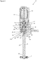
figure 3 illustre une coupe du dispositif d'agitation rotatif mettant notamment en évidence l'assemblage de la partie tubulaire avec l'arbre d'entraînement et le conduit d'acheminement de l'eau chaude et/ou de la vapeur ; - La
figure 4 met en évidence la présence d'un dispositif de détection de l'accouplement de la seconde extrémité de la partie tubulaire avec l'arbre d'entraînement ; - Les
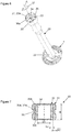
figures 5 et6 mettent en évidence le système de butées mécaniques anti-glissement sur le second dispositif d'accouplement ; - La
figure 7 illustre une réalisation préférentielle de l'organe métallique mis en oeuvre au niveau de la seconde extrémité de la partie tubulaire ; - La
figure 8 met en évidence la présence de capteur optique sur le dispositif d'agitation rotatif. - Dans la suite de la description, la machine de préparation de boissons est dénommée « machine ».
- Dans la suite de la description, les termes « horizontal », « vertical », « inférieur », « supérieur », « longitudinal », « transversal », « haut », « bas », qui pourraient être employés, le seront en considération de la position de la machine reposant sur un plan de travail, en situation d'usage.
- Sur les
figures 1 et 2 , la machine 1 comporte notamment un bâti 2, un support 3 sur lequel un récipient 4 peut être disposé durant la préparation d'une boisson, et un dispositif de distribution qui comporte notamment une buse 5 permettant la distribution d'une boisson à base de café, de thé et/ou de chocolat, par exemple. Ces caractéristiques sont déjà connues sur les machines de préparation de boissons, elles ne sont donc pas détaillées, l'homme du métier pouvant se référer aux machines existantes. - La machine 1 comprend également un dispositif d'agitation rotatif 6 comprenant un outil rotatif 7 autour d'un axe A et destiné à agiter une préparation contenue dans le récipient 4, par exemple du lait. Cet axe A est défini verticalement sur la machine 1. Le dispositif d'agitation rotatif 6 est monté en translation selon l'axe A, à l'intérieur d'une pièce de guidage 8 agencée sur le bâti 2, de sorte à permettre son déplacement selon une position haute illustrée en
figure 1 , où l'outil rotatif 7 est dégagé du récipient 4, et une position basse illustrée enfigure 2 , où l'outil rotatif 7 est inséré dans le récipient 4. - Tel qu'illustré sur la
figure 3 , le dispositif d'agitation rotatif 6 comporte un corps 9 monté en translation selon l'axe A sur la pièce de guidage 8 illustrée enfigures 1 et 2 , au moyen de glissières (non illustrées). A l'intérieur du corps 9 sont agencés un moteur électrique 10 et une boîte à vapeur 11. Le moteur électrique 10 entraîne en rotation selon l'axe A un arbre d'entrainement 12, lequel est monté en liaison pivot d'axe A vis-à-vis de la boîte à vapeur 11 au moyen de deux paliers de roulement étanches 13, 14; l'étanchéité mise en oeuvre entre la boîte à vapeur 11, les paliers 13, 14 et l'arbre d'entraînement 12 permettant de définir une chambre 15. Un canal radial (non illustré) traverse la boîte vapeur 11 et débouche dans la chambre 15, ce canal radial étant raccordé à un conduit souple (non illustré) qui permet les déplacements en translation selon l'axe A du dispositif d'agitation rotatif 6 vis-à-vis de la pièce de guidage 8, sans contrainte. Le conduit souple alimente en eau chaude et/ou en vapeur la chambre 15. L'arbre d'entrainement 12 présente une partie creuse 18 s'étendant selon l'axe A et débouchant d'un côté dans la chambre 15 grâce à un orifice 16 traversant ladite partie creuse 18 et, de l'autre côté, sur l'extrémité inférieure 19 de l'arbre d'entraînement 12. - Tel qu'illustré sur la
figure 3 , le dispositif d'agitation rotatif 6 comprend une partie tubulaire 20 qui s'étend selon l'axe A et passe au travers d'un fond 21 (illustré enfigures 1 et 2 ) de la pièce de guidage 8. L'extrémité inférieure 22 de la partie tubulaire 20 est assemblée avec l'outil rotatif 7, de préférence par emboîtement ou au moyen d'un assemblage à baïonnette. L'extrémité supérieure 23 de la partie tubulaire 20 est accouplée de manière amovible avec l'arbre d'entrainement 12. Ainsi, le canal souple, le conduit radial, la chambre 15, la partie creuse 18 de l'arbre d'entraînement 12 et la partie tubulaire 20 définissent un conduit 24 d'acheminement d'eau chaude et/ou de vapeur vers l'outil rotatif 7. - Tel qu'illustré en regard des
figures 3 à 7 , l'accouplement de l'extrémité supérieure 23 de la partie tubulaire 20 avec l'arbre d'entraînement 12 est mis en oeuvre par l'intermédiaire d'un dispositif d'accouplement magnétique 25. Ce dispositif d'accouplement magnétique 25 met en oeuvre une force d'attraction magnétique dans le sens de l'axe A, entre une paroi motrice 26 de l'arbre d'entraînement 12 et une paroi réceptrice 27 de l'extrémité supérieure 23 de la partie tubulaire 20, ces parois motrice 26 et réceptrice 27 s'étendant dans des plans perpendiculaires à l'axe A. Cette force d'attraction magnétique permet de plaquer la paroi réceptrice 27 contre la paroi motrice 26 en sorte de maintenir assemblée l'extrémité supérieure 23 de la partie tubulaire 20 avec l'arbre d'entraînement 12 et d'engendrer la rotation de la paroi réceptrice 27 sous l'action de la rotation de la paroi motrice 26. - Le dispositif d'accouplement magnétique 25 comprend une pièce de support 28 qui comporte la paroi motrice 26 sur sa face inférieure 28a, cette pièce de support 28 étant emboîtée en force sur l'arbre d'entraînement 12 de sorte que ladite pièce de support 28 et ledit arbre d'entraînement 12 sont assujettis et forment un ensemble. Le dispositif d'accouplement magnétique 25 comprend un aimant permanent 29 qui présente une forme tubulaire, comme l'illustre la
figure 3 , cet aimant permanent 29 étant logé à l'intérieur de la pièce de support 28 préalablement à son emboîtement en force sur l'arbre d'entraînement 12 qui passe au travers dudit aimant permanent 29. Des moyens de blocage en rotation (non illustrés) sont prévus entre la pièce de support 28 et l'aimant permanent 29 de façon à éviter la rotation de l'aimant permanent 29 selon l'axe A, à l'intérieur de la pièce de support 28. A titre d'exemple, on peut prévoir un emboîtement en force de l'aimant permanent 29 dans la pièce de support. - Le dispositif d'accouplement 25 comprend un organe métallique constitué d'un insert 30 qui présente une forme tubulaire, comme l'illustrent les
figures 3 et7 . L'extrémité supérieure 23 de la partie tubulaire 20, qui comporte la paroi réceptrice 27 sur sa face supérieure 23a, est surmoulée sur les parois extérieures 30a, 30b, 30c de l'insert 30, ce qui permet d'assujettir cet insert 30 sur ladite extrémité supérieure 23. Tel qu'illustré enfigure 7 , l'insert 30 comprend une bague externe 31 et une bague interne 32 qui sont montées en force l'une dans l'autre pour former une seule et même pièce (l'insert 30). La bague externe 31 est réalisée dans un matériau ferromagnétique et la bague interne 32 est réalisée dans un acier inoxydable résistant à la corrosion en ambiance vapeur. Cette bague interne 32 est montée glissante sur l'arbre d'entraînement 12. De préférence, la bague externe 31 est réalisée dans un inox 420 ou 430 ferromagnétique et la bague interne 32 est réalisée dans un inox 304. Grâce au surmoulage de l'extrémité supérieure 23 de la partie tubulaire 20 sur l'insert 30, la bague externe 31 est complétement revêtue par la matière - un polymère - de ladite extrémité supérieure 23, ce qui protège ladite bague externe 31 contre la corrosion. - En regard des
figures 3 et5 , un joint d'étanchéité 33 est logé dans une gorge 53 agencée sur l'arbre d'entraînement 12 et vient au contact de la paroi interne 34 de la bague interne 32 lorsque la paroi réceptrice 27 est plaquée contre la paroi motrice 26. Durant l'utilisation du dispositif d'agitation rotatif 6, l'injection d'eau chaude et/ou de vapeur peut engendrer une montée en pression dans le conduit 24 d'acheminement ; l'étanchéité mise en oeuvre grâce au joint d'étanchéité 33 évite tout risque de fuite d'eau chaude et/ou de vapeur au niveau du raccordement entre la partie tubulaire 20 et l'arbre d'entrainement 12. - Tel qu'illustré sur la
figure 3 , la paroi interne 34 de la bague interne 32 vient en contact avec la paroi externe 54 de la partie creuse 18 de l'arbre d'entraînement 12. Cette paroi externe 54 présente un diamètre externe D qui est très légèrement inférieur au diamètre interne D1 de la paroi interne 34 - de quelques microns - de sorte à réaliser un montage coulissant de la bague interne 32 sur ladite partie creuse 18. La bague interne 32 présente une hauteur H qui est supérieure au diamètre externe D pour assurer une maîtrise convenable de la rotation de la partie tubulaire 20 avec l'outil rotatif 7 et un guidage convenable de l'extrémité supérieure 23 de la partie tubulaire lors de son accouplement avec l'arbre d'entraînement 12. De préférence, la hauteur H est au moins cinq fois supérieure au diamètre externe D. - De préférence la bague externe 31 a une épaisseur E1 supérieure à 0,5mm, de préférence supérieure à 1mm afin de disposer d'une surface magnétisante suffisante pour réaliser l'attraction magnétique par l'aimant permanent 29. De même, la bague interne 32 a une épaisseur E2 supérieure à 0,5mm, de préférence supérieure à 1mm en sorte d'éviter une déformation de la bague interne 32 lors de son emboîtement en force dans la bague externe 31. Une gorge 55 est mise en oeuvre sur le contour externe 31a de la bague externe 31 afin d'améliorer l'ancrage de l'insert 30 dans l'extrémité supérieure 23 de la partie tubulaire 20 lors du surmoulage.
- En regard des
figures 5 et6 , la paroi motrice 26 comprend quatre organes proéminents 35 sous la forme de rampes hélicoïdales uniformément réparties autour d'un cercle de centre passant par l'axe A. La paroi réceptrice 27 comprend, quant à elle, quatre logements 36 ayant une forme complémentaire à celle des quatre organes proéminents 35. Le nombre d'organes proéminents 35 et de logements 36 pourrait être différent, par exemple de trois. Lors de l'emboîtement de l'extrémité supérieure 23 de la partie tubulaire 20 sur l'arbre d'entraînement 12, l'aimant permanent 29 exerce une force d'attraction magnétique sur l'insert 30, ce qui attire la paroi réceptrice 27 vers la paroi motrice 26, les organes proéminents 35 se logeant au moins partiellement respectivement dans les logements 36 ; la forme hélicoïdale des organes proéminents 35 et des logements 36 et la force d'attraction magnétique assurent alors un auto positionnement desdits organes proéminents 35 dans lesdits logements 36 jusqu'à ce que la paroi réceptrice 27 vienne totalement en butée contre la paroi motrice 26 où lesdits éléments sont auto-alignés. Durant la rotation de l'arbre d'entraînement 12, qui s'effectue dans le sens de la flèche 37, les extrémités 35a des organes proéminents 35 viennent en butée contre les extrémités 36a des logements 36, ce qui assure un entraînement positif de la partie tubulaire 20. Ainsi, les organes proéminents 35 et les logements 36 mettent en oeuvre un système de butées mécaniques anti-glissement qui assure un alignement automatique entre la paroi motrice 26 et la paroi réceptrice 27. - En regard des
figures 4 à 6 et8 , le dispositif d'agitation rotatif 6 comprend un dispositif de détection 38 qui permet de détecter l'accouplement de l'extrémité supérieure 23 de la partie tubulaire 20 avec l'arbre d'entraînement 12 grâce audit dispositif d'accouplement magnétique 25. Le dispositif de détection 38 comprend une cellule 39 émettrice d'un faisceau lumineux, de préférence un émetteur optique infrarouge qui présente l'avantage d'être peu sensible à la lumière extérieure. Le dispositif de détection 38 comprend également une cellule 40 réceptrice dudit faisceau lumineux, de préférence un capteur optique infrarouge qui présente également l'avantage d'être peu sensible à la lumière extérieure. Le dispositif de détection 38 comporte deux guides optiques 41, 42 de renvoi à 90° du faisceau lumineux, ce qui permet de loger les cellules émettrice 39 et réceptrice 40 verticalement à l'intérieur du corps 9 du dispositif d'agitation rotatif 6 et d'effectuer un renvoi d'angle du faisceau lumineux sous le corps 9, selon une trajectoire horizontale passant dans la zone d'accouplement 56 entre l'extrémité supérieure 23 de la partie tubulaire 20 et l'arbre d'entraînement 12. Un capot 43 se positionne sous le corps 9 pour assurer une protection des guides optiques 41, 42 et éviter les perturbations de la lumière extérieure. L'extrémité supérieure 23 de la partie tubulaire 20, dans laquelle est logé l'insert 30, comporte une excroissance en diamètre qui permet de couper le faisceau lumineux lors de l'accouplement de ladite extrémité supérieure 23 avec l'arbre d'entrainement 12. Cette coupure du faisceau lumineux signale donc la présence de la partie tubulaire 20 avec l'outil rotatif 7 sur le dispositif d'agitation rotatif 6. - La mise en place de la partie tubulaire 20, assemblée avec l'outil rotatif 7, sur l'arbre d'entrainement 12 s'effectue simplement par emboîtement, comme expliqué précédemment. Leur retrait s'effectue également simplement en tirant dessus pour les dégager ; il suffit d'exercer une force de traction supérieure à la force d'attraction magnétique de l'aimant permanent 29.
- La description qui précède d'un mode préférentiel de réalisation n'est pas limitative, des variantes pouvant être envisagées sans sortir du cadre de l'invention.
- A titre d'exemple, la machine 1 pourrait comprendre simplement le dispositif d'agitation rotatif 6, la préparation de café, de thé et/ou de chocolat pouvant être réalisée sur une machine de préparation de boissons indépendante disposant uniquement d'un dispositif de distribution de boissons.
Claims (14)
- Dispositif d'agitation rotatif (6) d'une machine de préparation de boissons (1), ledit dispositif comprenant un outil rotatif (7) autour d'un axe A et destiné à agiter une préparation contenue dans un récipient (4) et un conduit (24) d'acheminement d'eau chaude et/ou de vapeur vers l'outil rotatif, ledit conduit d'acheminement comportant une partie creuse (18) d'un arbre d'entrainement (12) qui communique avec une partie tubulaire (20) qui s'étend le long de l'axe A entre une première extrémité (22) qui est accouplée à l'outil rotatif au moyen d'un premier dispositif d'accouplement et une seconde extrémité (23) qui est accouplée à ladite partie creuse au moyen d'un second dispositif d'accouplement caractérisé en ce que le second dispositif d'accouplement est un dispositif d'accouplement magnétique (25) configuré pour générer une force d'attraction magnétique le long de l'axe A entre l'arbre d'entrainement (12) et la seconde extrémité (23) de la partie tubulaire (20), le dispositif d'accouplement magnétique comportant un organe métallique (30) agencé sur ladite seconde extrémité (23) et formé par une bague interne (32) réalisée en acier inoxydable résistant à la corrosion en ambiance vapeur et une bague externe (31) réalisée en un matériau ferromagnétique, la bague interne (32) étant destinée à coulisser sur la partie creuse (18) qui est réalisée en acier inoxydable résistant à la corrosion en ambiance vapeur, lors de la réalisation de l'accouplement.
- Dispositif d'agitation rotatif (6) selon la revendication 1, caractérisé en ce que la bague interne (32) est montée serrante dans la bague externe (31).
- Dispositif d'agitation rotatif (6) selon l'une quelconque des revendications 1 à 2, caractérisé en ce que la seconde extrémité (23) de la partie tubulaire (20) est réalisée en une matière plastique qui entoure une face extérieure de la bague externe (31).
- Dispositif d'agitation rotatif (6) selon l'une quelconque des revendications 1 à 3, caractérisé en ce que la partie creuse (18) de l'arbre d'entrainement (12) présente un diamètre externe D et en ce que la bague interne (32) présente une hauteur H, la hauteur H étant supérieure au diamètre D.
- Dispositif d'agitation rotatif (6) selon l'une quelconque des revendications 1 à 4, caractérisé en ce que la partie creuse (18) de l'arbre d'entrainement (12) comporte une gorge (53) munie d'un joint d'étanchéité (33) qui est agencé en vis-à-vis de la bague interne (32) lorsque la partie tubulaire (20) est accouplée à l'arbre d'entrainement (12).
- Dispositif d'agitation rotatif (6) selon l'une quelconque des revendications 1 à 5, caractérisé en ce que l'arbre d'entrainement (12) comporte un élément magnétique formé par un aimant permanent (29) qui génère sur l'organe métallique (30) une force d'attraction magnétique et qui tend à plaquer une paroi motrice (26) de l'arbre d'entrainement contre une paroi réceptrice (27) de la seconde extrémité (23) de la partie tubulaire (20) pour transmettre le mouvement de rotation de l'arbre d'entrainement (12) à la partie tubulaire (20).
- Dispositif d'agitation rotatif (6) selon la revendication 6, caractérisé en ce que la paroi motrice (26) de l'arbre d'entrainement (12) et la paroi réceptrice (27) agencée sur la seconde extrémité (23) de la partie tubulaire (20) s'étendent dans un plan perpendiculaire à l'axe A.
- Dispositif d'agitation rotatif (6) selon l'une quelconque des revendications 1 à 7, caractérisé en ce qu'il comporte un dispositif de détection (38) optique de la présence de la partie tubulaire (20) sur l'arbre d'entrainement (12) comportant une cellule émettrice (39) d'un faisceau lumineux et une cellule réceptrice (40) dudit faisceau, la partie tubulaire comportant une excroissance en diamètre au niveau de l'organe métallique (30) qui coupe le faisceau lorsque ladite partie tubulaire est assemblée sur l'arbre d'entrainement.
- Dispositif d'agitation rotatif (6) selon la revendication 8, caractérisé en ce que le dispositif de détection (38) optique comporte au moins un guide optique (41, 42) de renvoi à 90° du faisceau lumineux.
- Dispositif d'agitation rotatif (6) selon l'une quelconque des revendications 1 à 9, caractérisé en ce que le second dispositif d'accouplement comporte un système de butées mécaniques anti-glissement qui s'alignent automatiquement lors de l'accouplement sous l'effet de la force d'attraction magnétique.
- Dispositif d'agitation rotatif (6) selon l'une quelconque des revendications 1 à 10, caractérisé en ce qu'il comporte un moteur électrique (10) destiné à entrainer l'arbre d'entraînement (12).
- Dispositif d'agitation rotatif (6) selon l'une quelconque des revendications 1 à 11, caractérisé en ce que ledit dispositif d'agitation comprend une boite à vapeur (11) comportant une chambre (15), un canal radial d'entrée vapeur, deux paliers étanches (13, 14) de guidage de l'arbre d'entrainement (12), la partie creuse (18) de l'arbre d'entraînement (12) reliant la chambre (15) à la partie tubulaire (20) de façon à acheminer l'eau chaude et/ou la vapeur.
- Dispositif d'agitation rotatif (6) selon l'une quelconque des revendications 1 à 12, caractérisé en ce que la bague externe (31) a une épaisseur E1 supérieure à 0,5mm, de préférence supérieure à 1mm.
- Dispositif d'agitation rotatif (6) selon l'une quelconque des revendications 1 à 13, caractérisé en ce que la bague interne (32) a une épaisseur E2 supérieure à 0,5mm, de préférence supérieure à 1mm.
Applications Claiming Priority (1)
| Application Number | Priority Date | Filing Date | Title |
|---|---|---|---|
| FR1858668A FR3086151B1 (fr) | 2018-09-24 | 2018-09-24 | Dispositif d'agitation rotatif de machine de preparation de boissons equipe d'un dispositif d'accouplement magnetique |
Publications (2)
| Publication Number | Publication Date |
|---|---|
| EP3626137A1 true EP3626137A1 (fr) | 2020-03-25 |
| EP3626137B1 EP3626137B1 (fr) | 2021-06-02 |
Family
ID=65243812
Family Applications (1)
| Application Number | Title | Priority Date | Filing Date |
|---|---|---|---|
| EP19196988.0A Active EP3626137B1 (fr) | 2018-09-24 | 2019-09-12 | Dispositif d'agitation rotatif de machine de préparation de boissons équipé d'un dispositif d'accouplement magnétique |
Country Status (2)
| Country | Link |
|---|---|
| EP (1) | EP3626137B1 (fr) |
| FR (1) | FR3086151B1 (fr) |
Families Citing this family (1)
| Publication number | Priority date | Publication date | Assignee | Title |
|---|---|---|---|---|
| US11812892B1 (en) | 2022-04-25 | 2023-11-14 | Sharkninja Operating Llc | Fluid texturing device |
Citations (3)
| Publication number | Priority date | Publication date | Assignee | Title |
|---|---|---|---|---|
| US20130000490A1 (en) * | 2010-03-17 | 2013-01-03 | De'longhi Appliances S.R.L. | Device Associable To a Steam Dispenser For Production Of An Aromatic Beverage And A Coffee Machine Exhibiting The Device |
| EP2721980A1 (fr) | 2012-10-22 | 2014-04-23 | Imper S.p.A. | Dispositif pour la préparation d'une boisson émulsifiée |
| FR3056896A1 (fr) * | 2016-09-30 | 2018-04-06 | Seb S.A. | Dispositif de preparation de boissons muni d'une buse vapeur mobile |
-
2018
- 2018-09-24 FR FR1858668A patent/FR3086151B1/fr not_active Expired - Fee Related
-
2019
- 2019-09-12 EP EP19196988.0A patent/EP3626137B1/fr active Active
Patent Citations (3)
| Publication number | Priority date | Publication date | Assignee | Title |
|---|---|---|---|---|
| US20130000490A1 (en) * | 2010-03-17 | 2013-01-03 | De'longhi Appliances S.R.L. | Device Associable To a Steam Dispenser For Production Of An Aromatic Beverage And A Coffee Machine Exhibiting The Device |
| EP2721980A1 (fr) | 2012-10-22 | 2014-04-23 | Imper S.p.A. | Dispositif pour la préparation d'une boisson émulsifiée |
| FR3056896A1 (fr) * | 2016-09-30 | 2018-04-06 | Seb S.A. | Dispositif de preparation de boissons muni d'une buse vapeur mobile |
Also Published As
| Publication number | Publication date |
|---|---|
| FR3086151A1 (fr) | 2020-03-27 |
| EP3626137B1 (fr) | 2021-06-02 |
| FR3086151B1 (fr) | 2020-09-18 |
Similar Documents
| Publication | Publication Date | Title |
|---|---|---|
| EP3626138B1 (fr) | Dispositif d'agitation rotatif de machine de préparation de boissons équipe d'un dispositif d'accouplement magnétique | |
| EP2005869B1 (fr) | Appareil de préparation culinaire muni d'un dispositif de sécurité | |
| CA2644306C (fr) | Vanne de decharge dans une turbomachine | |
| EP3586703B1 (fr) | Dispositif d'agitation rotatif de machine de préparation de boissons équipé d'un clapet anti-retour | |
| FR2474640A1 (fr) | Raccord rapide anti-fuite, notamment pour tuyauteries de transport de fluides hydrauliques | |
| FR2552521A1 (fr) | Detendeur pour raccord rapide | |
| FR2973720A1 (fr) | Dispositif de connexion d'une carte microfluidique | |
| EP4306837B1 (fr) | Élément de raccord pour un raccordement fluidique à un terminal | |
| EP3626137B1 (fr) | Dispositif d'agitation rotatif de machine de préparation de boissons équipé d'un dispositif d'accouplement magnétique | |
| EP3626136B1 (fr) | Machine de préparation de boissons avec dispositif d'agitation rotatif et clapet de mise à l'air d'un conduit d'acheminement d'eau chaude et/ou de vapeur | |
| FR2898206A1 (fr) | Dispositif d'assemblage de deux elements de structure | |
| EP3586702B1 (fr) | Dispositif d'agitation rotatif de machine de préparation de boissons équipe d'un manchon d'accouplement | |
| FR2824382A1 (fr) | Dispositif de connexion de parties d'un conduit aeraulique d'aspiration d'un appareil recuperateur de dechets | |
| EP3102865B1 (fr) | Bague d'accrochage d'une canalisation à un corps tubulaire et moyens de connexion comportant une telle bague | |
| WO2002028248A1 (fr) | Recipient de travail pour robot menager, comportant un axe d'entrainement rotatif etanche | |
| FR2974612A1 (fr) | Dispositif de fixation et de raccordement d'un organe d'alimentation d'appareil sanitaire sur une paroi et son procede de montage | |
| CA2689309C (fr) | Ensemble pour machine de preparation de boissons comprenant une chaudiere | |
| WO2012174671A1 (fr) | Ustensile manuel, notamment article de vaisselle | |
| EP3450617B1 (fr) | Appareil de repassage comportant une base reliée par un cordon à un fer à repasser | |
| FR3015298A1 (fr) | Ensemble hydraulique de generateur de jets pulses ou non pulses moyenne et haute pression | |
| FR3092771A1 (fr) | Meuble pour l’agitation du contenu de pots mélangeurs | |
| FR3135759A1 (fr) | Filtre à air moteur pourvu d’un dispositif à capteur et méthode de connexion du dispositif à capteur en sortie du filtre | |
| FR2873393A1 (fr) | Dispositif de fixation et de connexion d'un compteur au niveau d'un poste de delivrance d'un fluide | |
| CH685988A5 (fr) | Doseur volumetrique de produits, notamment pulverulents. | |
| EP3105560A1 (fr) | Dispositif de fixation d'un capteur sur une piece |
Legal Events
| Date | Code | Title | Description |
|---|---|---|---|
| PUAI | Public reference made under article 153(3) epc to a published international application that has entered the european phase |
Free format text: ORIGINAL CODE: 0009012 |
|
| STAA | Information on the status of an ep patent application or granted ep patent |
Free format text: STATUS: THE APPLICATION HAS BEEN PUBLISHED |
|
| AK | Designated contracting states |
Kind code of ref document: A1 Designated state(s): AL AT BE BG CH CY CZ DE DK EE ES FI FR GB GR HR HU IE IS IT LI LT LU LV MC MK MT NL NO PL PT RO RS SE SI SK SM TR |
|
| AX | Request for extension of the european patent |
Extension state: BA ME |
|
| STAA | Information on the status of an ep patent application or granted ep patent |
Free format text: STATUS: REQUEST FOR EXAMINATION WAS MADE |
|
| 17P | Request for examination filed |
Effective date: 20200917 |
|
| RBV | Designated contracting states (corrected) |
Designated state(s): AL AT BE BG CH CY CZ DE DK EE ES FI FR GB GR HR HU IE IS IT LI LT LU LV MC MK MT NL NO PL PT RO RS SE SI SK SM TR |
|
| GRAP | Despatch of communication of intention to grant a patent |
Free format text: ORIGINAL CODE: EPIDOSNIGR1 |
|
| STAA | Information on the status of an ep patent application or granted ep patent |
Free format text: STATUS: GRANT OF PATENT IS INTENDED |
|
| INTG | Intention to grant announced |
Effective date: 20210324 |
|
| GRAS | Grant fee paid |
Free format text: ORIGINAL CODE: EPIDOSNIGR3 |
|
| GRAA | (expected) grant |
Free format text: ORIGINAL CODE: 0009210 |
|
| STAA | Information on the status of an ep patent application or granted ep patent |
Free format text: STATUS: THE PATENT HAS BEEN GRANTED |
|
| REG | Reference to a national code |
Ref country code: CH Ref legal event code: EP |
|
| AK | Designated contracting states |
Kind code of ref document: B1 Designated state(s): AL AT BE BG CH CY CZ DE DK EE ES FI FR GB GR HR HU IE IS IT LI LT LU LV MC MK MT NL NO PL PT RO RS SE SI SK SM TR |
|
| REG | Reference to a national code |
Ref country code: GB Ref legal event code: FG4D Free format text: NOT ENGLISH |
|
| REG | Reference to a national code |
Ref country code: AT Ref legal event code: REF Ref document number: 1397651 Country of ref document: AT Kind code of ref document: T Effective date: 20210615 |
|
| REG | Reference to a national code |
Ref country code: IE Ref legal event code: FG4D Free format text: LANGUAGE OF EP DOCUMENT: FRENCH |
|
| REG | Reference to a national code |
Ref country code: DE Ref legal event code: R096 Ref document number: 602019005039 Country of ref document: DE |
|
| REG | Reference to a national code |
Ref country code: NL Ref legal event code: FP |
|
| REG | Reference to a national code |
Ref country code: LT Ref legal event code: MG9D |
|
| PG25 | Lapsed in a contracting state [announced via postgrant information from national office to epo] |
Ref country code: HR Free format text: LAPSE BECAUSE OF FAILURE TO SUBMIT A TRANSLATION OF THE DESCRIPTION OR TO PAY THE FEE WITHIN THE PRESCRIBED TIME-LIMIT Effective date: 20210602 Ref country code: LT Free format text: LAPSE BECAUSE OF FAILURE TO SUBMIT A TRANSLATION OF THE DESCRIPTION OR TO PAY THE FEE WITHIN THE PRESCRIBED TIME-LIMIT Effective date: 20210602 Ref country code: FI Free format text: LAPSE BECAUSE OF FAILURE TO SUBMIT A TRANSLATION OF THE DESCRIPTION OR TO PAY THE FEE WITHIN THE PRESCRIBED TIME-LIMIT Effective date: 20210602 Ref country code: BG Free format text: LAPSE BECAUSE OF FAILURE TO SUBMIT A TRANSLATION OF THE DESCRIPTION OR TO PAY THE FEE WITHIN THE PRESCRIBED TIME-LIMIT Effective date: 20210902 |
|
| PG25 | Lapsed in a contracting state [announced via postgrant information from national office to epo] |
Ref country code: PL Free format text: LAPSE BECAUSE OF FAILURE TO SUBMIT A TRANSLATION OF THE DESCRIPTION OR TO PAY THE FEE WITHIN THE PRESCRIBED TIME-LIMIT Effective date: 20210602 Ref country code: NO Free format text: LAPSE BECAUSE OF FAILURE TO SUBMIT A TRANSLATION OF THE DESCRIPTION OR TO PAY THE FEE WITHIN THE PRESCRIBED TIME-LIMIT Effective date: 20210902 Ref country code: LV Free format text: LAPSE BECAUSE OF FAILURE TO SUBMIT A TRANSLATION OF THE DESCRIPTION OR TO PAY THE FEE WITHIN THE PRESCRIBED TIME-LIMIT Effective date: 20210602 Ref country code: SE Free format text: LAPSE BECAUSE OF FAILURE TO SUBMIT A TRANSLATION OF THE DESCRIPTION OR TO PAY THE FEE WITHIN THE PRESCRIBED TIME-LIMIT Effective date: 20210602 Ref country code: RS Free format text: LAPSE BECAUSE OF FAILURE TO SUBMIT A TRANSLATION OF THE DESCRIPTION OR TO PAY THE FEE WITHIN THE PRESCRIBED TIME-LIMIT Effective date: 20210602 Ref country code: GR Free format text: LAPSE BECAUSE OF FAILURE TO SUBMIT A TRANSLATION OF THE DESCRIPTION OR TO PAY THE FEE WITHIN THE PRESCRIBED TIME-LIMIT Effective date: 20210903 |
|
| PG25 | Lapsed in a contracting state [announced via postgrant information from national office to epo] |
Ref country code: SM Free format text: LAPSE BECAUSE OF FAILURE TO SUBMIT A TRANSLATION OF THE DESCRIPTION OR TO PAY THE FEE WITHIN THE PRESCRIBED TIME-LIMIT Effective date: 20210602 Ref country code: PT Free format text: LAPSE BECAUSE OF FAILURE TO SUBMIT A TRANSLATION OF THE DESCRIPTION OR TO PAY THE FEE WITHIN THE PRESCRIBED TIME-LIMIT Effective date: 20211004 Ref country code: RO Free format text: LAPSE BECAUSE OF FAILURE TO SUBMIT A TRANSLATION OF THE DESCRIPTION OR TO PAY THE FEE WITHIN THE PRESCRIBED TIME-LIMIT Effective date: 20210602 Ref country code: CZ Free format text: LAPSE BECAUSE OF FAILURE TO SUBMIT A TRANSLATION OF THE DESCRIPTION OR TO PAY THE FEE WITHIN THE PRESCRIBED TIME-LIMIT Effective date: 20210602 Ref country code: SK Free format text: LAPSE BECAUSE OF FAILURE TO SUBMIT A TRANSLATION OF THE DESCRIPTION OR TO PAY THE FEE WITHIN THE PRESCRIBED TIME-LIMIT Effective date: 20210602 Ref country code: ES Free format text: LAPSE BECAUSE OF FAILURE TO SUBMIT A TRANSLATION OF THE DESCRIPTION OR TO PAY THE FEE WITHIN THE PRESCRIBED TIME-LIMIT Effective date: 20210602 Ref country code: EE Free format text: LAPSE BECAUSE OF FAILURE TO SUBMIT A TRANSLATION OF THE DESCRIPTION OR TO PAY THE FEE WITHIN THE PRESCRIBED TIME-LIMIT Effective date: 20210602 |
|
| REG | Reference to a national code |
Ref country code: DE Ref legal event code: R097 Ref document number: 602019005039 Country of ref document: DE |
|
| PLBE | No opposition filed within time limit |
Free format text: ORIGINAL CODE: 0009261 |
|
| STAA | Information on the status of an ep patent application or granted ep patent |
Free format text: STATUS: NO OPPOSITION FILED WITHIN TIME LIMIT |
|
| PG25 | Lapsed in a contracting state [announced via postgrant information from national office to epo] |
Ref country code: DK Free format text: LAPSE BECAUSE OF FAILURE TO SUBMIT A TRANSLATION OF THE DESCRIPTION OR TO PAY THE FEE WITHIN THE PRESCRIBED TIME-LIMIT Effective date: 20210602 |
|
| 26N | No opposition filed |
Effective date: 20220303 |
|
| REG | Reference to a national code |
Ref country code: BE Ref legal event code: MM Effective date: 20210930 |
|
| PG25 | Lapsed in a contracting state [announced via postgrant information from national office to epo] |
Ref country code: MC Free format text: LAPSE BECAUSE OF FAILURE TO SUBMIT A TRANSLATION OF THE DESCRIPTION OR TO PAY THE FEE WITHIN THE PRESCRIBED TIME-LIMIT Effective date: 20210602 Ref country code: AL Free format text: LAPSE BECAUSE OF FAILURE TO SUBMIT A TRANSLATION OF THE DESCRIPTION OR TO PAY THE FEE WITHIN THE PRESCRIBED TIME-LIMIT Effective date: 20210602 |
|
| PG25 | Lapsed in a contracting state [announced via postgrant information from national office to epo] |
Ref country code: LU Free format text: LAPSE BECAUSE OF NON-PAYMENT OF DUE FEES Effective date: 20210912 Ref country code: IE Free format text: LAPSE BECAUSE OF NON-PAYMENT OF DUE FEES Effective date: 20210912 Ref country code: BE Free format text: LAPSE BECAUSE OF NON-PAYMENT OF DUE FEES Effective date: 20210930 |
|
| REG | Reference to a national code |
Ref country code: AT Ref legal event code: UEP Ref document number: 1397651 Country of ref document: AT Kind code of ref document: T Effective date: 20210602 |
|
| PG25 | Lapsed in a contracting state [announced via postgrant information from national office to epo] |
Ref country code: CY Free format text: LAPSE BECAUSE OF FAILURE TO SUBMIT A TRANSLATION OF THE DESCRIPTION OR TO PAY THE FEE WITHIN THE PRESCRIBED TIME-LIMIT Effective date: 20210602 |
|
| PG25 | Lapsed in a contracting state [announced via postgrant information from national office to epo] |
Ref country code: HU Free format text: LAPSE BECAUSE OF FAILURE TO SUBMIT A TRANSLATION OF THE DESCRIPTION OR TO PAY THE FEE WITHIN THE PRESCRIBED TIME-LIMIT; INVALID AB INITIO Effective date: 20190912 |
|
| PG25 | Lapsed in a contracting state [announced via postgrant information from national office to epo] |
Ref country code: MK Free format text: LAPSE BECAUSE OF FAILURE TO SUBMIT A TRANSLATION OF THE DESCRIPTION OR TO PAY THE FEE WITHIN THE PRESCRIBED TIME-LIMIT Effective date: 20210602 |
|
| PG25 | Lapsed in a contracting state [announced via postgrant information from national office to epo] |
Ref country code: TR Free format text: LAPSE BECAUSE OF FAILURE TO SUBMIT A TRANSLATION OF THE DESCRIPTION OR TO PAY THE FEE WITHIN THE PRESCRIBED TIME-LIMIT Effective date: 20210602 |
|
| PG25 | Lapsed in a contracting state [announced via postgrant information from national office to epo] |
Ref country code: MT Free format text: LAPSE BECAUSE OF FAILURE TO SUBMIT A TRANSLATION OF THE DESCRIPTION OR TO PAY THE FEE WITHIN THE PRESCRIBED TIME-LIMIT Effective date: 20210602 |
|
| REG | Reference to a national code |
Ref country code: CH Ref legal event code: U11 Free format text: ST27 STATUS EVENT CODE: U-0-0-U10-U11 (AS PROVIDED BY THE NATIONAL OFFICE) Effective date: 20251001 |
|
| PGFP | Annual fee paid to national office [announced via postgrant information from national office to epo] |
Ref country code: DE Payment date: 20250916 Year of fee payment: 7 |
|
| PGFP | Annual fee paid to national office [announced via postgrant information from national office to epo] |
Ref country code: NL Payment date: 20250909 Year of fee payment: 7 Ref country code: IT Payment date: 20250909 Year of fee payment: 7 |
|
| PGFP | Annual fee paid to national office [announced via postgrant information from national office to epo] |
Ref country code: GB Payment date: 20250919 Year of fee payment: 7 |
|
| PGFP | Annual fee paid to national office [announced via postgrant information from national office to epo] |
Ref country code: FR Payment date: 20250929 Year of fee payment: 7 Ref country code: AT Payment date: 20250822 Year of fee payment: 7 |
|
| PGFP | Annual fee paid to national office [announced via postgrant information from national office to epo] |
Ref country code: CH Payment date: 20251001 Year of fee payment: 7 |