EP3626068B1 - Liquid dispenser for animals - Google Patents
Liquid dispenser for animals Download PDFInfo
- Publication number
- EP3626068B1 EP3626068B1 EP19198196.8A EP19198196A EP3626068B1 EP 3626068 B1 EP3626068 B1 EP 3626068B1 EP 19198196 A EP19198196 A EP 19198196A EP 3626068 B1 EP3626068 B1 EP 3626068B1
- Authority
- EP
- European Patent Office
- Prior art keywords
- wireless power
- docking station
- water
- docking
- tank
- Prior art date
- Legal status (The legal status is an assumption and is not a legal conclusion. Google has not performed a legal analysis and makes no representation as to the accuracy of the status listed.)
- Active
Links
Images




Classifications
-
- A—HUMAN NECESSITIES
- A01—AGRICULTURE; FORESTRY; ANIMAL HUSBANDRY; HUNTING; TRAPPING; FISHING
- A01K—ANIMAL HUSBANDRY; AVICULTURE; APICULTURE; PISCICULTURE; FISHING; REARING OR BREEDING ANIMALS, NOT OTHERWISE PROVIDED FOR; NEW BREEDS OF ANIMALS
- A01K7/00—Watering equipment for stock or game
- A01K7/02—Automatic devices
- A01K7/022—Pumps actuated by the drinking animal
-
- A—HUMAN NECESSITIES
- A01—AGRICULTURE; FORESTRY; ANIMAL HUSBANDRY; HUNTING; TRAPPING; FISHING
- A01K—ANIMAL HUSBANDRY; AVICULTURE; APICULTURE; PISCICULTURE; FISHING; REARING OR BREEDING ANIMALS, NOT OTHERWISE PROVIDED FOR; NEW BREEDS OF ANIMALS
- A01K39/00—Feeding or drinking appliances for poultry or other birds
- A01K39/02—Drinking appliances
-
- A—HUMAN NECESSITIES
- A01—AGRICULTURE; FORESTRY; ANIMAL HUSBANDRY; HUNTING; TRAPPING; FISHING
- A01K—ANIMAL HUSBANDRY; AVICULTURE; APICULTURE; PISCICULTURE; FISHING; REARING OR BREEDING ANIMALS, NOT OTHERWISE PROVIDED FOR; NEW BREEDS OF ANIMALS
- A01K7/00—Watering equipment for stock or game
- A01K7/02—Automatic devices
-
- A—HUMAN NECESSITIES
- A01—AGRICULTURE; FORESTRY; ANIMAL HUSBANDRY; HUNTING; TRAPPING; FISHING
- A01K—ANIMAL HUSBANDRY; AVICULTURE; APICULTURE; PISCICULTURE; FISHING; REARING OR BREEDING ANIMALS, NOT OTHERWISE PROVIDED FOR; NEW BREEDS OF ANIMALS
- A01K7/00—Watering equipment for stock or game
- A01K7/02—Automatic devices
- A01K7/025—Water tanks
-
- A—HUMAN NECESSITIES
- A01—AGRICULTURE; FORESTRY; ANIMAL HUSBANDRY; HUNTING; TRAPPING; FISHING
- A01K—ANIMAL HUSBANDRY; AVICULTURE; APICULTURE; PISCICULTURE; FISHING; REARING OR BREEDING ANIMALS, NOT OTHERWISE PROVIDED FOR; NEW BREEDS OF ANIMALS
- A01K7/00—Watering equipment for stock or game
- A01K7/02—Automatic devices
- A01K7/027—Drinking equipment with water heaters, coolers or means for preventing freezing
-
- B—PERFORMING OPERATIONS; TRANSPORTING
- B01—PHYSICAL OR CHEMICAL PROCESSES OR APPARATUS IN GENERAL
- B01D—SEPARATION
- B01D29/00—Filters with filtering elements stationary during filtration, e.g. pressure or suction filters, not covered by groups B01D24/00 - B01D27/00; Filtering elements therefor
- B01D29/50—Filters with filtering elements stationary during filtration, e.g. pressure or suction filters, not covered by groups B01D24/00 - B01D27/00; Filtering elements therefor with multiple filtering elements, characterised by their mutual disposition
- B01D29/56—Filters with filtering elements stationary during filtration, e.g. pressure or suction filters, not covered by groups B01D24/00 - B01D27/00; Filtering elements therefor with multiple filtering elements, characterised by their mutual disposition in series connection
-
- B—PERFORMING OPERATIONS; TRANSPORTING
- B67—OPENING, CLOSING OR CLEANING BOTTLES, JARS OR SIMILAR CONTAINERS; LIQUID HANDLING
- B67D—DISPENSING, DELIVERING OR TRANSFERRING LIQUIDS, NOT OTHERWISE PROVIDED FOR
- B67D3/00—Apparatus or devices for controlling flow of liquids under gravity from storage containers for dispensing purposes
- B67D3/0003—Apparatus or devices for controlling flow of liquids under gravity from storage containers for dispensing purposes provided with automatic fluid control means
-
- C—CHEMISTRY; METALLURGY
- C02—TREATMENT OF WATER, WASTE WATER, SEWAGE, OR SLUDGE
- C02F—TREATMENT OF WATER, WASTE WATER, SEWAGE, OR SLUDGE
- C02F1/00—Treatment of water, waste water, or sewage
- C02F1/001—Processes for the treatment of water whereby the filtration technique is of importance
-
- C—CHEMISTRY; METALLURGY
- C02—TREATMENT OF WATER, WASTE WATER, SEWAGE, OR SLUDGE
- C02F—TREATMENT OF WATER, WASTE WATER, SEWAGE, OR SLUDGE
- C02F1/00—Treatment of water, waste water, or sewage
- C02F1/001—Processes for the treatment of water whereby the filtration technique is of importance
- C02F1/003—Processes for the treatment of water whereby the filtration technique is of importance using household-type filters for producing potable water, e.g. pitchers, bottles, faucet mounted devices
-
- C—CHEMISTRY; METALLURGY
- C02—TREATMENT OF WATER, WASTE WATER, SEWAGE, OR SLUDGE
- C02F—TREATMENT OF WATER, WASTE WATER, SEWAGE, OR SLUDGE
- C02F1/00—Treatment of water, waste water, or sewage
- C02F1/30—Treatment of water, waste water, or sewage by irradiation
- C02F1/32—Treatment of water, waste water, or sewage by irradiation with ultraviolet light
-
- E—FIXED CONSTRUCTIONS
- E03—WATER SUPPLY; SEWERAGE
- E03B—INSTALLATIONS OR METHODS FOR OBTAINING, COLLECTING, OR DISTRIBUTING WATER
- E03B9/00—Methods or installations for drawing-off water
- E03B9/02—Hydrants; Arrangements of valves therein; Keys for hydrants
- E03B9/20—Pillar fountains or like apparatus for dispensing drinking water
-
- F—MECHANICAL ENGINEERING; LIGHTING; HEATING; WEAPONS; BLASTING
- F21—LIGHTING
- F21V—FUNCTIONAL FEATURES OR DETAILS OF LIGHTING DEVICES OR SYSTEMS THEREOF; STRUCTURAL COMBINATIONS OF LIGHTING DEVICES WITH OTHER ARTICLES, NOT OTHERWISE PROVIDED FOR
- F21V33/00—Structural combinations of lighting devices with other articles, not otherwise provided for
-
- H—ELECTRICITY
- H02—GENERATION; CONVERSION OR DISTRIBUTION OF ELECTRIC POWER
- H02J—ELECTRIC POWER NETWORKS; CIRCUIT ARRANGEMENTS OR SYSTEMS FOR SUPPLYING OR DISTRIBUTING ELECTRIC POWER; SYSTEMS FOR STORING ELECTRIC ENERGY
- H02J50/00—Circuit arrangements or systems for wireless supply or distribution of electric power
- H02J50/005—Mechanical details of housing or structure aiming to accommodate the power transfer means, e.g. mechanical integration of coils, antennas or transducers into emitting or receiving devices
-
- H—ELECTRICITY
- H02—GENERATION; CONVERSION OR DISTRIBUTION OF ELECTRIC POWER
- H02J—ELECTRIC POWER NETWORKS; CIRCUIT ARRANGEMENTS OR SYSTEMS FOR SUPPLYING OR DISTRIBUTING ELECTRIC POWER; SYSTEMS FOR STORING ELECTRIC ENERGY
- H02J50/00—Circuit arrangements or systems for wireless supply or distribution of electric power
- H02J50/10—Circuit arrangements or systems for wireless supply or distribution of electric power using inductive coupling
-
- H—ELECTRICITY
- H02—GENERATION; CONVERSION OR DISTRIBUTION OF ELECTRIC POWER
- H02J—ELECTRIC POWER NETWORKS; CIRCUIT ARRANGEMENTS OR SYSTEMS FOR SUPPLYING OR DISTRIBUTING ELECTRIC POWER; SYSTEMS FOR STORING ELECTRIC ENERGY
- H02J50/00—Circuit arrangements or systems for wireless supply or distribution of electric power
- H02J50/90—Circuit arrangements or systems for wireless supply or distribution of electric power involving detection or optimisation of position, e.g. alignment
-
- H—ELECTRICITY
- H02—GENERATION; CONVERSION OR DISTRIBUTION OF ELECTRIC POWER
- H02J—ELECTRIC POWER NETWORKS; CIRCUIT ARRANGEMENTS OR SYSTEMS FOR SUPPLYING OR DISTRIBUTING ELECTRIC POWER; SYSTEMS FOR STORING ELECTRIC ENERGY
- H02J7/00—Circuit arrangements for charging or discharging batteries or for supplying loads from batteries
- H02J7/70—Circuit arrangements for charging or discharging batteries or for supplying loads from batteries characterised by the mechanical construction
- H02J7/731—Circuit arrangements for charging or discharging batteries or for supplying loads from batteries characterised by the mechanical construction specially adapted for holding portable devices containing batteries
-
- F—MECHANICAL ENGINEERING; LIGHTING; HEATING; WEAPONS; BLASTING
- F21—LIGHTING
- F21Y—INDEXING SCHEME ASSOCIATED WITH SUBCLASSES F21K, F21L, F21S and F21V, RELATING TO THE FORM OR THE KIND OF THE LIGHT SOURCES OR OF THE COLOUR OF THE LIGHT EMITTED
- F21Y2115/00—Light-generating elements of semiconductor light sources
- F21Y2115/10—Light-emitting diodes [LED]
Definitions
- a liquid dispenser to supply liquid to an animal, e.g., a pet, is disclosed herein.
- EP 3 520 607 A1 relates to a water pump and an aquarium equipment that includes the water pump.
- the water pump includes a stator, a rotor assembly, an impeller, and a power generation induction module.
- the stator includes a U-shaped iron core and a coil winding wound around the U-shaped iron core. The coil winding is connected to an external power source.
- the rotor assembly includes a rotating shaft and a permanent magnet rotor.
- the impeller is connected to the rotating shaft or to the permanent magnet rotor.
- the power generation induction module is spaced apart from the rotor assembly.
- the rotor assembly and the power generation induction module are both disposed within a range of a magnetic field at an opening of the U-shaped iron core.
- the power generation induction module is electrically connected to an electric equipment.
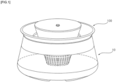
- the pet water dispenser may include a water tank or storage chamber 10 in which water is stored, a pump 20 (e.g., a submersible pump) installed in the water tank 10 to pump water stored in the water tank 10, a water supply pipe 25, and a water supply plate or upper plate 30 over which water supplied from the water supply pipe 25 flows.
- a pump 20 e.g., a submersible pump
- a water guide or a water receiver 50 may be provided between the water tank 10 and the water supply plate 30 to catch water falling from the water supply plate 30 and to discharge the water back to the water tank 10. Accordingly, water in the water tank 10 can be circulated through the pump 20, the water supply plate 30, and the water guide 50.
- a filter or filter assembly 40 may be installed or located in the water tank 10 to filter foreign substances in the water before the water flows into the pump 20.
- the water tank 10 may include a bottom plate 12 forming a bottom surface of the water tank 10 and a wall 11 surrounding an interior of the water tank 10 and an inner assembly 100.
- the wall 11 may extend from the base plate 12, and together the wall 11 and the bottom plate 12 may form a container of the water tank 10.
- the bottom plate 12 may also be referred to as an inner bottom of the water tank 10, and may be stainless steel or plastic.
- the inner assembly 100 may be detachably coupled to (e.g., simply mounted on) the water tank 10. When the inner assembly 100 is inserted or placed into the water tank 10, the inner assembly 100 and the water tank 10 may be coupled. A user may lift the inner assembly 100 to separate the inner assembly 100 from the water tank 10, and then replace or refill the water stored in the water tank 10 or clean the water tank 10.
- the inner assembly 100 may include the pump 20, the water supply pipe 25, the water supply plate 30, and the filter assembly 40.
- the pump 20, the water supply pipe 25, the water supply plate 30, and the filter 40 may be combined to form a single inner assembly 100.
- the water supply plate 30 may be configured to be removable from the inner assembly 100. The water supply plate 30 may be lifted up and removed to be cleaned, repaired, or swapped with another water supply plate 30 having a different height, shape, angle of inclination, material, etc.
- the pet water dispenser may also include an illumination assembly, a water level sensor, a water temperature sensor, a proximity sensor, a contamination level sensor, a water temperature maintenance device, and a sterilizing filter to be described later. Since the pump 20 may supply the water stored in the water tank 10 to the water supply plate 30, and the water supplied to the water supply plate 30 may be circulated back to the water tank 10, a power supply assembly capable of operating the pump 20 will be described with reference to Figures 4 to 9 .
- a pump may be provided inside a water tank, and a wire is directly connected to the pump and extended to an outside. Wires may be twisted and bent (and thus damaged) according to a movement of the water tank, and a connection portion of the pump and the wires may also be damaged by the tension applied to the wires, causing a short circuit. In addition, it is difficult to separate and assemble the water tank due to various wires connected to the inside and outside of the water tank, thereby making maintenance and repair difficult.
- the pet water dispenser of the present disclosure comprises a docking station 71 separate from the water tank 10 to which external power is applied, and a wireless communication device or assembly provided at the bottom plate 12 of the water tank 10 and electrically connected to the docking station 71.
- the wireless communication assembly may include a first wireless power communication device (e.g., a wireless power transmitter and/or a transceiver) 72 provided above the bottom plate 12 and a second wireless power communication device (e.g., a wireless power receiver 73 and/or a transceiver) provided under the bottom plate 12 and connected to the docking station 71 to minimize damage to an electrical wire 713 and prevent a malfunction or short circuit.
- a first wireless power communication device e.g., a wireless power transmitter and/or a transceiver
- a second wireless power communication device e.g., a wireless power receiver 73 and/or a transceiver
- the wireless power transmitter 72 and the wireless power receiver 73 may be positioned to align with each other, and positions of the bottom plate 12, wireless power transmitter 72, and wireless power receiver may be configured to prevent damage caused by an external impact, stabilize the water tank 10, and to protect the alignment between the wireless power transmitter and receiver 72 and 73.
- the electrical wire 713 may be drawn out from the docking station 71 to an external socket so that external power may be supplied to the docking station 71 to ultimately operate the pump 20.
- a manner in which external power is applied to the docking station 71 is not limited to the structure described in the above description or drawings.
- external power may be applied to the docking station 71 via wireless power transfer, and the electrical wire 713 may be omitted.
- the docking station 71 may be configured to apply external power to the water tank 10 and may be formed separately from the water tank 10.
- a base plate 18 may be provided under the bottom plate 12 and spaced away from the bottom plate 12, and the docking station 71 may be provided below both the base plate 18 and the bottom plate 12.
- the base plate 18 may also be referred to as an outer bottom of the water tank 10.
- the wall 11 may include an upper wall 11a and a container support 11b.
- the container support 11b may form a bottom edge of the wall 11 that extends past the rim of the bottom plate 12 to form the base plate 18.
- the base plate 18 may be positioned on the docking station 71, and a shape or curvature of the bottom surface of the base plate 18 may be configured to match or correspond with a shape or curvature of the top surface of the docking station 71.
- a recess corresponding to the step of the docking station 71 may be formed on the bottom surface of the base plate 18.
- a tilt or slope is formed on the upper surface of the docking station 71
- a tilt, slope, or contour having a same inclination of the tilt, slope, or contour of the docking station 71 may be formed on the bottom surface of the base plate 18. The base plate 18 may thus fit onto the docking station 71 to be secured to the docking station 71.
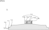
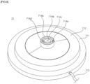
- the docking station 71 may include a plate-like disc or cylindrical docking station base 711.
- the docking station base 711 may form a basic structure or overall shape of the docking station 71. By having a disc-shaped structure, the docking station 71 and the water tank 10 can be rotatably engaged.
- the meaning of "circle” or “disc” or “cylinder” does not mean a geometrically perfect circle, but rather a shape that does not include a straight edge.
- the docking station base 711 may have a sufficient weight for balancing, and may be referred to as a weight or a main body of the docking station 71.
- An optional docking station guide 712 may be formed on the docking station base 711.
- the docking station guide or step 712 may guide and secure the water tank 10 and the docking station 71 to maintain a docked state.
- the base plate 18 coupled to the water tank 10 may be seated on the docking station 71 via the docking station guide 712 to dock or connect with a docking connection assembly or device 74.
- the docking station guide 712 may have a circular cylinder shape having a predetermined thickness similar to a shape of the docking station base 711 so that the water tub 10 coupled with the docking station 71 can be easily rotated.
- the docking station guide 712 may have a diameter smaller than a diameter of the docking station base 711.
- a top surface of the docking station guide 712 may include an inclined or curved surface.
- a thickness of the docking station guide 712 may thus be thicker toward a center axis of the docking station 71.
- the docking station 71 and the water tank 10 may thus be easily docked.
- a diameter of a lower portion of the container support 11b may be greater than a diameter of a docking terminal 714, and an appearance of the docking terminal 714 can be obscured by the wall 11.
- the docking station guide 712 may have a relatively small diameter and thickness as compared to the docking station base 711. Even if configurations and/or positions of the water tank 10 and the docking terminal 714 are not exactly matched, the base plate 18 may be guided along an upper surface of the docking station guide 712, and the lower wall 11b may be attached to a side surface of the docking station guide 712 so that an inner side of the container support 11b may be easily docked.
- a first guide magnet may be further included for easy docking of the docking station 71 and the water tank 10.
- a ring-shaped or annular first guide magnet may be provided inside the docking station guide 712, and a ring-shaped or an annular second guide magnet having a polarity opposite to that of the first guide magnet may be provided on the bottom surface of the base plate 18.
- a magnetic force generated by the first and second guide magnets having opposite polarities may help stabilize a docking between the water tank 10 and the docking station 71.
- a shape and position of first and second guide magnets are not limited to the annular shapes described in the above description.
- the docking station guide 712 may be formed integrally with the docking station base 711, or alternatively may be a laminated or stacked structure bonded to the docking station base 711.
- the docking terminal 714 may protrude upward from the upper surface of the docking station base 711 and/or an upper surface of the docking station guide 712.
- the docking terminal 714 may include a cylindrical first docking portion or ring 714a and a second docking portion or ring 714b that surrounds the first docking portion 714a at an outer side of the first docking portion 714a.
- the docking terminal 714 may further include a first electrode 714d provided on an inner side of the first docking portion 714a to connect to a second electrode 741c of the docking connection terminal 741 of the docking connection device 74 ( FIG. 7 ), and a third electrode 714e provided on an outer side of the first docking portion 714a to connect to a fourth electrode 741d of the docking connection terminal 741 ( FIG. 7 ).
- the first electrode 714d and the third electrode 714e may transmit external power supplied through the electrical wire 713, and may be electrode-coupled to the second and fourth electrodes 741c and 741 d, respectively, of the docking connection terminal 741.
- the docking terminal 714 may further include a third docking portion or cylinder 714c having a cylindrical shape and formed inside the first docking portion 714a.
- the first to third docking portions 714a, 714b and 714c form a basic structure of the docking terminal 714 and protect the first and third electrodes 714d and 714e.
- the first electrode 714d may be formed between an inner circumference or side of the first docking portion 714a and an outer circumference or side third docking portion 714c
- the third electrode 714e may be formed between an outer circumference or side of the first docking portion 714a and an inner circumference or side of the second docking portion 714b, as shown in FIG. 5 .
- the first electrode 714d and the third electrode 714e may extend upward from a bottom surface of the docking terminal 714.
- the first electrode 714d and the third electrode 714e may have a bent line shape or a curved shape, and may each have at least two linear sections having different slopes. Such a shape may provide elasticity and therefore stability to the first and third electrodes 714d and 714e.
- the first electrode 714d and the third electrode 714e may include a metal or other conductive material through which external power is directly transmitted. Therefore, there is a need to prevent electric shock and damage. Since the first and third electrodes 714d and 714e are provided between the first, second, and third docking portions 714a, 714b, and 714c, exposure to an outside and thus damage may be minimized.
- Heights of the first electrode 714d and the third electrode 714e may be configured to be lower than heights of the first to third docking portions 714a, 714b, and 714c to further protect the first and third electrodes 714d and 714e, minimize exposure, and ensure that the first and third electrodes 714d and 714e do not contact the water tank 10, which may prevent damage, electric shock, and corrosion.
- the structure of the docking terminal 714 is not limited to the structure in the above description and the drawings, and may be easily modified by a person skilled in the art.
- the first, second, and third docking portions 714a, 714b, and 714c may be formed in a square or rectangle shape to prevent rotation.
- the docking connection terminal 741 may rotate around the docking terminal 714, and thus the water tank 10 may rotate when it is docked on the docking station 71.
- the docking station guide 712 may have a predetermined thickness to function as a latching jaw and prevent the docked water tank 10 from being detached or removed from the docking station 71 during the rotation process.
- the docking station guide 712 may have a sloped upper surface having a greater thickness toward a center of the docking station 71, and a lesser thickness toward an outer perimeter. A portion of the bottom surface of the water tank 10 may be formed to match the upper surface of the docking station guide 712 to facilitate docking. The bottom surface of the water tank 10 may have a diameter that is larger than a diameter of the docking station guide 712, which may reduce friction during rotation.
- the first guide magnet which may have a ring shape, may be provided inside the docking station guide 712, and the second guide magnet, which may also have a ring shape, may be provided in the portion of the bottom surface of the water tank 10 that is docked on the docking station 71.
- the shape and position of the guide magnets are not limited to those described in the above description.
- a previous pet water dispenser may have electric wires directly connected to a pump and an electric outlet through a water tank.
- the pet could move or rotate the water dispenser, and the wire may be twisted or wound along with the water dispenser.
- the twisted or coiled wire is not only an obstacle over which people or dogs may trip, but it may also stimulate or provoke pets, which may react by biting and damaging the wires.
- the electrical wire 713 of the present disclosure may be connected to the docking station 71 so that external power is directly applied to the docking station 71. Since the docking station 71 and the water tank 10 are rotatable, a tensile force or stress applied to the electrical wire 713 may be dispersed by a rotation of the docking station 71 so as not to pull too much on the electrical wire 713.
- the water tank 10 may include walls 11a, 11b, and 11c forming a side of the water tank 10 and a bottom plate 12 provided on the lower side of the water tank 10.
- An upper wall 11a and a container support 11 b may form upper and lower sides of a main wall 11c, respectively.
- the upper wall 11a and the container support 11b may be an opaque material (e.g., stainless steel or pigmented plastic), and the main wall 11c may be formed of a transparent material (e.g., glass or plastic).
- the bottom plate 12 may be provided between the main wall 11c and the container support 11b.
- a container or internal space where water is stored may be formed by the upper and main walls 11a and 11c and the bottom plate 12, while a container support 11b may be provided below the bottom plate 12 to provide a dry or sealed space in which electronic devices to be described later are housed.
- the water tank 10 may be formed in a cylindrical or truncated cone shape having an inner diameter that decreases upward, but may be formed in various shapes without being limited thereto.
- the container support 11b of the water tank 10 may extend between the bottom plate 12 and a base plate 18 spaced downward from the bottom plate 12.
- the docking station 71 may be provided below the base plate 18.
- the base plate 18 may have a bottom surface having a shape or contour configured to match a shape or contour of the top surface of the docking station 71.
- a shape of the base plate 18 may correspond to a shape of the docking station base 711, and an inclination of the base plate 18 may correspond to an inclination of the docking station guide 712 so that a docking state of the water tank 10 may be stably maintained.
- the docking connection assembly or device 74 which includes the docking connection terminal 741 that electrically couples to the docking terminal 714, may be formed in a space defined by the bottom plate 12, the base plate 18, and the lower wall 11b.
- the docking connection device 74 may be docked with the docking station 71 to receive external power.
- the docking connection device 74 may include a docking connection terminal 741 protruding downward to match the docking terminal 714.
- the docking device 74 may have a concave portion or cavity formed to accommodate the docking terminal 714.
- a groove or recess 19 having a circular or cylindrical shape may be formed inside of a first connection protrusion 741a that extends downward from the docking connection device 74 inside of the cavity.
- the third docking portion 714c may be inserted into the groove 19, which may be formed at a center of the bottom surface the base plate 18.
- a space may be formed between the first connection protrusion 741a and a second connection protrusion 741b that extends downward from the docking connection device 74 and surrounds an outer side of the first connection protrusion 741a.
- the first docking connection portion 714a may be inserted into the space between the first and second connection protrusions 741a and 741b.
- the second docking connection portion 714b may be inserted into a space formed between the second connection protrusion 741b and an inner side of the cavity in the docking connection device 74.
- the docking station 71 and the docking connection device 74 may therefore be detachably coupled to each other, and a docking state of the water tank 10 may be easily maintained. Furthermore, the docking station 71 and the docking connection device 74 can be coupled at a lower center of the water tank 10.
- the second electrode 741c may be formed on a bottom surface of the first connection protrusion 741a
- the fourth electrode 741d may be formed on a bottom surface of the second connection protrusion 741b.
- the second electrode 741c and the first connection protrusion 741a may be inserted into a space between the third docking portion 714c and the first docking portion 714a to connect to the first electrode 714d.
- the fourth electrode 741d and the second connection protrusion 741b may be inserted into a space between the first docking portion 714a and the second coking portion 714b to connect to the third electrode 714e.
- power may be transmitted between the first electrode 714d and the second electrode 741c and between the third electrode 714e and the fourth electrode 741d.
- the second electrode 741c and the fourth electrode 741d may be annular electrodes, as opposed to the more linear first and second electrodes 714d and 714e. Thus, when the water tank 10 rotates, an electric connection between the first electrode 714d and the second electrode 741c and between the third electrode 714e and the fourth electrode 741d may be maintained.
- the second electrode 741c and the fourth electrode 741d may be provided at edges of the first connection protrusion 741a and the second connection protrusion 741b.
- the height of the first and second connecting protrusions 741a and 741b, including the second and fourth electrodes 741c and 741d attached thereto, may be configured to be smaller than a depth of the cavity formed in the docking connection terminal 74 to prevent electrode breakage, especially when the water tank 10 is not docked on the docking station 71.
- Configurations of the docking connection device 74 and the docking station 71 are not limited thereto, and the docking terminal 714 and the docking connection terminal 741 may be configured in various ways such that their shapes correspond to each other.
- a sensor device 86 and temperature control devices 81 and 82 may be provided in the space formed between bottom plate 12, base, 18 and lower wall 11b.
- a heat sink 84 and a heat radiating fan 83 may be further provided in the space between the bottom plate 12, base, 18 and container support 11b.
- the heat sink 84 may include a heat dissipation or diffusing plate and heat radiating fins.
- the sensor device 86, thermoelectric element 81, motor 82, heat sink 84, and heat radiating fan 83 may consume a relatively large amount of power. Accordingly, in order to efficiently transmit electric power from the docking station 71 to the docking connection device 74, the first and second electrodes 714d and 741c may be directly connected and contact each other, and the third and fourth electrodes 714e and 741d may be directly connected and contact each other.
- the external power applied through the docking station 71 and the docking connection terminal 74 can also supply power to the pump 20 via wireless power transfer or induction devices 72 and 73.
- Power transmission efficiency of wireless power transmission alone is about 70% as compared when there is also electrode coupling. Therefore, external power may be supplied to the heat sink 84, sensor device 86, and other high-consumption devices by the docking of the high-efficiency docking station 71, and the relatively low-power pump 20 may be powered by the wireless power transfer between the first and second wireless power transfer devices 72 and 73.
- power transfer efficiency can be optimized.
- the first wireless power transfer device 72 (e.g., a wireless power transmitter or transceiver) may be electrically connected to the docking connection device terminal 74 to transmit power to the second power transfer device 73 (e.g., a wireless power receiver or transceiver) to power the pump 20.
- the first and second wireless power transfer devices 72 and 73 may be connected to a power circuit device 715 on a printed circuit board (PCB) ( FIG. 4 ) instead of the electrical wire 713, which may prevent a short circuit or electric shock. Furthermore, shocks may be prevented because the inner assembly 100 of the water tank 10, which includes the pump 20, may not be connected to the electric wire 713.
- An alternative embodiment may be completely powered via the wireless power transfer device 72 or 73 instead of the first through fourth electrodes 714d, 741c, 714e, 741d.
- the wireless power transfer devices 72 and 73 may include a wireless power transmitter 72 provided under the bottom plate 12 and a wireless power receiver 73 provided in the inner assembly 100 to correspond to the wireless power transmitter 72.
- Wireless power transmission may control the wireless power transmitter 72 by the power circuit device 715 ( Fig. 4 ) that is electrically connected to the docking connection device 74.
- an induction current may be generated from electric current supplied to and a subsequent magnetic flux in the wireless power transmitter 72, so that power can be transmitted wirelessly.
- the wireless power transmitter and receiver 72 and 73 are not limited to inductive coupling based on magnetic induction phenomenon by a wireless power signal, but also an inductive coupling based on electromagnetic resonance phenomenon by wireless power signal of a specific frequency (i.e., via a Magnetic Resonance Coupling method).
- the wireless transmitter 72 may be provided in the base plate 18 of the water tank 10 so that it is positioned between the docking station 71 and the bottom plate 12 in the docked state. Referring to FIG. 3 , the wireless power transmitter 72 may transmit a wireless power transmission signal from a first accommodation or receiver space V1 formed between the bottom plate 12, the base plate 18, and the lower wall 11b. The wireless power transmitter 72 may be provided on or above the docking connection terminal 741.
- the bottom plate 12 may be formed with a protruding portion 121 protruding upward into the water tank 10, and the first accommodation space V1 may be formed in a cavity within the protruding portion 121 under the bottom plate 12.
- the first accommodation space V1 is not part of an interior of the water tank 10 that stores water, but rather a space formed underneath the water tank 10 so as to remain dry.
- Heat generation may be reduced by separating the docking station 71 and the wireless power transmitter 72 from each other by a considerable distance.
- the wireless power transmitter 72 may generate an electromagnetic field to wirelessly transmit power.
- a wireless power transmitter 72 There may be materials having high electric conductivity adjacent to a wireless power transmitter 72, and these materials may generate an electromagnetic field that interferes with an intended change in the electromagnetic field due of the wireless power transmitter 72, and unintended eddy currents may be generated. Unintended heat generation may occur due to these unintended eddy currents, diminishing efficiency of the WPT. External power may be directly applied to a plurality of electrodes, electric wires, or terminals having high electrical conductivity provided inside the docking station 71, and thus efficiency may diminish due heat generation from the eddy current.
- the pet water dispenser according to the present disclosure may separate the docking station 71 and the wireless power transmitter 72 from the base plate 18 by including accommodation space V1 formed in the cavity under the protrusion portion 121. Since the wireless power transmitter 72 may be provided in the first accommodation space V1, it is possible to minimize heat generation due to unintended eddy currents without creating a complicated shielding structure to limit an influence of the induced electromagnetic field or without adding a magnetic shielding film. In addition, stability of the WPT stability may be improved.
- coils of the wireless power transmitter 72 and the wireless power receiver 73 may be accurately aligned so that the magnetic field flux generated by the wireless power transmitter 72 may be accurately transmitted to the coil of the wireless power receiver 73.
- the coils of the wireless power transmitter 72 and the wireless power receiver 73 may be accurately aligned despite a rotation of the water tank 10 on the docking station 71 to prevent displacing the magnetic or electromagnetic field. While the wireless power transmitter 72 is kept a considerable distance away from the docking station 71, it is provided as close as possible to the wireless power receiver 73 during the docking state.
- the wireless power transmitter 72 may be provided adjacent to the bottom plate 12 and above or on the docking connection terminal 74.
- the wireless power 72 may be provided right under a top surface of the protruding portion 121, while the wireless power receiver 73 may be provided right above the top surface of the protruding portion 121 when the inner assembly 100 is inserted into and coupled to the water tank 10.
- Such a configuration can protect the wireless power transmitter 72 even when the water tank 10 is not docked onto the docking station 71 and improve stability of the WPT, as the wireless power transmitter 72 may be provided on the docking connection terminal 74 and separate from the docking station 71.
- the wireless power transmitter 72 when the wireless power transmitter 72 is provided in the docking station 71, the generated electromagnetic field may escape through the coils of the wireless power receiver 73 by the rotation of the docking station 71.
- the wireless power transmitter 72 if the wireless power transmitter 72 is tilted with respect to a ground or floor surface, the magnetic field may escape or propagate to the outer area of the wireless power receiver 73. Therefore, the wireless power transmitter 72 of the pet water dispenser according to the present disclosure may be separate from the docking station 71 to facilitate stable transfer of the magnetic field to the coil of the wireless power receiver 73 by fixing the wireless power transmitter 72 in the first accommodation space V1, thereby achieving excellent wireless power transmission.
- the wireless power receiver 73 may be provided above the bottom plate 12 in a second accommodation or receiver space V2 formed inside the inner assembly 100.
- the inner assembly 100 may include a concave portion or support cylinder 44b provided on a lower side of the inner assembly 100 to engage with the protrusion 121.
- the concave portion or support cylinder 44b may be formed of a tubular sidewall 44ba perpendicular to the bottom plate 12, and an upper plate 44bb may be provided to shield an upper surface of the sidewall 44ba.
- the protrusion 121 may be inserted into the support cylinder 44b to contact a bottom surface of the side wall 44ba, but does not contact the upper plate 44bb.
- the side wall 44ba may have a shape that corresponds to a shape of the protrusion 121.
- the sidewall 44ba and the protrusion 121 have a cylindrical shape, configurations are not limited thereto, and the sidewall 44ba and the protrusion 121 may have, e.g., a truncated cone shape, or may have a square shape to prevent rotation of the inner assembly 100 on the protrusion 121.
- the inner assembly 100 may include a filter or filter assembly 40 that includes a first filter 42 surrounding a second filter 44, and the second filter 44 may surround the pump 20.
- the second filter 44 may have a tubular outer wall 442 perpendicular to the bottom plate 12 and a support plate 444 partitioning a lower side of the filter into the lower side.
- the outer wall 442 may extend to couple to the sidewall 44ba of the concave portion 44b to define sides of the second accommodation space V2.
- the pump 20 may be provided on the support plate 444, and the upper plate 44bb may extend between sides of the outer wall 442 to shield a lower opening of the second filter 44 and enclose the second accommodation space V2 to prevent water from seeping in.
- the second accommodation space V2 may therefore be formed between the upper plate 44bb, the support plate 444, and the outer wall 442, and the wireless power receiver 73 may be provided in the second accommodation space V2.
- the wireless power transmitter 72 may thus be provided in the projection 121, and the wireless power receiver 73 may be provided on the support cylinder 44b that engages with the projection 121.
- the wireless power receiver 73 may be positioned between the support cylinder 44b and the second filter 44 to be safely protected from an external environment, and the distance between the wireless power transmitter 72 and the wireless power receiver 73 can be minimized.
- the first receiver space V1 and the second receiver space V2 in which the wireless power transmitter and receiver 72 and 73 are respectively provided may also be effectively cooled by a colder temperature of the water surrounding the protrusion 121 and the filter assembly 40.
- the wireless power receiver 73 may be configured such that the inner filter assembly 100 is installed in the water tank 10 (see FIG. 2 ) in a state in which a lower filter cover 43 covers the protruding portion 121.
- the first accommodation space V1 and the second accommodation space V2 may be "closed spaces;" i.e., a space where side surfaces, a top surfaces, and a bottom surface are all shielded to form a space physically separated and sealed off from other areas.
- the first accommodation space V1 may be shielded by the protruding portion 121 at the sides and on top, and a bottom surface may be shielded by the PCB of the power circuit device 715 and/or the terminal connection device 74.
- the second accommodation space V2 may be formed by the outer wall 442, the support plate 444, and the upper plate 44bb to form a closed space.
- the first and second accommodation spaces V1 and V2 may be sealed to prevent penetration of moisture and external contaminants, improving the stability of WPT.
- the wireless power receiver 73 once receiving electric power from the wireless power transmitter 72, may supply electric power to the electric components (i.e., pump 20, etc.) inside the inner assembly 100.
- the inner assembly 200 may further include an auxiliary battery B powered by the wireless power receiver 73 so that the pump 20 may work even if the water tank 10 is separated from the docking station 71, and also so that a use life is not restricted by a length of the electrical wire 713.
- the auxiliary battery B may be provided inside the inner assembly 100 and may be electrically connected to the wireless power receiver 73. Once the auxiliary battery B has a charge, the wireless power receiver 73 can receive power from the auxiliary battery or battery B instead of the docking station 71 to supply electric power to any electric components (e.g., pump 20) included in the inner assembly 100. The wireless power receiver 73 can then further transmit power back to the wireless power transmitter 72 (or the auxiliary batter B may further power a reverse wireless power transmitter, which transmits power to a reverse wireless power receiver, described below) to power components (e.g., controller, fan, sensors, or thermoelectric element 81), so that even if the electrical wire 713 is disconnected, usage can be maximized.
- the wireless power receiver 73 can receive power from the auxiliary battery or battery B instead of the docking station 71 to supply electric power to any electric components (e.g., pump 20) included in the inner assembly 100. The wireless power receiver 73 can then further transmit power back to the wireless power transmitter 72 (or the auxiliary batter B
- Auxiliary battery B can be connected and recharged when the electrical wire 713 is reconnected.
- the auxiliary battery B may be provided on an upper filter cover 46 that hermetically seals an upper portion of the pump 20 to create another sealed space shielded from water. Thus, a short circuit, electric shock, and damage to the auxiliary battery B may be prevented.
- owners may disconnect the electrical wire 713 when pets drink from the pet water dispenser, eliminating the case where a pet chews or tears the electrical wire 713. Owners may further reconnect the electrical wire 713 in a space away from pets when the pet water dispenser is not in use.
- a control unit or controller C may be provided in the same sealed space S as the auxiliary battery B, and the wireless power receiver 73 may be connected to the controller C so that power control can be effectively performed.
- the auxiliary battery B may be charged while the docking station 71 is coupled to the water tank 10, and the controller C may control the charging of the auxiliary battery B.
- the pet water dispenser may include a reverse or second wireless power receiver and a reverse or second wireless power transmitter, in addition to the wireless power transmitter 72 and the wireless power receiver 73.
- the reverse wireless power transmitter may align with and transmit power to the reverse wireless power receiver.
- the configuration and operation principle of the reverse wireless power transmitter and the receiver may be the same as between the wireless power transmitter and receiver 72 and 73.
- the reverse wireless power transmitter may be provided in the second accommodation space V2 near the wireless power receiver 73.
- the reverse wireless power receiver may be provided in the first accommodation space V1 with the wireless power transmitter 72.
- the auxiliary battery B may be electrically connected to the wireless power transmitter 73 and the reverse wireless power receiver.
- the wireless power transmitter and receiver 72 and 73 may transmit external power from the electrical wire 713 to the inner assembly 100
- the reverse wireless power transmitter and receiver may transmit power from the auxiliary battery B back down to the base plate 18.
- the filter 40 may purify and/or filter water supplied by the pump 20.
- the first filter 42 may be a strainer (e.g., a mesh strainer or a truncated conical strainer) having sufficient rigidity and formed with a large number of through holes on its side wall.
- the first filter 42 may include a lower filter cover 43 formed separately and coupled to a lower surface of the first filter 42, or alternatively formed as a single body with the filter 42.
- the lower filter cover 43 may cover the protrusion 121 described above, and may fit within the support cylinder 44b.
- the lower filter cover 43 may have a shape corresponding to an outer surface contour of the protrusion 121.
- the second filter 44 may include the outer wall 442, which includes a plurality of through holes 441, and an inner wall 443 spaced apart from the outer wall and having a plurality of through holes formed therein.
- a filter material e.g., a carbon filter 45
- the second filter 44 and the support cylinder 44b may be separately manufactured and then assembled, or alternatively integrally formed as a single piece.
- the pump 20 may be provided in a hollow formed inside the inner wall 443 of the second filter 44 above the support cylinder 44b. Water that has passed through the first and second filters 42 and 44 can be sucked into the pump 20 through the through holes formed in the inner wall 443 of the second filter 44 and discharged to the water supply pipe 25. Efficiency may be improved because a separate structure to fix the pump 20 at a predetermined position is not required, as the inner wall 443 and the support plate 444 may support the pump 20.
- a first ultraviolet (UV) filter or light 47 to sterilize water introduced into the pump 20 may be installed or located under a lower side or end of the second filter 44 and coupled to the sidewall 44ba of the support cylinder 44b.
- a second UV filter or light 48 may be provided between a lower end of the first filter 42 and the lower filter cover 43, and may also couple to the sidewall 44ba of the support cylinder 44b.
- the upper filter cover 46 may be provided on upper ends of the first and second filters 42 and 44.
- the water supply pipe 45 may penetrate the upper filter cover 46, which may seal the upper portion of the pump 20 and cover the first and second filters 42 and 44.
- the water supply pipe 25 may be arranged in a vertical direction, and may include a water inlet 26 formed in a lower portion and a water outlet 27 formed in an upper portion. Water discharged from the pump 20 may flow through the water inlet 26 and may be discharged through the water outlet 27.
- An water supply plate 30 ( FIG. 2 ) may be a plate having a smooth upper surface, and a water supply hole 32 may be formed at a center of the water supply plate 30.
- a boss may protrude downward from the water supply plate 30, and the water supply hole 32 may penetrate through the boss.
- a plate support may be provided below and support the water supply plate 30, and the plate support may be supported by a light emitting device support 62 or a support 63 of an illumination assembly 60 provided between the water supply plate 30 and a partition plate 38.
- the support 63 may serve as a light diffuser and may also be referred to as a light guide or light guide plate.
- the water supply pipe 25 may penetrate through a partition plate 38 located below the plate support 36 so that the water outlet 27 communicates with the water supply hole 32 of the water supply plate 30.
- a water guide or a water receiver 50 may be provided below the water supply plate 30 and is configured to cover an opened upper side of the water tank 10 so as to receive water dropped from an edge of the water supply plate 30 and guide the received water back to the water tank 10.
- the water guide 50 may also be referred to as a drip tray or a splash guard.
- the water guide 50 may include an outer guide wall 51 forming an outer rim of the water guide 50 and an inner guide wall 53 forming an inner rim to define a drain passage 52 between the outer wall 51 and the inner wall 53.
- a bottom wall 55 may extend between the outer and inner guide walls 51 and 53, and may include a discharge hole through which water in the drain passage 52 may discharge to the water tank 10
- a chamber or a space S accommodating the auxiliary battery B and the controller C may be formed between the upper filter cover 46, the inner wall 53 of the water guide 50, and the partition plate 63.
- the space S may be a sealed or dry space sealed from water stored in the water tank 10.
- the bottom wall 55 may cover a lower portion of the water guide 50 so that the bottom wall 55 does not contact the first and second filters 42 and 44.
- the upper filter cover 46 may be omitted. Accordingly, the filter 40, the pump 20, the water supply pipe 25, the water supply plate 30, the illumination device 60, and the water guide 50 may be combined or assembled to be integral with each other to form a single inner assembly 100. Since the inner assembly may be separated from the water tank 10, cleaning of the water tank 10 and the repair work of various components can be easily performed.
- thermoelectric element or plate 81 to keep the temperature of the water stored in the water tank 10 at a predetermined temperature may be provided below the bottom plate 12 of the water tank 10.
- the thermoelectric element 81 may be a Peltier device or a thermoelectric cooler (TEC).
- a heat radiating fan 83 which is operated by a motor 82, and a heat radiating plate or heat sink 84 may be installed around the heat radiating fan 83.
- the heat sink 84 may also be referred to as a heat dissipation plate.
- a water temperature sensor 85 (e.g., thermometer) may be provided in a space inside the protrusion 121 so that the temperature of the water in the water tank 10 may be sensed. Since the water temperature sensor 85 may have a large contact area with the water stored in the water tank 10, and since the water temperature sensor 85 may be installed inside the protrusion 121 where water moves toward the pump 20, the temperature sensor 85 may accurately sense a temperature of the water.
- the bottom plate 12 may be made of a material having a high heat thermal conductivity, such as metal (e.g., stainless steel). Alternatively, the water temperature sensor 85 may partially protrude above the bottom plate 12 into the container of the water tank 10 to accurately measure a temperature of the water. When the sensed temperature is not within a set range, the thermoelectric element 81 may be operated to cool or heat the water, and a heat transfer occurs between the thermoelectric element 81 and the heat sink 84.
- thermoelectric element 81 There may also be another temperature sensor to measure a temperature of the thermoelectric element 81 and/or the heat sink 84.
- the motor 82 may be operated to drive (i.e., rotate) the heat radiating fan 83.
- thermoelectric element 81 When the heat dissipation fan 83 is rotated, external air flows into the heat sink 84 through ventilation holes 181 formed in the base plate 18, and then is discharged to an outside through an outermost portion of the ventilation holes 181.
- the heat sink 84 and the thermoelectric element 81 may thus be cooled.
- a mounting space may be formed between an outer surface of the container support 11b and an inner wall provided in an inner space of the container support 11b to be spaced apart from an inner surface of the container support 11b.
- the mounting space may be formed by recessing an upper surface that extends between the inner wall and the container support 11b.
- a water level sensor 86 may be provided in the mounting space.
- the water level sensor 86 may be a load sensor or strain gauge for sensing a weight of the water applied to the bottom plate 12.
- a warning lamp or light which may be or include a ring-shaped light emitting diode, may be attached to a lower edge of the lower wall 11b. When the water level in the water tank 10 detected by the water level sensor 86 is lower than a predetermined value, the warning light may emit light to inform the user of a lack of water or to refill the water tank 10.
- an optional base leg or support capable of adjusting a height of the water tank 10 above a ground or floor surface may be provided.
- the base leg may adjust according to an inclination of the water tank 10 sensed by the gyro sensor. For example, a height of the leg can be adjusted to correct a tilting of the water tank 10.
- the controller C may receive a signal sensed by the water level sensor 86 to calculate a water level value. When the calculated water level value is equal to or lower than a predetermined water level value, the controller C may activate the warning light, and an operation of the pump 20 may be controlled to be stopped.
- the proximity sensor may sense how close a pet is to the pet water dispenser.
- the pump 20 may be operated.
- the controller C may stop an operation of the pump 20 when it is determined that a pet is not approaching within the predetermined distance range.
- the controller C may calculate a movement of the pet based on continuous signals from the proximity sensor, and so the controller C may control the pump 20 to be operated only when the pet continues to approach by a predetermined distance or more within the predetermined distance range.
- a pumping capacity or rate of the pump 20 may be increased so as to correspond to a number of approaching pets.
- a contamination sensor provided in the water tank 10 may sense a contamination level of the water stored in the water tank 10. When the contamination sensor senses a contamination level of the water, it may transmit a signal to the controller C. When the controller C determines that a contamination degree is equal to or greater than a predetermined contamination value based on the received signal, the controller C may control the UV filters 47 and 48 to operate and sterilize the water. The controller C may also stop the operation of the pump 20 and control the warning light 91 to emit a light or a warning alarm to produce a warning sound.
- an operation time of the pump 20 according to the signal of the proximity sensor may be continuously stored and analyzed, the controller may predict a pet's consumption and operate the pump 20 accordingly.
- the pump 20 can be operated so that a water supply amount corresponding to a predicted water supply time (e.g., noon) or time period (e.g., every two hours) may be provided.
- a predicted water supply time e.g., noon
- time period e.g., every two hours
- thermoelectric element 81 and/or the heat radiation fan 83 may be operated to cool the water.
- a temperature of the thermoelectric element 81 may be determined by a thermoelectric element temperature sensor of the thermoelectric element 81.
- the motor 82 may be operated to rotate the heat radiation fan 83 so that the heat sink 84 can cool the thermoelectric element 81.
- the height of one or more supports or legs or a pedestal provided below the water tank 10 may be adjusted to restore the water tank 10 to a normal (or flat) inclination.
- Embodiments disclosed herein may be implemented as a liquid dispenser that supplies drinking water to an animal such as a pet.
- the liquid dispenser may be used in a zoo to supply drinking water to animals kept in a zoo, research areas, wildlife preservation areas, etc.
- a thickness of some layers and regions may be enlarged or exaggerated. It will also be understood that when a layer, film, region, plate, etc. is referred to as being “on” or “over” (or “under” or “underneath”) another portion, there may be a layer, film, region, plate, etc. therebetween. Conversely, when a layer, film, region, plate, etc. is described as “directly over” (or “directly under”) another portion, there may be no other layer, film, region, plate, etc. therebetween.
- Embodiments disclosed herein may be implemented as a pet water dispenser or water supply device that can securely transmit wireless power by protecting a wireless power transmission unit or a wireless power transmitter.
- the pet water dispenser may provide a device capable of minimizing heat generation by a wireless power transmission unit to maintain efficiency.
- the pet water dispenser may be capable of preventing electric shock and protecting the health of pets safely using the pet water dispenser.
- the pet water dispenser may be capable of preventing damage to a connection part of the electric wire by movement of the pet water dispenser, thereby improving durability. Electric shock to pets may be further prevented by providing a docking station that can be disconnected.
- the pet water dispenser may be capable of stably supplying electric power without damaging electric wires or electric parts even if a water tank is rotated or moved due to an impact applied to a pet water dispenser.
- the pet water dispenser may have a water tank easily separated from an inner assembly, can be easily maintained, and can prevent electric shock.
- the pet water dispenser may protect a wireless power transmission unit or wireless power transmitter from an external impact and may have excellent wireless power transmission stability.
- a useable area of the pet water dispenser may not be limited to a length of the electric wire, and instead may be enlarged.
- the pet water dispenser may be operated by external power or internal power, and may dock onto a docking station to deliver power and transfer external power from an external power supply to create internal power via a power supply apparatus or device.
- the power supply apparatus may include a wireless power transmission unit or a wireless power transmitter, a wireless power reception unit or a wireless power receiver, and a docking station, and the docking station and the wireless power transmission unit can be separated.
- the docking station may receive external power from an external power supply.
- the docking station may be provided below a bottom plate of a water tank when the pet water dispenser is docked on the docking station.
- the wireless power transmission unit may be electrically connected to the docking station, and may be provided at a lower side of the bottom plate and spaced apart from the docking station.
- the wireless power reception unit may be matched (i.e., aligned with) and electrically connected to the wireless power transmission unit, and may be provided on the bottom plate.
- the wireless power transmission unit may be provided in a first accommodation or receiving space formed above the docking station.
- a base may be provided below the bottom plate, and the first accommodation space may be formed between the bottom plate and the base.
- the docking station may be provided below the base.
- the bottom plate may have a protruding portion that protrudes upward, and the wireless transmission unit may be provided inside the protruding portion.
- the wireless power reception unit may be provided in a second accommodation or receiving space formed in an inner assembly.
- the inner assembly may include a tubular filtration filter or filter to receive the pump, and a concave portion or cylinder support that shields a lower opening of the filter via an upper plate.
- the second accommodation space may be formed between the pump and the upper plate.
- the wireless power reception unit and the wireless power transmission unit may be aligned with each other.
- the first accommodation space and the second accommodation space may be closed spaces.
- the protrusion may be inserted into a bottom surface of the concave portion.
- Embodiments disclosed herein may be implemented as a pet water dispenser, which may include a first wireless power device, such as a wireless transmission unit, electrically coupled to the docking station, and a second wireless power device, such as a wireless reception unit, electrically coupled to the first wireless power device.
- the first wireless power device may be provided in a first accommodation space spaced apart from the docking station, and the second wireless power device may be provided in a second accommodation space spaced above the first accommodation space.
- the first accommodation space may be provided above the docking station.
- the pump may be connected to the second wireless power device.
- a water tank may include a base spaced apart from a bottom plate, the first accommodation space being formed between the bottom plate and the base, and the docking station being provided below the base.
- the second accommodating space may be spaced apart from an upper side of the bottom plate.
- the first accommodation space and the second accommodation space may be closed spaces.
- a shielding film may be formed on a lower surface of the first accommodation space and an upper surface of the second accommodation space.
- the bottom plate of the water tank may be formed with a protruding portion or protrusion that protrudes or extends upward, and the first accommodating space may be provided inside the protruding portion while the second accommodating space may be provided above the protruding portion.
- a filter may include a filtration filter for receiving the pump, and the second accommodation space may be formed inside the filtration filter or between a second filtration filter and a support cylinder.
- the support cylinder may form a recess, and can be fitted into the protrusion of the water tank.
- a power supply of a pet water dispenser may include a docking station, a first wireless power device (e.g., wireless power transmitter), a second wireless power device (e.g., wireless power receiver), and a secondary battery or an auxiliary battery.
- the docking station may be detachable from the water tank.
- the secondary battery may be connected to the first wireless power device or the second wireless power device.
- the auxiliary battery may be electrically connected to the wireless power receiver.
- a base may be provided below a bottom plate of the water tank.
- the wireless power transmitter may be provided in a first accommodation space formed between the bottom plate and the base, and the docking station may be provided below the base.
- the docking station may include a plate-shaped docking station base and a docking terminal protruding upward from an upper surface of the docking station base.
- a docking connection terminal may be electrically connected to the wireless power transmitter.
- the docking connection terminal may be provided between the bottom plate and the base, and the docking terminal of the docking station may be inserted into a circular hole of the base to connect to the docking connection terminal.
- the docking station may be electrode-coupled to the docking connection terminal.
- the inner assembly may include a tubular filtration filter or filter that receives the pump, a tubular concave wall or support cylinder, and an upper plate shielding an upper surface of the concave wall.
- a lower opening of the filtration filter may be connected to the upper surface of the concave wall and may further include a shielding concave portion.
- a second accommodation space may be formed between the pump and the upper plate, and the wireless power receiver may be provided in the second accommodation space.
- the wireless power transmitter may be provided in the first accommodation space and align with the wireless power receiver, which is formed in the second accommodation space.
- the auxiliary battery may be electrically connected to the wireless power receiver and the wireless power transmitter.
- the docking station base and the docking terminal may be rotatable in a cylindrical shape.
- the docking connection device may be configured to allow the water tank to be docked and electrically connected to the docking station.
- the docking connection device may be provided between the bottom plate of the water tank and the base, and the first wireless power device may be connected to the docking connection device.
- the docking station may be electrode-coupled to the docking connection device.
- the docking station may include a first connection terminal projecting upwardly, and the docking connection device may include a second connection terminal recessed to match the first connection terminal.
- the first wireless power device may include a wireless power transmitter, the second wireless power device may include a wireless power receiver, and the secondary or auxiliary battery may be connected to the first and/or second wireless power device.
- the first wireless power device may include a first wireless power transmitter and a first (or reverse) wireless power receiver
- the second wireless power device may include a second wireless power receiver aligned with the first wireless power transmitter, and a second (or reverse) wireless power transmitter matched with the first wireless power receiver.
- the auxiliary battery may be connected to the second wireless power device.
- the pet water dispenser may have a rotatable docking station.
- Wireless power transmitters may be provided in a separate space and separated from the docking station.
- a power supply apparatus may include a wireless power transmission unit, a wireless power reception unit, and a detachable docking station.
- the wireless power transmission unit may be provided below a bottom plate of a water tank and outside the docking station to be stably maintained.
- a wire fixed to an external power source may be drawn out from the docking station, and the docking station may be rotatably coupled, thereby reducing wire damage.
- a water supply plate having a water supply hole from which water is supplied may communicate with a water supply pipe connected to the pump.
- the power supply apparatus may include a docking station to which external power is applied, a wireless power transmission unit provided under a bottom plate of the water tank and electrically connected to the docking station, and a wireless power reception unit provided on the bottom plate of the water tank.
- the pet water dispenser may include an auxiliary battery electrically connected to an electric component and the wireless power transmission device.
- Embodiments disclosed herein may be implemented as a pet water dispenser that separates a wireless power transmission unit or wireless power transmitter from a docking station, thereby minimizing heat generation by eddy currents in a power system configuration included in the docking station, thereby maintaining efficiency. It is possible to effectively minimize heat generation due to the eddy currents in the surroundings without separately forming a complex shielding film structure.
- the wireless power transmitting unit may be provided outside and separate from the docking station, the docking station can stably transmit wireless power.
- a secondary battery may operate the pet water dispenser when the docking station from which the wire is drawn out is removed and separated from a base of the water tank, thereby preventing electric shock that may occur during chewing or biting of the wire by the animal.
- the pet water dispenser can therefore be used safety.
- the pet water dispenser can rotate on the docking station from which the electric wire is drawn, it is possible to reduce damage to a connecting portion of the electric wire and reduce tension applied to the electric wire.
- External power may be applied to the docking station to minimize deformation and damage of the wire even if there is a rotation or movement of the water tank. Partial breakage of the electric wire where the electric wire connects to the docking station may be prevented.
- the pet water dispenser may include a wireless power transmission unit or transmitter provided on a lower side of a bottom plate and a wireless power receiving unit or receiver provided on an upper side of a bottom plate, the pet water dispenser does not include electric wires exposed to water, thereby preventing short circuit and electric shock. Since there is no electric wire to transmit electric power from the water tank to the inner assembly and/or pump, it is easy to separate and assemble the water tank and the inner assembly, simplifying maintenance and cleaning.
- the wireless power transmission unit Since the wireless power transmission unit is provided below the bottom plate separately from the docking station, the wireless power transmission unit may be prevented from being damaged by an external impact, and the arrangement of the wireless power transmission unit may be fixed so that the stability of wireless power transmission can be improved. Since an auxiliary battery may supply its own power even if no external power is supplied, a useable area of the pet water dispenser is not limited to a length of the electric wire, thereby maximizing utility and stability of an operation of the pump.
- Embodiments disclosed herein may be implemented as a liquid dispenser comprising a tank including a bottom and a wall surrounding the bottom, an inner assembly having a pump and configured to be coupled to the tank, a docking station configured receive external power, the docking station being detachable from the tank, a wireless power transmitter configured to receive power from the docking station, the wireless power transmitter being provided below the bottom of the tank and spaced apart from the docking station, and a wireless power receiver configured to induce power in response to a magnetic flux generated from the wireless power transmitter and to supply power to the pump of the inner assembly.
- the wireless power transmitter may be provided in a first space formed above the docking station.
- the bottom of the tank may include an inner bottom and an outer bottom.
- the docking station may be rotatably coupled to the outer bottom of the tank.
- the outer bottom of the tank may be provided below the inner bottom of the tank, and the first space may be formed between the outer and inner bottoms of the tank.
- the bottom of the tank may be formed with a projection protruded upward, and the wireless power transmitter may be provided inside the projection.
- the wireless power receiver may be provided in a second space formed in the inner assembly.
- the inner assembly further may include a filter surrounding the pump and a wall and an upper plate provided on an upper end of the wall to form a chamber.
- a bottom of the filter may be coupled to at least one of the wall or the upper plate.
- a first space may be formed between the pump and the upper plate.
- a second space formed above the docking station and the first space may be spaces that may be shielded from liquid stored in the tank.
- a protrusion formed from the bottom of the tank may be inserted into the chamber of the inner assembly.
- Embodiments disclosed herein may be implemented as a liquid dispenser, comprising a tank including a bottom and a wall surrounding the bottom, an inner assembly including a pump, the inner assembly being configured to be coupled to the tank, a docking station configured to receive external power, the docking station being detachable from the bottom of the tank, a first wireless power transmitter configured to selectively connect to the docking station to receive power from the docking station, a first wireless power receiver configured to induce power in response to a magnetic flux generated from the wireless power transmitter and supply power to the pump in the inner assembly, the first wireless power receiver being provided in the inner assembly, and a battery configured to receive power from the wireless power receiver, the battery being provided in the inner assembly.
- the bottom of the tank may include an inner bottom and an outer bottom, and the first wireless power transmitter may be provided in a first space formed between the inner and outer bottoms of the tank.
- the docking station may include a base and a first terminal protruded upward from the base.
- the outer bottom may include a second terminal configured to insert into the first terminal, wherein, when the first terminal may be inserted into the second terminal, the first terminal receives external power, the second terminal receives power from the first terminal, and the first wireless power transmitter receives power from the second terminal.
- the inner assembly may further include a filter assembly surrounding the pump and a chamber formed by a wall and an upper plate coupled to the filter assembly.
- a first space may be formed between the pump and the upper plate.
- the first wireless power receiver may be provided in the first space.
- a second wireless power transmitter and a second wireless power receiver may be provided.
- the first wireless power transmitter and the second wireless power receiver may be provided in a second space provided in the bottom of the tank, and the first wireless power receiver and the second wireless power transmitter may be provided in the first space.
- the first wireless power transmitter may be aligned with the first wireless power receiver and the second wireless power transmitter may be aligned with the second wireless power receiver.
- the battery may be electrically connected to the first wireless power receiver and the second wireless power transmitter.
- Embodiments disclosed herein may be implemented as a liquid dispenser comprising a tank including an inner bottom and an outer bottom spaced apart from an inner bottom, an inner assembly configured to receive and discharge liquid from the tank, the inner assembly being coupled to the tank at a position above the inner bottom, and a docking station configured to supply power to the inner assembly, the docking station being coupled to the outer bottom.
- the docking station may be stepped, an upper surface of the docking station may have a shape that may be curved, and a bottom surface of the outer bottom of the tank may be shaped to correspond to the shape of the upper surface of the docking station.
- the docking station may be configured to rotate with respect to the outer bottom of the tank.
- first, second, third, etc. may be used herein to describe various elements, components, regions, layers and/or sections, these elements, components, regions, layers and/or sections should not be limited by these terms. These terms are only used to distinguish one element, component, region, layer or section from another region, layer or section. Thus, a first element, component, region, layer or section could be termed a second element, component, region, layer or section without departing from the teachings of the present invention.
- spatially relative terms such as “lower”, “upper” and the like, may be used herein for ease of description to describe the relationship of one element or feature to another element(s) or feature(s) as illustrated in the figures. It will be understood that the spatially relative terms are intended to encompass different orientations of the device in use or operation, in addition to the orientation depicted in the figures. For example, if the device in the figures is turned over, elements described as “lower” relative to other elements or features would then be oriented “upper” relative to the other elements or features. Thus, the exemplary term “lower” can encompass both an orientation of above and below. The device may be otherwise oriented (rotated 90 degrees or at other orientations) and the spatially relative descriptors used herein interpreted accordingly.
- Embodiments of the disclosure are described herein with reference to cross-section illustrations that are schematic illustrations of idealized embodiments (and intermediate structures) of the disclosure. As such, variations from the shapes of the illustrations as a result, for example, of manufacturing techniques and/or tolerances, are to be expected. Thus, embodiments of the disclosure should not be construed as limited to the particular shapes of regions illustrated herein but are to include deviations in shapes that result, for example, from manufacturing.
- any reference in this specification to "one embodiment,” “an embodiment,” “example embodiment,” etc. means that a particular feature, structure, or characteristic described in connection with the embodiment is included in at least one embodiment of the invention.
- the appearances of such phrases in various places in the specification are not necessarily all referring to the same embodiment.
Landscapes
- Engineering & Computer Science (AREA)
- Life Sciences & Earth Sciences (AREA)
- Environmental Sciences (AREA)
- Power Engineering (AREA)
- Biodiversity & Conservation Biology (AREA)
- Animal Husbandry (AREA)
- Computer Networks & Wireless Communication (AREA)
- Chemical & Material Sciences (AREA)
- Hydrology & Water Resources (AREA)
- Water Supply & Treatment (AREA)
- Environmental & Geological Engineering (AREA)
- Organic Chemistry (AREA)
- Health & Medical Sciences (AREA)
- Toxicology (AREA)
- Mechanical Engineering (AREA)
- Chemical Kinetics & Catalysis (AREA)
- General Engineering & Computer Science (AREA)
- Public Health (AREA)
- Birds (AREA)
- Feeding And Watering For Cattle Raising And Animal Husbandry (AREA)
Description
- A liquid dispenser to supply liquid to an animal, e.g., a pet, is disclosed herein.
- In recent years, the population of people raising a pet has increased, in addition to attachment and interest in pets. Like most animals, pets must drink water to survive and maintain a biorhythm. Since pets are often left alone and since communication with their owners is difficult, the demand for pet water dispensers or water supply devices has increased.
-
US Publication Nos. 2015/0313180 ,2012/0216751 , and2014/0053781 andEuropean Patent No. 3315022 disclose a drinking bowls for pets. However, such drinking bowls have various disadvantages, which the present disclosure solves. - The above references are incorporated by reference herein where appropriate for appropriate teachings of additional or alternative details, features and/or technical background.
-
EP 3 520 607 A1 relates to a water pump and an aquarium equipment that includes the water pump. The water pump includes a stator, a rotor assembly, an impeller, and a power generation induction module. The stator includes a U-shaped iron core and a coil winding wound around the U-shaped iron core. The coil winding is connected to an external power source. The rotor assembly includes a rotating shaft and a permanent magnet rotor. The impeller is connected to the rotating shaft or to the permanent magnet rotor. The power generation induction module is spaced apart from the rotor assembly. The rotor assembly and the power generation induction module are both disposed within a range of a magnetic field at an opening of the U-shaped iron core. The power generation induction module is electrically connected to an electric equipment. - The invention is specified in the independent claim 1. Further aspects of the invention are defined in the dependent claims.
- The embodiments will be described in detail with reference to the following drawings in which like reference numerals refer to like elements wherein:
-
FIG. 1 is a perspective view showing an appearance of a pet water dispenser according to an embodiment; -
Fig. 2 is a cross-sectional view of the pet water dispenser shown inFig. 1 ; -
FIG. 3 is a cross-sectional view illustrating the combination of a water tank and an inner assembly according to an embodiment; -
FIG. 4 is a cross-sectional view of the water tank according to an embodiment; -
FIG. 5 is a sectional view of a docking station according to an embodiment; -
FIG. 6 is a perspective view of the docking station according to an embodiment; -
FIG. 7 is a sectional view of a filter and a pump according to an embodiment; and -
FIG. 8 is a cross-sectional view of the filter and the pump shown inFIG. 7 . - Referring to
Figures 1 and2 , a circulation structure of the pet water dispenser according to an embodiment will be described. The pet water dispenser may include a water tank orstorage chamber 10 in which water is stored, a pump 20 (e.g., a submersible pump) installed in thewater tank 10 to pump water stored in thewater tank 10, awater supply pipe 25, and a water supply plate orupper plate 30 over which water supplied from thewater supply pipe 25 flows. - A water guide or a
water receiver 50 may be provided between thewater tank 10 and thewater supply plate 30 to catch water falling from thewater supply plate 30 and to discharge the water back to thewater tank 10. Accordingly, water in thewater tank 10 can be circulated through thepump 20, thewater supply plate 30, and thewater guide 50. In addition, a filter or filter assembly 40 may be installed or located in thewater tank 10 to filter foreign substances in the water before the water flows into thepump 20. - Referring to
Figures 2-3 , thewater tank 10 may include abottom plate 12 forming a bottom surface of thewater tank 10 and awall 11 surrounding an interior of thewater tank 10 and aninner assembly 100. Thewall 11 may extend from thebase plate 12, and together thewall 11 and thebottom plate 12 may form a container of thewater tank 10. Thebottom plate 12 may also be referred to as an inner bottom of thewater tank 10, and may be stainless steel or plastic. - The
inner assembly 100 may be detachably coupled to (e.g., simply mounted on) thewater tank 10. When theinner assembly 100 is inserted or placed into thewater tank 10, theinner assembly 100 and thewater tank 10 may be coupled. A user may lift theinner assembly 100 to separate theinner assembly 100 from thewater tank 10, and then replace or refill the water stored in thewater tank 10 or clean thewater tank 10. - The
inner assembly 100 may include thepump 20, thewater supply pipe 25, thewater supply plate 30, and the filter assembly 40. Thepump 20, thewater supply pipe 25, thewater supply plate 30, and the filter 40 may be combined to form a singleinner assembly 100. Thewater supply plate 30 may be configured to be removable from theinner assembly 100. Thewater supply plate 30 may be lifted up and removed to be cleaned, repaired, or swapped with anotherwater supply plate 30 having a different height, shape, angle of inclination, material, etc. - The pet water dispenser may also include an illumination assembly, a water level sensor, a water temperature sensor, a proximity sensor, a contamination level sensor, a water temperature maintenance device, and a sterilizing filter to be described later. Since the
pump 20 may supply the water stored in thewater tank 10 to thewater supply plate 30, and the water supplied to thewater supply plate 30 may be circulated back to thewater tank 10, a power supply assembly capable of operating thepump 20 will be described with reference toFigures 4 to 9 . - In a previous water dispenser, a pump may be provided inside a water tank, and a wire is directly connected to the pump and extended to an outside. Wires may be twisted and bent (and thus damaged) according to a movement of the water tank, and a connection portion of the pump and the wires may also be damaged by the tension applied to the wires, causing a short circuit. In addition, it is difficult to separate and assemble the water tank due to various wires connected to the inside and outside of the water tank, thereby making maintenance and repair difficult.
- Therefore, the pet water dispenser of the present disclosure comprises a
docking station 71 separate from thewater tank 10 to which external power is applied, and a wireless communication device or assembly provided at thebottom plate 12 of thewater tank 10 and electrically connected to thedocking station 71. The wireless communication assembly may include a first wireless power communication device (e.g., a wireless power transmitter and/or a transceiver) 72 provided above thebottom plate 12 and a second wireless power communication device (e.g., awireless power receiver 73 and/or a transceiver) provided under thebottom plate 12 and connected to thedocking station 71 to minimize damage to anelectrical wire 713 and prevent a malfunction or short circuit. - The
wireless power transmitter 72 and thewireless power receiver 73 may be positioned to align with each other, and positions of thebottom plate 12,wireless power transmitter 72, and wireless power receiver may be configured to prevent damage caused by an external impact, stabilize thewater tank 10, and to protect the alignment between the wireless power transmitter andreceiver - The
electrical wire 713 may be drawn out from thedocking station 71 to an external socket so that external power may be supplied to thedocking station 71 to ultimately operate thepump 20. However, a manner in which external power is applied to thedocking station 71 is not limited to the structure described in the above description or drawings. For example, external power may be applied to thedocking station 71 via wireless power transfer, and theelectrical wire 713 may be omitted. - Referring to
FIGS. 4 to 7 , thedocking station 71 may be configured to apply external power to thewater tank 10 and may be formed separately from thewater tank 10. Abase plate 18 may be provided under thebottom plate 12 and spaced away from thebottom plate 12, and thedocking station 71 may be provided below both thebase plate 18 and thebottom plate 12. Thebase plate 18 may also be referred to as an outer bottom of thewater tank 10. - The
wall 11 may include anupper wall 11a and acontainer support 11b. The container support 11b may form a bottom edge of thewall 11 that extends past the rim of thebottom plate 12 to form thebase plate 18. Thebase plate 18 may be positioned on thedocking station 71, and a shape or curvature of the bottom surface of thebase plate 18 may be configured to match or correspond with a shape or curvature of the top surface of thedocking station 71. - As an example, when a step is formed on the upper surface of the
docking station 71, a recess corresponding to the step of thedocking station 71 may be formed on the bottom surface of thebase plate 18. When a tilt or slope is formed on the upper surface of thedocking station 71, a tilt, slope, or contour having a same inclination of the tilt, slope, or contour of thedocking station 71 may be formed on the bottom surface of thebase plate 18. Thebase plate 18 may thus fit onto thedocking station 71 to be secured to thedocking station 71. - The
docking station 71 may include a plate-like disc or cylindricaldocking station base 711. Thedocking station base 711 may form a basic structure or overall shape of thedocking station 71. By having a disc-shaped structure, thedocking station 71 and thewater tank 10 can be rotatably engaged. The meaning of "circle" or "disc" or "cylinder" does not mean a geometrically perfect circle, but rather a shape that does not include a straight edge. Thedocking station base 711 may have a sufficient weight for balancing, and may be referred to as a weight or a main body of thedocking station 71. - An optional
docking station guide 712 may be formed on thedocking station base 711. The docking station guide or step 712 may guide and secure thewater tank 10 and thedocking station 71 to maintain a docked state. Thebase plate 18 coupled to thewater tank 10 may be seated on thedocking station 71 via thedocking station guide 712 to dock or connect with a docking connection assembly ordevice 74. - The
docking station guide 712 may have a circular cylinder shape having a predetermined thickness similar to a shape of thedocking station base 711 so that thewater tub 10 coupled with thedocking station 71 can be easily rotated. Thedocking station guide 712 may have a diameter smaller than a diameter of thedocking station base 711. - A top surface of the
docking station guide 712 may include an inclined or curved surface. A thickness of thedocking station guide 712 may thus be thicker toward a center axis of thedocking station 71. Thedocking station 71 and thewater tank 10 may thus be easily docked. A diameter of a lower portion of thecontainer support 11b may be greater than a diameter of adocking terminal 714, and an appearance of thedocking terminal 714 can be obscured by thewall 11. - It may not be easy to precisely align the
water tank 10 and thedocking station 71 so as to connect with thedocking terminal 714. For example, thedocking station guide 712 may have a relatively small diameter and thickness as compared to thedocking station base 711. Even if configurations and/or positions of thewater tank 10 and thedocking terminal 714 are not exactly matched, thebase plate 18 may be guided along an upper surface of thedocking station guide 712, and thelower wall 11b may be attached to a side surface of thedocking station guide 712 so that an inner side of thecontainer support 11b may be easily docked. - A first guide magnet may be further included for easy docking of the
docking station 71 and thewater tank 10. For example, a ring-shaped or annular first guide magnet may be provided inside thedocking station guide 712, and a ring-shaped or an annular second guide magnet having a polarity opposite to that of the first guide magnet may be provided on the bottom surface of thebase plate 18. A magnetic force generated by the first and second guide magnets having opposite polarities may help stabilize a docking between thewater tank 10 and thedocking station 71. A shape and position of first and second guide magnets are not limited to the annular shapes described in the above description. Thedocking station guide 712 may be formed integrally with thedocking station base 711, or alternatively may be a laminated or stacked structure bonded to thedocking station base 711. - The
docking terminal 714 may protrude upward from the upper surface of thedocking station base 711 and/or an upper surface of thedocking station guide 712. Thedocking terminal 714 may include a cylindrical first docking portion orring 714a and a second docking portion orring 714b that surrounds thefirst docking portion 714a at an outer side of thefirst docking portion 714a. Thedocking terminal 714 may further include afirst electrode 714d provided on an inner side of thefirst docking portion 714a to connect to a second electrode 741c of thedocking connection terminal 741 of the docking connection device 74 (FIG. 7 ), and athird electrode 714e provided on an outer side of thefirst docking portion 714a to connect to afourth electrode 741d of the docking connection terminal 741 (FIG. 7 ). - The
first electrode 714d and thethird electrode 714e may transmit external power supplied through theelectrical wire 713, and may be electrode-coupled to the second andfourth electrodes 741c and 741 d, respectively, of thedocking connection terminal 741. Thedocking terminal 714 may further include a third docking portion orcylinder 714c having a cylindrical shape and formed inside thefirst docking portion 714a. - The first to
third docking portions docking terminal 714 and protect the first andthird electrodes first electrode 714d may be formed between an inner circumference or side of thefirst docking portion 714a and an outer circumference or sidethird docking portion 714c, and thethird electrode 714e may be formed between an outer circumference or side of thefirst docking portion 714a and an inner circumference or side of thesecond docking portion 714b, as shown inFIG. 5 . - The
first electrode 714d and thethird electrode 714e may extend upward from a bottom surface of thedocking terminal 714. Thefirst electrode 714d and thethird electrode 714e may have a bent line shape or a curved shape, and may each have at least two linear sections having different slopes. Such a shape may provide elasticity and therefore stability to the first andthird electrodes - The
first electrode 714d and thethird electrode 714e may include a metal or other conductive material through which external power is directly transmitted. Therefore, there is a need to prevent electric shock and damage. Since the first andthird electrodes third docking portions - Heights of the
first electrode 714d and thethird electrode 714e may be configured to be lower than heights of the first tothird docking portions third electrodes third electrodes water tank 10, which may prevent damage, electric shock, and corrosion. - The structure of the
docking terminal 714 is not limited to the structure in the above description and the drawings, and may be easily modified by a person skilled in the art. For example, the first, second, andthird docking portions - When the
docking terminal 714,docking station base 711, anddocking station guide 712 are formed in cylindrical shapes, thedocking connection terminal 741 may rotate around thedocking terminal 714, and thus thewater tank 10 may rotate when it is docked on thedocking station 71. In addition, thedocking station guide 712 may have a predetermined thickness to function as a latching jaw and prevent the dockedwater tank 10 from being detached or removed from thedocking station 71 during the rotation process. - Further, when the docked
water tank 10 rotates, stress or force may be dispersed on thedocking station guide 712 so that dockingterminal 714 does not support the entire weight of thewater tank 10, thus preventing damage to thedocking terminal 714. Even if theelectrical wire 713 is drawn out from thedocking station 71, rotation of thewater tank 10 on thedocking station 71 may minimize damage to thedocking station 71 where theelectrical wire 713 connected to thedocking station 71. - The
docking station guide 712 may have a sloped upper surface having a greater thickness toward a center of thedocking station 71, and a lesser thickness toward an outer perimeter. A portion of the bottom surface of thewater tank 10 may be formed to match the upper surface of thedocking station guide 712 to facilitate docking. The bottom surface of thewater tank 10 may have a diameter that is larger than a diameter of thedocking station guide 712, which may reduce friction during rotation. - The first guide magnet, which may have a ring shape, may be provided inside the
docking station guide 712, and the second guide magnet, which may also have a ring shape, may be provided in the portion of the bottom surface of thewater tank 10 that is docked on thedocking station 71. The shape and position of the guide magnets are not limited to those described in the above description. - A previous pet water dispenser may have electric wires directly connected to a pump and an electric outlet through a water tank. In this case, during use of the water dispenser, the pet could move or rotate the water dispenser, and the wire may be twisted or wound along with the water dispenser. The twisted or coiled wire is not only an obstacle over which people or dogs may trip, but it may also stimulate or provoke pets, which may react by biting and damaging the wires.
- In contrast, the
electrical wire 713 of the present disclosure may be connected to thedocking station 71 so that external power is directly applied to thedocking station 71. Since thedocking station 71 and thewater tank 10 are rotatable, a tensile force or stress applied to theelectrical wire 713 may be dispersed by a rotation of thedocking station 71 so as not to pull too much on theelectrical wire 713. Therefore, if a pet or pet owner catches on theelectrical wire 713, spillage of thewater tank 10 may be minimized because thewater tank 10 is not connected to the electric wire 13, and damage to the electric wire 13 may be minimized due to the rotational movement of thewater tank 10 on thedocking station 71 and the fact that theelectrical wire 713 is drawn out of thedocking station 71. - In addition, in the previous water dispenser for pets, if a tension is applied to the electric wire, the connection between the electric wire and the pump may be damaged, risking electric shock. In contrast, even if an instantaneous tension is applied to the
electrical wire 713 of the present disclosure, the tension is not transmitted to any electric parts (e.g., theheat sink 84, the pump 20) included in thewater tank 10, improving durability and preventing short circuits. - Referring back to
FIG. 3 , thewater tank 10 may includewalls water tank 10 and abottom plate 12 provided on the lower side of thewater tank 10. Anupper wall 11a and acontainer support 11 b may form upper and lower sides of amain wall 11c, respectively. Theupper wall 11a and thecontainer support 11b may be an opaque material (e.g., stainless steel or pigmented plastic), and themain wall 11c may be formed of a transparent material (e.g., glass or plastic). - The
bottom plate 12 may be provided between themain wall 11c and thecontainer support 11b. A container or internal space where water is stored may be formed by the upper andmain walls bottom plate 12, while acontainer support 11b may be provided below thebottom plate 12 to provide a dry or sealed space in which electronic devices to be described later are housed. Thewater tank 10 may be formed in a cylindrical or truncated cone shape having an inner diameter that decreases upward, but may be formed in various shapes without being limited thereto. - The
container support 11b of thewater tank 10 may extend between thebottom plate 12 and abase plate 18 spaced downward from thebottom plate 12. Thedocking station 71 may be provided below thebase plate 18. Thebase plate 18 may have a bottom surface having a shape or contour configured to match a shape or contour of the top surface of thedocking station 71. A shape of thebase plate 18 may correspond to a shape of thedocking station base 711, and an inclination of thebase plate 18 may correspond to an inclination of thedocking station guide 712 so that a docking state of thewater tank 10 may be stably maintained. - The docking connection assembly or
device 74, which includes thedocking connection terminal 741 that electrically couples to thedocking terminal 714, may be formed in a space defined by thebottom plate 12, thebase plate 18, and thelower wall 11b. Thedocking connection device 74 may be docked with thedocking station 71 to receive external power. In order to be docked with thedocking station 71, thedocking connection device 74 may include adocking connection terminal 741 protruding downward to match thedocking terminal 714. - Referring to
Figures 7 , thedocking device 74 may have a concave portion or cavity formed to accommodate thedocking terminal 714. A groove orrecess 19 having a circular or cylindrical shape may be formed inside of afirst connection protrusion 741a that extends downward from thedocking connection device 74 inside of the cavity. Thethird docking portion 714c may be inserted into thegroove 19, which may be formed at a center of the bottom surface thebase plate 18. - Similarly, a space may be formed between the
first connection protrusion 741a and asecond connection protrusion 741b that extends downward from thedocking connection device 74 and surrounds an outer side of thefirst connection protrusion 741a. The firstdocking connection portion 714a may be inserted into the space between the first andsecond connection protrusions docking connection portion 714b may be inserted into a space formed between thesecond connection protrusion 741b and an inner side of the cavity in thedocking connection device 74. Thedocking station 71 and thedocking connection device 74 may therefore be detachably coupled to each other, and a docking state of thewater tank 10 may be easily maintained. Furthermore, thedocking station 71 and thedocking connection device 74 can be coupled at a lower center of thewater tank 10. - The second electrode 741c may be formed on a bottom surface of the
first connection protrusion 741a, and thefourth electrode 741d may be formed on a bottom surface of thesecond connection protrusion 741b. The second electrode 741c and thefirst connection protrusion 741a may be inserted into a space between thethird docking portion 714c and thefirst docking portion 714a to connect to thefirst electrode 714d. Thefourth electrode 741d and thesecond connection protrusion 741b may be inserted into a space between thefirst docking portion 714a and thesecond coking portion 714b to connect to thethird electrode 714e. Thus, power may be transmitted between thefirst electrode 714d and the second electrode 741c and between thethird electrode 714e and thefourth electrode 741d. - The second electrode 741c and the
fourth electrode 741d may be annular electrodes, as opposed to the more linear first andsecond electrodes water tank 10 rotates, an electric connection between thefirst electrode 714d and the second electrode 741c and between thethird electrode 714e and thefourth electrode 741d may be maintained. - Furthermore, the second electrode 741c and the
fourth electrode 741d may be provided at edges of thefirst connection protrusion 741a and thesecond connection protrusion 741b. The height of the first and second connectingprotrusions fourth electrodes 741c and 741d attached thereto, may be configured to be smaller than a depth of the cavity formed in thedocking connection terminal 74 to prevent electrode breakage, especially when thewater tank 10 is not docked on thedocking station 71. - Configurations of the
docking connection device 74 and thedocking station 71 are not limited thereto, and thedocking terminal 714 and thedocking connection terminal 741 may be configured in various ways such that their shapes correspond to each other. - Referring to
FIG. 4 , asensor device 86 andtemperature control devices 81 and 82 (i.e.,thermoelectric element 81 and motor 82) may be provided in the space formed betweenbottom plate 12, base, 18 andlower wall 11b. Aheat sink 84 and aheat radiating fan 83 may be further provided in the space between thebottom plate 12, base, 18 andcontainer support 11b. Theheat sink 84 may include a heat dissipation or diffusing plate and heat radiating fins. - The
sensor device 86,thermoelectric element 81,motor 82,heat sink 84, andheat radiating fan 83 may consume a relatively large amount of power. Accordingly, in order to efficiently transmit electric power from thedocking station 71 to thedocking connection device 74, the first andsecond electrodes 714d and 741c may be directly connected and contact each other, and the third andfourth electrodes - The external power applied through the
docking station 71 and thedocking connection terminal 74 can also supply power to thepump 20 via wireless power transfer orinduction devices heat sink 84,sensor device 86, and other high-consumption devices by the docking of the high-efficiency docking station 71, and the relatively low-power pump 20 may be powered by the wireless power transfer between the first and second wirelesspower transfer devices - The first wireless power transfer device 72 (e.g., a wireless power transmitter or transceiver) may be electrically connected to the docking
connection device terminal 74 to transmit power to the second power transfer device 73 (e.g., a wireless power receiver or transceiver) to power thepump 20. The first and second wirelesspower transfer devices power circuit device 715 on a printed circuit board (PCB) (FIG. 4 ) instead of theelectrical wire 713, which may prevent a short circuit or electric shock. Furthermore, shocks may be prevented because theinner assembly 100 of thewater tank 10, which includes thepump 20, may not be connected to theelectric wire 713. An alternative embodiment may be completely powered via the wirelesspower transfer device fourth electrodes - Referring to
Figures 2 to 8 , the wirelesspower transfer devices wireless power transmitter 72 provided under thebottom plate 12 and awireless power receiver 73 provided in theinner assembly 100 to correspond to thewireless power transmitter 72. Wireless power transmission (WPT) may control thewireless power transmitter 72 by the power circuit device 715 (Fig. 4 ) that is electrically connected to thedocking connection device 74. - In the
wireless power receiver 73, an induction current may be generated from electric current supplied to and a subsequent magnetic flux in thewireless power transmitter 72, so that power can be transmitted wirelessly. However, the wireless power transmitter andreceiver - The
wireless transmitter 72 may be provided in thebase plate 18 of thewater tank 10 so that it is positioned between thedocking station 71 and thebottom plate 12 in the docked state. Referring toFIG. 3 , thewireless power transmitter 72 may transmit a wireless power transmission signal from a first accommodation or receiver space V1 formed between thebottom plate 12, thebase plate 18, and thelower wall 11b. Thewireless power transmitter 72 may be provided on or above thedocking connection terminal 741. - The
bottom plate 12 may be formed with a protrudingportion 121 protruding upward into thewater tank 10, and the first accommodation space V1 may be formed in a cavity within the protrudingportion 121 under thebottom plate 12. The first accommodation space V1 is not part of an interior of thewater tank 10 that stores water, but rather a space formed underneath thewater tank 10 so as to remain dry. - Heat generation may be reduced by separating the
docking station 71 and thewireless power transmitter 72 from each other by a considerable distance. Thewireless power transmitter 72 may generate an electromagnetic field to wirelessly transmit power. - There may be materials having high electric conductivity adjacent to a
wireless power transmitter 72, and these materials may generate an electromagnetic field that interferes with an intended change in the electromagnetic field due of thewireless power transmitter 72, and unintended eddy currents may be generated. Unintended heat generation may occur due to these unintended eddy currents, diminishing efficiency of the WPT. External power may be directly applied to a plurality of electrodes, electric wires, or terminals having high electrical conductivity provided inside thedocking station 71, and thus efficiency may diminish due heat generation from the eddy current. - Accordingly, the pet water dispenser according to the present disclosure may separate the
docking station 71 and thewireless power transmitter 72 from thebase plate 18 by including accommodation space V1 formed in the cavity under theprotrusion portion 121. Since thewireless power transmitter 72 may be provided in the first accommodation space V1, it is possible to minimize heat generation due to unintended eddy currents without creating a complicated shielding structure to limit an influence of the induced electromagnetic field or without adding a magnetic shielding film. In addition, stability of the WPT stability may be improved. - In order to effectively and stably transmit wireless power, coils of the
wireless power transmitter 72 and thewireless power receiver 73 may be accurately aligned so that the magnetic field flux generated by thewireless power transmitter 72 may be accurately transmitted to the coil of thewireless power receiver 73. - The coils of the
wireless power transmitter 72 and thewireless power receiver 73 may be accurately aligned despite a rotation of thewater tank 10 on thedocking station 71 to prevent displacing the magnetic or electromagnetic field. While thewireless power transmitter 72 is kept a considerable distance away from thedocking station 71, it is provided as close as possible to thewireless power receiver 73 during the docking state. - Accordingly, the
wireless power transmitter 72 may be provided adjacent to thebottom plate 12 and above or on thedocking connection terminal 74. Thewireless power 72 may be provided right under a top surface of the protrudingportion 121, while thewireless power receiver 73 may be provided right above the top surface of the protrudingportion 121 when theinner assembly 100 is inserted into and coupled to thewater tank 10. Such a configuration can protect thewireless power transmitter 72 even when thewater tank 10 is not docked onto thedocking station 71 and improve stability of the WPT, as thewireless power transmitter 72 may be provided on thedocking connection terminal 74 and separate from thedocking station 71. - In contrast, when the
wireless power transmitter 72 is provided in thedocking station 71, the generated electromagnetic field may escape through the coils of thewireless power receiver 73 by the rotation of thedocking station 71. In addition, if thewireless power transmitter 72 is tilted with respect to a ground or floor surface, the magnetic field may escape or propagate to the outer area of thewireless power receiver 73. Therefore, thewireless power transmitter 72 of the pet water dispenser according to the present disclosure may be separate from thedocking station 71 to facilitate stable transfer of the magnetic field to the coil of thewireless power receiver 73 by fixing thewireless power transmitter 72 in the first accommodation space V1, thereby achieving excellent wireless power transmission. - The
wireless power receiver 73 may be provided above thebottom plate 12 in a second accommodation or receiver space V2 formed inside theinner assembly 100. Theinner assembly 100 may include a concave portion orsupport cylinder 44b provided on a lower side of theinner assembly 100 to engage with theprotrusion 121. - Referring to
FIG. 8 , the concave portion orsupport cylinder 44b may be formed of a tubular sidewall 44ba perpendicular to thebottom plate 12, and an upper plate 44bb may be provided to shield an upper surface of the sidewall 44ba. Theprotrusion 121 may be inserted into thesupport cylinder 44b to contact a bottom surface of the side wall 44ba, but does not contact the upper plate 44bb. The side wall 44ba may have a shape that corresponds to a shape of theprotrusion 121. AlthoughFIG. 3 shows that the sidewall 44ba and theprotrusion 121 have a cylindrical shape, configurations are not limited thereto, and the sidewall 44ba and theprotrusion 121 may have, e.g., a truncated cone shape, or may have a square shape to prevent rotation of theinner assembly 100 on theprotrusion 121. - The
inner assembly 100 may include a filter or filter assembly 40 that includes afirst filter 42 surrounding asecond filter 44, and thesecond filter 44 may surround thepump 20. Thesecond filter 44 may have a tubular outer wall 442 perpendicular to thebottom plate 12 and asupport plate 444 partitioning a lower side of the filter into the lower side. The outer wall 442 may extend to couple to the sidewall 44ba of theconcave portion 44b to define sides of the second accommodation space V2. - The
pump 20 may be provided on thesupport plate 444, and the upper plate 44bb may extend between sides of the outer wall 442 to shield a lower opening of thesecond filter 44 and enclose the second accommodation space V2 to prevent water from seeping in. The second accommodation space V2 may therefore be formed between the upper plate 44bb, thesupport plate 444, and the outer wall 442, and thewireless power receiver 73 may be provided in the second accommodation space V2. - The
wireless power transmitter 72 may thus be provided in theprojection 121, and thewireless power receiver 73 may be provided on thesupport cylinder 44b that engages with theprojection 121. Thewireless power receiver 73 may be positioned between thesupport cylinder 44b and thesecond filter 44 to be safely protected from an external environment, and the distance between thewireless power transmitter 72 and thewireless power receiver 73 can be minimized. The first receiver space V1 and the second receiver space V2 in which the wireless power transmitter andreceiver protrusion 121 and the filter assembly 40. - In addition, the
wireless power receiver 73 may be configured such that theinner filter assembly 100 is installed in the water tank 10 (seeFIG. 2 ) in a state in which alower filter cover 43 covers the protrudingportion 121. Furthermore, the first accommodation space V1 and the second accommodation space V2 may be "closed spaces;" i.e., a space where side surfaces, a top surfaces, and a bottom surface are all shielded to form a space physically separated and sealed off from other areas. - For example, the first accommodation space V1 may be shielded by the protruding
portion 121 at the sides and on top, and a bottom surface may be shielded by the PCB of thepower circuit device 715 and/or theterminal connection device 74. The second accommodation space V2 may be formed by the outer wall 442, thesupport plate 444, and the upper plate 44bb to form a closed space. Thus, the first and second accommodation spaces V1 and V2 may be sealed to prevent penetration of moisture and external contaminants, improving the stability of WPT. - The
wireless power receiver 73, once receiving electric power from thewireless power transmitter 72, may supply electric power to the electric components (i.e., pump 20, etc.) inside theinner assembly 100. The inner assembly 200 may further include an auxiliary battery B powered by thewireless power receiver 73 so that thepump 20 may work even if thewater tank 10 is separated from thedocking station 71, and also so that a use life is not restricted by a length of theelectrical wire 713. - The auxiliary battery B may be provided inside the
inner assembly 100 and may be electrically connected to thewireless power receiver 73. Once the auxiliary battery B has a charge, thewireless power receiver 73 can receive power from the auxiliary battery or battery B instead of thedocking station 71 to supply electric power to any electric components (e.g., pump 20) included in theinner assembly 100. Thewireless power receiver 73 can then further transmit power back to the wireless power transmitter 72 (or the auxiliary batter B may further power a reverse wireless power transmitter, which transmits power to a reverse wireless power receiver, described below) to power components (e.g., controller, fan, sensors, or thermoelectric element 81), so that even if theelectrical wire 713 is disconnected, usage can be maximized. Auxiliary battery B can be connected and recharged when theelectrical wire 713 is reconnected. The auxiliary battery B may be provided on an upper filter cover 46 that hermetically seals an upper portion of thepump 20 to create another sealed space shielded from water. Thus, a short circuit, electric shock, and damage to the auxiliary battery B may be prevented. - Since the pet water dispenser can operate even without the
electrical wire 713, owners may disconnect theelectrical wire 713 when pets drink from the pet water dispenser, eliminating the case where a pet chews or tears theelectrical wire 713. Owners may further reconnect theelectrical wire 713 in a space away from pets when the pet water dispenser is not in use. - A control unit or controller C may be provided in the same sealed space S as the auxiliary battery B, and the
wireless power receiver 73 may be connected to the controller C so that power control can be effectively performed. For example, the auxiliary battery B may be charged while thedocking station 71 is coupled to thewater tank 10, and the controller C may control the charging of the auxiliary battery B. - In another aspect of the present invention, the pet water dispenser may include a reverse or second wireless power receiver and a reverse or second wireless power transmitter, in addition to the
wireless power transmitter 72 and thewireless power receiver 73. The reverse wireless power transmitter may align with and transmit power to the reverse wireless power receiver. The configuration and operation principle of the reverse wireless power transmitter and the receiver may be the same as between the wireless power transmitter andreceiver - The reverse wireless power transmitter may be provided in the second accommodation space V2 near the
wireless power receiver 73. The reverse wireless power receiver may be provided in the first accommodation space V1 with thewireless power transmitter 72. - The auxiliary battery B may be electrically connected to the
wireless power transmitter 73 and the reverse wireless power receiver. Thus, while the wireless power transmitter andreceiver electrical wire 713 to theinner assembly 100, the reverse wireless power transmitter and receiver may transmit power from the auxiliary battery B back down to thebase plate 18. - Therefore, even when the
docking station 71 is detached, electric components between thebottom plate 12 and the base plate 18 (e.g.,motor 82,thermoelectric element 81, sensor device 86) may operate, in addition to thepump 20 and the controller C inside theinner assembly 100. - The filter 40 may purify and/or filter water supplied by the
pump 20. Thefirst filter 42 may be a strainer (e.g., a mesh strainer or a truncated conical strainer) having sufficient rigidity and formed with a large number of through holes on its side wall. Thefirst filter 42 may include alower filter cover 43 formed separately and coupled to a lower surface of thefirst filter 42, or alternatively formed as a single body with thefilter 42. Thelower filter cover 43 may cover theprotrusion 121 described above, and may fit within thesupport cylinder 44b. Thelower filter cover 43 may have a shape corresponding to an outer surface contour of theprotrusion 121. When thepump 20 is installed in the inner spaces of thefirst filter 42 and thesecond filter 44, filtration performance is enhanced as compared with the case where a filter is provided on one side of thepump 20. - The
second filter 44 may include the outer wall 442, which includes a plurality of through holes 441, and an inner wall 443 spaced apart from the outer wall and having a plurality of through holes formed therein. A filter material (e.g., a carbon filter 45) may be provided between the outer and inner walls 442 and 443. Thesecond filter 44 and thesupport cylinder 44b may be separately manufactured and then assembled, or alternatively integrally formed as a single piece. - The
pump 20 may be provided in a hollow formed inside the inner wall 443 of thesecond filter 44 above thesupport cylinder 44b. Water that has passed through the first andsecond filters pump 20 through the through holes formed in the inner wall 443 of thesecond filter 44 and discharged to thewater supply pipe 25. Efficiency may be improved because a separate structure to fix thepump 20 at a predetermined position is not required, as the inner wall 443 and thesupport plate 444 may support thepump 20. - A first ultraviolet (UV) filter or light 47 to sterilize water introduced into the
pump 20 may be installed or located under a lower side or end of thesecond filter 44 and coupled to the sidewall 44ba of thesupport cylinder 44b. A second UV filter or light 48 may be provided between a lower end of thefirst filter 42 and thelower filter cover 43, and may also couple to the sidewall 44ba of thesupport cylinder 44b. There may also be a third UV filter coupled to thewater supply pipe 25 to sterilize water discharged from thewater supply pipe 25 and flowing to thewater supply plate 30. - The
upper filter cover 46 may be provided on upper ends of the first andsecond filters upper filter cover 46, which may seal the upper portion of thepump 20 and cover the first andsecond filters - The
water supply pipe 25 may be arranged in a vertical direction, and may include awater inlet 26 formed in a lower portion and awater outlet 27 formed in an upper portion. Water discharged from thepump 20 may flow through thewater inlet 26 and may be discharged through thewater outlet 27. - An water supply plate 30 (
FIG. 2 ) may be a plate having a smooth upper surface, and awater supply hole 32 may be formed at a center of thewater supply plate 30. A boss may protrude downward from thewater supply plate 30, and thewater supply hole 32 may penetrate through the boss. - A plate support may be provided below and support the
water supply plate 30, and the plate support may be supported by a light emittingdevice support 62 or asupport 63 of anillumination assembly 60 provided between thewater supply plate 30 and a partition plate 38. Thesupport 63 may serve as a light diffuser and may also be referred to as a light guide or light guide plate. Thewater supply pipe 25 may penetrate through a partition plate 38 located below the plate support 36 so that thewater outlet 27 communicates with thewater supply hole 32 of thewater supply plate 30. - Referring back to
Figures 1-3 , a water guide or awater receiver 50 may be provided below thewater supply plate 30 and is configured to cover an opened upper side of thewater tank 10 so as to receive water dropped from an edge of thewater supply plate 30 and guide the received water back to thewater tank 10. Thewater guide 50 may also be referred to as a drip tray or a splash guard. - The
water guide 50 may include anouter guide wall 51 forming an outer rim of thewater guide 50 and aninner guide wall 53 forming an inner rim to define adrain passage 52 between theouter wall 51 and theinner wall 53. A bottom wall 55 may extend between the outer andinner guide walls drain passage 52 may discharge to the water tank 10 A chamber or a space S accommodating the auxiliary battery B and the controller C may be formed between theupper filter cover 46, theinner wall 53 of thewater guide 50, and thepartition plate 63. The space S may be a sealed or dry space sealed from water stored in thewater tank 10. - The bottom wall 55 may cover a lower portion of the
water guide 50 so that the bottom wall 55 does not contact the first andsecond filters upper filter cover 46 may be omitted. Accordingly, the filter 40, thepump 20, thewater supply pipe 25, thewater supply plate 30, theillumination device 60, and thewater guide 50 may be combined or assembled to be integral with each other to form a singleinner assembly 100. Since the inner assembly may be separated from thewater tank 10, cleaning of thewater tank 10 and the repair work of various components can be easily performed. - A thermoelectric element or
plate 81 to keep the temperature of the water stored in thewater tank 10 at a predetermined temperature may be provided below thebottom plate 12 of thewater tank 10. Thethermoelectric element 81 may be a Peltier device or a thermoelectric cooler (TEC). Aheat radiating fan 83 which is operated by amotor 82, and a heat radiating plate orheat sink 84 may be installed around theheat radiating fan 83. Theheat sink 84 may also be referred to as a heat dissipation plate. - A water temperature sensor 85 (e.g., thermometer) may be provided in a space inside the
protrusion 121 so that the temperature of the water in thewater tank 10 may be sensed. Since the water temperature sensor 85 may have a large contact area with the water stored in thewater tank 10, and since the water temperature sensor 85 may be installed inside theprotrusion 121 where water moves toward thepump 20, the temperature sensor 85 may accurately sense a temperature of the water. Thebottom plate 12 may be made of a material having a high heat thermal conductivity, such as metal (e.g., stainless steel). Alternatively, the water temperature sensor 85 may partially protrude above thebottom plate 12 into the container of thewater tank 10 to accurately measure a temperature of the water. When the sensed temperature is not within a set range, thethermoelectric element 81 may be operated to cool or heat the water, and a heat transfer occurs between thethermoelectric element 81 and theheat sink 84. - There may also be another temperature sensor to measure a temperature of the
thermoelectric element 81 and/or theheat sink 84. When a temperature of thethermoelectric element 81 is higher than a predetermined temperature or when a temperature of theheat sink 84 is higher than a predetermined temperature, themotor 82 may be operated to drive (i.e., rotate) theheat radiating fan 83. - When the
heat dissipation fan 83 is rotated, external air flows into theheat sink 84 throughventilation holes 181 formed in thebase plate 18, and then is discharged to an outside through an outermost portion of the ventilation holes 181. Theheat sink 84 and thethermoelectric element 81 may thus be cooled. - A mounting space may be formed between an outer surface of the
container support 11b and an inner wall provided in an inner space of thecontainer support 11b to be spaced apart from an inner surface of thecontainer support 11b. The mounting space may be formed by recessing an upper surface that extends between the inner wall and thecontainer support 11b. Awater level sensor 86 may be provided in the mounting space. Thewater level sensor 86 may be a load sensor or strain gauge for sensing a weight of the water applied to thebottom plate 12. - Various sensors such as a proximity sensor and a gyro sensor may be installed in the mounting space. A warning lamp or light, which may be or include a ring-shaped light emitting diode, may be attached to a lower edge of the
lower wall 11b. When the water level in thewater tank 10 detected by thewater level sensor 86 is lower than a predetermined value, the warning light may emit light to inform the user of a lack of water or to refill thewater tank 10. - Although not shown specifically in the figures, an optional base leg or support capable of adjusting a height of the
water tank 10 above a ground or floor surface may be provided. The base leg may adjust according to an inclination of thewater tank 10 sensed by the gyro sensor. For example, a height of the leg can be adjusted to correct a tilting of thewater tank 10. - The controller C may receive a signal sensed by the
water level sensor 86 to calculate a water level value. When the calculated water level value is equal to or lower than a predetermined water level value, the controller C may activate the warning light, and an operation of thepump 20 may be controlled to be stopped. - The proximity sensor may sense how close a pet is to the pet water dispenser. When the controller C determines that a pet is approaching within a predetermined distance range based on a signal received from the proximity sensor, the
pump 20 may be operated. The controller C may stop an operation of thepump 20 when it is determined that a pet is not approaching within the predetermined distance range. The controller C may calculate a movement of the pet based on continuous signals from the proximity sensor, and so the controller C may control thepump 20 to be operated only when the pet continues to approach by a predetermined distance or more within the predetermined distance range. When it is determined that a plurality of pets are approaching the pet water sensor via a plurality of signals received from a plurality of proximity sensors, a pumping capacity or rate of thepump 20 may be increased so as to correspond to a number of approaching pets. - A contamination sensor provided in the
water tank 10 may sense a contamination level of the water stored in thewater tank 10. When the contamination sensor senses a contamination level of the water, it may transmit a signal to the controller C. When the controller C determines that a contamination degree is equal to or greater than a predetermined contamination value based on the received signal, the controller C may control the UV filters 47 and 48 to operate and sterilize the water. The controller C may also stop the operation of thepump 20 and control the warning light 91 to emit a light or a warning alarm to produce a warning sound. - Further, an operation time of the
pump 20 according to the signal of the proximity sensor may be continuously stored and analyzed, the controller may predict a pet's consumption and operate thepump 20 accordingly. Thepump 20 can be operated so that a water supply amount corresponding to a predicted water supply time (e.g., noon) or time period (e.g., every two hours) may be provided. - When the temperature of the water stored in the
water tank 10 is equal to or higher than a first predetermined temperature, thethermoelectric element 81 and/or theheat radiation fan 83 may be operated to cool the water. A temperature of thethermoelectric element 81 may be determined by a thermoelectric element temperature sensor of thethermoelectric element 81. Thus, when the temperature of thethermoelectric element 81 is determined to be a predetermined value or more based on a signal received from the thermoelectric element temperature sensor, themotor 82 may be operated to rotate theheat radiation fan 83 so that theheat sink 84 can cool thethermoelectric element 81. - When an inclination of the
water tank 10 is determined to be equal to or greater than a predetermined value based on a received signal from the gyro sensor, the height of one or more supports or legs or a pedestal provided below thewater tank 10 may be adjusted to restore thewater tank 10 to a normal (or flat) inclination. - Embodiments disclosed herein may be implemented as a liquid dispenser that supplies drinking water to an animal such as a pet. However, embodiments disclosed herein are not limited to pets. For example, the liquid dispenser may be used in a zoo to supply drinking water to animals kept in a zoo, research areas, wildlife preservation areas, etc.
- In order to clearly illustrate the various layers and regions in the drawings, a thickness of some layers and regions may be enlarged or exaggerated. It will also be understood that when a layer, film, region, plate, etc. is referred to as being "on" or "over" (or "under" or "underneath") another portion, there may be a layer, film, region, plate, etc. therebetween. Conversely, when a layer, film, region, plate, etc. is described as "directly over" (or "directly under") another portion, there may be no other layer, film, region, plate, etc. therebetween.
- Embodiments disclosed herein may be implemented as a pet water dispenser or water supply device that can securely transmit wireless power by protecting a wireless power transmission unit or a wireless power transmitter. The pet water dispenser may provide a device capable of minimizing heat generation by a wireless power transmission unit to maintain efficiency. The pet water dispenser may be capable of preventing electric shock and protecting the health of pets safely using the pet water dispenser.
- The pet water dispenser may be capable of preventing damage to a connection part of the electric wire by movement of the pet water dispenser, thereby improving durability. Electric shock to pets may be further prevented by providing a docking station that can be disconnected. The pet water dispenser may be capable of stably supplying electric power without damaging electric wires or electric parts even if a water tank is rotated or moved due to an impact applied to a pet water dispenser.
- The pet water dispenser may have a water tank easily separated from an inner assembly, can be easily maintained, and can prevent electric shock. The pet water dispenser may protect a wireless power transmission unit or wireless power transmitter from an external impact and may have excellent wireless power transmission stability. A useable area of the pet water dispenser may not be limited to a length of the electric wire, and instead may be enlarged.
- The pet water dispenser may be operated by external power or internal power, and may dock onto a docking station to deliver power and transfer external power from an external power supply to create internal power via a power supply apparatus or device. The power supply apparatus may include a wireless power transmission unit or a wireless power transmitter, a wireless power reception unit or a wireless power receiver, and a docking station, and the docking station and the wireless power transmission unit can be separated. The docking station may receive external power from an external power supply. The docking station may be provided below a bottom plate of a water tank when the pet water dispenser is docked on the docking station.
- The wireless power transmission unit may be electrically connected to the docking station, and may be provided at a lower side of the bottom plate and spaced apart from the docking station. The wireless power reception unit may be matched (i.e., aligned with) and electrically connected to the wireless power transmission unit, and may be provided on the bottom plate.
- The wireless power transmission unit may be provided in a first accommodation or receiving space formed above the docking station. A base may be provided below the bottom plate, and the first accommodation space may be formed between the bottom plate and the base. The docking station may be provided below the base. The bottom plate may have a protruding portion that protrudes upward, and the wireless transmission unit may be provided inside the protruding portion.
- The wireless power reception unit may be provided in a second accommodation or receiving space formed in an inner assembly. The inner assembly may include a tubular filtration filter or filter to receive the pump, and a concave portion or cylinder support that shields a lower opening of the filter via an upper plate. The second accommodation space may be formed between the pump and the upper plate.
- The wireless power reception unit and the wireless power transmission unit may be aligned with each other. The first accommodation space and the second accommodation space may be closed spaces. The protrusion may be inserted into a bottom surface of the concave portion.
- Embodiments disclosed herein may be implemented as a pet water dispenser, which may include a first wireless power device, such as a wireless transmission unit, electrically coupled to the docking station, and a second wireless power device, such as a wireless reception unit, electrically coupled to the first wireless power device. The first wireless power device may be provided in a first accommodation space spaced apart from the docking station, and the second wireless power device may be provided in a second accommodation space spaced above the first accommodation space. The first accommodation space may be provided above the docking station. The pump may be connected to the second wireless power device.
- A water tank may include a base spaced apart from a bottom plate, the first accommodation space being formed between the bottom plate and the base, and the docking station being provided below the base. The second accommodating space may be spaced apart from an upper side of the bottom plate. The first accommodation space and the second accommodation space may be closed spaces. A shielding film may be formed on a lower surface of the first accommodation space and an upper surface of the second accommodation space.
- The bottom plate of the water tank may be formed with a protruding portion or protrusion that protrudes or extends upward, and the first accommodating space may be provided inside the protruding portion while the second accommodating space may be provided above the protruding portion. A filter may include a filtration filter for receiving the pump, and the second accommodation space may be formed inside the filtration filter or between a second filtration filter and a support cylinder. The support cylinder may form a recess, and can be fitted into the protrusion of the water tank.
- A power supply of a pet water dispenser may include a docking station, a first wireless power device (e.g., wireless power transmitter), a second wireless power device (e.g., wireless power receiver), and a secondary battery or an auxiliary battery. The docking station may be detachable from the water tank. The secondary battery may be connected to the first wireless power device or the second wireless power device.
- The auxiliary battery may be electrically connected to the wireless power receiver. A base may be provided below a bottom plate of the water tank. The wireless power transmitter may be provided in a first accommodation space formed between the bottom plate and the base, and the docking station may be provided below the base. The docking station may include a plate-shaped docking station base and a docking terminal protruding upward from an upper surface of the docking station base.
- A docking connection terminal may be electrically connected to the wireless power transmitter. The docking connection terminal may be provided between the bottom plate and the base, and the docking terminal of the docking station may be inserted into a circular hole of the base to connect to the docking connection terminal. The docking station may be electrode-coupled to the docking connection terminal.
- The inner assembly may include a tubular filtration filter or filter that receives the pump, a tubular concave wall or support cylinder, and an upper plate shielding an upper surface of the concave wall. A lower opening of the filtration filter may be connected to the upper surface of the concave wall and may further include a shielding concave portion.
- A second accommodation space may be formed between the pump and the upper plate, and the wireless power receiver may be provided in the second accommodation space. The wireless power transmitter may be provided in the first accommodation space and align with the wireless power receiver, which is formed in the second accommodation space. The auxiliary battery may be electrically connected to the wireless power receiver and the wireless power transmitter.
- The docking station base and the docking terminal may be rotatable in a cylindrical shape. The docking connection device may be configured to allow the water tank to be docked and electrically connected to the docking station. The docking connection device may be provided between the bottom plate of the water tank and the base, and the first wireless power device may be connected to the docking connection device.
- The docking station may be electrode-coupled to the docking connection device. The docking station may include a first connection terminal projecting upwardly, and the docking connection device may include a second connection terminal recessed to match the first connection terminal. The first wireless power device may include a wireless power transmitter, the second wireless power device may include a wireless power receiver, and the secondary or auxiliary battery may be connected to the first and/or second wireless power device.
- The first wireless power device may include a first wireless power transmitter and a first (or reverse) wireless power receiver, and the second wireless power device may include a second wireless power receiver aligned with the first wireless power transmitter, and a second (or reverse) wireless power transmitter matched with the first wireless power receiver. In this case, the auxiliary battery may be connected to the second wireless power device.
- The pet water dispenser may have a rotatable docking station. Wireless power transmitters may be provided in a separate space and separated from the docking station. A power supply apparatus may include a wireless power transmission unit, a wireless power reception unit, and a detachable docking station. The wireless power transmission unit may be provided below a bottom plate of a water tank and outside the docking station to be stably maintained. A wire fixed to an external power source may be drawn out from the docking station, and the docking station may be rotatably coupled, thereby reducing wire damage.
- A water supply plate having a water supply hole from which water is supplied may communicate with a water supply pipe connected to the pump. The power supply apparatus may include a docking station to which external power is applied, a wireless power transmission unit provided under a bottom plate of the water tank and electrically connected to the docking station, and a wireless power reception unit provided on the bottom plate of the water tank. The pet water dispenser may include an auxiliary battery electrically connected to an electric component and the wireless power transmission device.
- Embodiments disclosed herein may be implemented as a pet water dispenser that separates a wireless power transmission unit or wireless power transmitter from a docking station, thereby minimizing heat generation by eddy currents in a power system configuration included in the docking station, thereby maintaining efficiency. It is possible to effectively minimize heat generation due to the eddy currents in the surroundings without separately forming a complex shielding film structure.
- Since the wireless power transmitting unit may be provided outside and separate from the docking station, the docking station can stably transmit wireless power.
- A secondary battery may operate the pet water dispenser when the docking station from which the wire is drawn out is removed and separated from a base of the water tank, thereby preventing electric shock that may occur during chewing or biting of the wire by the animal. The pet water dispenser can therefore be used safety.
- In addition, since the pet water dispenser can rotate on the docking station from which the electric wire is drawn, it is possible to reduce damage to a connecting portion of the electric wire and reduce tension applied to the electric wire.
- External power may be applied to the docking station to minimize deformation and damage of the wire even if there is a rotation or movement of the water tank. Partial breakage of the electric wire where the electric wire connects to the docking station may be prevented.
- Since the pet water dispenser may include a wireless power transmission unit or transmitter provided on a lower side of a bottom plate and a wireless power receiving unit or receiver provided on an upper side of a bottom plate, the pet water dispenser does not include electric wires exposed to water, thereby preventing short circuit and electric shock. Since there is no electric wire to transmit electric power from the water tank to the inner assembly and/or pump, it is easy to separate and assemble the water tank and the inner assembly, simplifying maintenance and cleaning.
- Since the wireless power transmission unit is provided below the bottom plate separately from the docking station, the wireless power transmission unit may be prevented from being damaged by an external impact, and the arrangement of the wireless power transmission unit may be fixed so that the stability of wireless power transmission can be improved. Since an auxiliary battery may supply its own power even if no external power is supplied, a useable area of the pet water dispenser is not limited to a length of the electric wire, thereby maximizing utility and stability of an operation of the pump.
- Embodiments disclosed herein may be implemented as a liquid dispenser comprising a tank including a bottom and a wall surrounding the bottom, an inner assembly having a pump and configured to be coupled to the tank, a docking station configured receive external power, the docking station being detachable from the tank, a wireless power transmitter configured to receive power from the docking station, the wireless power transmitter being provided below the bottom of the tank and spaced apart from the docking station, and a wireless power receiver configured to induce power in response to a magnetic flux generated from the wireless power transmitter and to supply power to the pump of the inner assembly.
- The wireless power transmitter may be provided in a first space formed above the docking station. The bottom of the tank may include an inner bottom and an outer bottom. The docking station may be rotatably coupled to the outer bottom of the tank.
- The outer bottom of the tank may be provided below the inner bottom of the tank, and the first space may be formed between the outer and inner bottoms of the tank. The bottom of the tank may be formed with a projection protruded upward, and the wireless power transmitter may be provided inside the projection.
- The wireless power receiver may be provided in a second space formed in the inner assembly. The inner assembly further may include a filter surrounding the pump and a wall and an upper plate provided on an upper end of the wall to form a chamber. A bottom of the filter may be coupled to at least one of the wall or the upper plate. A first space may be formed between the pump and the upper plate. A second space formed above the docking station and the first space may be spaces that may be shielded from liquid stored in the tank. A protrusion formed from the bottom of the tank may be inserted into the chamber of the inner assembly.
- Embodiments disclosed herein may be implemented as a liquid dispenser, comprising a tank including a bottom and a wall surrounding the bottom, an inner assembly including a pump, the inner assembly being configured to be coupled to the tank, a docking station configured to receive external power, the docking station being detachable from the bottom of the tank, a first wireless power transmitter configured to selectively connect to the docking station to receive power from the docking station, a first wireless power receiver configured to induce power in response to a magnetic flux generated from the wireless power transmitter and supply power to the pump in the inner assembly, the first wireless power receiver being provided in the inner assembly, and a battery configured to receive power from the wireless power receiver, the battery being provided in the inner assembly.
- The bottom of the tank may include an inner bottom and an outer bottom, and the first wireless power transmitter may be provided in a first space formed between the inner and outer bottoms of the tank. The docking station may include a base and a first terminal protruded upward from the base. The outer bottom may include a second terminal configured to insert into the first terminal, wherein, when the first terminal may be inserted into the second terminal, the first terminal receives external power, the second terminal receives power from the first terminal, and the first wireless power transmitter receives power from the second terminal.
- The inner assembly may further include a filter assembly surrounding the pump and a chamber formed by a wall and an upper plate coupled to the filter assembly. A first space may be formed between the pump and the upper plate. The first wireless power receiver may be provided in the first space. A second wireless power transmitter and a second wireless power receiver may be provided. The first wireless power transmitter and the second wireless power receiver may be provided in a second space provided in the bottom of the tank, and the first wireless power receiver and the second wireless power transmitter may be provided in the first space. The first wireless power transmitter may be aligned with the first wireless power receiver and the second wireless power transmitter may be aligned with the second wireless power receiver. The battery may be electrically connected to the first wireless power receiver and the second wireless power transmitter.
- Embodiments disclosed herein may be implemented as a liquid dispenser comprising a tank including an inner bottom and an outer bottom spaced apart from an inner bottom, an inner assembly configured to receive and discharge liquid from the tank, the inner assembly being coupled to the tank at a position above the inner bottom, and a docking station configured to supply power to the inner assembly, the docking station being coupled to the outer bottom. The docking station may be stepped, an upper surface of the docking station may have a shape that may be curved, and a bottom surface of the outer bottom of the tank may be shaped to correspond to the shape of the upper surface of the docking station. The docking station may be configured to rotate with respect to the outer bottom of the tank.
- It will be understood that when an element or layer is referred to as being "on" another element or layer, the element or layer can be directly on another element or layer or intervening elements or layers. In contrast, when an element is referred to as being "directly on" another element or layer, there are no intervening elements or layers present. As used herein, the term "and/or" includes any and all combinations of one or more of the associated listed items.
- It will be understood that, although the terms first, second, third, etc., may be used herein to describe various elements, components, regions, layers and/or sections, these elements, components, regions, layers and/or sections should not be limited by these terms. These terms are only used to distinguish one element, component, region, layer or section from another region, layer or section. Thus, a first element, component, region, layer or section could be termed a second element, component, region, layer or section without departing from the teachings of the present invention.
- Spatially relative terms, such as "lower", "upper" and the like, may be used herein for ease of description to describe the relationship of one element or feature to another element(s) or feature(s) as illustrated in the figures. It will be understood that the spatially relative terms are intended to encompass different orientations of the device in use or operation, in addition to the orientation depicted in the figures. For example, if the device in the figures is turned over, elements described as "lower" relative to other elements or features would then be oriented "upper" relative to the other elements or features. Thus, the exemplary term "lower" can encompass both an orientation of above and below. The device may be otherwise oriented (rotated 90 degrees or at other orientations) and the spatially relative descriptors used herein interpreted accordingly.
- The terminology used herein is for the purpose of describing particular embodiments only and is not intended to be limiting of the invention. As used herein, the singular forms "a", "an" and "the" are intended to include the plural forms as well, unless the context clearly indicates otherwise. It will be further understood that the terms "comprises" and/or "comprising," when used in this specification, specify the presence of stated features, integers, steps, operations, elements, and/or components, but do not preclude the presence or addition of one or more other features, integers, steps, operations, elements, components, and/or groups thereof.
- Embodiments of the disclosure are described herein with reference to cross-section illustrations that are schematic illustrations of idealized embodiments (and intermediate structures) of the disclosure. As such, variations from the shapes of the illustrations as a result, for example, of manufacturing techniques and/or tolerances, are to be expected. Thus, embodiments of the disclosure should not be construed as limited to the particular shapes of regions illustrated herein but are to include deviations in shapes that result, for example, from manufacturing.
- Unless otherwise defined, all terms (including technical and scientific terms) used herein have the same meaning as commonly understood by one of ordinary skill in the art to which this invention belongs. It will be further understood that terms, such as those defined in commonly used dictionaries, should be interpreted as having a meaning that is consistent with their meaning in the context of the relevant art and will not be interpreted in an idealized or overly formal sense unless expressly so defined herein.
- Any reference in this specification to "one embodiment," "an embodiment," "example embodiment," etc., means that a particular feature, structure, or characteristic described in connection with the embodiment is included in at least one embodiment of the invention. The appearances of such phrases in various places in the specification are not necessarily all referring to the same embodiment. Further, when a particular feature, structure, or characteristic is described in connection with any embodiment, it is submitted that it is within the purview of one skilled in the art to effect such feature, structure, or characteristic in connection with other ones of the embodiments.
Claims (13)
- A liquid dispenser, comprising:a tank (10) including a bottom and a wall (11) surrounding the bottom;an inner assembly (100) having a pump (20) and configured to be coupled to the tank (10);a docking station (71) configured receive external power, the docking station (71) being detachable from the tank (10);a wireless power transmitter (72) configured to receive power from the docking station (71), the wireless power transmitter (72) being provided below the bottom of the tank (10) and spaced apart from the docking station (71); anda wireless power receiver (73) configured to induce power in response to a magnetic flux generated from the wireless power transmitter (72) and to supply power to the pump (20) of the inner assembly,whereinthe wireless power transmitter (72) is provided in a first space (V1) formed above the docking station (71), wherein the bottom of the tank (10) includes an inner bottom (12) and an outer bottom (18), and wherein the docking station (71) is rotatably coupled to the outer bottom of the tank (10).
- The liquid dispenser according to claim 1, wherein the outer bottom (18) of the tank (10) is provided below the inner bottom (12) of the tank (10), and the first space (V1) is formed between the outer and inner bottoms of the tank (10).
- The liquid dispenser according to claim 1 or 2, wherein the bottom of the tank (10) is formed with a protrusion (121) protruded upward, and the wireless power transmitter (72) is provided inside the protrusion (121).
- The liquid dispenser according to any one of claims 1 to 3, wherein the wireless power receiver (73) is provided in a second space (V2) formed in the inner assembly (100).
- The liquid dispenser according to any one of claims 1 to 4, wherein the inner assembly (100) further includes:a filter (40) surrounding the pump (20); anda wall (442) and an upper plate (44b) provided on an upper end of the wall (442) to form a chamber (S), wherein a bottom of the filter (40) is coupled to at least one of the wall (442) or the upper plate (44b).
- The liquid dispenser according to claim 5, wherein the second space (V2) is formed between the pump (20) and the upper plate (44b).
- The liquid dispenser according to any one of claims 5 to 6, wherein the protrusion (121) formed at the bottom of the tank (10) is inserted into the chamber (S) of the inner assembly (100).
- The liquid dispenser according to any one of claims 1 to 7, further comprises
a battery (B) configured to receive power from the wireless power receiver (73), the battery (B) being provided in the inner assembly (100). - The liquid dispenser according to any one of claims 1 to 8, wherein the docking station (71) includes a base (711) and a first terminal (714) protruded upward from the base (711).
- The liquid dispenser according to claim 9, wherein the outer bottom (18) includes a second terminal (741) configured to insert into the first terminal (714), wherein, when the first terminal (714) is inserted into the second terminal (741), the first terminal (714) receives external power, the second terminal (741) receives power from the first terminal (714), and the wireless power transmitter (72) receives power from the second terminal (741).
- The liquid dispenser according to any one of claims 6 to 10, further including a second wireless power transmitter (72) and a second wireless power receiver (73), wherein the wireless power transmitter (72) and the second wireless power receiver (73) are provided in the second space (V2) provided in the bottom of the tank (100), the wireless power receiver (73) and the second wireless power transmitter (72) are provided in the first space (V1), and the second wireless power transmitter (72) is aligned with the second wireless power receiver (73).
- The liquid dispenser according to claim 11, wherein the battery (B) is electrically connected to the wireless power receiver (73) and the second wireless power transmitter (72).
- The liquid dispenser according to any one of claims 1 to 12, wherein the docking station (71) is stepped, an upper surface of the docking station (71) has a shape that is curved, and wherein a bottom surface of the outer bottom (18) of the tank is shaped to correspond to the shape of the upper surface of the docking station (71).
Applications Claiming Priority (3)
| Application Number | Priority Date | Filing Date | Title |
|---|---|---|---|
| US201862733393P | 2018-09-19 | 2018-09-19 | |
| KR20180131037 | 2018-10-30 | ||
| KR1020190059785A KR102849413B1 (en) | 2018-09-19 | 2019-05-22 | Water supply device for pets |
Publications (2)
| Publication Number | Publication Date |
|---|---|
| EP3626068A1 EP3626068A1 (en) | 2020-03-25 |
| EP3626068B1 true EP3626068B1 (en) | 2024-12-18 |
Family
ID=67998019
Family Applications (1)
| Application Number | Title | Priority Date | Filing Date |
|---|---|---|---|
| EP19198196.8A Active EP3626068B1 (en) | 2018-09-19 | 2019-09-19 | Liquid dispenser for animals |
Country Status (3)
| Country | Link |
|---|---|
| US (1) | US11653627B2 (en) |
| EP (1) | EP3626068B1 (en) |
| CN (1) | CN110915687A (en) |
Families Citing this family (8)
| Publication number | Priority date | Publication date | Assignee | Title |
|---|---|---|---|---|
| NL2021914B1 (en) * | 2018-11-01 | 2020-05-14 | Lely Patent Nv | Feeding system, as well as a method of feeding animals |
| CN111533361A (en) * | 2020-06-18 | 2020-08-14 | 山东龙安泰环保科技有限公司 | Permanent magnet type three-dimensional electrochemical sewage treatment device capable of promoting COD degradation |
| JP7621613B2 (en) * | 2021-03-03 | 2025-01-27 | 株式会社Ihi | Power supply device and power supply system |
| US12250933B2 (en) * | 2021-12-01 | 2025-03-18 | Larry James Wilkerson | Temperature-regulated liquid container |
| US20250204486A1 (en) * | 2021-12-01 | 2025-06-26 | Larry James Wilkerson | Temperature-regulated liquid container |
| USD995941S1 (en) * | 2023-03-17 | 2023-08-15 | Xiuling Fan | Water bowl with floating disk |
| CN220383950U (en) * | 2023-07-21 | 2024-01-26 | 宠有引力(杭州)科技有限公司 | Pet drinking machine |
| USD1007070S1 (en) * | 2023-09-03 | 2023-12-05 | Yuanxian Li | Slow water feeder |
Family Cites Families (219)
| Publication number | Priority date | Publication date | Assignee | Title |
|---|---|---|---|---|
| US1218969A (en) | 1915-02-15 | 1917-03-13 | Adolph Oswald Ziener | Fountain-display. |
| US1243126A (en) | 1916-12-09 | 1917-10-16 | Display Fountain Mfg Company Inc | Fountain. |
| US1512629A (en) | 1919-11-12 | 1924-10-21 | Adolph Mueller | Bubbler head |
| US2103653A (en) | 1936-04-08 | 1937-12-28 | Lewis P Weil | Portable fountain |
| US2510446A (en) | 1946-10-12 | 1950-06-06 | Lewis P Weil | Portable electric fountain |
| US3076435A (en) | 1961-07-11 | 1963-02-05 | Prototypes Inc | Liquid dispensing receptacle |
| US3303824A (en) | 1965-04-13 | 1967-02-14 | Feed Service Corp | Pressurized livestock liquid feed dispenser |
| US3441003A (en) | 1966-09-29 | 1969-04-29 | Virgil R Du Mond | Animal and pet food bowl |
| US3691787A (en) | 1970-12-30 | 1972-09-19 | Alfred W Kaufmann | Beverage fountain |
| US3765614A (en) | 1971-02-02 | 1973-10-16 | Marine Constr & Design Co | Line hauling and coiling apparatus |
| US4100885A (en) | 1976-12-06 | 1978-07-18 | Advanced Engineering & Manufacturing Company, Inc. | Stock waterer |
| US4133456A (en) | 1977-04-26 | 1979-01-09 | Corini Louis J | Temperature-controlled liquid dispenser |
| US4286546A (en) | 1980-01-21 | 1981-09-01 | Moore Terry F | Dog watering dish |
| US4640226A (en) | 1984-10-18 | 1987-02-03 | Liff Walter H | Bird watering apparatus |
| US4561384A (en) | 1984-10-18 | 1985-12-31 | Liff Walter H | Animal watering apparatus |
| US4932561A (en) | 1986-10-24 | 1990-06-12 | Boxall Stanley S | Beverage cooling and dispensing apparatus |
| US5031689A (en) | 1990-07-31 | 1991-07-16 | The United States Of America As Represented By The Administrator Of The National Aeronautics And Space Administration | Flexible thermal apparatus for mounting of thermoelectric cooler |
| US5140134A (en) | 1990-08-10 | 1992-08-18 | Allied Precision Industries, Inc. | Nestable stackable heated bowl with thermostatically controlled electric heating element |
| US5105771A (en) | 1990-10-15 | 1992-04-21 | Schafer Kenneth L | Animal drinker |
| US5205242A (en) | 1990-11-08 | 1993-04-27 | Kasselman Leslie L | Pet food container |
| US5209069A (en) | 1991-05-06 | 1993-05-11 | Grindmaster Corporation | Compact thermoelectrically cooled beverage dispenser |
| JP3186119B2 (en) | 1991-10-23 | 2001-07-11 | 松下電器産業株式会社 | Cooler for wine etc. |
| US5174245A (en) | 1992-01-21 | 1992-12-29 | Ritchie Industries, Inc. | Animal waterer drinking well apparatus |
| CA2082083A1 (en) | 1992-11-04 | 1994-05-05 | Kevin Poffenroth | Animal drinking water supply apparatus |
| GB2285438B (en) | 1994-01-05 | 1997-09-17 | Irene Marty | Filter element for a beverage container |
| JPH07269800A (en) | 1994-03-31 | 1995-10-20 | Toshiba Corp | Plumbing equipment |
| FR2726452A1 (en) | 1994-11-07 | 1996-05-10 | Rouviere Yves Francois | Distribution device for liquid heated or cooled by electronic Peltier device for use inside motor vehicle for making drinks |
| JP3200546B2 (en) | 1995-09-04 | 2001-08-20 | 矢崎総業株式会社 | Movable connector |
| US5799609A (en) | 1996-05-07 | 1998-09-01 | Burns; Mary V. | Animal waterer |
| US5699669A (en) | 1996-07-15 | 1997-12-23 | Gebhard; Albert W. | Air-circulating base for bottled water cooling and dispensing apparatus |
| US5884582A (en) | 1996-08-14 | 1999-03-23 | Duckworth; Margaret L. | Pet feeder |
| US5791287A (en) | 1996-12-11 | 1998-08-11 | Gruber; Don | Splash-resistant pet water vessel |
| US5782094A (en) | 1997-02-25 | 1998-07-21 | Freeman; Pamela R. | Refrigerated countertop snack container |
| FR2766663B1 (en) | 1997-07-29 | 1999-10-01 | Buvette | CONSTANT OUTDOOR FREEZER |
| US5845605A (en) | 1997-09-23 | 1998-12-08 | Malamphy; Gerald E. | Bird bath |
| CN2322412Y (en) | 1998-01-23 | 1999-06-09 | 范成健 | Three-rim jar |
| US6003318A (en) | 1998-04-28 | 1999-12-21 | Oasis Corporation | Thermoelectric water cooler |
| CN2351955Y (en) | 1998-08-27 | 1999-12-08 | 何应冠 | Water and feed dual-purpose tray for pets |
| US5941077A (en) | 1998-12-21 | 1999-08-24 | Safyan; Bernard | Chill-hot buffet serving tray |
| US6602406B1 (en) | 1999-02-19 | 2003-08-05 | Innova Pure Water Inc. | Static filter pitcher |
| US6230653B1 (en) | 2000-03-27 | 2001-05-15 | Dennis R Tobin | Water bowl for pets |
| EP1188995B1 (en) | 2000-09-19 | 2006-11-29 | Thierry Ancel | Device for cooling or heating a container of liquid food |
| JP2003047891A (en) | 2001-02-20 | 2003-02-18 | Hideya Koshiyama | Fluid spray apparatus |
| US6460483B1 (en) | 2001-06-05 | 2002-10-08 | Doskocil Manufacturing Company, Inc. | Continuous flow watering device for pets |
| US6848392B1 (en) | 2001-08-31 | 2005-02-01 | Henry J. Kreutzer, Jr. | Insect terminating pet dish |
| US6644037B2 (en) | 2001-09-26 | 2003-11-11 | Oasis Corporation | Thermoelectric beverage cooler |
| US6722313B2 (en) | 2001-11-27 | 2004-04-20 | Thomas William Wenstrand | All weather animal drinker |
| US20030213437A1 (en) | 2002-05-20 | 2003-11-20 | Norris Joseph M. | Automatic water dispenser for pets |
| US6651445B1 (en) | 2002-07-10 | 2003-11-25 | Delta T, Llc | Food chiller with ductless air circulation |
| DE60302043T2 (en) | 2003-07-10 | 2006-07-20 | Ball Packaging Europe Gmbh | Animal drink container for receiving and opening a closed beverage can, such a closed and filled beverage can and a unit for supplementing an animal drink container |
| EP1525803A1 (en) | 2003-10-22 | 2005-04-27 | Soremartec S.A. | Preservation in a cooled condition and display of loose confectionery products which can be damaged by heat |
| US7743698B2 (en) | 2003-10-31 | 2010-06-29 | Sephra L.P. | Fountain that flows with fluidic material |
| US7089881B2 (en) | 2004-01-14 | 2006-08-15 | Rolf C. Hagen, Inc. | Pet drinking fountain |
| US7270082B2 (en) | 2004-01-14 | 2007-09-18 | Rolf C. Hagen, Inc. | Pet drinking fountain |
| GB2428551B (en) | 2004-05-10 | 2008-08-06 | Natalie Ellis | Pet drinking bowl |
| EP2282132A3 (en) | 2004-06-18 | 2013-01-02 | Ultra Violet Star Holding B.V. | Vase comprising means for clearing water from micro organism, method for clearing water from micro organism in a vase. |
| DE102004055056A1 (en) | 2004-11-15 | 2006-05-24 | Georg Fritzmeier Gmbh & Co.Kg | Packing for a bioreactor |
| CN2776044Y (en) | 2004-12-27 | 2006-05-03 | 苏国华 | Hanging type water filter structure |
| US7430988B2 (en) | 2005-06-23 | 2008-10-07 | Leon Perlsweig | Animal actuated drinking fountain and method |
| US8210447B2 (en) | 2005-06-27 | 2012-07-03 | Rsr Industries, Inc. | Combination birdbath fountain with water level maintaining reservoir |
| TWM290513U (en) | 2005-08-23 | 2006-05-11 | Shr-Ping Li | Detachable structure of water preservation tank of osmosis filtering water purification device |
| US20070095297A1 (en) | 2005-11-02 | 2007-05-03 | Radio Systems Corporation | Proximity activated pet fountain |
| US20070227456A1 (en) | 2006-03-28 | 2007-10-04 | Borey Carl N | Refrigerated pet feeding dish |
| US7757636B2 (en) | 2006-10-02 | 2010-07-20 | Veterinary Ventures, Inc. | Animal watering devices and methods of use |
| US7549395B2 (en) | 2006-11-20 | 2009-06-23 | Mark Stenberg | Portable drink container for pets |
| CN200994394Y (en) | 2006-12-27 | 2007-12-26 | 梁德富 | Double-slot connected pickles jar |
| CN200994393Y (en) | 2006-12-27 | 2007-12-26 | 梁德富 | Foam pickles jar lid |
| US20080190374A1 (en) | 2007-02-06 | 2008-08-14 | Barry Lee Farris | Water dispenser for pets |
| US20080257272A1 (en) | 2007-04-18 | 2008-10-23 | Gerry Bolda | Disinfecting pet watering device and method |
| TW200925650A (en) | 2007-08-02 | 2009-06-16 | Koninkl Philips Electronics Nv | Etendue conserving, color-mixed, and high brightness LED light source |
| KR100835557B1 (en) | 2007-08-16 | 2008-06-09 | 주식회사 장충동왕족발 | Kimchi storage container with fermentation and fermentation function, kimchi fermentation method using same and kimchi manufactured by |
| US20090126641A1 (en) | 2007-11-15 | 2009-05-21 | Jw Pet Company, Inc. | Bowl with obstructions |
| US8193768B2 (en) * | 2008-02-28 | 2012-06-05 | Jason S. Hallett | Contactless charging system for musical instruments |
| GB2458173B (en) | 2008-03-08 | 2012-10-03 | Pet Mate Ltd | Pet Drinking apparatus |
| US8117991B1 (en) | 2008-03-21 | 2012-02-21 | Sandra Civitillo | Refrigerated pet water dispensing and bowl cleaning system |
| WO2009149038A2 (en) | 2008-06-06 | 2009-12-10 | Schlumberger Canada Limited | Systems and methods for providing wireless power transmissions and tuning a transmission frequency |
| US7823538B1 (en) | 2008-06-13 | 2010-11-02 | Merager Randall S | Hydration system for animals |
| WO2010001844A1 (en) | 2008-06-30 | 2010-01-07 | Hoya株式会社 | Magnetic disc substrate, method for manufacturing the same, and magnetic disc |
| WO2010024875A1 (en) | 2008-08-26 | 2010-03-04 | Radio Systems Corporation | Gravity-induced automatic animal watering/feeding device |
| US8096266B2 (en) | 2008-10-21 | 2012-01-17 | Veterinary Ventures, Inc. | Systems and methods for watering animals |
| KR101078071B1 (en) | 2008-10-27 | 2011-10-28 | 재단법인 포항지능로봇연구소 | Superhydrophobic surface and method for producting the superhydrophobic surface |
| CN201365463Y (en) | 2009-01-19 | 2009-12-23 | 深圳市兴日生实业有限公司 | Water filter for cultivation aquarium |
| US7958844B1 (en) | 2009-01-27 | 2011-06-14 | Doskocil Manufacturing Company, Inc. | Continuous flow pet watering device |
| CN201422313Y (en) | 2009-02-17 | 2010-03-17 | 深圳市兴日生实业有限公司 | Drinking device capable of feeding pet in multiple directions |
| US20100237096A1 (en) | 2009-03-17 | 2010-09-23 | Gojo Industries, Inc. | Wirelessly-powered dispenser system |
| US20100276508A1 (en) | 2009-05-04 | 2010-11-04 | Davies Scott M | Color lighting water fountain |
| US8381685B2 (en) | 2009-05-29 | 2013-02-26 | Pioneer Pet Products, Llc | Pet fountain |
| US8813683B2 (en) | 2009-05-29 | 2014-08-26 | Pioneer Pet Products, Llc | Pet fountain assembly |
| US8899182B2 (en) | 2009-09-21 | 2014-12-02 | Pioneer Pet Products, Llc | Pet fountain assembly |
| KR101196701B1 (en) | 2009-07-16 | 2012-11-07 | 주식회사 실티 | Water supplying apparatus for cattle shed with a warm keeping means |
| EP2480068B1 (en) | 2009-09-21 | 2019-05-01 | Pioneer Pet Products, LLC | Pet fountain |
| CN201541568U (en) | 2009-09-29 | 2010-08-11 | 华尔达(厦门)塑胶有限公司 | Water bowl for pets |
| CN201530253U (en) | 2009-09-30 | 2010-07-21 | 黄文笔 | Floating and landscaping device for courtyard pool |
| CN102072468A (en) | 2009-11-20 | 2011-05-25 | 游志明 | Colored LED (Light-Emitting Diode) lamp |
| US20110214613A1 (en) | 2010-03-02 | 2011-09-08 | Jerome Diamond | Pet Water Drinking Bowl |
| US8350522B2 (en) | 2010-03-10 | 2013-01-08 | Apple Inc. | External power source voltage drop compensation for portable devices |
| CN101790970A (en) | 2010-03-22 | 2010-08-04 | 苏州波塞顿节能环保工程有限公司 | Water circulating device for ornamental fishpond |
| US9137968B2 (en) | 2010-07-22 | 2015-09-22 | David R. Veness | Watering device for animals |
| US8759721B1 (en) | 2010-11-02 | 2014-06-24 | Piatto Technologies, Inc. | Heated or cooled dishwasher safe dishware and drinkware |
| EP2636118B1 (en) * | 2010-11-02 | 2019-07-17 | Ember Technologies, Inc. | Heated or cooled dishwasher safe dishware and drinkware |
| US9035222B2 (en) | 2010-11-02 | 2015-05-19 | Oromo Technologies, Inc. | Heated or cooled dishware and drinkware |
| CN102600661A (en) | 2011-01-20 | 2012-07-25 | 苏州波塞顿节能环保工程有限公司 | Submerged-type pond water filter |
| MX346859B (en) | 2011-02-11 | 2017-04-04 | Ops Solutions Llc | Light guided assembly system and method. |
| US8770147B2 (en) | 2011-02-25 | 2014-07-08 | Radio Systems Corporation | Animal watering device |
| JP2012188163A (en) | 2011-03-09 | 2012-10-04 | Cbc Est Co Ltd | Water server |
| US8991648B2 (en) | 2011-07-12 | 2015-03-31 | Gojo Industries, Inc. | Shut-off system for a dispenser |
| WO2013012943A1 (en) | 2011-07-18 | 2013-01-24 | Mccallum Scott D | Water container with mechanisms for circulating and filtering water |
| KR101116332B1 (en) | 2011-08-31 | 2012-03-05 | 김우진 | Multi vector control nozzle device and fountain using the same |
| US20130092090A1 (en) | 2011-09-12 | 2013-04-18 | Scott D. McCallum | Pet watering system for cage, crate, or kennel |
| US8763557B2 (en) | 2011-10-06 | 2014-07-01 | Pioneer Pet Products, Llc | Pet fountain assembly |
| CN202310894U (en) | 2011-11-09 | 2012-07-11 | 付春祥 | Circulation filtering aquatic breeding tank |
| AU2013213384A1 (en) | 2012-01-05 | 2014-07-24 | Kenneth William Breau | Powered apparatus for fluid applications |
| US20130192529A1 (en) | 2012-01-30 | 2013-08-01 | Kevin M. Kruger | Self-filling Bowl |
| GB201202578D0 (en) | 2012-02-15 | 2012-03-28 | Reckitt Benckiser Llc | Dispenser and refill unit and dispensing methods |
| US9643204B2 (en) | 2012-02-23 | 2017-05-09 | Brian Ray | Flameless candle with integrated fountain |
| US20130255280A1 (en) | 2012-04-03 | 2013-10-03 | Thomas John Murphy | Portable water-generating and filtering apparatus |
| KR20130136123A (en) | 2012-06-04 | 2013-12-12 | 주식회사 소냐엘에스 | Hand washing apparatus with ultraviolet ray sterilization function |
| CN202722224U (en) | 2012-06-15 | 2013-02-13 | 四方力欧畜牧科技股份有限公司 | Drinking trough |
| TWM439346U (en) * | 2012-06-25 | 2012-10-21 | Feton Ltd | Water tank structure with wireless power transmission electric appliance |
| EP3449722B1 (en) | 2012-08-01 | 2021-09-29 | Pioneer Pet Products, LLC | Filter for submersible pump |
| US20140053781A1 (en) | 2012-08-27 | 2014-02-27 | Cynthia Lewis | Pet water fountain |
| TW201412243A (en) | 2012-09-18 | 2014-04-01 | Hamco Mfg Company | Automatic water refilling mechanism of pet water drinker |
| KR101388324B1 (en) | 2012-09-28 | 2014-04-23 | 이창현 | The water and feeding device |
| CN202873523U (en) | 2012-11-21 | 2013-04-17 | 张金叶 | Heat preservation type automatic water dispenser |
| KR20140099822A (en) | 2013-02-04 | 2014-08-13 | 엘지전자 주식회사 | Wireless power transmitting apparatus |
| CN203136752U (en) | 2013-02-06 | 2013-08-21 | 杨天乐 | Water dispenser for pet |
| US20140251223A1 (en) | 2013-03-06 | 2014-09-11 | Radio Systems Corp. | Animal Watering Fountain Offering Multi-Dimensional Fluid Circulation |
| WO2014209159A1 (en) | 2013-06-25 | 2014-12-31 | Stoyanov Velislav Dimitrov | Illumination device for wheels of two-wheeled vehicle, such as a bicycle |
| KR200475039Y1 (en) | 2013-08-19 | 2014-11-12 | 김범진 | Easy detachable drink cooling device for table |
| CN203544552U (en) | 2013-08-20 | 2014-04-16 | 浙江欧美嘉五金有限公司 | Mineral water bucket |
| US9714778B2 (en) | 2013-11-20 | 2017-07-25 | Likuma Laboratories, Llc | Thermoelectrically cooled carafe and associated cooling system |
| US9516863B2 (en) | 2013-12-03 | 2016-12-13 | Radio Systems Corporation | Threshold barrier system |
| CN203618522U (en) | 2013-12-17 | 2014-06-04 | 江苏中恒宠物用品股份有限公司 | Filtration and purification pet drinking bowl |
| CA2839786A1 (en) | 2014-01-16 | 2015-07-16 | Jason Swist | Methods and systems to sectional cooking and storage solutions |
| CN203913286U (en) | 2014-03-11 | 2014-11-05 | 杜群芳 | A kind of pickle jar with baffle device for water |
| CN103931515B (en) | 2014-03-14 | 2016-03-16 | 长江大学 | One and Wen Shiniu intelligent temperature control drinking device |
| US20150353335A1 (en) | 2014-06-10 | 2015-12-10 | Sprizzi Drink Co. | Beverage Dispenser and Related Methods |
| USD755449S1 (en) | 2014-06-18 | 2016-05-03 | Radio Systems Corporation | Orb pet water fountain |
| TWI532290B (en) * | 2014-10-03 | 2016-05-01 | 致伸科技股份有限公司 | Wireless charging transmission device |
| US9451759B2 (en) | 2014-10-27 | 2016-09-27 | Chi-Tse Kuo | Liquid bubble separator of circulating water system |
| US9963338B2 (en) | 2014-12-05 | 2018-05-08 | Miavina LLC | System and method for pouring wine by the glass |
| US10674857B2 (en) | 2014-12-05 | 2020-06-09 | LifeFuels, Inc. | Portable system for dispensing controlled quantities of additives into a beverage |
| KR101669911B1 (en) | 2015-02-26 | 2016-10-27 | 엘지전자 주식회사 | Apparatus for supplying drinking water |
| USD738579S1 (en) | 2015-03-24 | 2015-09-08 | Radio Systems Corp. | Pet water fountain |
| US20160287363A1 (en) * | 2015-04-02 | 2016-10-06 | Lynnda Miller | Instructional Toothbrush |
| GB201505822D0 (en) | 2015-04-03 | 2015-05-20 | Armstrong Gavin | Drinking apparatus for pets |
| TWI574614B (en) | 2015-05-21 | 2017-03-21 | 吳立偉 | A smart basin for pet |
| CN204707695U (en) | 2015-06-02 | 2015-10-21 | 济南大学 | A kind of domestic animal automatic drinking bowl |
| CN204722018U (en) | 2015-06-15 | 2015-10-28 | 郑超 | The pet induction waterer that pattern can be arranged |
| KR20170003154A (en) | 2015-06-30 | 2017-01-09 | 김익환 | Automatic control systems for animal care |
| JP3200546U (en) | 2015-08-07 | 2015-10-22 | 株式会社イーテック | Water purifier for pet animals |
| CN205005702U (en) | 2015-08-31 | 2016-02-03 | 上海摩派宠物用品有限公司 | Adopt USB to get pet water dispenser of electricity |
| CH711714B1 (en) | 2015-10-29 | 2022-01-14 | Tecflower Ag | Holding and loading device for a mobile device. |
| CN105265331A (en) | 2015-11-30 | 2016-01-27 | 綦江县万兴肉牛养殖场 | Cattle water trough provided with flip cover, water filling device and heating device |
| US9554411B1 (en) * | 2015-12-30 | 2017-01-24 | DePuy Synthes Products, Inc. | Systems and methods for wirelessly powering or communicating with sterile-packed devices |
| KR102487756B1 (en) | 2016-02-25 | 2023-01-12 | 주식회사 위츠 | A wireless power transmitting apparatus, and a wireless power transmitting method |
| JP6586031B2 (en) | 2016-02-26 | 2019-10-02 | 株式会社マルカン | Pet beverage supply device |
| GB2547703B (en) | 2016-02-29 | 2021-07-14 | Pet Mate Ltd | Pet Fountains |
| CN205431490U (en) | 2016-04-11 | 2016-08-10 | 张墨娴 | Pet drinking bowl that possesses heating function |
| TW201735783A (en) | 2016-04-15 | 2017-10-16 | Ying Yeeh Enterprise Co Ltd | Water-drinking device for pets by keeping the height of water outlet the same as or higher than that of the overflow region to facilitate a circulating flow of water for pets drinking while saving the electricity consumption |
| WO2017185053A1 (en) | 2016-04-21 | 2017-10-26 | Lvd Acquistion, Llc | Pet water cooling and feeding systems |
| CN205682161U (en) | 2016-06-03 | 2016-11-16 | 孙永全 | A kind of automatic drinking bowl raising Carnis Coturnicis japonicae birdling |
| EP3472918A1 (en) * | 2016-06-17 | 2019-04-24 | Koninklijke Philips N.V. | Portable device docking station charge mechanism |
| CN205884322U (en) | 2016-06-23 | 2017-01-18 | 天津市上德富国生物技术有限公司 | Intelligence feeding device |
| CN205830734U (en) | 2016-07-05 | 2016-12-28 | 肖江林 | A special automatic waterer for animals |
| DE102017002034A1 (en) | 2016-07-20 | 2018-01-25 | Lubing Maschinenfabrik Ludwig Bening Gmbh & Co. Kg | Pressure reducer for animal drinking bowls and method for adjusting at least one pressure reducer for animal drinking bowls |
| CN106212310B (en) | 2016-07-22 | 2019-04-26 | 小佩网络科技(上海)有限公司 | A circulating water animal water dispenser and its water supply method |
| CN107660756A (en) | 2016-07-30 | 2018-02-06 | 重庆康翠绿色食品厂 | Salting apparatus for pickles |
| US10236699B2 (en) * | 2016-08-16 | 2019-03-19 | Logitech Europe, S.A. | Device charging system |
| CN206227319U (en) | 2016-08-24 | 2017-06-09 | 郑春才 | One kind has water return function animal waterer |
| JP6753606B2 (en) | 2016-10-06 | 2020-09-09 | ジェックス株式会社 | Pet water dispenser and its filter |
| CN106332801A (en) | 2016-10-11 | 2017-01-18 | 惠州三高电子科技有限公司 | Device for controlling filtration and circulation of pet drinking water dispenser |
| USD819898S1 (en) | 2016-10-25 | 2018-06-05 | Radio Systems Corporation | Orb pet water fountain |
| EP3315022A1 (en) | 2016-10-27 | 2018-05-02 | Cubergreen AG | Drinking water fountain for pets |
| CN206142936U (en) | 2016-11-01 | 2017-05-03 | 棕榈生态城镇发展股份有限公司 | A pump pit water body purification structure |
| US20180160648A1 (en) | 2016-12-09 | 2018-06-14 | Johnson Goh | Remote controlled movable pet feeder device |
| CN206314381U (en) | 2016-12-13 | 2017-07-11 | 江门市纳森科技有限公司 | A kind of intelligent feeder |
| CN106787233A (en) | 2016-12-22 | 2017-05-31 | 武汉大学 | Cable tunnel inspection robot and charging method with wireless charging device |
| DE202016107252U1 (en) | 2016-12-22 | 2018-03-23 | Pet Food Packaging GmbH | Container for liquids for animals |
| CN108029575B (en) | 2017-02-07 | 2020-11-10 | 义乌市宏博机械科技有限公司 | Touch switch of feeding start detection system |
| KR101898661B1 (en) | 2017-03-06 | 2018-09-14 | 주식회사 네오디스 | Docking station apparatus supporting smart moving device for fet training and system thereof |
| CN206699096U (en) | 2017-03-23 | 2017-12-05 | 天津一侨科技有限公司 | A kind of pet filtering drinking water device |
| CN106962218A (en) | 2017-04-28 | 2017-07-21 | 王彩娥 | A kind of watering device for pet |
| JP6967765B2 (en) | 2017-05-16 | 2021-11-17 | ジェックス株式会社 | Pet water dispenser and its filter |
| CN206760412U (en) | 2017-06-01 | 2017-12-19 | 福建省德化县晖德陶瓷有限公司 | A kind of ceramic water feeder for pets |
| CN206760441U (en) | 2017-06-05 | 2017-12-19 | 李金权 | A kind of poultry automatic drinking machine |
| CN206851699U (en) | 2017-06-09 | 2018-01-09 | 王庆建 | A kind of Animal drinking device based on buoyancy control liquid level automatic lifting |
| CN206949206U (en) | 2017-06-20 | 2018-02-02 | 孙恒宏 | A kind of water temperature control device of livestock-raising field supply equipment |
| CN207268238U (en) | 2017-07-14 | 2018-04-24 | 东山县飞腾机电设备有限公司 | A kind of anti-clogging dredge pump |
| RU2650560C1 (en) | 2017-07-27 | 2018-04-16 | Федеральное государственное бюджетное образовательное учреждение высшего образования "Донской государственный аграрный университет" (ФГБОУ ВО Донской ГАУ) | Automatic device for drinking for animals |
| CN107259458A (en) | 2017-07-28 | 2017-10-20 | 李常锋 | A kind of circular groove type pickle jar |
| CN207519400U (en) | 2017-08-02 | 2018-06-22 | 林少忠 | A kind of full-automatic waterer of livestock-raising |
| CN107509653A (en) | 2017-09-14 | 2017-12-26 | 松力(广东)电子科技有限公司 | A kind of Novel pet drinking device |
| KR101825334B1 (en) | 2017-09-20 | 2018-02-02 | 임진하 | Cat fountain |
| CN207411173U (en) | 2017-09-22 | 2018-05-29 | 深圳市创新尚品科技有限公司 | Watering device for pet |
| CN107568092A (en) | 2017-09-22 | 2018-01-12 | 深圳市创新尚品科技有限公司 | Watering device for pet |
| CN107897027A (en) | 2017-10-13 | 2018-04-13 | 吴子建 | A kind of Pet drinking machine based on radar sensing |
| CN207443927U (en) | 2017-11-03 | 2018-06-05 | 贾润林 | Watering device for poultry |
| KR102416937B1 (en) | 2017-11-29 | 2022-07-05 | 엘지전자 주식회사 | Refrigerator |
| CN107969351A (en) | 2017-12-01 | 2018-05-01 | 陶小灿 | A kind of parabolic pet self-waterer |
| CN107821202A (en) | 2017-12-08 | 2018-03-23 | 江苏中恒宠物用品股份有限公司 | One kind cooling pet water bowl |
| CN207803161U (en) | 2017-12-18 | 2018-09-04 | 深圳林源日用品有限公司 | Automatic drinking fountain for pets |
| CN207740217U (en) | 2017-12-20 | 2018-08-17 | 江西省九都泵业有限公司 | A kind of sewage pump |
| CN207870035U (en) | 2018-01-18 | 2018-09-18 | 黄文笔 | Fountain Pet Watering Device |
| EP3520607B1 (en) * | 2018-02-06 | 2022-12-28 | Guangdong Boyu Group Co., Ltd | Water pump and aquarium equipment comprising the water pump |
| CN108271728B (en) | 2018-02-06 | 2023-12-05 | 广东博宇集团有限公司 | Aquarium |
| CN108353810B (en) | 2018-02-08 | 2021-12-14 | 天空创新科技(深圳)有限公司 | pet water dispenser |
| CN111867738B (en) | 2018-02-08 | 2022-08-02 | 先锋宠物用品有限责任公司 | Vortex fountain |
| CN208354308U (en) | 2018-03-20 | 2019-01-11 | 黄君舟 | Watering device for pet |
| EP3547487B1 (en) | 2018-03-29 | 2020-03-25 | NOK9 ip AB | A testing device for testing a wireless power transmitter device, and an associated method |
| CN108377928A (en) | 2018-03-30 | 2018-08-10 | 河南牧业经济学院 | A kind of livestock energy-saving heat preserving drinking trough |
| CN108464253A (en) | 2018-04-26 | 2018-08-31 | 上海艾萌仕智能科技有限公司 | A kind of Pet drinking machine |
| US20190357747A1 (en) * | 2018-05-22 | 2019-11-28 | Louis C. Keiler, III | Docking assembly for robotic vacuums |
| AU2019275527B2 (en) | 2018-05-31 | 2021-02-04 | Guangdong Boyu Group Co., Ltd | Pet water dispenser |
| GB201809958D0 (en) | 2018-06-18 | 2018-08-01 | Uni Powa Corp Ltd | Electrically powered water feature |
| US20200085009A1 (en) | 2018-09-19 | 2020-03-19 | Lg Electronics Inc. | Liquid dispenser having thermoelectric assembly |
| US11160250B2 (en) | 2018-09-19 | 2021-11-02 | Lg Electronics Inc. | Liquid dispenser for animals |
| CN109513315A (en) | 2018-11-26 | 2019-03-26 | 浙江理工大学 | A kind of methanal decontamination plant |
| CN109997713A (en) | 2018-12-19 | 2019-07-12 | 敦昱科技有限公司 | One kind having function of temperature control Pet drinking machine |
-
2019
- 2019-09-14 US US16/571,089 patent/US11653627B2/en active Active
- 2019-09-19 CN CN201910886974.7A patent/CN110915687A/en active Pending
- 2019-09-19 EP EP19198196.8A patent/EP3626068B1/en active Active
Also Published As
| Publication number | Publication date |
|---|---|
| CN110915687A (en) | 2020-03-27 |
| US20200084999A1 (en) | 2020-03-19 |
| EP3626068A1 (en) | 2020-03-25 |
| US11653627B2 (en) | 2023-05-23 |
Similar Documents
| Publication | Publication Date | Title |
|---|---|---|
| EP3626068B1 (en) | Liquid dispenser for animals | |
| CN115067226B (en) | Liquid dispenser | |
| KR102896423B1 (en) | Liquid dispenser for animals | |
| EP3628150B1 (en) | Liquid dispenser for animals | |
| KR102849413B1 (en) | Water supply device for pets |
Legal Events
| Date | Code | Title | Description |
|---|---|---|---|
| PUAI | Public reference made under article 153(3) epc to a published international application that has entered the european phase |
Free format text: ORIGINAL CODE: 0009012 |
|
| STAA | Information on the status of an ep patent application or granted ep patent |
Free format text: STATUS: THE APPLICATION HAS BEEN PUBLISHED |
|
| AK | Designated contracting states |
Kind code of ref document: A1 Designated state(s): AL AT BE BG CH CY CZ DE DK EE ES FI FR GB GR HR HU IE IS IT LI LT LU LV MC MK MT NL NO PL PT RO RS SE SI SK SM TR |
|
| AX | Request for extension of the european patent |
Extension state: BA ME |
|
| STAA | Information on the status of an ep patent application or granted ep patent |
Free format text: STATUS: REQUEST FOR EXAMINATION WAS MADE |
|
| 17P | Request for examination filed |
Effective date: 20200918 |
|
| RAP1 | Party data changed (applicant data changed or rights of an application transferred) |
Owner name: LG ELECTRONICS INC. |
|
| RBV | Designated contracting states (corrected) |
Designated state(s): AL AT BE BG CH CY CZ DE DK EE ES FI FR GB GR HR HU IE IS IT LI LT LU LV MC MK MT NL NO PL PT RO RS SE SI SK SM TR |
|
| RIN1 | Information on inventor provided before grant (corrected) |
Inventor name: KIM, JOOGYEOM Inventor name: CHUN, JAEHUNG Inventor name: YOO, HYUNSUN Inventor name: KIM, MYONGSUN Inventor name: KIM, SUNGKYUNG Inventor name: EUN, YOUSOOK |
|
| STAA | Information on the status of an ep patent application or granted ep patent |
Free format text: STATUS: EXAMINATION IS IN PROGRESS |
|
| 17Q | First examination report despatched |
Effective date: 20230922 |
|
| GRAP | Despatch of communication of intention to grant a patent |
Free format text: ORIGINAL CODE: EPIDOSNIGR1 |
|
| STAA | Information on the status of an ep patent application or granted ep patent |
Free format text: STATUS: GRANT OF PATENT IS INTENDED |
|
| RIC1 | Information provided on ipc code assigned before grant |
Ipc: H02J 50/10 20160101ALI20240620BHEP Ipc: H02J 50/00 20160101ALI20240620BHEP Ipc: H02J 7/00 20060101ALI20240620BHEP Ipc: E03B 9/20 20060101ALI20240620BHEP Ipc: A01K 7/02 20060101AFI20240620BHEP |
|
| INTG | Intention to grant announced |
Effective date: 20240711 |
|
| GRAS | Grant fee paid |
Free format text: ORIGINAL CODE: EPIDOSNIGR3 |
|
| GRAA | (expected) grant |
Free format text: ORIGINAL CODE: 0009210 |
|
| STAA | Information on the status of an ep patent application or granted ep patent |
Free format text: STATUS: THE PATENT HAS BEEN GRANTED |
|
| AK | Designated contracting states |
Kind code of ref document: B1 Designated state(s): AL AT BE BG CH CY CZ DE DK EE ES FI FR GB GR HR HU IE IS IT LI LT LU LV MC MK MT NL NO PL PT RO RS SE SI SK SM TR |
|
| REG | Reference to a national code |
Ref country code: CH Ref legal event code: EP |
|
| REG | Reference to a national code |
Ref country code: DE Ref legal event code: R096 Ref document number: 602019063576 Country of ref document: DE |
|
| REG | Reference to a national code |
Ref country code: IE Ref legal event code: FG4D |
|
| REG | Reference to a national code |
Ref country code: LT Ref legal event code: MG9D |
|
| PG25 | Lapsed in a contracting state [announced via postgrant information from national office to epo] |
Ref country code: HR Free format text: LAPSE BECAUSE OF FAILURE TO SUBMIT A TRANSLATION OF THE DESCRIPTION OR TO PAY THE FEE WITHIN THE PRESCRIBED TIME-LIMIT Effective date: 20241218 |
|
| PG25 | Lapsed in a contracting state [announced via postgrant information from national office to epo] |
Ref country code: FI Free format text: LAPSE BECAUSE OF FAILURE TO SUBMIT A TRANSLATION OF THE DESCRIPTION OR TO PAY THE FEE WITHIN THE PRESCRIBED TIME-LIMIT Effective date: 20241218 |
|
| PG25 | Lapsed in a contracting state [announced via postgrant information from national office to epo] |
Ref country code: BG Free format text: LAPSE BECAUSE OF FAILURE TO SUBMIT A TRANSLATION OF THE DESCRIPTION OR TO PAY THE FEE WITHIN THE PRESCRIBED TIME-LIMIT Effective date: 20241218 |
|
| PG25 | Lapsed in a contracting state [announced via postgrant information from national office to epo] |
Ref country code: NO Free format text: LAPSE BECAUSE OF FAILURE TO SUBMIT A TRANSLATION OF THE DESCRIPTION OR TO PAY THE FEE WITHIN THE PRESCRIBED TIME-LIMIT Effective date: 20250318 |
|
| REG | Reference to a national code |
Ref country code: NL Ref legal event code: MP Effective date: 20241218 |
|
| PG25 | Lapsed in a contracting state [announced via postgrant information from national office to epo] |
Ref country code: GR Free format text: LAPSE BECAUSE OF FAILURE TO SUBMIT A TRANSLATION OF THE DESCRIPTION OR TO PAY THE FEE WITHIN THE PRESCRIBED TIME-LIMIT Effective date: 20250319 Ref country code: LV Free format text: LAPSE BECAUSE OF FAILURE TO SUBMIT A TRANSLATION OF THE DESCRIPTION OR TO PAY THE FEE WITHIN THE PRESCRIBED TIME-LIMIT Effective date: 20241218 |
|
| PG25 | Lapsed in a contracting state [announced via postgrant information from national office to epo] |
Ref country code: RS Free format text: LAPSE BECAUSE OF FAILURE TO SUBMIT A TRANSLATION OF THE DESCRIPTION OR TO PAY THE FEE WITHIN THE PRESCRIBED TIME-LIMIT Effective date: 20250318 |
|
| PG25 | Lapsed in a contracting state [announced via postgrant information from national office to epo] |
Ref country code: NL Free format text: LAPSE BECAUSE OF FAILURE TO SUBMIT A TRANSLATION OF THE DESCRIPTION OR TO PAY THE FEE WITHIN THE PRESCRIBED TIME-LIMIT Effective date: 20241218 |
|
| REG | Reference to a national code |
Ref country code: AT Ref legal event code: MK05 Ref document number: 1751444 Country of ref document: AT Kind code of ref document: T Effective date: 20241218 |
|
| PG25 | Lapsed in a contracting state [announced via postgrant information from national office to epo] |
Ref country code: SM Free format text: LAPSE BECAUSE OF FAILURE TO SUBMIT A TRANSLATION OF THE DESCRIPTION OR TO PAY THE FEE WITHIN THE PRESCRIBED TIME-LIMIT Effective date: 20241218 |
|
| PG25 | Lapsed in a contracting state [announced via postgrant information from national office to epo] |
Ref country code: PL Free format text: LAPSE BECAUSE OF FAILURE TO SUBMIT A TRANSLATION OF THE DESCRIPTION OR TO PAY THE FEE WITHIN THE PRESCRIBED TIME-LIMIT Effective date: 20241218 |
|
| PG25 | Lapsed in a contracting state [announced via postgrant information from national office to epo] |
Ref country code: ES Free format text: LAPSE BECAUSE OF FAILURE TO SUBMIT A TRANSLATION OF THE DESCRIPTION OR TO PAY THE FEE WITHIN THE PRESCRIBED TIME-LIMIT Effective date: 20241218 |
|
| PG25 | Lapsed in a contracting state [announced via postgrant information from national office to epo] |
Ref country code: IS Free format text: LAPSE BECAUSE OF FAILURE TO SUBMIT A TRANSLATION OF THE DESCRIPTION OR TO PAY THE FEE WITHIN THE PRESCRIBED TIME-LIMIT Effective date: 20250418 |
|
| PG25 | Lapsed in a contracting state [announced via postgrant information from national office to epo] |
Ref country code: PT Free format text: LAPSE BECAUSE OF FAILURE TO SUBMIT A TRANSLATION OF THE DESCRIPTION OR TO PAY THE FEE WITHIN THE PRESCRIBED TIME-LIMIT Effective date: 20250421 |
|
| PG25 | Lapsed in a contracting state [announced via postgrant information from national office to epo] |
Ref country code: EE Free format text: LAPSE BECAUSE OF FAILURE TO SUBMIT A TRANSLATION OF THE DESCRIPTION OR TO PAY THE FEE WITHIN THE PRESCRIBED TIME-LIMIT Effective date: 20241218 |
|
| PG25 | Lapsed in a contracting state [announced via postgrant information from national office to epo] |
Ref country code: AT Free format text: LAPSE BECAUSE OF FAILURE TO SUBMIT A TRANSLATION OF THE DESCRIPTION OR TO PAY THE FEE WITHIN THE PRESCRIBED TIME-LIMIT Effective date: 20241218 Ref country code: RO Free format text: LAPSE BECAUSE OF FAILURE TO SUBMIT A TRANSLATION OF THE DESCRIPTION OR TO PAY THE FEE WITHIN THE PRESCRIBED TIME-LIMIT Effective date: 20241218 |
|
| PG25 | Lapsed in a contracting state [announced via postgrant information from national office to epo] |
Ref country code: SK Free format text: LAPSE BECAUSE OF FAILURE TO SUBMIT A TRANSLATION OF THE DESCRIPTION OR TO PAY THE FEE WITHIN THE PRESCRIBED TIME-LIMIT Effective date: 20241218 |
|
| PG25 | Lapsed in a contracting state [announced via postgrant information from national office to epo] |
Ref country code: CZ Free format text: LAPSE BECAUSE OF FAILURE TO SUBMIT A TRANSLATION OF THE DESCRIPTION OR TO PAY THE FEE WITHIN THE PRESCRIBED TIME-LIMIT Effective date: 20241218 |
|
| PG25 | Lapsed in a contracting state [announced via postgrant information from national office to epo] |
Ref country code: IT Free format text: LAPSE BECAUSE OF FAILURE TO SUBMIT A TRANSLATION OF THE DESCRIPTION OR TO PAY THE FEE WITHIN THE PRESCRIBED TIME-LIMIT Effective date: 20241218 |
|
| PG25 | Lapsed in a contracting state [announced via postgrant information from national office to epo] |
Ref country code: SE Free format text: LAPSE BECAUSE OF FAILURE TO SUBMIT A TRANSLATION OF THE DESCRIPTION OR TO PAY THE FEE WITHIN THE PRESCRIBED TIME-LIMIT Effective date: 20241218 |
|
| REG | Reference to a national code |
Ref country code: DE Ref legal event code: R097 Ref document number: 602019063576 Country of ref document: DE |
|
| PG25 | Lapsed in a contracting state [announced via postgrant information from national office to epo] |
Ref country code: DK Free format text: LAPSE BECAUSE OF FAILURE TO SUBMIT A TRANSLATION OF THE DESCRIPTION OR TO PAY THE FEE WITHIN THE PRESCRIBED TIME-LIMIT Effective date: 20241218 |
|
| PGFP | Annual fee paid to national office [announced via postgrant information from national office to epo] |
Ref country code: DE Payment date: 20250805 Year of fee payment: 7 |
|
| PLBE | No opposition filed within time limit |
Free format text: ORIGINAL CODE: 0009261 |
|
| STAA | Information on the status of an ep patent application or granted ep patent |
Free format text: STATUS: NO OPPOSITION FILED WITHIN TIME LIMIT |
|
| 26N | No opposition filed |
Effective date: 20250919 |