EP3625878B1 - Stellvorrichtung für eine verbrennungskraftmaschine - Google Patents
Stellvorrichtung für eine verbrennungskraftmaschine Download PDFInfo
- Publication number
- EP3625878B1 EP3625878B1 EP18724835.6A EP18724835A EP3625878B1 EP 3625878 B1 EP3625878 B1 EP 3625878B1 EP 18724835 A EP18724835 A EP 18724835A EP 3625878 B1 EP3625878 B1 EP 3625878B1
- Authority
- EP
- European Patent Office
- Prior art keywords
- housing part
- actuating device
- housing
- drive motor
- previous
- Prior art date
- Legal status (The legal status is an assumption and is not a legal conclusion. Google has not performed a legal analysis and makes no representation as to the accuracy of the status listed.)
- Active
Links
Images
Classifications
-
- H—ELECTRICITY
- H02—GENERATION; CONVERSION OR DISTRIBUTION OF ELECTRIC POWER
- H02K—DYNAMO-ELECTRIC MACHINES
- H02K5/00—Casings; Enclosures; Supports
- H02K5/04—Casings or enclosures characterised by the shape, form or construction thereof
-
- F—MECHANICAL ENGINEERING; LIGHTING; HEATING; WEAPONS; BLASTING
- F02—COMBUSTION ENGINES; HOT-GAS OR COMBUSTION-PRODUCT ENGINE PLANTS
- F02M—SUPPLYING COMBUSTION ENGINES IN GENERAL WITH COMBUSTIBLE MIXTURES OR CONSTITUENTS THEREOF
- F02M26/00—Engine-pertinent apparatus for adding exhaust gases to combustion-air, main fuel or fuel-air mixture, e.g. by exhaust gas recirculation [EGR] systems
- F02M26/52—Systems for actuating EGR valves
- F02M26/53—Systems for actuating EGR valves using electric actuators, e.g. solenoids
- F02M26/54—Rotary actuators, e.g. step motors
-
- F—MECHANICAL ENGINEERING; LIGHTING; HEATING; WEAPONS; BLASTING
- F02—COMBUSTION ENGINES; HOT-GAS OR COMBUSTION-PRODUCT ENGINE PLANTS
- F02M—SUPPLYING COMBUSTION ENGINES IN GENERAL WITH COMBUSTIBLE MIXTURES OR CONSTITUENTS THEREOF
- F02M26/00—Engine-pertinent apparatus for adding exhaust gases to combustion-air, main fuel or fuel-air mixture, e.g. by exhaust gas recirculation [EGR] systems
- F02M26/65—Constructional details of EGR valves
- F02M26/66—Lift valves, e.g. poppet valves
-
- F—MECHANICAL ENGINEERING; LIGHTING; HEATING; WEAPONS; BLASTING
- F02—COMBUSTION ENGINES; HOT-GAS OR COMBUSTION-PRODUCT ENGINE PLANTS
- F02M—SUPPLYING COMBUSTION ENGINES IN GENERAL WITH COMBUSTIBLE MIXTURES OR CONSTITUENTS THEREOF
- F02M26/00—Engine-pertinent apparatus for adding exhaust gases to combustion-air, main fuel or fuel-air mixture, e.g. by exhaust gas recirculation [EGR] systems
- F02M26/65—Constructional details of EGR valves
- F02M26/72—Housings
-
- H—ELECTRICITY
- H02—GENERATION; CONVERSION OR DISTRIBUTION OF ELECTRIC POWER
- H02K—DYNAMO-ELECTRIC MACHINES
- H02K5/00—Casings; Enclosures; Supports
- H02K5/04—Casings or enclosures characterised by the shape, form or construction thereof
- H02K5/22—Auxiliary parts of casings not covered by groups H02K5/06-H02K5/20, e.g. shaped to form connection boxes or terminal boxes
-
- H—ELECTRICITY
- H02—GENERATION; CONVERSION OR DISTRIBUTION OF ELECTRIC POWER
- H02K—DYNAMO-ELECTRIC MACHINES
- H02K7/00—Arrangements for handling mechanical energy structurally associated with dynamo-electric machines, e.g. structural association with mechanical driving motors or auxiliary dynamo-electric machines
- H02K7/10—Structural association with clutches, brakes, gears, pulleys or mechanical starters
- H02K7/116—Structural association with clutches, brakes, gears, pulleys or mechanical starters with gears
Definitions
- the present invention relates to an actuating device for an internal combustion engine, comprising a first housing part, a drive motor, which is mounted in the first housing part in an axial and a radial direction, an intermediate housing element, via which the drive motor is electrically contacted, and a second housing part, in which a space is formed with one open side.
- Such adjusting devices are used to drive different units in an internal combustion engine.
- a unit can be, for example, an exhaust flap or a valve.
- the actuator is usually used in places where dirt occurs. As a result, there is a risk of this dirt penetrating into the adjusting device and increasing the wear within the adjusting device. This leads to the actuating device failing prematurely. In order to avoid this, it is known to provide the housing of the actuating device with a seal.
- the DE 10 2009 010 424 A1 discloses a motor vehicle unit electric motor which can be used, for example, for an actuating device for actuating an exhaust gas recirculation valve.
- the motor vehicle assembly electric motor has a motor housing on which a recess is arranged at an end opposite to a flange surface, in which a protuberance of an electric motor is accommodated and mounted in the radial direction.
- a closing plate is arranged within the motor housing, with which the electric motor is screwed together to the motor housing in the axial direction and via which the electric motor is electrically contacted.
- the automotive unit electric motor completed in this way is screwed to an actuator housing, for example.
- valve housing of which also serves as a transmission housing part and is closed by an intermediate housing element, which also delimits the transmission space and carries the electric motor.
- intermediate housing element which also delimits the transmission space and carries the electric motor.
- the valve housing and the intermediate housing have the same hole pattern.
- the DE 10 2013 102 549 A1 an exhaust gas recirculation valve with an electric motor actuator.
- the housing is designed in two parts, with one housing part accommodating the transmission and the valve and the other housing part accommodating the electric motor.
- the two housing parts are fastened to one another by means of screws via flange surfaces facing one another.
- the DE 20 2006 014 817 U1 discloses a seat adjuster having a three-piece housing consisting of a motor housing, a gear housing and a gear cover secured together.
- the plug of the drive motor is arranged on the opposite side to the gear housing.
- the object of the present invention is therefore to provide an actuating device for an internal combustion engine which can be manufactured more simply and economically.
- the first housing part, the second housing part and the intermediate housing element have corresponding openings with a uniform hole pattern, the first housing part being screwed to the second housing part with the intermediate housing element being interposed, the intermediate housing element occupying the space of the second housing part in which a gear of the adjusting device is arranged, limited to the open side.
- the drive motor can thus be energized directly via the intermediate housing element. Additional manufacturing costs and storage costs for additional parts can be saved as a result, so that the adjusting device can be manufactured more economically.
- a uniform hole pattern within the meaning of the invention is to be understood as meaning an identical arrangement of the holes, so that the holes are made to overlap after the housing parts have been assembled.
- the drive motor has a fastening plate at a proximal axial end, via which the drive motor is screwed in the axial direction to a fastening flange section of the first housing part, which is formed inside the first housing part.
- the drive motor is fixed in the first housing part in the axial direction.
- the drive motor has, at a distal axial end, a projection formed by a bearing of the drive motor, which is accommodated in a depression in the first housing part and held radially.
- a damping element is preferably arranged between the projection of the drive motor and the depression.
- the projection of the drive motor is therefore not in direct contact with the recess, so that the projection and the recess are prevented from hitting one another.
- the radial movements are also absorbed and dampened by the damping element.
- An elastic ring-shaped component is preferably used as the damping element.
- a corrugated spring is arranged around the recess in the first housing part and is prestressed in an axial direction of the drive motor. In an assembled state, the corrugated spring thus presses the drive motor in the direction of the second housing part. As a result, the drive motor is braced in the housing, so that relative vibrations between the first housing part and the drive motor are further reduced.
- the first housing part is designed in one piece.
- the first housing part is thus manufactured from one piece, so that the number of parts of the adjusting device is reduced and the adjusting device can be produced more economically.
- the rigidity of the housing is increased by a one-piece housing part, so that vibrations can be better absorbed.
- the first housing part is made of aluminum.
- Aluminum has the advantage that this material has high thermal conductivity with good rigidity of the first housing part made from this material. As a result, a housing can be formed which dissipates the heat of the drive motor very well and still absorbs vibrations well.
- aluminum is a relatively light material in relation to its strength, the weight of the actuator can be reduced.
- a socket for a plug is formed on the intermediate housing element.
- the intermediate housing element and thus the drive motor can be supplied with current via this socket, which is arranged outside of the space delimited by the first housing part, the second housing part and the intermediate housing element.
- the socket can preferably be aligned in different directions in order to take into account the different installation conditions without having to change the shape of the first or second housing part.
- the intermediate housing element is made of plastic.
- the production of the housing from plastic leads to lower material costs, as a result of which the actuating device can be produced more economically.
- plastic is lighter than metal, so that the weight of the adjusting device is also reduced.
- a fiber-reinforced plastic can preferably also be used as the plastic in order to achieve an even greater strength of the intermediate housing element.
- a vibration-damping effect can be achieved via such an intermediate housing element made of plastic, in particular between two fixed metal housings.
- a drive pinion of the drive motor advantageously protrudes through the intermediate housing element into the second housing part.
- the intermediate housing element thus has an opening for the drive pinion.
- the first and second housing parts each have a flange surface in which the corresponding openings are arranged, which rests against a surface of the intermediate housing element facing the respective housing part with the interposition of a seal.
- the seal rests radially on the inside of the openings on the flange surface. This ensures a sealed connection between the three housing parts.
- the seal is arranged in a groove of the respective housing part and the intermediate housing element, which is formed on the opposite flange surfaces.
- the seal has an axial dimension which is greater than the depth of the groove, so that the seal protrudes beyond the groove. This fixes the seal in one position so that a permanently sealed connection can be guaranteed.
- the drive motor is an electric motor, since this ensures high positioning accuracy.
- a control device for an internal combustion engine is thus created which can be produced more simply and economically by simplifying assembly.
- the service life is increased since the spaces are largely sealed off from one another and vibrations within the actuating device are avoided.
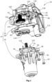
- the figure 1 12 shows an actuator 10 for driving an EGR valve for an internal combustion engine according to the present invention.
- the adjusting device 10 comprises a housing 14 which is formed from a first housing part 18 , a second housing part 22 and an intermediate housing element 26 .
- the intermediate housing element 26, which is made of plastic, is interposed with a seal 28, 29, which is in a groove 30, 34 (see figure 2 ) at a Flange surface 38, 46 is arranged on the first housing part 18 and the intermediate housing element 26, between the first housing part 18 and the second housing part 22 is arranged.
- the first housing part 18, the second housing part 22 and the intermediate housing element 26 have flange surfaces 38, 42, 46 in which openings 50, 54, 58 designed as holes are provided.
- a hole pattern formed by the holes 50, 54, 58 in each flange face 38, 42, 46 is uniform so that the holes 50, 54, 58 are aligned in an assembled condition.
- the housing parts 18, 22 and the intermediate housing element 26 can be screwed together using common screws 62.
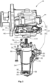
- FIG 2 a sectional view of the first housing part 18 is shown.
- An electric motor serving as a drive motor 66 is arranged in the first housing part 18 and has a fastening plate 70 on an axial end pointing towards the intermediate housing element 26, via which the electric motor 66 is screwed to a fastening flange section 74 of the first housing part 18 by means of fastening screws 78 in the axial direction. so that the electric motor 66 is mounted in the axial direction.
- the first housing part 18 additionally has a cylindrical recess 82 at a distal end thereof.
- An annular damping element 90 is applied to a cylinder jacket surface 86 of the cylindrical recess 82 .
- a cylindrical projection 94 formed by a bearing of the electric motor 66 is accommodated in the cylindrical depression 82 .
- the electric motor 66 is mounted radially and vibrations are dampened by the damping element 90 arranged between the depression 82 and the projection 94 .
- a corrugated spring 98 is arranged concentrically around the recess 82 in the first housing part 18 and is used to pretension the electric motor 66 in the axial direction when screwing it on.
- the electric motor 66 has electrical contact elements 102 which pass through recesses in the mounting plate 70 (see FIG figure 2 ). In order to energize the electric motor 66, the contact elements 102 are in an assembled state directly in contact with plug contacts 106 (see FIG figure 1 ), which are arranged in the intermediate housing element 26 and which are connected to the intermediate housing element 26 formed socket 110 via which an electrical voltage is supplied.
- the bushing 110 extends orthogonally to a plane formed by the intermediate housing member 26 .
- the electric motor 66 additionally has a drive pinion 114 which extends in the axial direction of the electric motor 66 in the direction of the second housing part 22 .
- the pinion gear 114 passes through an opening 118 in the intermediate housing member 26 so that the pinion gear 114 engages a gear box 122 (see FIG figure 1 ), which is arranged in the second housing part 22 engages.
- the transmission 122 includes a dual gear 126 and a spur gear (not shown) mechanically meshing with the dual gear 126 .
- An output shaft 130 of the eccentric element is arranged eccentrically to a shaft (not shown) of the spur gear via an eccentric element (not shown) which is fastened to the shaft of the spur gear.
- a bearing 134 is placed on the output shaft 130 and runs in a link 138 of a coupling element 142 to which an actuating member 146 in the form of a valve rod is attached.
- the described adjusting device according to the invention is thus simpler and more economical to produce, since the number of parts is kept small and assembly is simplified.
Landscapes
- Engineering & Computer Science (AREA)
- Chemical & Material Sciences (AREA)
- Combustion & Propulsion (AREA)
- Mechanical Engineering (AREA)
- General Engineering & Computer Science (AREA)
- Power Engineering (AREA)
- Electrically Driven Valve-Operating Means (AREA)
- Control Of Throttle Valves Provided In The Intake System Or In The Exhaust System (AREA)
Description
- Die vorliegende Erfindung betrifft eine Stellvorrichtung für eine Verbrennungskraftmaschine umfassend ein erstes Gehäuseteil, einen Antriebsmotor, welcher in dem ersten Gehäuseteil in einer axialen und einer radialen Richtung gelagert ist, ein Zwischengehäuseelement, über dass der Antriebsmotor elektrisch kontaktiert ist, und ein zweites Gehäuseteil, in dem ein Raum mit einer offenen Seite ausgebildet ist.
- Derartige Stellvorrichtungen dienen zum Antrieb unterschiedlicher Aggregate in einer Verbrennungskraftmaschine. Ein solches Aggregat kann beispielsweise eine Abgasklappe oder ein Ventil sein. Die Stellvorrichtung wird gewöhnlich an Orten eingesetzt, an denen Schmutz auftritt. Dadurch besteht die Gefahr, dass dieser Schmutz in die Stellvorrichtung eindringt und den Verschleiß innerhalb der Stellvorrichtung erhöht. Dies führt dazu, dass die Stellvorrichtung frühzeitig ausfällt. Um dies zu vermeiden ist es bekannt, das Gehäuse der Stellvorrichtung mit einer Dichtung zu versehen.
- Die
DE 10 2009 010 424 A1 offenbart einen Kfz-Aggregat-Elektromotor, welcher beispielsweise für eine Stellvorrichtung zum Stellen eines Abgasrückführungs-Ventils eingesetzt werden kann. Der Kfz-Aggregat-Elektromotor weist ein Motorgehäuse auf, an dem an einem zu einer Flanschfläche entgegengesetzten Ende eine Ausnehmung angeordnet ist, in der eine Ausstülpung eines Elektromotors aufgenommen und in radialer Richtung gelagert ist. An einem zur der Ausstülpung entgegengesetzten Seite des Elektromotors ist innerhalb des Motorgehäuses eine Abschlussplatte angeordnet mit der der Elektromotor zusammen an dem Motorgehäuse in axialer Richtung verschraubt ist und über die der Elektromotor elektrisch kontaktiert ist. Das derart fertig gestellt Kfz-Aggregat-Elektromotor ist beispielsweise an ein Stellergehäuse angeschraubt. - Aus der
US2009/0155101 A1 ist ein Scrollkompressor bekannt, an dessen zum Laufrad entgegengesetzten Ende ein Zwischengehäuseteil, welches Elektronikbauteile trägt, zwischen dem Motorgehäuse und einem die Elektronik verschließenden Deckel befestigt wird, indem der Deckel, das Motorgehäuse und das Zwischengehäuse ein gleiches Lochmuster aufweisen. - Zusätzlich ist aus der
DE 10 2013 101 938 A1 eine Stellvorrichtung für ein Ventil bekannt, dessen Ventilgehäuse gleichzeitig als Getriebegehäuseteil dient und durch ein Zwischengehäuseelement, welches ebenfalls den Getrieberaum begrenzt und den Elektromotor trägt, geschlossen wird. Hierzu weisen das Ventilgehäuse und das Zwischengehäuse ein gleiches Lochmuster auf. - Des Weiteren offenbart die
DE 10 2013 102 549 A1 ein Abgasrückführventil mit einem elektromotorischen Aktor. Das Gehäuse ist zweiteilig ausgebildet, wobei ein Gehäuseteil das Getriebe und das Ventil aufnimmt und das andere Gehäuseteil den Elektromotor aufnimmt. Die beiden Gehäuseteile werden über zueinander gewandte Flanschflächen aneinander mittels Schrauben befestigt. - Die
DE 20 2006 014 817 U1 offenbart eine Stellvorrichtung zur Sitzverstellung mit einem dreiteiligen Gehäuse, was aus einem Motorgehäuse, einen Getriebegehäuse und einen Getriebedeckel besteht, die aneinander befestigt sind. Der Stecker des Antriebsmotors ist an der zum Getriebegehäuse entgegengesetzten Seite angeordnet. - Ausgehend von dem Stand der Technik besteht ein stetiges Interesse daran, eine Stellvorrichtung bereitzustellen, welche wirtschaftlicher herstellbar ist. Die Wirtschaftlichkeit einer solchen Stellvorrichtung wird dabei von verschiedenen Faktoren beeinflusst, wie der Anzahl der Teile, der Komplexität der Teile und wie einfach die Teile zusammengebaut werden können.
- Die Aufgabe der vorliegenden Erfindung liegt somit darin, eine Stellvorrichtung für eine Verbrennungskraftmaschine zu schaffen, welche einfacher und wirtschaftlicher herstellbar ist.
- Diese Aufgabe wird durch eine Stellvorrichtung für eine Verbrennungskraftmaschine mit den Merkmalen des Anspruchs 1 gelöst.
- Bei der erfindungsgemäßen Stellvorrichtung weist das erste Gehäuseteil, das zweite Gehäuseteil und das Zwischengehäuseelement korrespondierende Öffnungen mit einem einheitlichen Lochmuster auf, wobei das erste Gehäuseteil mit dem zweiten Gehäuseteil unter Zwischenlage des Zwischengehäuseelementes miteinander verschraubt sind, wobei das Zwischengehäuseelement den Raum des zweiten Gehäuseteils, in dem ein Getriebe der Stellvorrichtung angeordnet ist, zu der offenen Seite begrenzt. Eine Bestromung des Antriebsmotors kann somit direkt über das Zwischengehäuseelement erfolgen. Zusätzliche Herstellungskosten und Lagerkosten für zusätzliche Teile können dadurch eingespart werden, so dass die Stellvorrichtung wirtschaftlicher hergestellt werden kann. Unter einem einheitlichen Lochmuster im Sinne der Erfindung ist eine gleiche Anordnung der Löcher zu verstehen, so dass die Löcher nach einem Zusammenbau der Gehäuseteile in Überdeckung gebracht werden. Über das einheitliche Lochmuster, können alle drei Gehäuseteile somit auf einmal miteinander verschraubt werden, so dass der Zusammenbau vereinfacht wird. Dadurch ist die Stellvorrichtung einfacher und wirtschaftlicher herstellbar. Über das Getriebe ist es möglich, ein Drehmoment des Antriebsmotors in eine Stellbewegung des Betätigungsorgans zu transformieren. Als Getriebe wird dabei vorzugsweise ein Stirnradgetriebe verwendet.
- In einer bevorzugten Ausführung der Erfindung weist der Antriebsmotor an einem proximalen axialen Ende eine Befestigungsplatte auf, über welche der Antriebsmotor an einem Befestigungsflanschabschnitt des ersten Gehäuseteils, welcher im Inneren des ersten Gehäuseteils ausgebildet ist, in axialer Richtung verschraubt ist. Dadurch wird der Antriebsmotor in axialer Richtung im ersten Gehäuseteil fixiert.
- In einer weiteren bevorzugten Ausführung der Erfindung weist der Antriebsmotor an einem distalen axialen Ende einen durch ein Lager des Antriebsmotors gebildeten Vorsprung auf, der in einer Vertiefung des ersten Gehäuseteils aufgenommen und radial gehalten ist. Der Antriebsmotor kann dadurch auf einfache Weise in seiner radialen Beweglichkeit eingeschränkt werden.
- Zwischen dem Vorsprung des Antriebsmotors und der Vertiefung ist vorzugsweise ein Dämpfungselement angeordnet. Der Vorsprung des Antriebsmotors liegt somit nicht direkt an der Vertiefung an, so dass ein aneinander schlagen des Vorsprungs und der Vertiefung vermieden wird. Die radialen Bewegungen werden zudem durch das Dämpfungselement aufgenommen und gedämpft, Als Dämpfungselement wird dabei vorzugsweise ein elastisches ringförmiges Bauteil verwendet.
- Vorteilhaft ist es, wenn im ersten Gehäuseteil, um die Vertiefung, eine Wellfeder angeordnet ist, welche in einer axialen Richtung des Antriebsmotors vorgespannt ist. In einem zusammengebauten Zustand drückt die Wellfeder den Antriebsmotor somit in Richtung des zweiten Gehäuseteils. Dadurch wird der Antriebsmotor in dem Gehäuse verspannt, so dass Relativschwingungen zwischen dem ersten Gehäuseteil und dem Antriebsmotor weiter reduziert werden.
- In einer bevorzugten Ausgestaltung ist das erste Gehäuseteil einteilig ausgebildet. Das erste Gehäuseteil wird somit aus einem Stück gefertigt, so dass die Teilezahl der Stellvorrichtung reduziert und die Stellvorrichtung wirtschaftlicher herstellbar ist. Zudem wird durch ein einteiliges Gehäuseteil die Steifigkeit des Gehäuses erhöht, so dass Schwingungen besser aufgenommen werden können.
- In einer bevorzugten Weiterbildung der Erfindung ist das erste Gehäuseteil aus Aluminium gebildet. Aluminium hat den Vorteil, dass dieses Material eine hohe Wärmeleitfähigkeit bei einer guten Steifigkeit des aus diesem Material hergestellten ersten Gehäuseteils hat. Dadurch kann ein Gehäuse gebildet werden, welches sehr gut die Wärme des Antriebsmotors abführt und trotzdem eine gute Schwingungsaufnahme hat. Da Aluminium im Verhältnis zu seiner Festigkeit ein relativ leichtes Material ist, kann zudem das Gewicht der Stellvorrichtung reduziert werden.
- In einer bevorzugten Ausführung der Erfindung ist am Zwischengehäuseelement eine Buchse für einen Stecker ausgebildet. Über diese Buchse, welche außerhalb des durch das erste Gehäuseteil, das zweite Gehäuseteil und das Zwischengehäuseelement begrenzten Raums angeordnet ist, können das Zwischengehäuseelement und damit der Antriebsmotor bestromt werden. Die Buchse kann dabei vorzugsweise in verschiedenen Richtungen ausgerichtet sein, um den verschiedenen Einbaugegebenheiten Rechnung zu tragen, ohne dass die Form des ersten oder zweiten Gehäuseteils geändert werden müsste.
- Besonders vorteilhaft ist es, wenn das Zwischengehäuseelement aus Kunststoff gebildet ist. Die Herstellung des Gehäuses aus Kunststoff führt zu geringeren Materialkosten, wodurch die Stellvorrichtung wirtschaftlicher herstellbar ist. Darüber hinaus hat Kunststoff ein geringeres Gewicht als Metall, so dass auch das Gewicht der Stellvorrichtung reduziert wird. Vorzugsweise kann als Kunststoff auch ein faserverstärkter Kunststoff Verwendung finden, um eine noch höhere Festigkeit des Zwischengehäuseelementes zu erreichen. Zudem kann über ein solches Zwischengehäuseelement aus Kunststoff eine schwingungsdämpfende Wirkung erzielt werden, insbesondere zwischen zwei festen Metallgehäusen.
- Vorteilhafterweise ragt ein Antriebsritzel des Antriebsmotors durch das Zwischengehäuseelement in das zweite Gehäuseteil. Das Zwischengehäuseelement weist somit eine Öffnung für das Antriebsritzel auf. Dadurch ist es trotz erfindungsgemäßer Anordnung des Zwischengehäuseelementes möglich, ein in das zweite Gehäuseteil ragendes Betätigungsorgan anzutreiben.
- In einer bevorzugten Ausgestaltung der Erfindung weisen das erste und zweite Gehäuseteil jeweils eine Flanschfläche, in der die korrespondierenden Öffnungen angeordnet sind, auf, welche unter Zwischenlage einer Dichtung an einer zu dem jeweiligen Gehäuseteil weisenden Fläche des Zwischengehäuseelementes anliegt. Die Dichtung liegt dabei radial innenliegend zu den Öffnungen an der Flanschfläche an. Dadurch wird eine dichtende Verbindung zwischen den drei Gehäuseteilen sichergestellt.
- Vorteilhaft ist es, wenn die Dichtung in einer Nut des jeweiligen Gehäuseteils und des Zwischengehäuseelementes, welche auf den gegenüberliegenden Flanschflächen ausgebildet ist, angeordnet ist. Die Dichtung hat dabei eine axiale Abmessung, welche größer als die Tiefe der Nut ist, so dass die Dichtung die Nut überragt. Dadurch wird die Dichtung in einer Position fixiert, so dass dauerhaft eine dichtende Verbindung gewährleistet werden kann.
- In einer weiteren bevorzugten Ausführung ist der Antriebsmotor ein Elektromotor, da dieser eine hohe Stellgenauigkeit sicherstellt.
- Es wird somit eine Stellvorrichtung für eine Verbrennungskraftmaschine geschaffen, welche einfacher und wirtschaftlicher herstellbar ist, indem die Montage vereinfacht wird. Zusätzlich wird die Lebensdauer erhöht, da die Räume gegeneinander weitestgehend abgedichtet sind und Schwingungen innerhalb der Stellvorrichtung vermieden werden.
- Weitere Einzelheiten und Vorteile der vorliegenden Erfindung ergeben sich aus der nachfolgenden Beschreibung des Ausführungsbeispiels in Verbindung mit den Zeichnungen. In diesen zeigen:
-
Figur 1 : Explosionszeichnung der erfindungsgemäßen Stellvorrichtung für eine Verbrennungskraftmaschine, und -
Figur 2 : Weitere Explosionszeichnung der erfindungsgemäßen Stellvorrichtung nachFigur 1 . - Die
Figur 1 zeigt eine Stellvorrichtung 10 zum Antrieb eines AGR-Ventils für eine Verbrennungskraftmaschine nach der vorliegenden Erfindung. Die Stellvorrichtung 10 umfasst ein Gehäuse 14, welches aus einem ersten Gehäuseteil 18, einem zweiten Gehäuseteil 22 und einem Zwischengehäuseelement 26 gebildet ist. Das Zwischengehäuseelement 26, welches aus Kunststoff gebildet ist, ist dabei unter Zwischenlage einer Dichtung 28, 29, welche in einer Nut 30, 34 (sieheFigur 2 ) an einer Flanschfläche 38, 46 am ersten Gehäuseteil 18 und dem Zwischengehäuseelement 26 angeordnet ist, zwischen dem ersten Gehäuseteil 18 und dem zweiten Gehäuseteil 22 angeordnet. Das erste Gehäuseteil 18, das zweite Gehäuseteil 22 und das Zwischengehäuseelement 26 weisen Flanschflächen 38, 42, 46, in denen als Löcher ausgebildete Öffnungen 50, 54, 58 vorgesehen sind, auf. Ein durch die Löcher 50, 54, 58 in jeder Flanschfläche 38, 42, 46 gebildetes Lochmuster ist dabei einheitlich, so dass die Löcher 50, 54, 58 in einem zusammengebauten Zustand fluchten. Dadurch können die Gehäuseteile 18, 22 und das Zwischengehäuseelement 26 über gemeinsame Schrauben 62 miteinander verschraubt werden. - In
Figur 2 ist eine Schnittdarstellung des ersten Gehäuseteils 18 gezeigt. In dem ersten Gehäuseteil 18 ist ein als Antriebsmotor 66 dienender Elektromotor angeordnet, der an einem zum Zwischengehäuseelement 26 weisenden axialen Ende eine Befestigungsplatte 70 aufweist, über die der Elektromotor 66 an einem Befestigungsflanschabschnitt 74 des ersten Gehäuseteils 18 mittels Befestigungsschrauben 78 in axialer Richtung verschraubt ist, so dass der Elektromotor 66 in axialer Richtung gelagert ist. Das erste Gehäuseteil 18 weist zusätzlich an einem distalen Ende davon eine zylindrische Vertiefung 82 auf. Auf eine Zylindermantelfläche 86 der zylindrischen Vertiefung 82 ist ein ringförmiges Dämpfungselement 90 aufgebracht. In der zylindrischen Vertiefung 82 ist ein durch ein Lager des Elektromotors 66 gebildeter zylindrischer Vorsprung 94 aufgenommen. Dadurch ist der Elektromotor 66 radial gelagert und Schwingungen werden durch das zwischen Vertiefung 82 und Vorsprung 94 angeordnete Dämpfungselement 90 gedämpft. - Um die Vertiefung 82 in dem ersten Gehäuseteil 18 ist konzentrisch eine Wellfeder 98 angeordnet, über die der Elektromotor 66 in axialer Richtung beim Verschrauben vorgespannt wird.
- Der Elektromotor 66 weist elektrische Kontaktelemente 102 auf, welche durch Aussparungen in der Befestigungsplatte 70 hindurchtreten (siehe
Figur 2 ). Zum Bestromen des Elektromotors 66 sind die Kontaktelemente 102 in einem zusammengebauten Zustand direkt in Kontakt mit Steckkontakten 106 (sieheFigur 1 ), welche in dem Zwischengehäuseelement 26 angeordnet sind und welche an dem Zwischengehäuseelement 26 ausgebildeten Buchse 110 verbunden sind über welche eine elektrische Spannungsversorgung erfolgt. Die Buchse 110 erstreckt sich orthogonal zu einer durch das Zwischengehäuseelement 26 ausgebildeten Ebene. - Der Elektromotor 66 weist zusätzlich ein Antriebsritzel 114 auf, welches sich in der axialen Richtung des Elektromotors 66 in Richtung des zweiten Gehäuseteils 22 erstreckt. In einem zusammengebauten Zustand tritt das Antriebsritzel 114 durch eine Öffnung 118 in dem Zwischengehäuseelement 26, so dass das Antriebsritzel 114 in ein Getriebe 122 (siehe
Figur 1 ), welches in dem zweiten Gehäuseteil 22 angeordnet ist, eingreift. Das Getriebe 122 umfasst ein Doppelzahnrad 126 und ein Stirnrad (nicht gezeigt), welches mechanisch mit dem Doppelzahnrad 126 im Eingriff ist. Exzentrisch zu einer Welle (nicht gezeigt) des Stirnrades ist über ein Exzenterelement (nicht gezeigt), welches auf der Welle des Stirnrades befestigt ist, eine Ausgangswelle 130 des Exzenterelementes angeordnet. Auf der Ausgangswelle 130 ist ein Lager 134 platziert, welches in einer Kulisse 138 eines Kopplungselementes 142 läuft, an dem ein Betätigungsorgan 146 in Form einer Ventilstange befestigt ist. - Die beschriebene erfindungsgemäße Stellvorrichtung ist somit einfacher und wirtschaftlicher herstellbar, da die Teileanzahl gering gehalten wird und der Zusammenbau vereinfacht ist.
- Es sollte deutlich sein, dass der Schutzbereich nicht auf das beschriebene Ausführungsbeispiel einer Stellvorrichtung beschränkt ist, sondern verschiedene Modifikationen und konstruktive Änderungen denkbar sind. Beispielsweise sind Ausgestaltungen denkbar, bei welchen die Buchse in einem anderen Winkel zu der Ebene des Zwischengehäuseelementes ausgerichtet ist.
-
- 10
- Stellvorrichtung
- 14
- Gehäuse
- 18
- erstes Gehäuseteil
- 22
- zweites Gehäuseteil
- 26
- Zwischengehäuseelement
- 28
- Dichtung
- 29
- Dichtung
- 30
- Nut
- 34
- Nut
- 38
- Flanschfläche
- 42
- Flanschfläche
- 46
- Flanschfläche
- 50
- Öffnung
- 54
- Öffnung
- 58
- Öffnung
- 62
- Schraube
- 66
- Antriebsmotor
- 70
- Befestigungsplatte
- 74
- Befestigungsflanschabschnitt
- 78
- Befestigungsschraube
- 82
- Vertiefung
- 86
- Zylindermantelfläche
- 90
- Dämpfungselement
- 94
- Vorsprung
- 98
- Wellfeder
- 102
- Kontaktelement
- 106
- Steckkontakt
- 110
- Buchse
- 114
- Antriebsritzel
- 118
- Öffnung
- 122
- Getriebe
- 126
- Doppelzahnrad
- 130
- Ausgangswelle
- 134
- Lager
- 138
- Kulisse
- 142
- Kopplungselement
- 146
- Betätigungsorgan
Claims (13)
- Stellvorrichtung (10) für eine Verbrennungskraftmaschine umfassend:- ein erstes Gehäuseteil (18),- einen Antriebsmotor (66), welcher in dem ersten Gehäuseteil (18) in einer axialen und einer radialen Richtung gelagert ist,- ein Zwischengehäuseelement (26),
und- ein zweites Gehäuseteil (22), in dem ein Raum mit einer offenen Seite ausgebildet ist, wobei, das erste Gehäuseteil (18), das zweite Gehäuseteil (22) und das Zwischengehäuseelement (26) korrespondierende Öffnungen (50, 54, 58) mit einem einheitlichen Lochmuster aufweisen und das erste Gehäuseteil (18) mit dem zweiten Gehäuseteil (22) unter Zwischenlage des Zwischengehäuseelementes (26) miteinander verschraubt sind, dadurch gekennzeichnet, dass der Antriebsmotor (66) über das Zwischengehäuseelement (26) elektrisch kontaktiert ist, und dass das Zwischengehäuseelement (26) den Raum des zweiten Gehäuseteils (22), in dem ein Getriebe (122) der Stellvorrichtung (10) angeordnet ist, zu der offenen Seite begrenzt. - Stellvorrichtung (10) nach Anspruch 1, dadurch gekennzeichnet, dass der Antriebsmotor (66) an einem proximalen axialen Ende eine Befestigungsplatte (70) aufweist, über welche der Antriebsmotor (66) an einem Befestigungsflanschabschnitt (74) des ersten Gehäuseteils (18), welcher im Inneren des ersten Gehäuseteils (18) ausgebildet ist, in axialer Richtung verschraubt ist.
- Stellvorrichtung (10) nach Anspruch 1 oder 2, dadurch gekennzeichnet, dass der Antriebsmotor (66) an einem distalen axialen Ende einen durch ein Lager des Antriebsmotors (66) gebildeten Vorsprung (94) aufweist, der in einer Vertiefung (82) des ersten Gehäuseteils (18) aufgenommen und radial gehalten ist.
- Stellvorrichtung (10) nach Anspruch 3, dadurch gekennzeichnet, dass zwischen dem Vorsprung (94) des Antriebsmotors (66) und der Vertiefung (82) ein Dämpfungselement (90) angeordnet ist.
- Stellvorrichtung (10) nach Anspruch 3 oder 4, dadurch gekennzeichnet, dass im ersten Gehäuseteil (18), um die Vertiefung (82), eine Wellfeder (98) angeordnet ist, welche in einer axialen Richtung des Antriebsmotors (66) vorgespannt ist.
- Stellvorrichtung (10) nach einem der vorherigen Ansprüche, dadurch gekennzeichnet, dass das erste Gehäuseteil (18) einteilig ausgebildet ist.
- Stellvorrichtung (10) nach einem der vorherigen Ansprüche, dadurch gekennzeichnet, dass das erste Gehäuseteil (18) aus Aluminium gebildet ist.
- Stellvorrichtung (10) nach einem der vorherigen Ansprüche, dadurch gekennzeichnet, dass am Zwischengehäuseelement (26) eine Buchse (110) für einen Stecker ausgebildet ist.
- Stellvorrichtung (10) nach einem der vorherigen Ansprüche, dadurch gekennzeichnet, dass das Zwischengehäuseelement (26) aus Kunststoff gebildet ist.
- Stellvorrichtung (10) nach einem der vorherigen Ansprüche, dadurch gekennzeichnet, dass ein Antriebsritzel (114) des Antriebsmotors (66) durch das Zwischengehäuseelement (26) in das zweite Gehäuseteil (22) ragt.
- Stellvorrichtung (10) nach einem der vorherigen Ansprüche, dadurch gekennzeichnet, dass das erste und zweite Gehäuseteil (18, 22) jeweils eine Flanschfläche (38, 42), in der die korrespondierenden Öffnungen (50, 54, 58) angeordnet sind, aufweisen, welche unter Zwischenlage einer Dichtung (28, 29) an einer zu dem jeweiligen Gehäuseteil (18, 22) weisenden Fläche des Zwischengehäuseelementes (26) anliegt.
- Stellvorrichtung (10) nach einem der vorherigen Ansprüche, dadurch gekennzeichnet, dass die Dichtung (28, 29) in einer Nut (30, 34) des jeweiligen Gehäuseteils (18, 22) und des Zwischengehäuseelementes (26), welche auf den gegenüberliegenden Flanschflächen (38, 46) ausgebildet ist, angeordnet ist.
- Stellvorrichtung (10) nach einem der vorherigen Ansprüche, dadurch gekennzeichnet, dass der Antriebsmotor (66) ein Elektromotor ist.
Applications Claiming Priority (2)
| Application Number | Priority Date | Filing Date | Title |
|---|---|---|---|
| DE102017110489.5A DE102017110489A1 (de) | 2017-05-15 | 2017-05-15 | Stellvorrichtung für eine Verbrennungskraftmaschine |
| PCT/EP2018/062183 WO2018210689A1 (de) | 2017-05-15 | 2018-05-11 | Stellvorrichtung für eine verbrennungskraftmaschine |
Publications (2)
| Publication Number | Publication Date |
|---|---|
| EP3625878A1 EP3625878A1 (de) | 2020-03-25 |
| EP3625878B1 true EP3625878B1 (de) | 2023-04-05 |
Family
ID=62167313
Family Applications (1)
| Application Number | Title | Priority Date | Filing Date |
|---|---|---|---|
| EP18724835.6A Active EP3625878B1 (de) | 2017-05-15 | 2018-05-11 | Stellvorrichtung für eine verbrennungskraftmaschine |
Country Status (4)
| Country | Link |
|---|---|
| EP (1) | EP3625878B1 (de) |
| CN (1) | CN110651414B (de) |
| DE (1) | DE102017110489A1 (de) |
| WO (1) | WO2018210689A1 (de) |
Families Citing this family (1)
| Publication number | Priority date | Publication date | Assignee | Title |
|---|---|---|---|---|
| DE102020216462A1 (de) * | 2020-12-22 | 2022-06-23 | Mahle International Gmbh | Antriebsaggregat |
Citations (1)
| Publication number | Priority date | Publication date | Assignee | Title |
|---|---|---|---|---|
| DE102013101938A1 (de) * | 2013-02-27 | 2014-08-28 | Pierburg Gmbh | Antriebsanordnung für ein Aggregat eines Verbrennungsmotors und Abgasrückführventil |
Family Cites Families (11)
| Publication number | Priority date | Publication date | Assignee | Title |
|---|---|---|---|---|
| DE10341394A1 (de) * | 2003-09-05 | 2005-04-28 | Pierburg Gmbh | Stellvorrichtung |
| DE202006014817U1 (de) * | 2006-03-07 | 2006-12-14 | Keiper Gmbh & Co.Kg | Motorischer Stellantrieb für einen Fahrzeugsitz |
| JP5109642B2 (ja) * | 2007-12-18 | 2012-12-26 | 株式会社豊田自動織機 | 電動圧縮機 |
| DE102008053570B4 (de) * | 2008-10-15 | 2010-07-08 | Bühler Motor GmbH | Stellantrieb, insbesondere zur Betätigung eines Abgasrückführventils |
| DE102009010424A1 (de) * | 2009-02-26 | 2010-09-02 | Pierburg Gmbh | Kfz-Aggregat-Elektromotor |
| US20130154402A1 (en) * | 2010-05-28 | 2013-06-20 | Kiekert Ag | Actuating drive for a motor vehicle |
| JP2013104391A (ja) * | 2011-11-15 | 2013-05-30 | Aisan Industry Co Ltd | スロットル装置 |
| DE102012108853A1 (de) * | 2012-09-20 | 2014-03-20 | Hella Kgaa Hueck & Co. | Stellantrieb |
| DE102013102549B4 (de) * | 2013-03-13 | 2022-07-14 | Pierburg Gmbh | Abgasventilvorrichtung für eine Verbrennungskraftmaschine |
| DE102013107111A1 (de) * | 2013-07-05 | 2015-01-08 | Pierburg Gmbh | Aktor zum Antrieb einer Ventileinheit einer Verbrennungskraftmaschine |
| DE102014114964B4 (de) * | 2014-10-15 | 2016-05-25 | Pierburg Gmbh | Regelbare, mechanisch angetriebene Kühlmittelpumpe für eine Verbrennungskraftmaschine |
-
2017
- 2017-05-15 DE DE102017110489.5A patent/DE102017110489A1/de not_active Withdrawn
-
2018
- 2018-05-11 WO PCT/EP2018/062183 patent/WO2018210689A1/de not_active Ceased
- 2018-05-11 CN CN201880032269.4A patent/CN110651414B/zh active Active
- 2018-05-11 EP EP18724835.6A patent/EP3625878B1/de active Active
Patent Citations (1)
| Publication number | Priority date | Publication date | Assignee | Title |
|---|---|---|---|---|
| DE102013101938A1 (de) * | 2013-02-27 | 2014-08-28 | Pierburg Gmbh | Antriebsanordnung für ein Aggregat eines Verbrennungsmotors und Abgasrückführventil |
Also Published As
| Publication number | Publication date |
|---|---|
| CN110651414B (zh) | 2022-02-01 |
| EP3625878A1 (de) | 2020-03-25 |
| CN110651414A (zh) | 2020-01-03 |
| DE102017110489A1 (de) | 2018-11-15 |
| WO2018210689A1 (de) | 2018-11-22 |
Similar Documents
| Publication | Publication Date | Title |
|---|---|---|
| DE69425705T3 (de) | Positionssensoren | |
| DE102016000023A1 (de) | Kraftfahrzeug-Reduziereinrichtung | |
| DE102019207848B4 (de) | Motor und Ventilantriebsvorrichtung | |
| EP3129635B1 (de) | Klappenvorrichtung für eine verbrennungskraftmaschine | |
| DE102007051475A1 (de) | Verbindung eines Achsversatzausgleichselements und eines Innenrings eines Wälzlagers | |
| EP3017175B1 (de) | Aktor zum antrieb einer ventileinheit einer verbrennungskraftmaschine | |
| DE102018103221A1 (de) | Wellgetriebe und Verfahren zur Montage eines Wellgetriebes | |
| DE102013109997A1 (de) | Aktuator | |
| DE102010063058B4 (de) | Verbindungsvorrichtung für einen Heckklappenantrieb eines Fahrzeugs | |
| EP3227540B1 (de) | Klappenvorrichtung für eine verbrennungskraftmaschine | |
| EP3625878B1 (de) | Stellvorrichtung für eine verbrennungskraftmaschine | |
| DE10341396B3 (de) | Klappenstellvorrichtung | |
| DE3148872A1 (de) | Fluessigkeitsreibungskupplung mit temperatursteuerung | |
| WO2013010736A1 (de) | Statorbaueinheit sowie nockenwellenverstellvorrichtung mit statorbaueinheit | |
| EP3227541B1 (de) | Klappenvorrichtung für eine verbrennungskraftmaschine | |
| EP3431735A1 (de) | Klappenvorrichtung | |
| DE102014007568A1 (de) | Befestigungsanordnung eines Statorelements einer elektrischen Maschine an einem Bauelement, insbesondere für einen Kraftwagen | |
| DE102014210361B4 (de) | Nockenwellenversteller mit einem Stellmotor und einem Verstellgetriebe | |
| DE102018107108A1 (de) | Umschaltventil zum Steuern eines Hydraulikflüssigkeitsstroms und Pleuel für eine Brennkraftmaschine mit variabler Verdichtung mit einem Umschaltventil | |
| DE102017208657A1 (de) | Überlastungsschutz eines Schneckengetriebes inkl. Anfederung der Schneckenwelle | |
| WO2017194046A1 (de) | Stellantrieb | |
| WO2008028782A1 (de) | Spannvorrichtung eines zugmitteltriebs | |
| DE10156478B4 (de) | Drosselklappenstelleinheit | |
| DE102018107058A1 (de) | Stellvorrichtung | |
| DE102019123611A1 (de) | Wellgetriebe |
Legal Events
| Date | Code | Title | Description |
|---|---|---|---|
| STAA | Information on the status of an ep patent application or granted ep patent |
Free format text: STATUS: UNKNOWN |
|
| STAA | Information on the status of an ep patent application or granted ep patent |
Free format text: STATUS: THE INTERNATIONAL PUBLICATION HAS BEEN MADE |
|
| PUAI | Public reference made under article 153(3) epc to a published international application that has entered the european phase |
Free format text: ORIGINAL CODE: 0009012 |
|
| STAA | Information on the status of an ep patent application or granted ep patent |
Free format text: STATUS: REQUEST FOR EXAMINATION WAS MADE |
|
| 17P | Request for examination filed |
Effective date: 20191203 |
|
| AK | Designated contracting states |
Kind code of ref document: A1 Designated state(s): AL AT BE BG CH CY CZ DE DK EE ES FI FR GB GR HR HU IE IS IT LI LT LU LV MC MK MT NL NO PL PT RO RS SE SI SK SM TR |
|
| AX | Request for extension of the european patent |
Extension state: BA ME |
|
| DAV | Request for validation of the european patent (deleted) | ||
| DAX | Request for extension of the european patent (deleted) | ||
| STAA | Information on the status of an ep patent application or granted ep patent |
Free format text: STATUS: EXAMINATION IS IN PROGRESS |
|
| 17Q | First examination report despatched |
Effective date: 20210429 |
|
| REG | Reference to a national code |
Ref country code: DE Ref legal event code: R079 Ref document number: 502018011903 Country of ref document: DE Free format text: PREVIOUS MAIN CLASS: H02K0005220000 Ipc: H02K0005040000 |
|
| GRAP | Despatch of communication of intention to grant a patent |
Free format text: ORIGINAL CODE: EPIDOSNIGR1 |
|
| STAA | Information on the status of an ep patent application or granted ep patent |
Free format text: STATUS: GRANT OF PATENT IS INTENDED |
|
| RIC1 | Information provided on ipc code assigned before grant |
Ipc: F02M 26/72 20160101ALI20221011BHEP Ipc: F02M 26/66 20160101ALI20221011BHEP Ipc: F02M 26/54 20160101ALI20221011BHEP Ipc: H02K 7/116 20060101ALI20221011BHEP Ipc: H02K 5/22 20060101ALI20221011BHEP Ipc: H02K 5/04 20060101AFI20221011BHEP |
|
| INTG | Intention to grant announced |
Effective date: 20221028 |
|
| RIN1 | Information on inventor provided before grant (corrected) |
Inventor name: SARI, OSMAN Inventor name: TURAN, ALPER Inventor name: WAGNER, MICHAEL |
|
| GRAS | Grant fee paid |
Free format text: ORIGINAL CODE: EPIDOSNIGR3 |
|
| GRAA | (expected) grant |
Free format text: ORIGINAL CODE: 0009210 |
|
| STAA | Information on the status of an ep patent application or granted ep patent |
Free format text: STATUS: THE PATENT HAS BEEN GRANTED |
|
| AK | Designated contracting states |
Kind code of ref document: B1 Designated state(s): AL AT BE BG CH CY CZ DE DK EE ES FI FR GB GR HR HU IE IS IT LI LT LU LV MC MK MT NL NO PL PT RO RS SE SI SK SM TR |
|
| REG | Reference to a national code |
Ref country code: GB Ref legal event code: FG4D Free format text: NOT ENGLISH |
|
| REG | Reference to a national code |
Ref country code: DE Ref legal event code: R096 Ref document number: 502018011903 Country of ref document: DE |
|
| REG | Reference to a national code |
Ref country code: CH Ref legal event code: EP |
|
| REG | Reference to a national code |
Ref country code: AT Ref legal event code: REF Ref document number: 1558999 Country of ref document: AT Kind code of ref document: T Effective date: 20230415 |
|
| REG | Reference to a national code |
Ref country code: IE Ref legal event code: FG4D Free format text: LANGUAGE OF EP DOCUMENT: GERMAN |
|
| REG | Reference to a national code |
Ref country code: LT Ref legal event code: MG9D |
|
| REG | Reference to a national code |
Ref country code: NL Ref legal event code: MP Effective date: 20230405 |
|
| PG25 | Lapsed in a contracting state [announced via postgrant information from national office to epo] |
Ref country code: NL Free format text: LAPSE BECAUSE OF FAILURE TO SUBMIT A TRANSLATION OF THE DESCRIPTION OR TO PAY THE FEE WITHIN THE PRESCRIBED TIME-LIMIT Effective date: 20230405 |
|
| PG25 | Lapsed in a contracting state [announced via postgrant information from national office to epo] |
Ref country code: SE Free format text: LAPSE BECAUSE OF FAILURE TO SUBMIT A TRANSLATION OF THE DESCRIPTION OR TO PAY THE FEE WITHIN THE PRESCRIBED TIME-LIMIT Effective date: 20230405 Ref country code: PT Free format text: LAPSE BECAUSE OF FAILURE TO SUBMIT A TRANSLATION OF THE DESCRIPTION OR TO PAY THE FEE WITHIN THE PRESCRIBED TIME-LIMIT Effective date: 20230807 Ref country code: NO Free format text: LAPSE BECAUSE OF FAILURE TO SUBMIT A TRANSLATION OF THE DESCRIPTION OR TO PAY THE FEE WITHIN THE PRESCRIBED TIME-LIMIT Effective date: 20230705 Ref country code: ES Free format text: LAPSE BECAUSE OF FAILURE TO SUBMIT A TRANSLATION OF THE DESCRIPTION OR TO PAY THE FEE WITHIN THE PRESCRIBED TIME-LIMIT Effective date: 20230405 |
|
| PG25 | Lapsed in a contracting state [announced via postgrant information from national office to epo] |
Ref country code: RS Free format text: LAPSE BECAUSE OF FAILURE TO SUBMIT A TRANSLATION OF THE DESCRIPTION OR TO PAY THE FEE WITHIN THE PRESCRIBED TIME-LIMIT Effective date: 20230405 Ref country code: PL Free format text: LAPSE BECAUSE OF FAILURE TO SUBMIT A TRANSLATION OF THE DESCRIPTION OR TO PAY THE FEE WITHIN THE PRESCRIBED TIME-LIMIT Effective date: 20230405 Ref country code: LV Free format text: LAPSE BECAUSE OF FAILURE TO SUBMIT A TRANSLATION OF THE DESCRIPTION OR TO PAY THE FEE WITHIN THE PRESCRIBED TIME-LIMIT Effective date: 20230405 Ref country code: LT Free format text: LAPSE BECAUSE OF FAILURE TO SUBMIT A TRANSLATION OF THE DESCRIPTION OR TO PAY THE FEE WITHIN THE PRESCRIBED TIME-LIMIT Effective date: 20230405 Ref country code: IS Free format text: LAPSE BECAUSE OF FAILURE TO SUBMIT A TRANSLATION OF THE DESCRIPTION OR TO PAY THE FEE WITHIN THE PRESCRIBED TIME-LIMIT Effective date: 20230805 Ref country code: HR Free format text: LAPSE BECAUSE OF FAILURE TO SUBMIT A TRANSLATION OF THE DESCRIPTION OR TO PAY THE FEE WITHIN THE PRESCRIBED TIME-LIMIT Effective date: 20230405 Ref country code: GR Free format text: LAPSE BECAUSE OF FAILURE TO SUBMIT A TRANSLATION OF THE DESCRIPTION OR TO PAY THE FEE WITHIN THE PRESCRIBED TIME-LIMIT Effective date: 20230706 Ref country code: AL Free format text: LAPSE BECAUSE OF FAILURE TO SUBMIT A TRANSLATION OF THE DESCRIPTION OR TO PAY THE FEE WITHIN THE PRESCRIBED TIME-LIMIT Effective date: 20230405 |
|
| PG25 | Lapsed in a contracting state [announced via postgrant information from national office to epo] |
Ref country code: FI Free format text: LAPSE BECAUSE OF FAILURE TO SUBMIT A TRANSLATION OF THE DESCRIPTION OR TO PAY THE FEE WITHIN THE PRESCRIBED TIME-LIMIT Effective date: 20230405 |
|
| REG | Reference to a national code |
Ref country code: CH Ref legal event code: PL |
|
| REG | Reference to a national code |
Ref country code: DE Ref legal event code: R097 Ref document number: 502018011903 Country of ref document: DE |
|
| PG25 | Lapsed in a contracting state [announced via postgrant information from national office to epo] |
Ref country code: SK Free format text: LAPSE BECAUSE OF FAILURE TO SUBMIT A TRANSLATION OF THE DESCRIPTION OR TO PAY THE FEE WITHIN THE PRESCRIBED TIME-LIMIT Effective date: 20230405 |
|
| PG25 | Lapsed in a contracting state [announced via postgrant information from national office to epo] |
Ref country code: MC Free format text: LAPSE BECAUSE OF FAILURE TO SUBMIT A TRANSLATION OF THE DESCRIPTION OR TO PAY THE FEE WITHIN THE PRESCRIBED TIME-LIMIT Effective date: 20230405 |
|
| REG | Reference to a national code |
Ref country code: BE Ref legal event code: MM Effective date: 20230531 |
|
| PG25 | Lapsed in a contracting state [announced via postgrant information from national office to epo] |
Ref country code: SM Free format text: LAPSE BECAUSE OF FAILURE TO SUBMIT A TRANSLATION OF THE DESCRIPTION OR TO PAY THE FEE WITHIN THE PRESCRIBED TIME-LIMIT Effective date: 20230405 Ref country code: SK Free format text: LAPSE BECAUSE OF FAILURE TO SUBMIT A TRANSLATION OF THE DESCRIPTION OR TO PAY THE FEE WITHIN THE PRESCRIBED TIME-LIMIT Effective date: 20230405 Ref country code: RO Free format text: LAPSE BECAUSE OF FAILURE TO SUBMIT A TRANSLATION OF THE DESCRIPTION OR TO PAY THE FEE WITHIN THE PRESCRIBED TIME-LIMIT Effective date: 20230405 Ref country code: MC Free format text: LAPSE BECAUSE OF FAILURE TO SUBMIT A TRANSLATION OF THE DESCRIPTION OR TO PAY THE FEE WITHIN THE PRESCRIBED TIME-LIMIT Effective date: 20230405 Ref country code: LU Free format text: LAPSE BECAUSE OF NON-PAYMENT OF DUE FEES Effective date: 20230511 Ref country code: LI Free format text: LAPSE BECAUSE OF NON-PAYMENT OF DUE FEES Effective date: 20230531 Ref country code: EE Free format text: LAPSE BECAUSE OF FAILURE TO SUBMIT A TRANSLATION OF THE DESCRIPTION OR TO PAY THE FEE WITHIN THE PRESCRIBED TIME-LIMIT Effective date: 20230405 Ref country code: DK Free format text: LAPSE BECAUSE OF FAILURE TO SUBMIT A TRANSLATION OF THE DESCRIPTION OR TO PAY THE FEE WITHIN THE PRESCRIBED TIME-LIMIT Effective date: 20230405 Ref country code: CZ Free format text: LAPSE BECAUSE OF FAILURE TO SUBMIT A TRANSLATION OF THE DESCRIPTION OR TO PAY THE FEE WITHIN THE PRESCRIBED TIME-LIMIT Effective date: 20230405 Ref country code: CH Free format text: LAPSE BECAUSE OF NON-PAYMENT OF DUE FEES Effective date: 20230531 |
|
| PLBE | No opposition filed within time limit |
Free format text: ORIGINAL CODE: 0009261 |
|
| STAA | Information on the status of an ep patent application or granted ep patent |
Free format text: STATUS: NO OPPOSITION FILED WITHIN TIME LIMIT |
|
| REG | Reference to a national code |
Ref country code: IE Ref legal event code: MM4A |
|
| 26N | No opposition filed |
Effective date: 20240108 |
|
| PG25 | Lapsed in a contracting state [announced via postgrant information from national office to epo] |
Ref country code: IE Free format text: LAPSE BECAUSE OF NON-PAYMENT OF DUE FEES Effective date: 20230511 |
|
| PG25 | Lapsed in a contracting state [announced via postgrant information from national office to epo] |
Ref country code: IE Free format text: LAPSE BECAUSE OF NON-PAYMENT OF DUE FEES Effective date: 20230511 |
|
| PG25 | Lapsed in a contracting state [announced via postgrant information from national office to epo] |
Ref country code: SI Free format text: LAPSE BECAUSE OF FAILURE TO SUBMIT A TRANSLATION OF THE DESCRIPTION OR TO PAY THE FEE WITHIN THE PRESCRIBED TIME-LIMIT Effective date: 20230405 |
|
| PG25 | Lapsed in a contracting state [announced via postgrant information from national office to epo] |
Ref country code: SI Free format text: LAPSE BECAUSE OF FAILURE TO SUBMIT A TRANSLATION OF THE DESCRIPTION OR TO PAY THE FEE WITHIN THE PRESCRIBED TIME-LIMIT Effective date: 20230405 Ref country code: IT Free format text: LAPSE BECAUSE OF FAILURE TO SUBMIT A TRANSLATION OF THE DESCRIPTION OR TO PAY THE FEE WITHIN THE PRESCRIBED TIME-LIMIT Effective date: 20230405 Ref country code: BE Free format text: LAPSE BECAUSE OF NON-PAYMENT OF DUE FEES Effective date: 20230531 |
|
| PGFP | Annual fee paid to national office [announced via postgrant information from national office to epo] |
Ref country code: GB Payment date: 20240522 Year of fee payment: 7 |
|
| PGFP | Annual fee paid to national office [announced via postgrant information from national office to epo] |
Ref country code: DE Payment date: 20240517 Year of fee payment: 7 |
|
| REG | Reference to a national code |
Ref country code: AT Ref legal event code: MM01 Ref document number: 1558999 Country of ref document: AT Kind code of ref document: T Effective date: 20230511 |
|
| PG25 | Lapsed in a contracting state [announced via postgrant information from national office to epo] |
Ref country code: AT Free format text: LAPSE BECAUSE OF NON-PAYMENT OF DUE FEES Effective date: 20230511 |
|
| PG25 | Lapsed in a contracting state [announced via postgrant information from national office to epo] |
Ref country code: AT Free format text: LAPSE BECAUSE OF NON-PAYMENT OF DUE FEES Effective date: 20230511 |
|
| PGFP | Annual fee paid to national office [announced via postgrant information from national office to epo] |
Ref country code: FR Payment date: 20240522 Year of fee payment: 7 |
|
| PG25 | Lapsed in a contracting state [announced via postgrant information from national office to epo] |
Ref country code: BG Free format text: LAPSE BECAUSE OF FAILURE TO SUBMIT A TRANSLATION OF THE DESCRIPTION OR TO PAY THE FEE WITHIN THE PRESCRIBED TIME-LIMIT Effective date: 20230405 |
|
| PG25 | Lapsed in a contracting state [announced via postgrant information from national office to epo] |
Ref country code: BG Free format text: LAPSE BECAUSE OF FAILURE TO SUBMIT A TRANSLATION OF THE DESCRIPTION OR TO PAY THE FEE WITHIN THE PRESCRIBED TIME-LIMIT Effective date: 20230405 |
|
| PG25 | Lapsed in a contracting state [announced via postgrant information from national office to epo] |
Ref country code: CY Free format text: LAPSE BECAUSE OF FAILURE TO SUBMIT A TRANSLATION OF THE DESCRIPTION OR TO PAY THE FEE WITHIN THE PRESCRIBED TIME-LIMIT; INVALID AB INITIO Effective date: 20180511 |
|
| PG25 | Lapsed in a contracting state [announced via postgrant information from national office to epo] |
Ref country code: HU Free format text: LAPSE BECAUSE OF FAILURE TO SUBMIT A TRANSLATION OF THE DESCRIPTION OR TO PAY THE FEE WITHIN THE PRESCRIBED TIME-LIMIT; INVALID AB INITIO Effective date: 20180511 |
|
| REG | Reference to a national code |
Ref country code: DE Ref legal event code: R119 Ref document number: 502018011903 Country of ref document: DE |
|
| PG25 | Lapsed in a contracting state [announced via postgrant information from national office to epo] |
Ref country code: TR Free format text: LAPSE BECAUSE OF FAILURE TO SUBMIT A TRANSLATION OF THE DESCRIPTION OR TO PAY THE FEE WITHIN THE PRESCRIBED TIME-LIMIT Effective date: 20230405 |
|
| GBPC | Gb: european patent ceased through non-payment of renewal fee |
Effective date: 20250511 |
|
| PG25 | Lapsed in a contracting state [announced via postgrant information from national office to epo] |
Ref country code: GB Free format text: LAPSE BECAUSE OF NON-PAYMENT OF DUE FEES Effective date: 20250511 |
|
| PG25 | Lapsed in a contracting state [announced via postgrant information from national office to epo] |
Ref country code: DE Free format text: LAPSE BECAUSE OF NON-PAYMENT OF DUE FEES Effective date: 20251202 |
|
| PG25 | Lapsed in a contracting state [announced via postgrant information from national office to epo] |
Ref country code: FR Free format text: LAPSE BECAUSE OF NON-PAYMENT OF DUE FEES Effective date: 20250531 |