EP3625657B1 - Pcap présentant une immunité améliorée vis-à-vis des contaminants de l'eau - Google Patents
Pcap présentant une immunité améliorée vis-à-vis des contaminants de l'eau Download PDFInfo
- Publication number
- EP3625657B1 EP3625657B1 EP18729853.4A EP18729853A EP3625657B1 EP 3625657 B1 EP3625657 B1 EP 3625657B1 EP 18729853 A EP18729853 A EP 18729853A EP 3625657 B1 EP3625657 B1 EP 3625657B1
- Authority
- EP
- European Patent Office
- Prior art keywords
- mode
- drive frequency
- self
- measurement
- touchscreen
- Prior art date
- Legal status (The legal status is an assumption and is not a legal conclusion. Google has not performed a legal analysis and makes no representation as to the accuracy of the status listed.)
- Active
Links
- XLYOFNOQVPJJNP-UHFFFAOYSA-N water Substances O XLYOFNOQVPJJNP-UHFFFAOYSA-N 0.000 title claims description 115
- 239000000356 contaminant Substances 0.000 title description 24
- 230000036039 immunity Effects 0.000 title description 5
- 238000005259 measurement Methods 0.000 claims description 159
- 238000011109 contamination Methods 0.000 claims description 44
- 238000000034 method Methods 0.000 claims description 17
- 238000007667 floating Methods 0.000 description 24
- 238000010586 diagram Methods 0.000 description 19
- 239000000758 substrate Substances 0.000 description 18
- 238000003860 storage Methods 0.000 description 17
- 238000004891 communication Methods 0.000 description 11
- 230000000694 effects Effects 0.000 description 11
- 239000004020 conductor Substances 0.000 description 10
- 230000008901 benefit Effects 0.000 description 8
- 238000013459 approach Methods 0.000 description 7
- 238000012545 processing Methods 0.000 description 7
- 239000007787 solid Substances 0.000 description 7
- 230000007704 transition Effects 0.000 description 7
- 230000005284 excitation Effects 0.000 description 6
- 230000003287 optical effect Effects 0.000 description 6
- 238000001514 detection method Methods 0.000 description 5
- 230000006870 function Effects 0.000 description 5
- 239000007788 liquid Substances 0.000 description 5
- 230000008859 change Effects 0.000 description 4
- 239000010410 layer Substances 0.000 description 4
- 230000004044 response Effects 0.000 description 4
- 238000012935 Averaging Methods 0.000 description 3
- BQCADISMDOOEFD-UHFFFAOYSA-N Silver Chemical compound [Ag] BQCADISMDOOEFD-UHFFFAOYSA-N 0.000 description 3
- 230000009471 action Effects 0.000 description 3
- 230000004913 activation Effects 0.000 description 3
- 238000004590 computer program Methods 0.000 description 3
- 230000008878 coupling Effects 0.000 description 3
- 238000010168 coupling process Methods 0.000 description 3
- 238000005859 coupling reaction Methods 0.000 description 3
- 230000003993 interaction Effects 0.000 description 3
- 238000004519 manufacturing process Methods 0.000 description 3
- 238000012986 modification Methods 0.000 description 3
- 230000004048 modification Effects 0.000 description 3
- 239000003990 capacitor Substances 0.000 description 2
- 238000004140 cleaning Methods 0.000 description 2
- 238000004883 computer application Methods 0.000 description 2
- 238000010276 construction Methods 0.000 description 2
- 229910003460 diamond Inorganic materials 0.000 description 2
- 239000010432 diamond Substances 0.000 description 2
- 238000005516 engineering process Methods 0.000 description 2
- 239000012530 fluid Substances 0.000 description 2
- 239000011521 glass Substances 0.000 description 2
- 230000008569 process Effects 0.000 description 2
- 230000001902 propagating effect Effects 0.000 description 2
- 229910052709 silver Inorganic materials 0.000 description 2
- 239000004332 silver Substances 0.000 description 2
- 239000012780 transparent material Substances 0.000 description 2
- 241000282412 Homo Species 0.000 description 1
- 239000002042 Silver nanowire Substances 0.000 description 1
- 230000003213 activating effect Effects 0.000 description 1
- 230000006978 adaptation Effects 0.000 description 1
- 239000000853 adhesive Substances 0.000 description 1
- 230000001070 adhesive effect Effects 0.000 description 1
- 235000013361 beverage Nutrition 0.000 description 1
- 230000005540 biological transmission Effects 0.000 description 1
- 239000008280 blood Substances 0.000 description 1
- 210000004369 blood Anatomy 0.000 description 1
- 210000001124 body fluid Anatomy 0.000 description 1
- 239000010839 body fluid Substances 0.000 description 1
- 238000006243 chemical reaction Methods 0.000 description 1
- 239000011248 coating agent Substances 0.000 description 1
- 238000000576 coating method Methods 0.000 description 1
- 230000000295 complement effect Effects 0.000 description 1
- 229920001940 conductive polymer Polymers 0.000 description 1
- 238000007405 data analysis Methods 0.000 description 1
- 238000013500 data storage Methods 0.000 description 1
- 239000012153 distilled water Substances 0.000 description 1
- 230000005684 electric field Effects 0.000 description 1
- 230000005685 electric field effect Effects 0.000 description 1
- 239000007772 electrode material Substances 0.000 description 1
- 230000005686 electrostatic field Effects 0.000 description 1
- 230000008030 elimination Effects 0.000 description 1
- 238000003379 elimination reaction Methods 0.000 description 1
- 230000008020 evaporation Effects 0.000 description 1
- 238000001704 evaporation Methods 0.000 description 1
- 239000004744 fabric Substances 0.000 description 1
- 235000013305 food Nutrition 0.000 description 1
- 230000001976 improved effect Effects 0.000 description 1
- AMGQUBHHOARCQH-UHFFFAOYSA-N indium;oxotin Chemical compound [In].[Sn]=O AMGQUBHHOARCQH-UHFFFAOYSA-N 0.000 description 1
- 230000000977 initiatory effect Effects 0.000 description 1
- 230000002452 interceptive effect Effects 0.000 description 1
- 239000000463 material Substances 0.000 description 1
- QSHDDOUJBYECFT-UHFFFAOYSA-N mercury Chemical compound [Hg] QSHDDOUJBYECFT-UHFFFAOYSA-N 0.000 description 1
- 229910052753 mercury Inorganic materials 0.000 description 1
- 229910052751 metal Inorganic materials 0.000 description 1
- 239000002184 metal Substances 0.000 description 1
- 230000007935 neutral effect Effects 0.000 description 1
- 238000011084 recovery Methods 0.000 description 1
- 230000009467 reduction Effects 0.000 description 1
- 230000025508 response to water Effects 0.000 description 1
- 150000003839 salts Chemical class 0.000 description 1
- 239000013535 sea water Substances 0.000 description 1
- 239000002356 single layer Substances 0.000 description 1
- 239000002002 slurry Substances 0.000 description 1
- 239000007921 spray Substances 0.000 description 1
- 230000008093 supporting effect Effects 0.000 description 1
- 239000008399 tap water Substances 0.000 description 1
- 235000020679 tap water Nutrition 0.000 description 1
Images


Classifications
-
- G—PHYSICS
- G06—COMPUTING; CALCULATING OR COUNTING
- G06F—ELECTRIC DIGITAL DATA PROCESSING
- G06F3/00—Input arrangements for transferring data to be processed into a form capable of being handled by the computer; Output arrangements for transferring data from processing unit to output unit, e.g. interface arrangements
- G06F3/01—Input arrangements or combined input and output arrangements for interaction between user and computer
- G06F3/03—Arrangements for converting the position or the displacement of a member into a coded form
- G06F3/041—Digitisers, e.g. for touch screens or touch pads, characterised by the transducing means
- G06F3/044—Digitisers, e.g. for touch screens or touch pads, characterised by the transducing means by capacitive means
- G06F3/0446—Digitisers, e.g. for touch screens or touch pads, characterised by the transducing means by capacitive means using a grid-like structure of electrodes in at least two directions, e.g. using row and column electrodes
-
- G—PHYSICS
- G06—COMPUTING; CALCULATING OR COUNTING
- G06F—ELECTRIC DIGITAL DATA PROCESSING
- G06F3/00—Input arrangements for transferring data to be processed into a form capable of being handled by the computer; Output arrangements for transferring data from processing unit to output unit, e.g. interface arrangements
- G06F3/01—Input arrangements or combined input and output arrangements for interaction between user and computer
- G06F3/03—Arrangements for converting the position or the displacement of a member into a coded form
- G06F3/041—Digitisers, e.g. for touch screens or touch pads, characterised by the transducing means
- G06F3/0416—Control or interface arrangements specially adapted for digitisers
- G06F3/04166—Details of scanning methods, e.g. sampling time, grouping of sub areas or time sharing with display driving
- G06F3/041662—Details of scanning methods, e.g. sampling time, grouping of sub areas or time sharing with display driving using alternate mutual and self-capacitive scanning
-
- G—PHYSICS
- G06—COMPUTING; CALCULATING OR COUNTING
- G06F—ELECTRIC DIGITAL DATA PROCESSING
- G06F3/00—Input arrangements for transferring data to be processed into a form capable of being handled by the computer; Output arrangements for transferring data from processing unit to output unit, e.g. interface arrangements
- G06F3/01—Input arrangements or combined input and output arrangements for interaction between user and computer
- G06F3/03—Arrangements for converting the position or the displacement of a member into a coded form
- G06F3/041—Digitisers, e.g. for touch screens or touch pads, characterised by the transducing means
- G06F3/0416—Control or interface arrangements specially adapted for digitisers
- G06F3/0418—Control or interface arrangements specially adapted for digitisers for error correction or compensation, e.g. based on parallax, calibration or alignment
- G06F3/04186—Touch location disambiguation
-
- G—PHYSICS
- G06—COMPUTING; CALCULATING OR COUNTING
- G06F—ELECTRIC DIGITAL DATA PROCESSING
- G06F3/00—Input arrangements for transferring data to be processed into a form capable of being handled by the computer; Output arrangements for transferring data from processing unit to output unit, e.g. interface arrangements
- G06F3/01—Input arrangements or combined input and output arrangements for interaction between user and computer
- G06F3/03—Arrangements for converting the position or the displacement of a member into a coded form
- G06F3/041—Digitisers, e.g. for touch screens or touch pads, characterised by the transducing means
- G06F3/044—Digitisers, e.g. for touch screens or touch pads, characterised by the transducing means by capacitive means
-
- H—ELECTRICITY
- H05—ELECTRIC TECHNIQUES NOT OTHERWISE PROVIDED FOR
- H05K—PRINTED CIRCUITS; CASINGS OR CONSTRUCTIONAL DETAILS OF ELECTRIC APPARATUS; MANUFACTURE OF ASSEMBLAGES OF ELECTRICAL COMPONENTS
- H05K5/00—Casings, cabinets or drawers for electric apparatus
- H05K5/0017—Casings, cabinets or drawers for electric apparatus with operator interface units
-
- H—ELECTRICITY
- H05—ELECTRIC TECHNIQUES NOT OTHERWISE PROVIDED FOR
- H05K—PRINTED CIRCUITS; CASINGS OR CONSTRUCTIONAL DETAILS OF ELECTRIC APPARATUS; MANUFACTURE OF ASSEMBLAGES OF ELECTRICAL COMPONENTS
- H05K5/00—Casings, cabinets or drawers for electric apparatus
- H05K5/06—Hermetically-sealed casings
- H05K5/065—Hermetically-sealed casings sealed by encapsulation, e.g. waterproof resin forming an integral casing, injection moulding
Definitions
- the present disclosure relates generally to touch sensitive systems, and more specifically to touch sensitive systems in the presence of water contaminants.
- PCAP Projected capacitive
- PCAP (projected capacitive) electronics may read out a PCAP touchscreen in either of two distinct modes.
- One readout mode is referred to as “mutual-capacitive” readout mode, “mutual-capacitance” readout, or more simply “mutual-mode”.
- the other mode is referred to as “self-capacitive” readout mode, “self-capacitance” readout, or more simply “self-mode”.
- the mutual mode is known to provide outstanding mutli-touch performance.
- Mobile devices such as smartphones and tablets typically use PCAP touchscreens operated in mutual-mode.
- Such mobile-device touch systems can typically track simultaneously ten or more touches with little difficulty.
- touch performance degrades rapidly with increasing presence of water contaminants on the touch surface.
- the self-mode does not support mutli-touch performance at the same level as mutual mode.
- self-mode is much less affected by water contaminants on the touch surface.
- Self-mode is preferred for applications subject to water contamination. This is particularly true for applications that do not require simultaneous detection of multiple touches, such as applications only involving menu selection via single-touch activation of touch buttons.
- US 2017/131829 A1 and US 2013/257767 A1 each relates to a touch device.
- the higher drive frequency may be in the frequency range of 100kHz to 500kHz.
- the self-mode measurement includes simultaneously measuring both horizontal-electrodes and vertical-electrodes.
- Water is a troublesome contaminant for PCAP touchscreens that sense touches through electric field effects.
- the terms "water” or “water contaminant” used throughout the disclosure may refer to any conductive (or high dielectric constant) liquid that can find its way to the surface of a PCAP touchscreen. This includes various types of water such as tap water, rain water and sea water, as well as liquids for which water is a major component such as a beverage, cleaning fluids, body fluids such as blood, most foods, slurries used in a manufacturing process, etc.
- FIG. 1 illustrates system 100 according to example embodiments of the disclosure.
- System 100 includes touchscreen 110, touchscreen controller 120, and computing device 130.
- touchscreen 110 is a projected capacitive (PCAP) touchscreen used as an interactive surface.
- System 100 may be a home entertainment system, an industrial control system, a commercial communication and collaboration device, a point of sale system, a kiosk system in retail and tourist settings, a video gaming device, an automatic teller machine (ATM), or any other commercial electronic device having a touchscreen.
- PCAP projected capacitive
- the teachings herein may also be applicable to a consumer electronic device, e.g., an all-in-one computer, a tablet computer, a smartphone, a personal digital assistant (PDA), a satellite navigation device, a video gaming device, an internet connected appliance, or any other consumer electronic device.
- a consumer electronic device e.g., an all-in-one computer, a tablet computer, a smartphone, a personal digital assistant (PDA), a satellite navigation device, a video gaming device, an internet connected appliance, or any other consumer electronic device.
- PDA personal digital assistant
- Touchscreen 110 is typically situated in front of a graphical display (such as a monitor - not shown).
- the graphical display operates as an output device to provide one or more images and/or video relating to application 135 being executed by computing device 130.
- the operator of the touchscreen 110 can touch various areas of touchscreen 110 that correspond to various areas of the graphical display.
- a touch refers to physical contact between the touchscreen 110 and the operator or the operator being sufficiently proximate to, with no physical contact with, the touchscreen 110 to disrupt local electrostatic fields within the touchscreen 110.
- the touchscreen 110 detects a presence and/or a location of the touch and can interpret the presence and/or the location of the touch as one or more commands and/or data from the operator.
- Computing device 130 may be a host computer running software application 135 (e.g., application-level software), such as a gaming application.
- Software application 135 may support multiple users that interact with software application 135.
- Touchscreen controller 120 includes firmware 125 that communicates with software application 135 in computing device 130 via a communication protocol to support the performance characteristics of software application 135.
- FIG. 2A and FIG. 2B illustrate an exemplary first electrode pattern 200 that can be used to implement touchscreen 110 of FIG. 1 , according to an exemplary embodiment of the present disclosure.
- Electrode pattern 200 includes vertical electrodes 202.1 through 202.k, configured and arranged in series of k columns, and a plurality of adjacent floating transparent conductive islands disposed on a transparent substrate 204.
- the transparent substrate 204 represents one or more optically transparent materials.
- the one or more non-conductive, optically transparent materials can be flexible or inflexible.
- the transparent substrate 204 is implemented using a plate of glass.
- the vertical electrodes 202.1 through 202.k are oriented in a vertical direction, such as parallel to the y-axis of the Cartesian coordinate system and perpendicular to the x-axis of the Cartesian coordinate system.
- the vertical electrodes 202.1 through 202.k may be referred to as "X" electrodes due to their role in determining the x coordinates of the touch of the operator when present.
- X the vertical electrodes 202.1 through 202.k
- the vertical electrodes 202.1 through 202. k include electrode pads 206.1.1 through 206.i.k and electrode terminuses 208.1.1 through 208.2. k .
- the electrode terminuses 208.1.1 through 208.2. k represent interfaces between the electrode pads 206.1.1 through 206.i.k and associated electronics, , such as by using one or more printed silver conductors on the transparent substrate 204 and/or one or more flex cables.
- the electrode pads 206.1.1 through 206.i.k are configured and arranged in a series of i rows and a series of k columns on the transparent substrate 204.
- the electrode terminuses 208.1.1 through 208.2. k are configured and arranged in a series of two rows and a series of k columns on the transparent substrate 204.
- Suitable connections between the electrode pads 206.1.1 through 206. i.k to corresponding electrode terminuses 208.1.1 through 208.2. k form a corresponding vertical electrode from among the vertical electrodes 202.1 through 202.k.
- i .1 within a first column are mechanically and electrically connected to the electrode terminuses 208.1.1 through 208.2.1 from among a first column to form the vertical electrode 202.1.
- those skilled in the relevant art(s) will recognize that other groupings of the electrode pads 206.1.1 through 206.i.k for one or more of the vertical electrodes 202.1 through 202.k are possible without departing from the scope of the present disclosure.
- electrode pads 206.1.1 through 206.i.k can each have one or more floating transparent conductive islands adjacent to it.
- each of electrode pads 206.1.1 through 206.i.k can have four floating transparent conductive islands 212.1 through 212.a adjacent to it, as illustrated in further detail with respect to electrode pad 206.1 .k-1 located in a portion 210 of electrode pattern 200.
- four floating transparent conductive islands 212.1 through 212. a are illustrated in FIG. 2A , those skilled in the relevant art(s) will recognize that other numbers of transparent conductive islands are possible without departing from the scope of the present disclosure.
- the electrode pads 206.1.1 through 206.i.k and the plurality of floating transparent conductive islands can be implemented using a suitable transparent conductor, e.g., indium-tin-oxide (ITO).
- ITO indium-tin-oxide
- the electrode pads 206.1.1 through 206.i.k are implemented in a shape of a diamond in FIG. 2A , it should be appreciated that this is illustrative and not restrictive of the shape that can be implemented by those skilled in the relevant art(s).
- the plurality of floating transparent conductive islands represent shapes of transparent conductive material, which are not electrically connected within the electrodes 202.1 through 202. k .
- the plurality of floating transparent conductive islands eliminate, or substantially reduce, one or more optical discontinuities that would be otherwise present in touchscreen 110 that includes electrodes 202.1 through 202.k.
- FIG. 2B illustrates a cross-section of the portion 210 of electrode pattern 200 along the line A-A', and includes a cross-section of the transparent substrate 204, a cross-section of the electrode pad 206. 1 .k-1, a cross-section of the floating transparent conductive island 212.1, and a cross-section of the floating transparent conductive island 212.3.
- the transparent substrate 204 is implemented as a plate of glass with an approximate thickness between a fraction of a millimeter to several millimeters, while the electrode pad 206.1. k-1 , the floating transparent conductive island 212.1, and/or the floating transparent conductive islands 212.3 is implemented using a coating of ITO with an approximate thickness less than a wavelength of light.
- the cross-section of the portion 210 of electrode pattern 200 is to be further described with reference to FIG. 4B and FIG. 4D.
- FIG. 3A and FIG. 3B illustrate an exemplary second electrode pattern 300 that can be used to implement touchscreen 110 according to an exemplary embodiment of the present disclosure.
- Second electrode pattern 300 includes horizontal electrodes 302.1 through 302. p , configured and arranged in a series of p rows, and a plurality of adjacent floating transparent conductive islands disposed on a transparent substrate 304.
- the transparent substrate 304 is substantially similar to the transparent substrate 204 and will not be discussed in further detail. However, those skilled in the relevant art(s) will recognize that the transparent substrate 304 can be implemented with a different material from the transparent substrate 204 without departing from the scope of the present disclosure.
- the horizontal electrodes 302.1 through 302.p are oriented in a horizontal direction, such as perpendicular to the y-axis of the Cartesian coordinate system and parallel to the x-axis of the Cartesian coordinate system.
- the horizontal electrodes 302.1 through 302.p may be referred to as "Y" electrodes due to their role in determining the y coordinates of the touch of the operator when present.
- Y the horizontal electrodes 302.1 through 302.p
- the horizontal electrodes 302.1 through 302. p include electrode pads 306.1.1 through 306. p.q and electrode terminuses 308.1.1 through 308. p.2 .
- the electrode terminuses 308.1.1 through 308. p.2 represent interfaces between the electrode pads 306.1.1 through 306. p.q and associated electronics, such as by using one or more printed silver conductors on the transparent substrate 304 and/or one or more flex cables.
- the electrode pads 306.1.1 through 306. p.q are configured and arranged in a series of p rows and a series of q columns on the transparent substrate 304.
- the electrode terminuses 308.1.1 through 308. p.2 are configured and arranged in a series of p rows and a series of two columns on the transparent substrate 304. Suitable connections between the electrode pads and corresponding electrode terminuses form a corresponding horizontal electrode.
- the electrode pads 306.1.1 through 306.1 .q are mechanically and electrically connected to the electrode terminuses 308.1.1 through 308.1.2 to form the horizontal electrode 302.1.
- those skilled in the relevant art(s) will recognize that other groupings of the electrode pads 306.1.1 through 306. p.q for one or more of the horizontal electrodes 302.1 through 302. p are possible without departing from the scope of the present disclosure.
- electrode pads 306.1.1 through 306 p.q can each have one or more floating transparent conductive islands adjacent to it.
- each of electrode pads 306.1.1 through 306. p.q can have floating transparent conductive islands 312.1 through 312. a and floating transparent conductive islands 314 adjacent to it, as illustrated in further detail with respect to electrode pad 306.2. q located in a portion 310 of electrode pattern 300.
- the electrode pads 306.1.1 through 306. p.q and the plurality of floating transparent conductive islands of electrode pattern 300 are substantially similar to the electrode pads 206.1.1 through 206.i.k and the plurality of floating transparent conductive islands of electrode pattern 200, respectively; therefore, only differences are discussed in further detail herein.
- FIG. 3B illustrates a cross-section of the portion 310 of electrode pattern 300 along the line B-B', which includes a cross-section of the transparent substrate 304, a cross-section of the electrode pad 306.2. q , a cross-section of the floating transparent conductive island 312.1, and a cross-section of the floating transparent conductive island 312.3.
- the cross-section of the portion 310 of electrode pattern 300 is to be further described with reference to FIG. 4B and FIG. 4D.
- FIG. 4A illustrates a first exemplary touchscreen 400 according to an exemplary embodiment of the present disclosure.
- Touchscreen 400 may be the same as touchscreen 110.
- the first electrode pattern 200 illustrated in "light gray”
- the second electrode pattern 300 illustrated in “dark gray”
- transparent substrates 204 and 304 are attached to each other (with the electrode patterns 200 and 300 facing each other) with an optically clear adhesive (OCA) to form the touchscreen 400.
- OCA optically clear adhesive
- the vertical electrodes 202.1 through 202.k are placed side-by-side in a horizontal direction where each successive vertical electrode 202.1 to 202.
- the touchscreen 400 represents a projected capacitive (PCAP) touchscreen.
- PCAP projected capacitive
- FIG. 4A additionally illustrates a portion of the touchscreen 400 in further detail.
- the touchscreen 400 is formed by overlaying electrode patterns 200 and 300 on top of each other. Ideally, when electrode patterns 200 and 300 are overlaid on top of each other, a single layer of transparent conductive material can be perceived by the human eye when viewing the touchscreen 400. However, in some situations, one or more optical discontinuities may be present in the touchscreen 400.
- one or more first regions 402 represent one or more first optical discontinuities having two or more layers of transparent conductive material formed by the overlaying of electrode patterns 200 and 300.
- the one or more first regions 402 result from connections among columns of the electrode pads 206.1.1 through 206.i.k (of electrode pattern 200) overlaying corresponding connections among rows of the electrode pads 306.1.1 through 306. p.q (of electrode pattern 300).
- one or more second regions 404 and 406, illustrated in "white” in FIG. 4A represent one or more second optical discontinuities having no layers of transparent conductive material formed by the overlaying of electrode patterns 200 and 300.
- the one or more second regions 404 represent regions having no layers of transparent conductive material at the ends of the floating transparent conductive islands 212.1 through 212. a (of electrode pattern 200) and/or the floating transparent conductive islands 312.1 through 312. a (of electrode pattern 300).
- the one or more second regions 406 represent regions having no layers of transparent conductive material between the electrode pads 206.1.1 through 206.i.k and the electrode pads 306.1.1 through 306 p.q and associated floating transparent conductive islands.
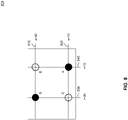
- FIGS. 7A and 7B illustrate operation of the first exemplary touchscreen according to an exemplary embodiment of the present disclosure.
- the first electrode pattern 200 illustrated in “light gray”
- the second electrode pattern 300 illustrated in “dark gray” are attached to form the touchscreen 400.
- the touchscreen 400 can operate in a row scanning mode of operation or in a column scanning mode of operation.
- the row scanning mode of operation one or more horizontal electrodes from among the horizontal electrodes 302.1 through 302.p are sequentially excited by a drive signal.
- the drive signal capacitively couples to one or more vertical electrodes from among the vertical electrodes 202.1 through 202.k. Transferred electrical charges or currents due to mutual capacitance(s) between the driven horizontal electrode and the one or more vertical electrodes are measured to detect a presence and/or a location of a touch from an operator, such as a finger of the operator, a hand of the operator, and/or other objects available to the operator, such as a stylus to provide an example.
- one or more vertical electrodes from among the vertical electrodes 202.1 through 202.k are sequentially excited by a drive signal.
- the drive signal capacitively couples to one or more horizontal electrodes from among the horizontal electrodes 302.1 through 302.p. Transferred electrical charges or currents due to mutual capacitance(s) between the driven vertical electrode and the one or more horizontal electrodes are measured to detect a presence and/or a location of a touch from an operator.
- the description to follow further describes the operation of the touchscreen 400 in the row scanning mode of operation. Those skilled in the relevant art(s) will recognize that the column scanning mode of operation operates in a similar manner without departing from the scope of the present disclosure.
- FIGS. 7A and 7B a horizontal electrode from among the horizontal electrodes 302.1 through 302. p is driven by an excitation signal which capacitively couples to all vertical electrodes 202.1 through 202.k.
- FIG. 7A illustrates capacitive coupling of the drive signal from horizontal electrode 302.2 and vertical electrode 202. k-1
- FIG. 7B illustrates capacitive coupling of the drive signal from horizontal electrode 302.2 and vertical electrode 202.k.
- a mutual capacitance "C M " is associated with each of the horizontal electrodes 302.1 through 302. p and a corresponding one of the vertical electrodes 202.1 through 202.k.
- r represents an index for a vertical electrode 202. r from among the vertical electrodes 202.1 through 202.k
- s represents an index of a horizontal electrode 302. s from among the horizontal electrodes 302.1 through 302. p
- FIGs. 2-7 illustrate only one specific construction and geometry of electrodes of a PCAP touchscreen.
- the floating islands are purely optional.
- the electrode material may be ITO, a metal mesh, silver nanowires, an intrinsically conductive polymer, or any other conductive material.
- the electrode geometry may include diamond shaped pads (as in FIGs. 1-7 ) or may simply divide the touch area into rectangular strips.
- the ideas presented below apply to any PCAP touchscreen with X and Y electrodes, that is to any touchscreen construction with a set of vertically oriented electrodes and with a set of horizontally oriented electrodes and associated self and mutual capacitances.
- FIG. 5 illustrates a conceptual circuit 500 for mutual-capacitance readout mode, or mutual-mode, according to example embodiments of the disclosure.
- a signal V DRIVE (t) excites vertical electrode r which couples through mutual capacitance C M (r,s) to horizontal sense electrode which in turn is connected to a current sensing circuit.
- the signal output voltage V OUT (t) is proportional to the charge on the integrating capacitor C SENSE .
- the excitation signal is connected to one electrode (electrode r) and the sensing circuit is connected to another electrode (electrode s) and the measured signal is proportional to the mutual capacitance C M (r,s).
- a touch reduces the value of C M (r,s).
- the notation ⁇ C M (r,s) represents touch induced changes in the measured mutual capacitance between vertical electrode “r” and horizontal electrode “s” relative to the baseline values C M (r,s). Water contaminants have the undesired effect of altering the measured touch signals ⁇ C M (r,s).
- FIG. 6 illustrates a conceptual circuit 600 for self-capacitance readout mode, or self-mode, according to example embodiments of the disclosure.
- self-capacitive readout mode a capacitance is measured for each electrode, not for electrode pairs.
- the notation C V S (r) represents the no-touch baseline self-capacitance measured for vertical electrode "r".
- ⁇ C V S (r) represents the touch induced change in the measured self-capacitance of electrode "r”.
- C H S (s) and ⁇ C H S (s) represent corresponding quantities for horizontal electrode "s”.
- Such a self-capacitance is measured by driving electrode "r” or "s” by an excitation voltage signal and measuring the resulting current or charge provided to the electrode by the driving circuitry.
- an electrode is simultaneously driven and sensed.
- a signal V DRIVE (t) at the positive high-gain differential amplifier input is via feedback reproduced at the negative differential amplifier input which in turn drives one electrode (electrode r or electrode s).
- the ground to the left of the electrode self-capacitance C S (r) or C S (s) includes stray capacitances from the electrode to ground as well as the grounding effect of any finger touch.
- a touch increases the value of C S (r) or C S (s).
- the change on integrating capacitor C SENSE is the same as the charge on C S (r) or C S (s), and hence the signal output voltage V OUT (t) is proportional to the charge C S (r) or C S (s). Note that in self-mode the excitation signal is delivered to the same electrode (r or s) that is sensed.
- Self-mode measurements are made with an excitation signal that transitions between a low voltage and a high voltage, and then back to the low voltage.
- the corresponding repetition frequency may be referred to as the "self-mode excitation drive frequency” or more briefly the “drive frequency”, is conventionally in the range from 10kHz to 100kHz.
- FIG. 8 illustrates an example 800 of mutual-mode advantage for multi-touches, according to example embodiments of the disclosure.
- a PCAP touchscreen with k vertical electrodes and p horizontal electrodes, there are k ⁇ p mutual-capacitance signals ⁇ C M (r,s) measured.
- ⁇ C M (r,s) measured.
- self-capacitance signals ⁇ C V S (r) and ⁇ C H S (s).
- there will be 5,000 mutual-capacitive signals ⁇ C M (r,s) but much fewer self-capacitive signals.
- controller electronics measures non-zero vertical-electrode self-capacitive signals ⁇ C V S (30) and ⁇ C V S (70) and non-zero horizontal-electrode self-capacitive signals ⁇ C H S (10) and ⁇ C H S (40).
- Self-mode has an advantage for water immunity over mutual-mode.
- An untouched drop of water on the surface of a PCAP touchscreen has essentially no effect on the baseline self-capacitive values C V S (r) and C H S (s), that is, self-capacitive signals ⁇ C V S (r) and ⁇ C H S (s) remain essentially zero.
- a splash of water on the touch surface is unlikely to trigger a false touch report.
- water drops not in contact with a touching finger generate no signals ⁇ C V S (r) and ⁇ C H S (s) and hence do not confuse touch recognition algorithms.
- a finger generates a touch signal because it is electrically grounded to the user's body while an electrically ungrounded water drop remains largely invisible to the electronics.
- FIG. 9 illustrates mutual-mode ghost effects in diagram 900, according to example embodiments of the disclosure.
- Water induced mutual-capacitive signals ⁇ C M (r,s) are not limited to electrode-intersection values (r,s) corresponding to water drop locations. For example consider the effects of a water drop whose area includes electrode-intersections corresponding to values (r, s+2) and (r+2,s), but not (r,s). See sketch below where the ellipse represents a water drop. Not only will the water drop induce non-zero mutual-capacitive signals ⁇ C M (r,s+2) and ⁇ C M (r+2,s), but also will induce a non-zero measured mutual-capacitive signal ⁇ C M (r,s).
- the term “ghost” signal may be used to describe such a non-zero mutual-capacitive signal ⁇ C M (r,s) that is measured by the electronics despite the lack of anything physical at the intersection of the "r” and “s” electrodes. In this case, the signal is of opposite algebraic sign than desired touch signals, and hence the more refined term “anti-ghost” may also be used. Such "ghost” or “anti-ghost” signal effects further complication the interpretation of mutual-capacitive signals ⁇ C M (r,s) when water is present.
- touch performance is a list of some key touch aspects of touch performance. Depending on the application, the requirements and relative importance of these touch performance attributes may vary.
- embodiments When water contaminants are present, embodiments obtain measurements in both self-mode and mutual-mode in a single measurement frame. Despite the corruption of mutual capacitive measurements ⁇ C M (r,s) by water contaminants, it is still possible to extract useful information from mutual-mode ⁇ C M (r,s) measurements that complement the information in the self-mode measurements ⁇ C V S (r) and ⁇ C H S (s).
- FIG. 10 illustrates a timing diagram 1000 of a measurement frame with both self-mode and mutual-mode measurements, according to example embodiments of the disclosure.
- a start-of-frame pulse initiates a measurement frame at time T0.
- the measurement frame has a duration after which another start-of-frame pulse at time T3 initiates the subsequent frame.
- the measurement frame duration T0-T3 is preferably too short to be perceived by humans.
- the measurement frame duration may be one hundredth of a second (10 milliseconds).
- touchscreen controller 120 may configure the electronics for touchscreen 110 to be in self-mode. As illustrated, the electronics for touchscreen 110 are in self-mode from time T0 to time T2, or in this example, about the first quarter of the measurement frame.
- touchscreen controller 120 may configure the electronics for touchscreen 110 to be in mutual-mode. As illustrated, touchscreen controller 120 may configure the electronics for touchscreen 110 to be in mutual-mode from time T2 to time T3, or the remainder of the measurement frame.
- touchscreen controller 120 may configure the electronics for touchscreen 110 to revert to pure mutual-mode once touchscreen controller 120 determines that touchscreen 110 is dry to improve mutual-mode performance either by reducing the time between measurement frames or allocating more time to mutual-mode for improved signal averaging.
- Some embodiments include determining a presence of a liquid on a touchscreen, using a mixed-mode measurement frame to obtain a self-mode measurement and a mutual-mode measurement, and detecting a touch on the touchscreen.
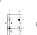
- FIG. 11 illustrates diagram 1100 demonstrating that mutual-mode may resolve self-mode ambiguities, according to example embodiments of the disclosure.
- touchscreen controller 120 enabling self-mode and mutual-mode measurements in a measurement frame
- Assume due to finger size and signal smearing effects of water contaminants, significantly non-zero values are measured for the vertical-electrode self-capacitive signals ⁇ C V S (r) for r 20, 21, ... 30, ...
- mask 1105 may be constructed of four sub-masks SM1-SM4, as follows.
- lower-left sub-mask SM1 may be defined for the set of electrode intersections (r,s) for which 20 ⁇ r ⁇ 40 and 0 ⁇ s ⁇ 20, namely by the intersection of the left set of electrodes with non-zero values ⁇ C V S (r) with the lower set of electrodes with non-zero values ⁇ C H S (s).
- Lower-right, upper-left and upper-right sub-masks SM2, SM3 and SM4 may be defined in a similar fashion.
- mutual-mode data e.g., data collected from electrodes of touchscreen 110 while touchscreen 110 is operating in mutual-mode
- touchscreen controller 120 may use mutual-mode data to validate a touch in at least one of the four sub-masks.
- mutual-mode measurements provide convincing data that there is indeed a touch in the upper-left sub-mask SM3
- it is clear that the ambiguity is resolved in favor of an upper-left touch B and a lower-right touch A, and not in favor of a lower-left ghost touch C and upper-right touch ghost touch D.
- mutual-mode data may be used by touch controller 120 to exclude the possibility of a touch in at least one of the four sub-masks. For example, if mutual-mode data indicate that there is no touch within the area corresponding to the upper-right sub-mask SM4, the ambiguity will be correctly resolved in favor of an upper-left touch B and a lower-right touch A.
- the self-mode measurement period from T0 to T2 precedes the mutual-mode measurement period from T2 to T3.
- This self-mode first measurement order is important if the mask is used to direct mutual-mode data acquisition, such as if the mutual-mode measurements are accelerated by collecting data for electrode intersections only within the masked area.
- the self-mode measurement precedes the mutual-mode measurement.
- data from the self-mode measurement are used to identify areas on the touchscreen from which the mutual-mode measurements are collected.
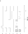
- FIG. 12 illustrates a timing diagram 1200 of a mixed-mode measurement frame with multiple self-mode drive frequencies, according to the invention.
- touchscreen controller 120 when the logic level of signal (c) is true (high), from time TO-T1, touchscreen controller 120 configures the electronics of touchscreen 110 to be in self-mode with higher drive frequency.
- touchscreen controller 120 may configure the electronics of touchscreen 110 to be configured in self-mode with a lower drive frequency.
- Timing diagram 1200 shows the same signals (a), (b), (c) and (d) as seen in FIG. 10 , but on an expanded horizontal time scale. Timing diagram 1200 also illustrates the pulse trains of signals (e) and (f) associated with the self-mode measurements at a higher drive frequency and a lower drive frequency, respectively. Alternatively, the lower frequency self-mode measurement may be performed first.
- the lower drive frequency associated with signals (d) and (f) is preferably in a frequency range for which little signal amplitude is lost due to lack of complete RC settling of signal propagating within the sensor. This may correspond to the conventional frequency range from 10kHz to 100kHz. This lower drive frequency may be optimized for mutual-mode measurements under dry conditions.
- the higher drive frequency associated with signal (c) is preferably sufficiently high to provide reduced touch signal smearing. For example, higher drive frequencies in the range from 100kHz to 500kHz are of interest. While not optimal for mutual-mode measurements under dry conditions, the highfrequency may be optimized for touch coordinate determinations under wet conditions.
- FIG. 17 illustrates diagram 1700 with self-capacitance touch measurements captured at both a high frequency and a low frequency.
- the plot 1710 displays self-capacitances measured at a higher drive frequency of 357kHz while plot 1720 displays self-capacitances measured at a lower drive frequency of 25kHz.
- the horizontal axis is the vertical electrode index r. The peaks in both plots correspond to the location of a touch.
- the peaks are not clean but rather have tails resulting from touch signals being smeared out by signal propagation through the water. Furthermore, the significant difference in the signal shapes seen in the two plots is a signature of the presence of water contamination.
- the ratio of the higher drive frequency to the lower drive frequency is large, such as having a higher drive frequency that is five or ten times that of the lower drive frequency.
- a higher drive frequency may be chosen at which significant signal amplitude loss occurs as a result of incomplete RC settling.
- the disadvantage of reduced signal amplitude may be more than compensated by the benefit of reduced influence of water contaminants on the measured self-mode signals.
- Measuring self-mode signals ⁇ C V S (r) and ⁇ C H S (s) at a third drive frequency may provide yet further information with which to separate touch and water induced signals.
- an additional plot of self-capacitance data (not shown) measured at say 100kHz would provide an intermediate shape between those shown for 357kHz and 25kHz and would provide more information on how measured self-capacitance signals vary with frequency.
- Such additional or redundant data provides algorithms with more information to verify or refine interpretations of signals in terms of desired touch information and distortions due to water.
- Additional drive frequencies can also be used up to and including an approximation to a frequency sweep of self-mode signals ⁇ C V S (r) and ⁇ C H S (s).
- the self-mode measurement comprises data collected at two or more drive frequencies.
- a first drive frequency of the two or more drive frequencies is at least five times that of a second drive frequency of the two or more drive frequencies.
- the first drive frequency is less than or equal to ten times that of the second drive frequency.
- the first drive frequency of the two or more drive frequencies is greater than or equal to 100kHz. In another embodiment, the first drive frequency is less than or equal to 500kHz.
- touch controller 120 may transition from a mixed-mode measurement frame to a pure self-mode measurement frame, thus more time is available for self-mode measurement signal averaging.
- a third self-mode measurement is added and the mutual-mode time for the mutual-mode measurement of the mixed-mode measurement frame is reduced accordingly.
- Some embodiments include transitioning to a pure self-mode measurement frame.
- the controller is configured to simultaneously measure horizontal-electrodes and vertical-electrodes.
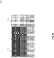
- FIG. 13 illustrates diagram 1300 of fluid measurements on a touchscreen based on a mixed mode measurement frame, according to example embodiments of the disclosure.
- the mixed mode measurement frame operation generates data richer in information about the nature of any water contamination that may be present on touchscreen 110.
- mutual-mode data provides more information about water contaminants on the touchscreen surface. Such information may lead to better algorithms for deciding when to switch between dry and wet modes of operation.
- mutual-mode data ⁇ C M (r,s) and self-mode data ⁇ C H S (s) and ⁇ C V S (r) are shown in diagram 1300.
- the ⁇ C M (r,s) data 1310 is color coded where zero is represented by a neutral gray and negative values by lighter gray (as expected from valid touches), and positive values by darker gray (no valid touches).
- Data was collected when several drops of water were on a PCAP touchscreen surface (e.g., touchscreen 110). A touch was present in the upper-right water drop labeled "A". The other water drops, such as the one labeled "B" remained electrically isolated from the touched water drop and the touch.
- the self-mode measurement including measurements from a lower and a higher drive frequency in conjunction with the mutual-mode measurements are used to estimate the level/degree and nature of water contamination as well as locations of water contamination.
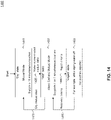
- FIG. 14 illustrates a mode state machine 1400, according to example embodiments of the disclosure.
- State machine 1400 illustrates a mutual-mode "dry” state 1410, a mixed self and mutual “wet” state 1430, and an optional "reject” state 1450.
- State machine 1400 is initialized presuming the touchscreen is dry. That is, touchscreen controller 120 initially configures the electronics of touchscreen 110 to begin in "dry” state 1410.
- the exact nature of "dry" state 1410 may vary depending on the needs of the application. For example, “dry” state 1410 may use pure mutual-mode measurements in a measurement frame, and may support 10 or more simultaneous touches with instantaneous response as perceived by users.
- touchscreen controller 120 may determine (e.g., based on a mixed reading of both positive and negative values mutual mode data as described above) that water contamination is present and transition to "wet" state 1430.
- a mixed mode measurement frame is implemented in the wet state 1430.
- the exact nature of the wet state may vary depending on the needs of the application.
- the wet state may use both higher frequency and lower frequency self-modes as well as mutual-mode during each measurement frame.
- such a mixed mode measurement frame provides acceptable touch performance for one or two touches even in the presence of water contamination. If mutual mode data, and/or the comparison of a higher-frequency self-mode data and lower-frequency self-mode data, indicate a sufficient level of water contamination, state machine 1400 remains in "wet" state 1430.
- state-machine 1400 when the mutual-mode data, and/or the comparison of a higher-frequency self-mode data and lower-frequency self-mode data, indicates that the touchscreen has, or has been, dried off (e.g., touchscreen controller 120 determines that based on the data collected, the water contamination on touchscreen 110 satisfies a threshold value), state-machine 1400 returns from "wet" state 1430 to "dry” state 1410.
- "Reject" state 1450 is a state in which no touches are reported and touchscreen 110 is deliberately unresponsive. Such a reject state may be desirable under certain circumstances such as when a user wipes water contaminants off touchscreen 110 with a cloth. During such wiping, the user wants to clean off the touchscreen surface without activating any touch buttons.
- wipe and clean operations may be determined by an initial presence of water as seen in mutual-mode data (and/or the comparison of a higher-frequency self-mode data and lower-frequency self-mode data), as well as large and moving touch areas as seen in self-mode data. Such signatures may be used to define reject criteria that cause the state machine to transition between "wet" state 1430 and "reject” state 1450.
- touchscreen controller may determine to transition from "reject" state 1450 to "wet” state 1430.
- the determination may be based on contrasting signatures such as no touches in the self-mode data and reduced water contamination in the mutual-mode data, and/or the passage of a settable amount of time. The latter may be used to define recovery criteria for transitioning from "reject" state 1450 back to "wet” state 1430.
- the controller is configured to determine using the mutual-mode measurement of the mixed-mode measurement frame, that the touchscreen is dry; and transition from the mixed-mode measurement frame to a mutual-mode only measurement frame. In another embodiment, the controller is further configured to detect a reject criterion, and transition from the mixed-mode measurement frame to a reject state.
- State machine 1400 is based on data from one measurement frame. More information about a touch and/or water contamination is contained in a time sequence of multiple measurement frames. In other words, multi-frame or inter-frame correlations provide a means to improve touch algorithm performance when water contaminants are present. Such algorithms may be combined with the methods described above.
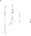
- FIG. 15 illustrates a method for a touch algorithm 1500 based on multiple self-mode measurement frames, according to example embodiments of the disclosure.
- T-1 and T refer to two successive frames for which self-mode measurements are collected and saved.
- the stored data for frame T-1 and T respectively are made available for processing by algorithm 1500.
- algorithm step 1530 patterns of non-zero self-mode signals ⁇ C V S (r) and ⁇ C H S (s) for frame T-1 and frame T are compared and a correlation parameter is computed for each candidate touch. If the correlation parameter for a candidate touch satisfies a settable threshold value (e.g., exceeds a threshold value) then the process moves to step 1540 where touch coordinates are reported.
- a settable threshold value e.g., exceeds a threshold value
- Touch algorithm 1500 illustrates the use of data from more than one frame in the detection and locating of touches.
- touch algorithm 1500 can be generalized and refined in many ways such as the use of mixed-mode data from more than one measurement frame, self-mode and/or mixed-mode data from three or more frames, use of various correlation methods, etc. Any such method for combining information between frames may be used with the above described methods in which self-mode data is collected within each frame.
- PCAP touchscreen 110 is electrically coupled to touchscreen controller 120.
- touchscreen controller 120 Within touchscreen controller 120 is analog circuitry as well as firmware 125 that may control many of the features discussed above.
- firmware 125 computes touch coordinates that are communicated to application 135 (e.g., software) running on computing device 130 (e.g., a host computer).
- application 135 may perform many other functions in addition to receiving touch information.
- application 135 may determine what images appear on a display behind touchscreen 110. There are scenarios in which communication between firmware 125 and application 135 extend beyond conventional transmission of touch coordinates.
- Firmware 125 may quantify water contamination on a touchscreen. Particularly in our fast-self/slow-self/mutual scan schemes described in the '496 Application above, the firmware 125 has access to a significant amount of information about the existence, nature and location of water contaminants.
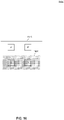
- FIG. 16 illustrates an application adjustment diagram 1600 based on firmware-level data, according to example embodiments of the disclosure.
- Application adjustment diagram 1600 includes a touchscreen area 1610 which may be the same as touchscreen 110, and a portion of the touchscreen that has water contamination, area 1620.
- a touchscreen area 1610 which may be the same as touchscreen 110
- a portion of the touchscreen that has water contamination, area 1620 For example, if before a touch, mutual-mode measurements show much scatter (e.g., positive and negative measurements intermingled as described in FIG. 13 ) above and below a baseline value (e.g., acceptable threshold value) for area 1620, and at the same time minimal signals are detected in self-mode measurements, firmware 125 may infer that area 1620 is contaminated with water while the upper half of the touchscreen area 1610 remains dry.
- a baseline value e.g., acceptable threshold value
- a digital communication protocol may be developed for communicating firmware 125-derived information about water contaminates to computing device 130 and/or application 135.
- embodiments include transmitting water contaminant information received solely from the firmware 125, to computing device 130, where computing device 130 takes actions at the system level in response to the received water contaminant information.
- application 135 may move critical touch buttons out of the water contaminated area, area 1620 into the dry area of the touchscreen area 1610. Note that critical touch buttons "A” and “B” are moved to new locations " A' " and " B' " in response to water contamination in area 1620.
- system 100 may take action to remove the water contamination in response to firmware 125-provided information such as activation of windshield wipers, initiation of a spray of distilled water to wash off more conductive salt water, activation of an air blower, etc.
- the controller transmits mutual-mode and/or self-mode data regarding water contamination to a computing device, wherein the computing device adjusts an application associated with the water contamination.
- firmware of the controller transmits the mutual-mode and/or self-mode data to the computing device.
- Computer system 1800 can be any well-known computer capable of performing the functions described herein.
- Computer system 1800 may be internal or external to system 100 as discussed above.
- Computer system 1800 may perform some or all of the functions of FIGs. 1 , and 10-16 , for example.
- Computer system 1800 includes one or more processors (also called central processing units, or CPUs), such as a processor 1804.
- processors also called central processing units, or CPUs
- Processor 1804 is connected to communication infrastructure 1806 (e.g., a bus.)
- One or more processors 1804 may each be a graphics processing unit (GPU).
- a GPU is a processor that is a specialized electronic circuit designed to process mathematically intensive applications.
- the GPU may have a parallel structure that is efficient for parallel processing of large blocks of data, such as mathematically intensive data common to computer graphics applications, images, videos, etc.
- Computer system 1800 also includes user input/output interface(s) 1802.
- Devices such as monitors, keyboards, pointing devices, etc., may communicate with communication infrastructure 1806 through user input/output interface(s) 1802.
- Computer system 1800 also includes a main or primary memory 1808, such as random access memory (RAM).
- Main memory 1808 may include one or more levels of cache.
- Main memory 1808 has stored therein control logic (i.e., computer software) and/or data.
- Computer system 1800 may also include one or more secondary storage devices or memory 1810.
- Secondary memory 1810 may include, for example, a hard disk drive 1812 and/or a removable storage device or drive 1814.
- Removable storage drive 1814 may be a floppy disk drive, a magnetic tape drive, a compact disk drive, an optical storage device, tape backup device, and/or any other storage device/drive.
- Removable storage drive 1814 may interact with a removable storage unit 1818.
- Removable storage unit 1818 includes a computer usable or readable storage device having stored thereon computer software (control logic) and/or data.
- Removable storage unit 1818 may be a floppy disk, magnetic tape, compact disk, DVD, optical storage disk, and/ any other computer data storage device.
- Removable storage drive 414 reads from and/or writes to removable storage unit 1818 in a well-known manner.
- secondary memory 1810 may include other means, instrumentalities or other approaches for allowing computer programs and/or other instructions and/or data to be accessed by computer system 1800.
- Such means, instrumentalities or other approaches may include, for example, a removable storage unit 1822 and an interface 1820.
- the removable storage unit 1822 and the interface 1820 may include a program cartridge and cartridge interface (such as that found in video game devices), a removable memory chip (such as an EPROM or PROM) and associated socket, a memory stick and USB port, a memory card and associated memory card slot, and/or any other removable storage unit and associated interface.
- Computer system 1800 may further include a communication or network interface 1824.
- Communication interface 1824 enables computer system 1800 to communicate and interact with any combination of remote devices, remote networks, remote entities, etc. (individually and collectively referenced by reference number 1828).
- communication interface 1824 may allow computer system 1800 to communicate with remote devices 1828 over communications path 1826, which may be wired and/or wireless, and which may include any combination of LANs, WANs, the Internet, etc. Control logic and/or data may be transmitted to and from computer system 1800 via communication path 1826.
- a tangible, non-transitory apparatus or article of manufacture comprising a tangible, non-transitory computer useable or readable medium having control logic (software) stored thereon is also referred to herein as a computer program product or program storage device.
- control logic software stored thereon
- control logic when executed by one or more data processing devices (such as computer system 1800), causes such data processing devices to operate as described herein.
Landscapes
- Engineering & Computer Science (AREA)
- General Engineering & Computer Science (AREA)
- Theoretical Computer Science (AREA)
- Human Computer Interaction (AREA)
- Physics & Mathematics (AREA)
- General Physics & Mathematics (AREA)
- Microelectronics & Electronic Packaging (AREA)
- Position Input By Displaying (AREA)
- Electronic Switches (AREA)
Claims (15)
- Système tactile capacitif projeté (100), comprenant :un écran tactile (110, 400) ; etun contrôleur (120) couplé à l'écran tactile, le contrôleur étant configuré pour :obtenir des mesures durant une trame de mesure en mode mixte comprenant, séquentiellement, une mesure en mode propre et une mesure en mode mutuel ; etsur la base des mesures obtenues, déterminer un contact sur l'écran tactile en présence d'une contamination aqueuse sur l'écran tactile,caractérisé en ce quela mesure en mode propre comprend, séquentiellement dans la trame de mesure en mode mixte, une mesure de fréquence d'entraînement inférieure et une mesure de fréquence d'entraînement supérieure, etune fréquence d'entraînement supérieure de la mesure de fréquence d'entraînement supérieure est au moins cinq à dix fois plus élevée qu'une fréquence d'entraînement inférieure de la mesure de fréquence d'entraînement inférieure.
- Système tactile capacitif projeté selon la revendication 1, dans lequel la fréquence d'entraînement inférieure de la mesure de fréquence d'entraînement inférieure est comprise dans une plage de 10 kHz à 100 kHz.
- Système tactile capacitif projeté selon la revendication 1, dans lequel la fréquence d'entraînement supérieure de la mesure de fréquence d'entraînement supérieure est comprise dans une plage de 100 kHz à 500 kHz.
- Système tactile capacitif projeté selon la revendication 1, dans lequel le contrôleur (120) est en outre configuré pour :
mesurer la contamination aqueuse, sur la base de la mesure de fréquence d'entraînement inférieure et de la mesure de fréquence d'entraînement supérieure. - Système tactile capacitif projeté selon la revendication 4, dans lequel, pour mesurer la contamination aqueuse, le contrôleur (120) est configuré pour :déterminer la quantité de la contamination aqueuse ; etdéterminer la position de la contamination aqueuse.
- Système tactile capacitif projeté selon la revendication 1, dans lequel la mesure en mode propre précède la mesure en mode mutuel.
- Système tactile capacitif projeté selon la revendication 6, dans lequel le contrôleur (120) est en outre configuré pour utiliser des données de la mesure en mode propre pour identifier des zones de l'écran tactile où la mesure en mode mutuel est collectée.
- Système tactile capacitif projeté selon la revendication 7, dans lequel, pour identifier les zones de l'écran tactile (110, 400) où la mesure en mode mutuel est collectée, le contrôleur (120) est configuré pour construire un masque sur la base de la mesure en mode propre.
- Système tactile capacitif projeté selon la revendication 1, dans lequel la mesure en mode propre comprend une troisième mesure de fréquence d'entraînement, dans lequel une troisième fréquence d'entraînement correspondante de la troisième mesure de fréquence d'entraînement est comprise entre la fréquence d'entraînement inférieure et la fréquence d'entraînement supérieure.
- Procédé comprenant :l'obtention de mesures provenant d'un écran tactile capacitif projeté (110, 400) durant une trame de mesure en mode mixte comprenant, séquentiellement, une mesure en mode propre et une mesure en mode mutuel ; etsur la base des mesures obtenues, la détermination d'un contact sur l'écran tactile en présence d'une contamination aqueuse sur l'écran tactile,caractérisé en ce quela mesure en mode propre comprend, séquentiellement dans la trame de mesure en mode mixte, une mesure de fréquence d'entraînement inférieure et une mesure de fréquence d'entraînement supérieure, etune fréquence d'entraînement supérieure de la mesure de fréquence d'entraînement supérieure est au moins cinq à dix fois plus élevée qu'une fréquence d'entraînement inférieure de la mesure de fréquence d'entraînement inférieure.
- Procédé selon la revendication 10, dans lequel la fréquence d'entraînement inférieure de la mesure de fréquence d'entraînement inférieure est comprise dans une plage de 10 kHz à 100 kHz, et la fréquence d'entraînement supérieure de la mesure de fréquence d'entraînement supérieure est comprise dans une plage de 100 kHz à 500 kHz.
- Procédé selon la revendication 10, comprenant en outre la mesure de la contamination aqueuse, sur la base de la mesure de fréquence d'entraînement inférieure et de la mesure de fréquence d'entraînement supérieure.
- Procédé selon la revendication 12, dans lequel la mesure de la contamination aqueuse comprend :la détermination de la quantité de contamination aqueuse ; etla détermination de la position de la contamination aqueuse.
- Procédé selon la revendication 10, comprenant en outre l'utilisation de données de la mesure en mode propre précédant la mesure en mode mutuel pour identifier des zones de l'écran tactile où la mesure en mode mutuel est collectée.
- Support non volatile lisible par un ordinateur, sur lequel sont stockées des instructions qui, lorsqu'elles sont exécutées par un processeur d'un premier dispositif électronique, commandent au processeur de mettre en œuvre des opérations, les opérations comprenant :l'obtention de mesures provenant d'un écran tactile capacitif projeté (110, 400) durant une trame de mesure en mode mixte comprenant, séquentiellement, une mesure en mode propre et une mesure en mode mutuel ; etsur la base des mesures obtenues, la détermination d'un contact sur l'écran tactile en présence d'une contamination aqueuse sur l'écran tactile,caractérisé en ce quela mesure en mode propre comprend, séquentiellement dans la trame de mesure en mode mixte, une mesure de fréquence d'entraînement inférieure et une mesure de fréquence d'entraînement supérieure, etune fréquence d'entraînement supérieure de la mesure de fréquence d'entraînement supérieure est au moins cinq à dix fois plus élevée qu'une fréquence d'entraînement inférieure de la mesure de fréquence d'entraînement inférieure.
Applications Claiming Priority (3)
| Application Number | Priority Date | Filing Date | Title |
|---|---|---|---|
| US201762508549P | 2017-05-19 | 2017-05-19 | |
| US15/982,124 US10901557B2 (en) | 2017-05-19 | 2018-05-17 | PCAP with enhanced immunity to water contaminants |
| PCT/US2018/033341 WO2018213673A1 (fr) | 2017-05-19 | 2018-05-18 | Pcap présentant une immunité améliorée vis-à-vis des contaminants de l'eau |
Publications (2)
| Publication Number | Publication Date |
|---|---|
| EP3625657A1 EP3625657A1 (fr) | 2020-03-25 |
| EP3625657B1 true EP3625657B1 (fr) | 2022-10-12 |
Family
ID=64271681
Family Applications (1)
| Application Number | Title | Priority Date | Filing Date |
|---|---|---|---|
| EP18729853.4A Active EP3625657B1 (fr) | 2017-05-19 | 2018-05-18 | Pcap présentant une immunité améliorée vis-à-vis des contaminants de l'eau |
Country Status (5)
| Country | Link |
|---|---|
| US (2) | US10901557B2 (fr) |
| EP (1) | EP3625657B1 (fr) |
| CN (1) | CN110447007B (fr) |
| TW (1) | TW201901387A (fr) |
| WO (1) | WO2018213673A1 (fr) |
Families Citing this family (9)
| Publication number | Priority date | Publication date | Assignee | Title |
|---|---|---|---|---|
| TWI765056B (zh) * | 2018-06-05 | 2022-05-21 | 新益先創科技股份有限公司 | 位置感測裝置與位置感測方法 |
| WO2020028542A1 (fr) | 2018-08-02 | 2020-02-06 | Elo Touch Solutions, Inc. | Écran tactile capacitif projeté (pcap) résistant à l'eau |
| WO2020056499A1 (fr) | 2018-09-17 | 2020-03-26 | Johnson Systems Inc. | Système d'éclairage et procédé associé |
| US10928946B2 (en) * | 2019-02-15 | 2021-02-23 | Dell Products L.P. | Touchscreen stylus and display module interface |
| CN111610872B (zh) * | 2019-02-26 | 2023-07-07 | 敦泰电子有限公司 | 触控控制方法、电路系统及触控装置 |
| CN111610873B (zh) * | 2019-02-26 | 2023-10-27 | 敦泰电子有限公司 | 触控控制方法、电路系统及触控装置 |
| KR102308610B1 (ko) * | 2020-03-05 | 2021-10-06 | 주식회사 지2터치 | 이물질 검출 기능을 갖는 터치 스크린 패널 및 방법 |
| US11300536B1 (en) | 2020-12-18 | 2022-04-12 | Cypress Semiconductor Corporation | Non-contact liquid sensing technologies |
| CN115497396A (zh) * | 2022-10-17 | 2022-12-20 | 业成科技(成都)有限公司 | 显示面板、电子装置、触控面板及其制备方法 |
Family Cites Families (16)
| Publication number | Priority date | Publication date | Assignee | Title |
|---|---|---|---|---|
| US7253723B2 (en) * | 2003-05-19 | 2007-08-07 | Donnelly Corporation | Mirror assembly |
| TW201203041A (en) * | 2010-03-05 | 2012-01-16 | Canatu Oy | A touch sensitive film and a touch sensing device |
| US8624870B2 (en) * | 2010-04-22 | 2014-01-07 | Maxim Integrated Products, Inc. | System for and method of transferring charge to convert capacitance to voltage for touchscreen controllers |
| TWI447632B (zh) * | 2012-03-09 | 2014-08-01 | Orise Technology Co Ltd | 電容式多點觸控系統的驅動頻率挑選方法 |
| TWI463386B (zh) | 2012-04-03 | 2014-12-01 | Elan Microelectronics Corp | A method and an apparatus for improving noise interference of a capacitive touch device |
| US8816985B1 (en) | 2012-09-20 | 2014-08-26 | Cypress Semiconductor Corporation | Methods and apparatus to detect a touch pattern |
| CN112379792A (zh) * | 2014-10-27 | 2021-02-19 | 苹果公司 | 像素化自电容水排斥 |
| CN105938404B (zh) * | 2015-03-06 | 2020-10-30 | 意法半导体股份有限公司 | 用于触摸屏幕感应的方法和设备、对应的装置和计算机程序产品 |
| US10120498B2 (en) * | 2015-06-22 | 2018-11-06 | Sigmasense, Llc. | Multi-touch sensor and electrostatic pen digitizing system utilizing simultaneous functions for improved performance |
| US9740352B2 (en) | 2015-09-30 | 2017-08-22 | Elo Touch Solutions, Inc. | Supporting multiple users on a large scale projected capacitive touchscreen |
| JP2017091224A (ja) | 2015-11-10 | 2017-05-25 | 株式会社ジャパンディスプレイ | タッチ検出機能付き表示装置 |
| US9864468B2 (en) * | 2016-06-09 | 2018-01-09 | Stmicroelectronics Asia Pacific Pte Ltd | Multi-touch integrity sensing for capacitive touch screen |
| US9707935B1 (en) * | 2016-06-30 | 2017-07-18 | Nicholas J. Singer | Windshield touch and clean system |
| US10365764B2 (en) * | 2016-07-11 | 2019-07-30 | Stmicroelectronics Asia Pacific Pte Ltd | Water rejection for capacitive touch screen |
| US10969902B2 (en) | 2016-07-19 | 2021-04-06 | Elo Touch Solutions, Inc. | Projected-capacitive (PCAP) touchscreen |
| US10642418B2 (en) * | 2017-04-20 | 2020-05-05 | Apple Inc. | Finger tracking in wet environment |
-
2018
- 2018-05-17 US US15/982,124 patent/US10901557B2/en active Active
- 2018-05-18 EP EP18729853.4A patent/EP3625657B1/fr active Active
- 2018-05-18 WO PCT/US2018/033341 patent/WO2018213673A1/fr active Application Filing
- 2018-05-18 TW TW107117130A patent/TW201901387A/zh unknown
- 2018-05-18 CN CN201880020524.3A patent/CN110447007B/zh active Active
-
2021
- 2021-01-14 US US17/149,121 patent/US20210132741A1/en not_active Abandoned
Also Published As
| Publication number | Publication date |
|---|---|
| WO2018213673A1 (fr) | 2018-11-22 |
| EP3625657A1 (fr) | 2020-03-25 |
| US20210132741A1 (en) | 2021-05-06 |
| CN110447007B (zh) | 2024-03-26 |
| US10901557B2 (en) | 2021-01-26 |
| CN110447007A (zh) | 2019-11-12 |
| US20180335870A1 (en) | 2018-11-22 |
| TW201901387A (zh) | 2019-01-01 |
Similar Documents
| Publication | Publication Date | Title |
|---|---|---|
| EP3625657B1 (fr) | Pcap présentant une immunité améliorée vis-à-vis des contaminants de l'eau | |
| US10031621B2 (en) | Hover and touch detection for a digitizer | |
| US9417728B2 (en) | Predictive touch surface scanning | |
| EP2430757B1 (fr) | Dispositif de détection capacitive | |
| US8723825B2 (en) | Predictive touch surface scanning | |
| EP3106967B1 (fr) | Écran tactile multipoints | |
| CN106155409B (zh) | 用于模式变化的电容性度量处理 | |
| US9575602B1 (en) | Multi-touch disambiguation | |
| US11314355B2 (en) | Capacitive sensor patterns | |
| CN105045445B (zh) | 用于噪声测量的驱动传感器电极 | |
| US20120182225A1 (en) | Detection of Predetermined Objects with Capacitive Touchscreens or Touch Panels | |
| US9606670B2 (en) | Real-time spectral noise monitoring for proximity sensing device | |
| KR20140010859A (ko) | 고속 패널 스캐닝을 위한 이득 정정 | |
| WO2007144881A1 (fr) | Reconnaissance tactile pour numériseur | |
| US20140160056A1 (en) | Sensor device and method for detecting proximity events | |
| JP2015032276A (ja) | 指示入力装置、指示入力検出方法、プログラムおよび記録媒体 | |
| US10318785B2 (en) | Creation of virtual intersection points on a touchscreen to permit static, non swiping fingerprint user authentication | |
| US10528178B2 (en) | Capacitive touch sensing with conductivity type determination | |
| TW201435700A (zh) | 具有多頻和重心電容式偵測之多點觸控觸覺裝置 |
Legal Events
| Date | Code | Title | Description |
|---|---|---|---|
| STAA | Information on the status of an ep patent application or granted ep patent |
Free format text: STATUS: UNKNOWN |
|
| STAA | Information on the status of an ep patent application or granted ep patent |
Free format text: STATUS: THE INTERNATIONAL PUBLICATION HAS BEEN MADE |
|
| PUAI | Public reference made under article 153(3) epc to a published international application that has entered the european phase |
Free format text: ORIGINAL CODE: 0009012 |
|
| STAA | Information on the status of an ep patent application or granted ep patent |
Free format text: STATUS: REQUEST FOR EXAMINATION WAS MADE |
|
| 17P | Request for examination filed |
Effective date: 20191001 |
|
| AK | Designated contracting states |
Kind code of ref document: A1 Designated state(s): AL AT BE BG CH CY CZ DE DK EE ES FI FR GB GR HR HU IE IS IT LI LT LU LV MC MK MT NL NO PL PT RO RS SE SI SK SM TR |
|
| AX | Request for extension of the european patent |
Extension state: BA ME |
|
| DAV | Request for validation of the european patent (deleted) | ||
| DAX | Request for extension of the european patent (deleted) | ||
| STAA | Information on the status of an ep patent application or granted ep patent |
Free format text: STATUS: EXAMINATION IS IN PROGRESS |
|
| 17Q | First examination report despatched |
Effective date: 20211202 |
|
| GRAP | Despatch of communication of intention to grant a patent |
Free format text: ORIGINAL CODE: EPIDOSNIGR1 |
|
| STAA | Information on the status of an ep patent application or granted ep patent |
Free format text: STATUS: GRANT OF PATENT IS INTENDED |
|
| INTG | Intention to grant announced |
Effective date: 20220517 |
|
| GRAS | Grant fee paid |
Free format text: ORIGINAL CODE: EPIDOSNIGR3 |
|
| GRAA | (expected) grant |
Free format text: ORIGINAL CODE: 0009210 |
|
| STAA | Information on the status of an ep patent application or granted ep patent |
Free format text: STATUS: THE PATENT HAS BEEN GRANTED |
|
| AK | Designated contracting states |
Kind code of ref document: B1 Designated state(s): AL AT BE BG CH CY CZ DE DK EE ES FI FR GB GR HR HU IE IS IT LI LT LU LV MC MK MT NL NO PL PT RO RS SE SI SK SM TR |
|
| REG | Reference to a national code |
Ref country code: GB Ref legal event code: FG4D |
|
| REG | Reference to a national code |
Ref country code: CH Ref legal event code: EP |
|
| REG | Reference to a national code |
Ref country code: DE Ref legal event code: R096 Ref document number: 602018041670 Country of ref document: DE |
|
| REG | Reference to a national code |
Ref country code: IE Ref legal event code: FG4D |
|
| REG | Reference to a national code |
Ref country code: AT Ref legal event code: REF Ref document number: 1524564 Country of ref document: AT Kind code of ref document: T Effective date: 20221115 |
|
| REG | Reference to a national code |
Ref country code: LT Ref legal event code: MG9D |
|
| REG | Reference to a national code |
Ref country code: NL Ref legal event code: MP Effective date: 20221012 |
|
| REG | Reference to a national code |
Ref country code: AT Ref legal event code: MK05 Ref document number: 1524564 Country of ref document: AT Kind code of ref document: T Effective date: 20221012 |
|
| PG25 | Lapsed in a contracting state [announced via postgrant information from national office to epo] |
Ref country code: NL Free format text: LAPSE BECAUSE OF FAILURE TO SUBMIT A TRANSLATION OF THE DESCRIPTION OR TO PAY THE FEE WITHIN THE PRESCRIBED TIME-LIMIT Effective date: 20221012 |
|
| PG25 | Lapsed in a contracting state [announced via postgrant information from national office to epo] |
Ref country code: SE Free format text: LAPSE BECAUSE OF FAILURE TO SUBMIT A TRANSLATION OF THE DESCRIPTION OR TO PAY THE FEE WITHIN THE PRESCRIBED TIME-LIMIT Effective date: 20221012 Ref country code: PT Free format text: LAPSE BECAUSE OF FAILURE TO SUBMIT A TRANSLATION OF THE DESCRIPTION OR TO PAY THE FEE WITHIN THE PRESCRIBED TIME-LIMIT Effective date: 20230213 Ref country code: NO Free format text: LAPSE BECAUSE OF FAILURE TO SUBMIT A TRANSLATION OF THE DESCRIPTION OR TO PAY THE FEE WITHIN THE PRESCRIBED TIME-LIMIT Effective date: 20230112 Ref country code: LT Free format text: LAPSE BECAUSE OF FAILURE TO SUBMIT A TRANSLATION OF THE DESCRIPTION OR TO PAY THE FEE WITHIN THE PRESCRIBED TIME-LIMIT Effective date: 20221012 Ref country code: FI Free format text: LAPSE BECAUSE OF FAILURE TO SUBMIT A TRANSLATION OF THE DESCRIPTION OR TO PAY THE FEE WITHIN THE PRESCRIBED TIME-LIMIT Effective date: 20221012 Ref country code: ES Free format text: LAPSE BECAUSE OF FAILURE TO SUBMIT A TRANSLATION OF THE DESCRIPTION OR TO PAY THE FEE WITHIN THE PRESCRIBED TIME-LIMIT Effective date: 20221012 Ref country code: AT Free format text: LAPSE BECAUSE OF FAILURE TO SUBMIT A TRANSLATION OF THE DESCRIPTION OR TO PAY THE FEE WITHIN THE PRESCRIBED TIME-LIMIT Effective date: 20221012 |
|
| PG25 | Lapsed in a contracting state [announced via postgrant information from national office to epo] |
Ref country code: RS Free format text: LAPSE BECAUSE OF FAILURE TO SUBMIT A TRANSLATION OF THE DESCRIPTION OR TO PAY THE FEE WITHIN THE PRESCRIBED TIME-LIMIT Effective date: 20221012 Ref country code: PL Free format text: LAPSE BECAUSE OF FAILURE TO SUBMIT A TRANSLATION OF THE DESCRIPTION OR TO PAY THE FEE WITHIN THE PRESCRIBED TIME-LIMIT Effective date: 20221012 Ref country code: LV Free format text: LAPSE BECAUSE OF FAILURE TO SUBMIT A TRANSLATION OF THE DESCRIPTION OR TO PAY THE FEE WITHIN THE PRESCRIBED TIME-LIMIT Effective date: 20221012 Ref country code: IS Free format text: LAPSE BECAUSE OF FAILURE TO SUBMIT A TRANSLATION OF THE DESCRIPTION OR TO PAY THE FEE WITHIN THE PRESCRIBED TIME-LIMIT Effective date: 20230212 Ref country code: HR Free format text: LAPSE BECAUSE OF FAILURE TO SUBMIT A TRANSLATION OF THE DESCRIPTION OR TO PAY THE FEE WITHIN THE PRESCRIBED TIME-LIMIT Effective date: 20221012 Ref country code: GR Free format text: LAPSE BECAUSE OF FAILURE TO SUBMIT A TRANSLATION OF THE DESCRIPTION OR TO PAY THE FEE WITHIN THE PRESCRIBED TIME-LIMIT Effective date: 20230113 |
|
| P01 | Opt-out of the competence of the unified patent court (upc) registered |
Effective date: 20230526 |
|
| REG | Reference to a national code |
Ref country code: DE Ref legal event code: R097 Ref document number: 602018041670 Country of ref document: DE |
|
| PG25 | Lapsed in a contracting state [announced via postgrant information from national office to epo] |
Ref country code: SM Free format text: LAPSE BECAUSE OF FAILURE TO SUBMIT A TRANSLATION OF THE DESCRIPTION OR TO PAY THE FEE WITHIN THE PRESCRIBED TIME-LIMIT Effective date: 20221012 Ref country code: RO Free format text: LAPSE BECAUSE OF FAILURE TO SUBMIT A TRANSLATION OF THE DESCRIPTION OR TO PAY THE FEE WITHIN THE PRESCRIBED TIME-LIMIT Effective date: 20221012 Ref country code: EE Free format text: LAPSE BECAUSE OF FAILURE TO SUBMIT A TRANSLATION OF THE DESCRIPTION OR TO PAY THE FEE WITHIN THE PRESCRIBED TIME-LIMIT Effective date: 20221012 Ref country code: DK Free format text: LAPSE BECAUSE OF FAILURE TO SUBMIT A TRANSLATION OF THE DESCRIPTION OR TO PAY THE FEE WITHIN THE PRESCRIBED TIME-LIMIT Effective date: 20221012 Ref country code: CZ Free format text: LAPSE BECAUSE OF FAILURE TO SUBMIT A TRANSLATION OF THE DESCRIPTION OR TO PAY THE FEE WITHIN THE PRESCRIBED TIME-LIMIT Effective date: 20221012 |
|
| PGFP | Annual fee paid to national office [announced via postgrant information from national office to epo] |
Ref country code: DE Payment date: 20230321 Year of fee payment: 6 |
|
| PLBE | No opposition filed within time limit |
Free format text: ORIGINAL CODE: 0009261 |
|
| STAA | Information on the status of an ep patent application or granted ep patent |
Free format text: STATUS: NO OPPOSITION FILED WITHIN TIME LIMIT |
|
| PG25 | Lapsed in a contracting state [announced via postgrant information from national office to epo] |
Ref country code: SK Free format text: LAPSE BECAUSE OF FAILURE TO SUBMIT A TRANSLATION OF THE DESCRIPTION OR TO PAY THE FEE WITHIN THE PRESCRIBED TIME-LIMIT Effective date: 20221012 Ref country code: AL Free format text: LAPSE BECAUSE OF FAILURE TO SUBMIT A TRANSLATION OF THE DESCRIPTION OR TO PAY THE FEE WITHIN THE PRESCRIBED TIME-LIMIT Effective date: 20221012 |
|
| 26N | No opposition filed |
Effective date: 20230713 |
|
| PG25 | Lapsed in a contracting state [announced via postgrant information from national office to epo] |
Ref country code: SI Free format text: LAPSE BECAUSE OF FAILURE TO SUBMIT A TRANSLATION OF THE DESCRIPTION OR TO PAY THE FEE WITHIN THE PRESCRIBED TIME-LIMIT Effective date: 20221012 |
|
| REG | Reference to a national code |
Ref country code: CH Ref legal event code: PL |
|
| PG25 | Lapsed in a contracting state [announced via postgrant information from national office to epo] |
Ref country code: MC Free format text: LAPSE BECAUSE OF FAILURE TO SUBMIT A TRANSLATION OF THE DESCRIPTION OR TO PAY THE FEE WITHIN THE PRESCRIBED TIME-LIMIT Effective date: 20221012 |
|
| GBPC | Gb: european patent ceased through non-payment of renewal fee |
Effective date: 20230518 |
|
| REG | Reference to a national code |
Ref country code: BE Ref legal event code: MM Effective date: 20230531 |
|
| PG25 | Lapsed in a contracting state [announced via postgrant information from national office to epo] |
Ref country code: MC Free format text: LAPSE BECAUSE OF FAILURE TO SUBMIT A TRANSLATION OF THE DESCRIPTION OR TO PAY THE FEE WITHIN THE PRESCRIBED TIME-LIMIT Effective date: 20221012 Ref country code: LU Free format text: LAPSE BECAUSE OF NON-PAYMENT OF DUE FEES Effective date: 20230518 Ref country code: LI Free format text: LAPSE BECAUSE OF NON-PAYMENT OF DUE FEES Effective date: 20230531 Ref country code: CH Free format text: LAPSE BECAUSE OF NON-PAYMENT OF DUE FEES Effective date: 20230531 |
|
| REG | Reference to a national code |
Ref country code: IE Ref legal event code: MM4A |
|
| REG | Reference to a national code |
Ref country code: DE Ref legal event code: R081 Ref document number: 602018041670 Country of ref document: DE Owner name: ELO TOUCH SOLUTIONS, INC., RICHARDSON, US Free format text: FORMER OWNER: ELO TOUCH SOLUTIONS, INC, MILPITAS, CA, US |
|
| PG25 | Lapsed in a contracting state [announced via postgrant information from national office to epo] |
Ref country code: IE Free format text: LAPSE BECAUSE OF NON-PAYMENT OF DUE FEES Effective date: 20230518 |
|
| PG25 | Lapsed in a contracting state [announced via postgrant information from national office to epo] |
Ref country code: IE Free format text: LAPSE BECAUSE OF NON-PAYMENT OF DUE FEES Effective date: 20230518 Ref country code: GB Free format text: LAPSE BECAUSE OF NON-PAYMENT OF DUE FEES Effective date: 20230518 |