EP3625408B1 - A floor element for forming a floor covering and a floor covering - Google Patents
A floor element for forming a floor covering and a floor covering Download PDFInfo
- Publication number
- EP3625408B1 EP3625408B1 EP18728751.1A EP18728751A EP3625408B1 EP 3625408 B1 EP3625408 B1 EP 3625408B1 EP 18728751 A EP18728751 A EP 18728751A EP 3625408 B1 EP3625408 B1 EP 3625408B1
- Authority
- EP
- European Patent Office
- Prior art keywords
- floor
- layer
- elements
- floor element
- decorative layer
- Prior art date
- Legal status (The legal status is an assumption and is not a legal conclusion. Google has not performed a legal analysis and makes no representation as to the accuracy of the status listed.)
- Active
Links
- 230000008878 coupling Effects 0.000 claims description 58
- 238000010168 coupling process Methods 0.000 claims description 58
- 238000005859 coupling reaction Methods 0.000 claims description 58
- 230000003014 reinforcing effect Effects 0.000 claims description 56
- 239000000463 material Substances 0.000 claims description 27
- 239000002184 metal Substances 0.000 claims description 15
- 239000000835 fiber Substances 0.000 claims description 14
- 239000011152 fibreglass Substances 0.000 claims description 13
- 239000011440 grout Substances 0.000 claims description 7
- 239000004575 stone Substances 0.000 claims description 7
- 229910010293 ceramic material Inorganic materials 0.000 claims description 6
- 239000004568 cement Substances 0.000 claims description 5
- 239000004567 concrete Substances 0.000 claims description 3
- 239000011521 glass Substances 0.000 claims description 3
- 239000010410 layer Substances 0.000 description 281
- 239000000919 ceramic Substances 0.000 description 36
- 229910000831 Steel Inorganic materials 0.000 description 14
- 239000010959 steel Substances 0.000 description 14
- 238000009434 installation Methods 0.000 description 13
- 239000003292 glue Substances 0.000 description 9
- 239000000853 adhesive Substances 0.000 description 8
- 230000001070 adhesive effect Effects 0.000 description 8
- 238000010276 construction Methods 0.000 description 7
- 238000009408 flooring Methods 0.000 description 7
- 239000011248 coating agent Substances 0.000 description 6
- 238000000576 coating method Methods 0.000 description 6
- 229910052573 porcelain Inorganic materials 0.000 description 6
- 239000011253 protective coating Substances 0.000 description 6
- 238000007667 floating Methods 0.000 description 5
- 239000002023 wood Substances 0.000 description 5
- XLYOFNOQVPJJNP-UHFFFAOYSA-N water Substances O XLYOFNOQVPJJNP-UHFFFAOYSA-N 0.000 description 4
- 239000012790 adhesive layer Substances 0.000 description 3
- 230000001427 coherent effect Effects 0.000 description 3
- 230000006835 compression Effects 0.000 description 3
- 238000007906 compression Methods 0.000 description 3
- 230000000694 effects Effects 0.000 description 3
- 230000000007 visual effect Effects 0.000 description 3
- 230000004888 barrier function Effects 0.000 description 2
- 238000006243 chemical reaction Methods 0.000 description 2
- 239000002131 composite material Substances 0.000 description 2
- 229910052571 earthenware Inorganic materials 0.000 description 2
- 239000004744 fabric Substances 0.000 description 2
- 238000009863 impact test Methods 0.000 description 2
- 238000007641 inkjet printing Methods 0.000 description 2
- 238000004519 manufacturing process Methods 0.000 description 2
- 238000003801 milling Methods 0.000 description 2
- 239000000203 mixture Substances 0.000 description 2
- 238000004806 packaging method and process Methods 0.000 description 2
- 239000004800 polyvinyl chloride Substances 0.000 description 2
- 229920000915 polyvinyl chloride Polymers 0.000 description 2
- 230000002265 prevention Effects 0.000 description 2
- 230000009467 reduction Effects 0.000 description 2
- 239000002699 waste material Substances 0.000 description 2
- ZOXJGFHDIHLPTG-UHFFFAOYSA-N Boron Chemical compound [B] ZOXJGFHDIHLPTG-UHFFFAOYSA-N 0.000 description 1
- 229920000049 Carbon (fiber) Polymers 0.000 description 1
- 229920001875 Ebonite Polymers 0.000 description 1
- 239000004593 Epoxy Substances 0.000 description 1
- BPQQTUXANYXVAA-UHFFFAOYSA-N Orthosilicate Chemical compound [O-][Si]([O-])([O-])[O-] BPQQTUXANYXVAA-UHFFFAOYSA-N 0.000 description 1
- 239000004952 Polyamide Substances 0.000 description 1
- 239000004820 Pressure-sensitive adhesive Substances 0.000 description 1
- 239000004760 aramid Substances 0.000 description 1
- 229920003235 aromatic polyamide Polymers 0.000 description 1
- 238000005452 bending Methods 0.000 description 1
- 230000008901 benefit Effects 0.000 description 1
- 229910052796 boron Inorganic materials 0.000 description 1
- 239000004917 carbon fiber Substances 0.000 description 1
- 239000004927 clay Substances 0.000 description 1
- 238000004140 cleaning Methods 0.000 description 1
- 239000003086 colorant Substances 0.000 description 1
- 150000001875 compounds Chemical class 0.000 description 1
- 230000008602 contraction Effects 0.000 description 1
- 238000001816 cooling Methods 0.000 description 1
- 239000000428 dust Substances 0.000 description 1
- 229920001971 elastomer Polymers 0.000 description 1
- 229920006335 epoxy glue Polymers 0.000 description 1
- 238000007647 flexography Methods 0.000 description 1
- 239000006112 glass ceramic composition Substances 0.000 description 1
- 239000003365 glass fiber Substances 0.000 description 1
- 230000009477 glass transition Effects 0.000 description 1
- 239000012943 hotmelt Substances 0.000 description 1
- 229910052500 inorganic mineral Inorganic materials 0.000 description 1
- 230000001788 irregular Effects 0.000 description 1
- 238000010030 laminating Methods 0.000 description 1
- 238000000034 method Methods 0.000 description 1
- 239000011707 mineral Substances 0.000 description 1
- 229930014626 natural product Natural products 0.000 description 1
- 238000007645 offset printing Methods 0.000 description 1
- 230000035515 penetration Effects 0.000 description 1
- 239000004033 plastic Substances 0.000 description 1
- 229920003023 plastic Polymers 0.000 description 1
- 229920002647 polyamide Polymers 0.000 description 1
- 229920000642 polymer Polymers 0.000 description 1
- 229920002635 polyurethane Polymers 0.000 description 1
- 239000004814 polyurethane Substances 0.000 description 1
- 239000000843 powder Substances 0.000 description 1
- 238000007639 printing Methods 0.000 description 1
- 239000011241 protective layer Substances 0.000 description 1
- 239000002994 raw material Substances 0.000 description 1
- 230000000284 resting effect Effects 0.000 description 1
- 239000005060 rubber Substances 0.000 description 1
- 238000007650 screen-printing Methods 0.000 description 1
- 239000007787 solid Substances 0.000 description 1
- 229910052572 stoneware Inorganic materials 0.000 description 1
- 238000005728 strengthening Methods 0.000 description 1
- 238000006467 substitution reaction Methods 0.000 description 1
- 229920001169 thermoplastic Polymers 0.000 description 1
- 239000004416 thermosoftening plastic Substances 0.000 description 1
Images


Classifications
-
- E—FIXED CONSTRUCTIONS
- E04—BUILDING
- E04F—FINISHING WORK ON BUILDINGS, e.g. STAIRS, FLOORS
- E04F13/00—Coverings or linings, e.g. for walls or ceilings
- E04F13/07—Coverings or linings, e.g. for walls or ceilings composed of covering or lining elements; Sub-structures therefor; Fastening means therefor
- E04F13/08—Coverings or linings, e.g. for walls or ceilings composed of covering or lining elements; Sub-structures therefor; Fastening means therefor composed of a plurality of similar covering or lining elements
- E04F13/0866—Coverings or linings, e.g. for walls or ceilings composed of covering or lining elements; Sub-structures therefor; Fastening means therefor composed of a plurality of similar covering or lining elements composed of several layers, e.g. sandwich panels or layered panels
-
- B—PERFORMING OPERATIONS; TRANSPORTING
- B32—LAYERED PRODUCTS
- B32B—LAYERED PRODUCTS, i.e. PRODUCTS BUILT-UP OF STRATA OF FLAT OR NON-FLAT, e.g. CELLULAR OR HONEYCOMB, FORM
- B32B13/00—Layered products comprising a a layer of water-setting substance, e.g. concrete, plaster, asbestos cement, or like builders' material
- B32B13/02—Layered products comprising a a layer of water-setting substance, e.g. concrete, plaster, asbestos cement, or like builders' material with fibres or particles being present as additives in the layer
-
- B—PERFORMING OPERATIONS; TRANSPORTING
- B32—LAYERED PRODUCTS
- B32B—LAYERED PRODUCTS, i.e. PRODUCTS BUILT-UP OF STRATA OF FLAT OR NON-FLAT, e.g. CELLULAR OR HONEYCOMB, FORM
- B32B13/00—Layered products comprising a a layer of water-setting substance, e.g. concrete, plaster, asbestos cement, or like builders' material
- B32B13/04—Layered products comprising a a layer of water-setting substance, e.g. concrete, plaster, asbestos cement, or like builders' material comprising such water setting substance as the main or only constituent of a layer, which is next to another layer of the same or of a different material
- B32B13/06—Layered products comprising a a layer of water-setting substance, e.g. concrete, plaster, asbestos cement, or like builders' material comprising such water setting substance as the main or only constituent of a layer, which is next to another layer of the same or of a different material of metal
-
- B—PERFORMING OPERATIONS; TRANSPORTING
- B32—LAYERED PRODUCTS
- B32B—LAYERED PRODUCTS, i.e. PRODUCTS BUILT-UP OF STRATA OF FLAT OR NON-FLAT, e.g. CELLULAR OR HONEYCOMB, FORM
- B32B13/00—Layered products comprising a a layer of water-setting substance, e.g. concrete, plaster, asbestos cement, or like builders' material
- B32B13/04—Layered products comprising a a layer of water-setting substance, e.g. concrete, plaster, asbestos cement, or like builders' material comprising such water setting substance as the main or only constituent of a layer, which is next to another layer of the same or of a different material
- B32B13/12—Layered products comprising a a layer of water-setting substance, e.g. concrete, plaster, asbestos cement, or like builders' material comprising such water setting substance as the main or only constituent of a layer, which is next to another layer of the same or of a different material of synthetic resin
-
- B—PERFORMING OPERATIONS; TRANSPORTING
- B32—LAYERED PRODUCTS
- B32B—LAYERED PRODUCTS, i.e. PRODUCTS BUILT-UP OF STRATA OF FLAT OR NON-FLAT, e.g. CELLULAR OR HONEYCOMB, FORM
- B32B13/00—Layered products comprising a a layer of water-setting substance, e.g. concrete, plaster, asbestos cement, or like builders' material
- B32B13/14—Layered products comprising a a layer of water-setting substance, e.g. concrete, plaster, asbestos cement, or like builders' material next to a fibrous or filamentary layer
-
- B—PERFORMING OPERATIONS; TRANSPORTING
- B32—LAYERED PRODUCTS
- B32B—LAYERED PRODUCTS, i.e. PRODUCTS BUILT-UP OF STRATA OF FLAT OR NON-FLAT, e.g. CELLULAR OR HONEYCOMB, FORM
- B32B15/00—Layered products comprising a layer of metal
- B32B15/18—Layered products comprising a layer of metal comprising iron or steel
-
- B—PERFORMING OPERATIONS; TRANSPORTING
- B32—LAYERED PRODUCTS
- B32B—LAYERED PRODUCTS, i.e. PRODUCTS BUILT-UP OF STRATA OF FLAT OR NON-FLAT, e.g. CELLULAR OR HONEYCOMB, FORM
- B32B17/00—Layered products essentially comprising sheet glass, or glass, slag, or like fibres
- B32B17/02—Layered products essentially comprising sheet glass, or glass, slag, or like fibres in the form of fibres or filaments
-
- B—PERFORMING OPERATIONS; TRANSPORTING
- B32—LAYERED PRODUCTS
- B32B—LAYERED PRODUCTS, i.e. PRODUCTS BUILT-UP OF STRATA OF FLAT OR NON-FLAT, e.g. CELLULAR OR HONEYCOMB, FORM
- B32B17/00—Layered products essentially comprising sheet glass, or glass, slag, or like fibres
- B32B17/06—Layered products essentially comprising sheet glass, or glass, slag, or like fibres comprising glass as the main or only constituent of a layer, next to another layer of a specific material
- B32B17/067—Layered products essentially comprising sheet glass, or glass, slag, or like fibres comprising glass as the main or only constituent of a layer, next to another layer of a specific material of fibres or filaments
-
- B—PERFORMING OPERATIONS; TRANSPORTING
- B32—LAYERED PRODUCTS
- B32B—LAYERED PRODUCTS, i.e. PRODUCTS BUILT-UP OF STRATA OF FLAT OR NON-FLAT, e.g. CELLULAR OR HONEYCOMB, FORM
- B32B27/00—Layered products comprising a layer of synthetic resin
- B32B27/30—Layered products comprising a layer of synthetic resin comprising vinyl (co)polymers; comprising acrylic (co)polymers
- B32B27/304—Layered products comprising a layer of synthetic resin comprising vinyl (co)polymers; comprising acrylic (co)polymers comprising vinyl halide (co)polymers, e.g. PVC, PVDC, PVF, PVDF
-
- B—PERFORMING OPERATIONS; TRANSPORTING
- B32—LAYERED PRODUCTS
- B32B—LAYERED PRODUCTS, i.e. PRODUCTS BUILT-UP OF STRATA OF FLAT OR NON-FLAT, e.g. CELLULAR OR HONEYCOMB, FORM
- B32B27/00—Layered products comprising a layer of synthetic resin
- B32B27/40—Layered products comprising a layer of synthetic resin comprising polyurethanes
-
- B—PERFORMING OPERATIONS; TRANSPORTING
- B32—LAYERED PRODUCTS
- B32B—LAYERED PRODUCTS, i.e. PRODUCTS BUILT-UP OF STRATA OF FLAT OR NON-FLAT, e.g. CELLULAR OR HONEYCOMB, FORM
- B32B5/00—Layered products characterised by the non- homogeneity or physical structure, i.e. comprising a fibrous, filamentary, particulate or foam layer; Layered products characterised by having a layer differing constitutionally or physically in different parts
- B32B5/02—Layered products characterised by the non- homogeneity or physical structure, i.e. comprising a fibrous, filamentary, particulate or foam layer; Layered products characterised by having a layer differing constitutionally or physically in different parts characterised by structural features of a fibrous or filamentary layer
- B32B5/022—Non-woven fabric
-
- B—PERFORMING OPERATIONS; TRANSPORTING
- B32—LAYERED PRODUCTS
- B32B—LAYERED PRODUCTS, i.e. PRODUCTS BUILT-UP OF STRATA OF FLAT OR NON-FLAT, e.g. CELLULAR OR HONEYCOMB, FORM
- B32B5/00—Layered products characterised by the non- homogeneity or physical structure, i.e. comprising a fibrous, filamentary, particulate or foam layer; Layered products characterised by having a layer differing constitutionally or physically in different parts
- B32B5/02—Layered products characterised by the non- homogeneity or physical structure, i.e. comprising a fibrous, filamentary, particulate or foam layer; Layered products characterised by having a layer differing constitutionally or physically in different parts characterised by structural features of a fibrous or filamentary layer
- B32B5/024—Woven fabric
-
- B—PERFORMING OPERATIONS; TRANSPORTING
- B32—LAYERED PRODUCTS
- B32B—LAYERED PRODUCTS, i.e. PRODUCTS BUILT-UP OF STRATA OF FLAT OR NON-FLAT, e.g. CELLULAR OR HONEYCOMB, FORM
- B32B7/00—Layered products characterised by the relation between layers; Layered products characterised by the relative orientation of features between layers, or by the relative values of a measurable parameter between layers, i.e. products comprising layers having different physical, chemical or physicochemical properties; Layered products characterised by the interconnection of layers
- B32B7/04—Interconnection of layers
- B32B7/12—Interconnection of layers using interposed adhesives or interposed materials with bonding properties
-
- B—PERFORMING OPERATIONS; TRANSPORTING
- B32—LAYERED PRODUCTS
- B32B—LAYERED PRODUCTS, i.e. PRODUCTS BUILT-UP OF STRATA OF FLAT OR NON-FLAT, e.g. CELLULAR OR HONEYCOMB, FORM
- B32B9/00—Layered products comprising a layer of a particular substance not covered by groups B32B11/00 - B32B29/00
- B32B9/005—Layered products comprising a layer of a particular substance not covered by groups B32B11/00 - B32B29/00 comprising one layer of ceramic material, e.g. porcelain, ceramic tile
-
- B—PERFORMING OPERATIONS; TRANSPORTING
- B32—LAYERED PRODUCTS
- B32B—LAYERED PRODUCTS, i.e. PRODUCTS BUILT-UP OF STRATA OF FLAT OR NON-FLAT, e.g. CELLULAR OR HONEYCOMB, FORM
- B32B9/00—Layered products comprising a layer of a particular substance not covered by groups B32B11/00 - B32B29/00
- B32B9/04—Layered products comprising a layer of a particular substance not covered by groups B32B11/00 - B32B29/00 comprising such particular substance as the main or only constituent of a layer, which is next to another layer of the same or of a different material
- B32B9/041—Layered products comprising a layer of a particular substance not covered by groups B32B11/00 - B32B29/00 comprising such particular substance as the main or only constituent of a layer, which is next to another layer of the same or of a different material of metal
-
- B—PERFORMING OPERATIONS; TRANSPORTING
- B32—LAYERED PRODUCTS
- B32B—LAYERED PRODUCTS, i.e. PRODUCTS BUILT-UP OF STRATA OF FLAT OR NON-FLAT, e.g. CELLULAR OR HONEYCOMB, FORM
- B32B9/00—Layered products comprising a layer of a particular substance not covered by groups B32B11/00 - B32B29/00
- B32B9/04—Layered products comprising a layer of a particular substance not covered by groups B32B11/00 - B32B29/00 comprising such particular substance as the main or only constituent of a layer, which is next to another layer of the same or of a different material
- B32B9/045—Layered products comprising a layer of a particular substance not covered by groups B32B11/00 - B32B29/00 comprising such particular substance as the main or only constituent of a layer, which is next to another layer of the same or of a different material of synthetic resin
-
- B—PERFORMING OPERATIONS; TRANSPORTING
- B32—LAYERED PRODUCTS
- B32B—LAYERED PRODUCTS, i.e. PRODUCTS BUILT-UP OF STRATA OF FLAT OR NON-FLAT, e.g. CELLULAR OR HONEYCOMB, FORM
- B32B9/00—Layered products comprising a layer of a particular substance not covered by groups B32B11/00 - B32B29/00
- B32B9/04—Layered products comprising a layer of a particular substance not covered by groups B32B11/00 - B32B29/00 comprising such particular substance as the main or only constituent of a layer, which is next to another layer of the same or of a different material
- B32B9/047—Layered products comprising a layer of a particular substance not covered by groups B32B11/00 - B32B29/00 comprising such particular substance as the main or only constituent of a layer, which is next to another layer of the same or of a different material made of fibres or filaments
-
- C—CHEMISTRY; METALLURGY
- C04—CEMENTS; CONCRETE; ARTIFICIAL STONE; CERAMICS; REFRACTORIES
- C04B—LIME, MAGNESIA; SLAG; CEMENTS; COMPOSITIONS THEREOF, e.g. MORTARS, CONCRETE OR LIKE BUILDING MATERIALS; ARTIFICIAL STONE; CERAMICS; REFRACTORIES; TREATMENT OF NATURAL STONE
- C04B33/00—Clay-wares
- C04B33/24—Manufacture of porcelain or white ware
-
- E—FIXED CONSTRUCTIONS
- E04—BUILDING
- E04F—FINISHING WORK ON BUILDINGS, e.g. STAIRS, FLOORS
- E04F13/00—Coverings or linings, e.g. for walls or ceilings
- E04F13/07—Coverings or linings, e.g. for walls or ceilings composed of covering or lining elements; Sub-structures therefor; Fastening means therefor
- E04F13/08—Coverings or linings, e.g. for walls or ceilings composed of covering or lining elements; Sub-structures therefor; Fastening means therefor composed of a plurality of similar covering or lining elements
- E04F13/0862—Coverings or linings, e.g. for walls or ceilings composed of covering or lining elements; Sub-structures therefor; Fastening means therefor composed of a plurality of similar covering or lining elements composed of a number of elements which are identical or not, e.g. carried by a common web, support plate or grid
-
- E—FIXED CONSTRUCTIONS
- E04—BUILDING
- E04F—FINISHING WORK ON BUILDINGS, e.g. STAIRS, FLOORS
- E04F13/00—Coverings or linings, e.g. for walls or ceilings
- E04F13/07—Coverings or linings, e.g. for walls or ceilings composed of covering or lining elements; Sub-structures therefor; Fastening means therefor
- E04F13/08—Coverings or linings, e.g. for walls or ceilings composed of covering or lining elements; Sub-structures therefor; Fastening means therefor composed of a plurality of similar covering or lining elements
- E04F13/14—Coverings or linings, e.g. for walls or ceilings composed of covering or lining elements; Sub-structures therefor; Fastening means therefor composed of a plurality of similar covering or lining elements stone or stone-like materials, e.g. ceramics concrete; of glass or with an outer layer of stone or stone-like materials or glass
-
- E—FIXED CONSTRUCTIONS
- E04—BUILDING
- E04F—FINISHING WORK ON BUILDINGS, e.g. STAIRS, FLOORS
- E04F15/00—Flooring
- E04F15/02—Flooring or floor layers composed of a number of similar elements
- E04F15/02005—Construction of joints, e.g. dividing strips
-
- E—FIXED CONSTRUCTIONS
- E04—BUILDING
- E04F—FINISHING WORK ON BUILDINGS, e.g. STAIRS, FLOORS
- E04F15/00—Flooring
- E04F15/02—Flooring or floor layers composed of a number of similar elements
- E04F15/08—Flooring or floor layers composed of a number of similar elements only of stone or stone-like material, e.g. ceramics, concrete; of glass or with a top layer of stone or stone-like material, e.g. ceramics, concrete or glass
- E04F15/082—Flooring or floor layers composed of a number of similar elements only of stone or stone-like material, e.g. ceramics, concrete; of glass or with a top layer of stone or stone-like material, e.g. ceramics, concrete or glass with a top layer of stone or stone-like material, e.g. ceramics, concrete or glass in combination with a lower layer of other material
-
- B—PERFORMING OPERATIONS; TRANSPORTING
- B32—LAYERED PRODUCTS
- B32B—LAYERED PRODUCTS, i.e. PRODUCTS BUILT-UP OF STRATA OF FLAT OR NON-FLAT, e.g. CELLULAR OR HONEYCOMB, FORM
- B32B2250/00—Layers arrangement
- B32B2250/05—5 or more layers
-
- B—PERFORMING OPERATIONS; TRANSPORTING
- B32—LAYERED PRODUCTS
- B32B—LAYERED PRODUCTS, i.e. PRODUCTS BUILT-UP OF STRATA OF FLAT OR NON-FLAT, e.g. CELLULAR OR HONEYCOMB, FORM
- B32B2262/00—Composition or structural features of fibres which form a fibrous or filamentary layer or are present as additives
- B32B2262/02—Synthetic macromolecular fibres
- B32B2262/0261—Polyamide fibres
- B32B2262/0269—Aromatic polyamide fibres
-
- B—PERFORMING OPERATIONS; TRANSPORTING
- B32—LAYERED PRODUCTS
- B32B—LAYERED PRODUCTS, i.e. PRODUCTS BUILT-UP OF STRATA OF FLAT OR NON-FLAT, e.g. CELLULAR OR HONEYCOMB, FORM
- B32B2262/00—Composition or structural features of fibres which form a fibrous or filamentary layer or are present as additives
- B32B2262/10—Inorganic fibres
- B32B2262/101—Glass fibres
-
- B—PERFORMING OPERATIONS; TRANSPORTING
- B32—LAYERED PRODUCTS
- B32B—LAYERED PRODUCTS, i.e. PRODUCTS BUILT-UP OF STRATA OF FLAT OR NON-FLAT, e.g. CELLULAR OR HONEYCOMB, FORM
- B32B2262/00—Composition or structural features of fibres which form a fibrous or filamentary layer or are present as additives
- B32B2262/10—Inorganic fibres
- B32B2262/105—Ceramic fibres
-
- B—PERFORMING OPERATIONS; TRANSPORTING
- B32—LAYERED PRODUCTS
- B32B—LAYERED PRODUCTS, i.e. PRODUCTS BUILT-UP OF STRATA OF FLAT OR NON-FLAT, e.g. CELLULAR OR HONEYCOMB, FORM
- B32B2262/00—Composition or structural features of fibres which form a fibrous or filamentary layer or are present as additives
- B32B2262/10—Inorganic fibres
- B32B2262/106—Carbon fibres, e.g. graphite fibres
-
- B—PERFORMING OPERATIONS; TRANSPORTING
- B32—LAYERED PRODUCTS
- B32B—LAYERED PRODUCTS, i.e. PRODUCTS BUILT-UP OF STRATA OF FLAT OR NON-FLAT, e.g. CELLULAR OR HONEYCOMB, FORM
- B32B2262/00—Composition or structural features of fibres which form a fibrous or filamentary layer or are present as additives
- B32B2262/14—Mixture of at least two fibres made of different materials
-
- B—PERFORMING OPERATIONS; TRANSPORTING
- B32—LAYERED PRODUCTS
- B32B—LAYERED PRODUCTS, i.e. PRODUCTS BUILT-UP OF STRATA OF FLAT OR NON-FLAT, e.g. CELLULAR OR HONEYCOMB, FORM
- B32B2307/00—Properties of the layers or laminate
- B32B2307/50—Properties of the layers or laminate having particular mechanical properties
- B32B2307/558—Impact strength, toughness
-
- B—PERFORMING OPERATIONS; TRANSPORTING
- B32—LAYERED PRODUCTS
- B32B—LAYERED PRODUCTS, i.e. PRODUCTS BUILT-UP OF STRATA OF FLAT OR NON-FLAT, e.g. CELLULAR OR HONEYCOMB, FORM
- B32B2307/00—Properties of the layers or laminate
- B32B2307/70—Other properties
- B32B2307/726—Permeability to liquids, absorption
- B32B2307/7265—Non-permeable
-
- B—PERFORMING OPERATIONS; TRANSPORTING
- B32—LAYERED PRODUCTS
- B32B—LAYERED PRODUCTS, i.e. PRODUCTS BUILT-UP OF STRATA OF FLAT OR NON-FLAT, e.g. CELLULAR OR HONEYCOMB, FORM
- B32B2307/00—Properties of the layers or laminate
- B32B2307/70—Other properties
- B32B2307/732—Dimensional properties
-
- B—PERFORMING OPERATIONS; TRANSPORTING
- B32—LAYERED PRODUCTS
- B32B—LAYERED PRODUCTS, i.e. PRODUCTS BUILT-UP OF STRATA OF FLAT OR NON-FLAT, e.g. CELLULAR OR HONEYCOMB, FORM
- B32B2471/00—Floor coverings
-
- B—PERFORMING OPERATIONS; TRANSPORTING
- B32—LAYERED PRODUCTS
- B32B—LAYERED PRODUCTS, i.e. PRODUCTS BUILT-UP OF STRATA OF FLAT OR NON-FLAT, e.g. CELLULAR OR HONEYCOMB, FORM
- B32B3/00—Layered products comprising a layer with external or internal discontinuities or unevennesses, or a layer of non-planar form; Layered products having particular features of form
- B32B3/02—Layered products comprising a layer with external or internal discontinuities or unevennesses, or a layer of non-planar form; Layered products having particular features of form characterised by features of form at particular places, e.g. in edge regions
- B32B3/06—Layered products comprising a layer with external or internal discontinuities or unevennesses, or a layer of non-planar form; Layered products having particular features of form characterised by features of form at particular places, e.g. in edge regions for securing layers together; for attaching the product to another member, e.g. to a support, or to another product, e.g. groove/tongue, interlocking
-
- B—PERFORMING OPERATIONS; TRANSPORTING
- B32—LAYERED PRODUCTS
- B32B—LAYERED PRODUCTS, i.e. PRODUCTS BUILT-UP OF STRATA OF FLAT OR NON-FLAT, e.g. CELLULAR OR HONEYCOMB, FORM
- B32B9/00—Layered products comprising a layer of a particular substance not covered by groups B32B11/00 - B32B29/00
- B32B9/002—Layered products comprising a layer of a particular substance not covered by groups B32B11/00 - B32B29/00 comprising natural stone or artificial stone
-
- E—FIXED CONSTRUCTIONS
- E04—BUILDING
- E04F—FINISHING WORK ON BUILDINGS, e.g. STAIRS, FLOORS
- E04F2201/00—Joining sheets or plates or panels
- E04F2201/01—Joining sheets, plates or panels with edges in abutting relationship
- E04F2201/0138—Joining sheets, plates or panels with edges in abutting relationship by moving the sheets, plates or panels perpendicular to the main plane
- E04F2201/0146—Joining sheets, plates or panels with edges in abutting relationship by moving the sheets, plates or panels perpendicular to the main plane with snap action of the edge connectors
-
- E—FIXED CONSTRUCTIONS
- E04—BUILDING
- E04F—FINISHING WORK ON BUILDINGS, e.g. STAIRS, FLOORS
- E04F2201/00—Joining sheets or plates or panels
- E04F2201/02—Non-undercut connections, e.g. tongue and groove connections
-
- E—FIXED CONSTRUCTIONS
- E04—BUILDING
- E04F—FINISHING WORK ON BUILDINGS, e.g. STAIRS, FLOORS
- E04F2201/00—Joining sheets or plates or panels
- E04F2201/09—Puzzle-type connections for interlocking male and female panel edge-parts
- E04F2201/096—Puzzle-type connections for interlocking male and female panel edge-parts with only one type of connection parts, i.e. with male or female on one edge
-
- E—FIXED CONSTRUCTIONS
- E04—BUILDING
- E04F—FINISHING WORK ON BUILDINGS, e.g. STAIRS, FLOORS
- E04F2201/00—Joining sheets or plates or panels
- E04F2201/09—Puzzle-type connections for interlocking male and female panel edge-parts
- E04F2201/098—Puzzle-type connections for interlocking male and female panel edge-parts wherein the interlocking male and female edge-parts have a dovetail, mushroom or similar shape
-
- E—FIXED CONSTRUCTIONS
- E04—BUILDING
- E04F—FINISHING WORK ON BUILDINGS, e.g. STAIRS, FLOORS
- E04F2203/00—Specially structured or shaped covering, lining or flooring elements not otherwise provided for
- E04F2203/06—Specially structured or shaped covering, lining or flooring elements not otherwise provided for comprising two layers fixedly secured to one another, in offset relationship in order to form a rebate
- E04F2203/065—Specially structured or shaped covering, lining or flooring elements not otherwise provided for comprising two layers fixedly secured to one another, in offset relationship in order to form a rebate in offset relationship longitudinally as well as transversely
Definitions
- the present invention relates to a floor element for forming a floor covering and a floor covering.
- the invention is related to a floor element for forming a floor covering, wherein this floor element comprises a decorative layer made of a brittle material such as natural stone, glass or sintered ceramic materials like porcelain, earthenware or the like.
- the decorative layer can for example be a ceramic tile.
- ceramic tiles are installed by laying them side by side on a surface such as a floor or wall.
- an adhesive compound is used to attach the tiles to the surface. Seams between the tiles are grouted.
- the tiles are bonded to a rigid surface, for example a concrete subfloor, thereby improving their impact strength.
- the bound with the subfloor, and thus also with the structure of the dwelling, also leads to a high attenuation of walking sounds, both in the room where the floor is installed, and in quarters below the respective room.
- the tiled surface is water impervious and hygienic, since it can be cleaned in a very wet manner.
- the step of installing the tiles with an adhesive is, however, labor intensive and represents a significant portion of the labor involved in a typical floor covering installation. Moreover, this installing technique requires a high professional competence in order to obtain a well levelled floor covering. Thus, due to the time and labor involved in the installation, it is typically quite costly to have tiles professionally installed.
- US 2014/349084 suggests a tile with a composite build-up.
- a reinforcing layer is arranged in between two ceramic layers or in between a ceramic layer and a polymer laminate.
- a fiberglass layer is mentioned.
- the installation of this tile is, however, still cumbersome.
- a bonding with an underlying subfloor is required, for example via a bottom layer with pressure sensitive adhesive or tack fast loop fabric so that the tile is substantially made solid with the subfloor for improving the impact strength.
- a precise positioning of the tile is difficult.
- WO 2010/072704 proposes a different type of reinforcing layer, namely a steel plate.
- This steel plate is adhered to the back surface of the ceramic tile or slab.
- the installation is, however, difficult. The installation is done by simply resting the tiles on a subfloor, so that a precise positioning of the tile is difficult and the floor covering results in a not well levelled surface and in a noisy and permeable floor covering.
- WO 2009/142365 and KR 2011 0064350 disclose a floor element comprising a decorative layer made of natural stone, a support layer provided with coupling means and a reinforcing layer provided between the decorative layer and the support layer.
- the present invention aims in the first place to provide an alternative floor element, which, in accordance with several of its preferred embodiments, is directed to solve one or more of the problems arising in the state of the art.
- the present invention relates to a floor element according to claim 1.
- the inventors have found that, thanks to this solution, the impact resistance of the floor element, more particularly of the decorative layer of ceramic, is highly increased, so that, even with the mechanical locking between such floor elements, the impact strength achieves or even exceeds the impact strength of the traditional elements installed by means of adhesives.
- the reinforcing layer substantially improves the rigidity of the decorative layer, thereby defining a hinder to the propagation of cracks in the decorative layer itself.
- the reinforcing layer keeps the decorative layer itself coherent, and preferably compacted, thereby disguising the visual appearance of the superficial cracks.
- Impact strength for flooring can be determined by means of a steel ball impact test. According to this test the impact strength is measured by dropping a steel ball on the floor element from a certain height, if the floor element does not break the height is increased until a height is reached where the steel ball breaks the floor element.
- the steel ball has a weight of 225,5 grams and a diameter of 38,1 mm (1,5 inches).
- the impact strength is expressed in terms of the maximum attainable height from which the steel ball, when dropped on the floor element does not break the floor element. The higher the drop height, the higher is the impact strength.
- the impact strength can be expressed in Newton-meter (Nm), i.e. the energy of the steel ball when hitting the surface of the floor element.
- Fatigue strength for flooring is determined by means of the so called Robinson Test according to ASTM C627. According to this test a three-wheel cart rotates about its center on top of a sample section of a tiles floor. Above each wheel is a rod along which weights can be stacked. A power motor drives the assembly and the cart rotates at a rate of 15 revolutions per minute. The test is run according to a loading schedule with 14 different cycles. For each cycle, the schedule specifies a type of wheel to be used (soft rubber, hard rubber, or steel), the amount of weight to be stacked above each wheel, and the total number of cart revolutions to be executed. After the completion of each cycle, the sample floor section is visually examined. The test result qualifies the floor according to the number of cycles passed without failure and indicates the following service level to which the floor is destined:
- the Robinson Test can result in passing 6 cycles (Light Commercial) as minimum.
- the decorative layer comprises a ceramic body, for example made of porcelain, stoneware, earthenware, or other sintered ceramic powders.
- the decorative layer is a ceramic tile or slab.
- ceramic tile an element is meant with a body consisting of baked minerals, such as clay, and preferably with a fired decorative top surface, preferably on the basis of a glaze.
- this first aspect can be advantageously applied with decorative layers being made of any kind of brittle material, such as natural stone, concrete, glass or glass-ceramic material.
- brittle material is intended a material that breaks without significant plastic deformation.
- brittle material is intended a material that of its own (if not bonded to a support layer and without reinforcing element) has an impact strength lower than 1,68 (corresponding to a ball falling from a height lower than 762 mm) according to the ball impact test.
- the decor of the decorative layer can be provided with a variety of textures, designs and colors.
- the decor simulates a natural product, such as natural stone or wood.
- the decor is at least partially formed by a print.
- the print is preferably realized by means of digital printing, such as inkjet printing, although screen printing, rotogravure, flexography or off-set printing is not excluded.
- the decor is at least partially formed by uniformly colored base material or by a mix of colored base materials.
- the decorative layer can comprise a background coating covering at least partially its upper surface and adapted to receive the decor on its top, for example adapted to receive the print on its top.
- the background coating can be white, beige, brown or of any color suitable to receive a decor on its top.
- the background layer preferably comprises at least a glaze covering the upper surface of the ceramic body.
- the decorative layer can also comprise a protective coating covering at least partially its upper surface and adapted to be placed above the decor.
- the protective coating can be transparent or translucent. It is clear that the protective coating can be used in combination with the background coating.
- the protective layer preferably is a glaze.
- the decorative layer has a thickness comprised between 4 and 15 mm, for example 6 mm, preferably above 7 mm, for example 10 mm.
- the inventors have found that by adding a reinforcing layer a satisfying fatigue behavior can be achieved for a relatively thin decorative layer.
- the decorative layer can be made of any shape, for example a squared, rectangular or hexagonal shape.
- the floor elements are rectangular and oblong in shape, and are preferably provided with a wood grain print depicting wood grain lines extending globally in the longitudinal direction of the rectangular decorative layer.
- the support layer has a shape basically corresponding to the decorative layer, however, preferably, with one or more portions extending beyond the decorative layer and one or more recesses extending underneath the decorative layer.
- the support layer preferably is a coherent element, wherein the support layer preferably covers the majority, i.e. at least 50 percent, of the lower surface of said decorative layer.
- the support layer covers 80 percent or more of the lower surface of the decorative layer.
- the support layer comprises a plurality of separate adjacent support layer portions, in which case said plurality of support layer portions preferably covers at least 50 percent of the lower surface, or even 80 percent or more thereof.
- the floor element comprises a reinforcing layer arranged in between the decorative layer and the support layer.
- Such reinforcing layer can be realized in accordance with several possibilities, of which here below two preferred possibilities are described.
- the reinforcing layer comprises a fiberglass layer, such as a fiberglass mat, a fiberglass fleece or a fiberglass cloth.
- the reinforcing layer can comprise carbon fibers, polymeric fibers, for example aramid or polyamide fibers, or ceramic fibers, for example boron or silicate fibers.
- the reinforcing layer can comprise woven or non-woven fibers, for example with fibers disposed at different orientations.
- the reinforcing layer can also comprise a plurality of fiber layers overlaying each other, for example with fibers disposed at different orientations in each layer.
- a fiber layer provides a rigid reinforcing layer, thereby increasing the rigidity of the decorative layer to define a hindrance to the propagation of cracks in the decorative layer itself.
- the reinforcing layer comprises a metal plate, for example a steel plate.
- the metal plate is configured to establish a compressive state in the decorative layer.
- the metal plate is first stretched, for example by means of a mechanical or thermal stretching, and then is bonded to the decorative layer while the metal plate is in the stretched state. Subsequently, the stretch is released, by interrupting the mechanical solicitation or by cooling the metal plate itself, thereby establishing a compressive state in the decorative layer.
- the metal plate has a coefficient of thermal expansion higher than the coefficient of thermal expansion of the decorative layer. Thanks to this solution, the reinforcing layer is heated to a stretched state, then the reinforcing layer is bonded to the decorative layer while it is still in the stretched state and subsequently it is cooled down to retract and put the decorative layer in compression.
- the metal plate is a steel plate, preferably having a thickness between 0,1 and 1 mm, for example 0,2 mm.
- embodiments in accordance with said second possibility may achieve an impact resistance of approximately 3,09 Nm (corresponding to a ball falling from an height of 1397 mm) and a Robinson Test result of Extra Heavy Commercial. Thank to this solution, it is possible to use ceramic tiles having standard thickness for a floating floor covering.
- the decorative layer can be less than 15mm, more preferably less than 12 mm.
- the thickness of the decorative layer is, however, at least 7 mm. With such thickness values, excellent impact resistance can be obtained, even with the mechanical connection between the floor elements. For example, impact resistance of approximately 3,09 Nm (corresponding to a ball falling from an height of 1397 mm) and a Robinson Test result of Extra Heavy Commercial can be achieved.
- An advantage is also that, for the decorative layer, a ceramic tile with standard thickness can be used, e.g. a ceramic tile with a thickness of 10 mm.
- the decorative layer is directly bonded to the metal plate and the metal plate directly bonded to the support layer.
- the reinforcing layer is preferably made of a material showing a Young's modulus higher than the Young's modulus of the decorative layer, for example two or three times the Young's modulus of the decorative layer. In this way, a reinforcing layer is provided that increases the rigidity of the decorative layer to define a hindrance to the propagation of cracks.
- the reinforcing layer is bonded to the decorative layer and/or to the support layer by means of an adhesive layer, for example a glue.
- the reinforcing layer is at least directly bonded to the lower surface of the decorative layer. It is noted that the reinforcing layer is not necessarily disposed directly between the decorative layer and the support layer. In other words, together with the reinforcing layer, one or more other intermediate layers can be provided in between the decorative layer and the reinforcing layer and/or in between the reinforcing layer and the support layer.
- the floor element may comprise an intermediate layer disposed in between the reinforcing layer and the support layer or in between the reinforcing layer and the decorative layer.
- this intermediate layer is disposed in between the reinforcing layer and the support layer.
- a thin ceramic tile such as a tile with a thickness of 6 mm or less
- a reinforcing layer such as a fiberglass layer
- an intermediate layer such as a second tile preferably having the same thickness or about the same thickness as the decorative layer.
- the intermediate layer can be made of the same or similar material of the decorative layer.
- the intermediate layer is made of a ceramic body or another brittle material, such as one of the materials listed at the outset of the present application.
- the inventors have found that an intermediate layer made of the same material as the decorative layer is sufficient to exceed the standard strength of a traditional floor.
- the intermediate layer is made of a lower quality material than the decorative layer, for example it is essentially made of a non-decorated ceramic plate, a nonsmoothed natural stone, a recycled ceramic plate, or a ceramic plate made starting from a mixture of raw materials comprising a high amount of waste or scrap material, for example household, demolition, industrial or waste.
- the intermediate layer has the same thickness as the decorative layer. It is clear that the intermediate layer can show a thickness bigger or smaller than the thickness of the decorative layer.
- the reinforcing layer and, where available, the intermediate layer has substantially or completely the same shape and horizontal dimension as the decorative layer.
- the decorative layer is overlapped to the reinforcing layer and, where available, the intermediate layer in order to cover and hide the reinforcing layer.
- the intermediate layer can be bonded to the reinforcing layer, and to the support layer, or to the decorative layer by means of adhesive layers, for example a glue.
- the glue used for bonding together the various elements of the floor element can be an epoxy glue, a hotmelt glue or a polyurethane based glue.
- the use of the intermediate layer is especially advantageous if a fiberglass layer is applied as reinforcing layer. If the fiberglass layer is disposed in between two ceramic tiles, very good results can be obtained in terms of impact resistance of the mechanically connected floor elements.
- the inventors have found that with that solution an impact resistance of 3,37 Nm (corresponding to a ball from 1524 mm) can be achieved. This is the case also when decorative layer and the intermediate layer both have a thickness of 6 mm or less.
- the fiberglass layer is directly bonded to the ceramic decorative layer and to the ceramic intermediate layer, and the intermediate layer is directly bonded to the support layer.
- the direct bonding can take place by means of an adhesive or glue.
- the support layer is made of a material that is different from the material of the decorative layer. More in particular, the support layer is preferably made of a material adapted to be provided with coupling elements and/or made of a waterproof material and/or made of a compressible material.
- the support layer is made of fiber cement.
- the support layer preferably has a thickness comprised between 2 and 7 mm, preferably 6 mm, more preferably about 3 or less.
- An alternative embodiment provides for a support layer made of fiber cement and having a thickness of 6 mm thereby providing a very good thermal stability.
- the thickness of the floor element is lower than 20 mm, preferably 18 mm or lower, more preferably 13 mm or lower.
- the thickness of the resulting floor element is relatively thin, so that the impact of the floor in the environment is reduced, especially in case of restoration of existing flooring.
- the weight of the floor element is limited so that the packaging, the transport and the installation are made easier.
- the support layer comprises edges with coupling elements.
- the coupling elements are configured to realize a mechanical coupling with coupling elements of an adjacent floor element.
- a coupling is to be understood that allows adjacent floor elements to be coupled without the need for glue or the like.
- a mechanical coupling may be attained by means of profiled edge contours comprising coupling elements, mostly a male and a female part, that fit into each other.
- the coupling elements preferably comprise at least a male part and at least a female part, wherein such male and female part in the connected state of two such floor elements have been engaged into each other.
- the male and the female parts are preferably at least partially formed in the support layer.
- the male and/or female part may be wholly formed in said support layer.
- At least one male part is positioned at a first edge of the floor element and at least one female part is positioned at a second opposite edge of the floor element.
- the male part projects outwardly in a horizontal direction from its respective edge, thereby forming a protrusion at said edge, while the female part preferably extends inwardly in a horizontal direction from its respective edge, thereby forming a recess at said edge.
- Said male and female part in a connected state of two similar floor elements engage into each other to create a mechanical coupling between the respective edges, preferably resulting in a locking between said edges at least in all horizontal directions in the plane of installed floor elements.
- the engagement of male and female part results in a locking between the respective edges at least in the vertical direction perpendicular to the plane of installed floor elements.
- the coupling elements are preferably configured to allow realizing a coupling by means of a movement of one floor element with respect to another adjacent floor element.
- Such movement may be a translational motion in a downward, e.g. vertical, direction, a translational motion in a horizontal direction, e.g. perpendicular to the edges or an angling motion around a horizontal axis parallel to the edges.
- a translational motion in a downward, e.g. vertical, direction e.g. perpendicular to the edges
- an angling motion around a horizontal axis parallel to the edges e.g. perpendicular to the edges
- the respective motion then preferably results in the aforementioned male and female parts of adjacent floor elements becoming mutually engaged.
- the coupling elements are configured in such a way that the floor elements can be uncoupled by means of a translational motion in an upward, e.g. vertical, direction.
- the terms “horizontal” and “vertical” are basically expressed regarding a floor covering installed on a surface which is considered to be horizontal in its general meaning.
- the terms “horizontal” and “vertical” are to be considered respectively equivalent to the terms “parallel with respect to the main plane of the floor element/installed floor elements” and “perpendicular with respect to the main plane of the floor element/installed floor elements”.
- the coupling elements may be construed in several ways. Here below, two general possibilities for their construction are described, without excluding any further possibilities also falling under the scope of the present invention.
- the male part and the female part extend over a limited length portion of the related edge, wherein such limited length is smaller than the whole length of the related edge itself, preferably smaller than half the length of the related edge.
- the edges preferably comprise sections free from said male part and said female parts.
- male and female parts may alternate along the edge.
- the decorative layer is at least supported by the support layer over 30% of the length of the related edge. In this way, the risk of failure of the brittle material in the packaging or upon installation is reduced.
- each edge can comprise one or more male part and/or one or more female parts.
- the male and female parts are disposed along such edge such that, upon choice of the installer, the floor elements can be installed in several patterns, for example a regular flanked pattern, a herringbone pattern and/or an offset pattern, for example a half-half offset pattern or a one third offset pattern.
- the male part and/or the female parts are symmetrically, either mirror symmetrically or parallel symmetrically, disposed on the same edge with respect to the midpoint of the said edge.
- the male and/or female parts preferably are disposed in the same manner along both halves of the respective edge.
- the male and/or female parts preferably are disposed in the same manner along all three thirds of the respective edge.
- the male and female parts alternate each other on a same edge.
- Geometries for coupling parts in accordance with the first possibility include cooperating male and female parts which in a top plan view are dovetail-shaped or male and female parts which in a top plan view resemble the connections of jigsaw puzzles.
- the male part and female part can be disposed substantially along the whole length of the related edge, for example, substantially defining the related edge.
- the male and the female parts can be basically shaped as a tongue and a groove that substantially run through the whole length of the related mutually opposite edges.
- the floor element comprises male parts and/or female parts with common geometry on all its edges, thereby allowing several installing patterns.
- the floor element can comprise male parts and/or female parts of differing geometries on the same edges or on different edges.
- the floor element can comprise male parts and/or female parts of different shape or of different dimension on different edges.
- a rectangular floor element can comprise first male parts and/or female parts of a first shape on the long edges and second male parts and/or female parts of a second shape on the short edges.
- the floor element can be installed only according to specific selected patterns, thereby obtaining specific selected visual effects of the floor, and minimizing the occurrence of installation mistakes.
- said coupling elements In a coupled condition of two of said adjacent floor elements, said coupling elements cooperate and preferably form locking surfaces limiting the mutual movement of said floor elements in a vertical and/or one or more horizontal directions.
- said locking surfaces can comprise first locking surfaces adapted to limit the mutual movement of said floor elements along the coupled edges. Thanks to this solution, the floor elements cannot slide one relative to the other, once they are coupled so that the installing of the floor covering is made easier. This is especially so when a pattern in the floor covering, such as a checkboard pattern or a half-half offset pattern is desired.
- the prevention or limiting of mutual movement of floor elements alongside each other at a first pair of edges is also of interest in the installed floor covering, since this may aid in maintaining the connection between a second pair of edges of adjacent floor elements, e.g. perpendicular thereto.
- said first locking surfaces are formed from the engagement of the male part into the female part.
- said first locking surfaces are preferably at least formed by surfaces delimiting the male and female parts in a horizontal direction along the coupled edges or, in other words, said first locking surfaces are preferably at least formed such that they or their extensions are intersecting with said coupled edges.
- second locking surfaces are formed limiting the mutual movement of said floor elements in a direction perpendicular to the coupled edges and in a substantially horizontal plane.
- the second locking surfaces are formed from the engagement of the male part into the female part.
- the second locking surfaces are at least formed by surfaces delimiting the male and female parts in a horizontal direction perpendicular to the respective edge
- Such second locking surfaces may be formed according to a number of possibilities, of which, here below, three possibilities are described in more detail.
- the second locking surfaces are coinciding with said first locking surfaces, in which case these surfaces have a normal with an orientation forming an angle with the direction of the respective edge, wherein this angle is lower than 90°, preferably between 20 and 70°.
- the first and the second locking surfaces are formed from the engagement of the male part into the female part and are both formed by surfaces delimiting the male part and female parts in a direction along the coupled edges or, in other words, said first and said second locking surfaces are at least formed by surfaces, which by themselves or their extensions intersect with said coupled edges.
- the male part and the female part may have a contour which is tapered toward its related edge.
- the male part and the female part as seen in a top planar view, can be dovetail shaped or show a couple of opposite sides, as seen in a direction along the edge, which are planar and/or curved, and which are converging to each other toward the related edge.
- said first and second locking surfaces are formed on said tapering or converging sides.
- the male part may be shaped as a protrusion on the related edge with is dovetail shaped
- the female part may be shaped as a matching recess on the opposite edge of the floor element.
- the second locking surfaces are distinct or separate from said first locking surfaces.
- the second locking surfaces can be at least formed by surfaces delimiting the male and female parts in a direction substantially perpendicular to the coupled edges.
- the male and the female part in a top planar view, can be T-shaped, with the head of the T forming the male part and engaging behind portions of the female part.
- the male part may be provided with one or more barbs engaging behind portions of the female part.
- the second locking surfaces can be formed by a vertically protruding part and a vertically recessed part engaging behind each other.
- the coupling parts are basically shaped as a tongue and a groove, the tongue may be provided with a downwardly directed protrusion and the groove may be provided with a cooperating therewith recess.
- the coupling elements may be configured in such a way that, in a coupled condition of two adjacent floor elements, only one set of said first and/or second locking surfaces is formed limiting the mutual movement of said floor elements in one substantially horizontal direction perpendicular and/or along the coupled edges, although it is preferred that in said coupled condition at least two sets of said first locking surfaces and/or second locking surfaces are formed wherein said sets limit the movement in mutually opposite horizontal directions perpendicular and/or along the coupled edges. Thanks to this solution, the coupling elements are easily and conveniently shaped to limit the movement in substantially all the horizontal directions thereby providing a strong locking between the tiles.
- the coupling elements preferably comprise vertical locking elements configured in such a way that in a coupled condition of two adjacent floor elements third locking surfaces are formed limiting the mutual movement of said floor elements in a substantially vertical direction. Thanks to this solution, the floor elements can fluently be installed without the occurrence of unacceptable height differences between adjacent floor elements. Moreover, the floor elements are solidly coupled to each other to improve the fatigue behavior of the floor covering. Further, by limiting relative movement of the floor element, it is possible to reduce the step noise effect, i.e. reduce the noise generated at every step.
- the vertical locking elements are provided along substantially the whole length of the coupled edges, although they can extend over limited portions of said coupled edges only, e.g. only there where a male or female part is present.
- said third locking surfaces can be at least formed by an upwardly facing surface positioned on one of the coupled floor elements and, a cooperating therewith, downwardly facing surface on the other coupled floor element.
- the third locking surfaces are provided on surfaces or planes substantially horizontal or inclined with respect to the horizontal plane and forming an angle with the horizontal plane which is lower than 90°, preferably lower than 70°, more preferably lower than 50°, for example 15° or less, or 0°, in other words horizontal.
- Third locking surfaces may be construed in accordance with several different possibilities, of which here below three are shortly described.
- said vertical locking elements comprise a hook-shaped element having a first portion extending from its respective edge in a substantially horizontal direction and a second portion extending downwardly from the first portion in a substantial vertical direction.
- Said hook-shaped element further comprises a protruding portion placed on the second portion that is shaped to define at least an upwardly facing surface which in use is adapted to cooperate with a downwardly facing surface provided on the adjacent floor element thereby forming said third locking surfaces.
- the downwardly facing surface is provided in the form of a chamfered lower edge of the support layer, so that it defines an abutment surface for the protruding portion of the hook shaped element.
- the hook-shaped element can be at least partially positioned on the male part, on the female part or on sections of the edge next to the male or the female part or can be provided on both the male or female part and on said sections next to the male or the female part.
- the hook-shaped element is provided on the sections of the edge next to the female part and on the male part, preferably on a side of the male part which is substantially parallel to the coupled edges.
- the male part protrudes outwardly beyond an upper edge of the decorative layer and the female part extends inwardly beyond an upper edge of the decorative layer to thereby form an undercut underneath said decorative layer so that the third locking surfaces may be at least formed by a top surface of said male part and an upper surface of the undercut formed by said female part, preferably a bottom surface of the decorative layer delimiting said undercut in an upward direction.
- the third locking surfaces can be at least formed by cooperating surfaces on the bottom of said male part and a cooperating therewith portion of said female part, for example an upwardly facing surface of the female part.
- This third possibility may be attained by means of an embodiment also showing the characteristics of the first possibility, wherein the hook shaped portion is available at the female part, and wherein the second portion of said hook forms said upwardly facing surface.
- said vertical locking elements are such that in a coupled condition of two floor elements two sets of third locking surfaces are formed, wherein said sets limit the movement in mutually opposite vertical directions, although it is possible that only one set of third locking surfaces is formed limiting the movement in only one vertical direction. In this way, the relative movement of the floor elements in the vertical direction is substantially prevented. Furthermore, in this way a very good vertical relation is obtained between adjacent floor elements. This solution may further lead to a reduction of the step noise.
- the two sets of third locking surfaces lie on planes that are inclined each other, preferably orthogonal.
- Two sets of third locking surfaces may be attained in a number of different manners, of which here below a first and a second possibility are described.
- sets of third locking surfaces limiting the movement in mutually opposite vertical directions are sequentially, and preferably alternatingly, disposed one after the other in a direction along the coupled edges.
- the sets of third locking surfaces limiting the movement in mutually opposite vertical directions are available on subsequent portions of the coupled edges. It is not excluded that such portions may partially overlap.
- a first edge is provided with the hook-shaped element on the male part and with the chamfered lower edge on the sections of the edge next to the male part and an opposite second edge is provided with the hook-shaped element on the sections of the edge next to the female part and the female part with the chamfered lower edge, so that in a coupled condition of said floor element with an adjacent similar floor element both the sets of third locking surfaces are formed along the same coupled edges.
- a very simple design of the vertical locking elements can be used thereby allowing a reduction of the thickness of the support element.
- the lower support element can show a thickness comprised between 2 and 4 mm, for example 3 mm or less.
- a first set of third locking surfaces is positioned on a first line parallel to the coupled edges and a second set of the third locking surfaces is positioned on a second line parallel to the coupled edges, and said first and second line are distinct on the horizontal plane.
- a first set of third locking surfaces is formed by the engagement of the male part into the female part
- the second set of third locking surfaces is formed by the engagement of the sections of the edge beside the male part with the sections of the edge next the female part.
- the floor element can be easily manufactured to be provided with the two sets of third locking surfaces.
- the upwardly facing surface for a first set can be manufactured by means of a specific processing different from the processing for manufacturing the downwardly facing surfaces of the other set.
- two different milling processes may be used, wherein these milling processes can be conducted contemporarily and acting on different parallel lines in order to manufacture the hook shaped element and the chamfered edge.
- said two sets of third locking surfaces can be disposed in succession one after the other in a substantially vertical direction, or in other words, be present in one and the same cross-section taken along the respective edge.
- the male part is in the form of a tongue and the female part is in the form of a groove and the two sets of third locking surfaces are at least formed respectively by a bottom surface of the tongue cooperating with an upwardly facing surface of the groove, and an upper surface of the tongue and a cooperating therewith downwardly facing surface of the groove.
- the hook shaped element is disposed beneath an upper edge of the floor element so that a C-shaped recess is formed between the protruding portion of the hook shaped element and the upper edge, e.g. between the protruding portion of the hook shaped element and the lower surface of the decorative layer, so that in a coupled condition the chamfered edge of the adjacent floor element is at least partially inserted in the C-shaped recess thereby forming two sets of third locking surfaces.
- a first set of third locking surfaces is formed by the protruding portion of the hook shaped element which cooperates with the chamfered edge, while a second set of third locking surfaces is formed by upper surface of the support layer provided with the chamfered edge and the upper surface of the C-shaped recess, e.g. the lower surface of the decorative layer.
- the first, second and/or third locking surfaces can comprise portions positioned on resilient arms.
- Such resilient arms may be adapted to be bent when the floor elements are being coupled together.
- the resilient arms maintain a bent position in the coupled state.
- these resilient arms may exert a reaction force which forces the floor elements towards each other so that the relative movement of the floor element in a vertical and/or in one or more horizontal directions is limited.
- the resilient arms can be provided either on the male part or on the female part as well as on the sections of the edge beside the male and female parts. Thanks to the resilient arms, the floor elements may be more easily coupled and/or may be solidly coupled to each other in order to improve the fatigue behavior of the whole floor. Further the resilient arms can be bent following a thermal expansion of the related coupling element of the adjacent floor element thereby allowing thermal expansion of the floor elements without affecting the stability of the floor.
- the first and/or second locking surfaces comprise portions positioned on first resilient arms and the third locking surfaces comprise portions positioned on second resilient arms.
- the first resilient arms extend substantially in the horizontal plane and are adapted to bend in said horizontal plane.
- the first resilient arms can delimit the male part and/or the female part in a direction along the coupled edge.
- the female part comprises two first resilient arms delimiting the recess, which forms the actual female part itself, in both mutually opposite horizontal directions along the respective edge.
- the second resilient arms extend in a direction which is substantially vertical and are adapted to bend in a direction substantially horizontal.
- the second resilient arms at least partially delimit the said coupling elements in a direction substantially perpendicular to the related edge.
- the hook shaped element, and more in particular the second portion of the hook shaped element substantially defines such second resilient arm. It is of course not excluded that the first and/or second locking surfaces comprise portions positioned on a same resilient arm.
- an intermediate distance is available between the respective upper edges of adjacent floor elements.
- the decorative layer is mounted on the support layer in such a way that when the floor elements are in a coupled condition said intermediate distance is available between the edges of adjacent decorative layers, while the edges of the underlying support layer are coupled to each other by means of the available coupling elements. Thanks to this solution slight dimensional variations of the decorative layer of adjacent tiles may be tolerated. In the cases where the decorative layer is formed by one or more ceramic tiles, unrectified tiles may be selected. Even when rectified tiles would be selected, an intermediate distance of at least 1.5 millimeter is preferred.
- the intermediate distance, or gap, between the decorative layers of adjacent floor elements can be further finished in several possible ways.
- said intermediate distance between the floor elements can be filled by a grout thereby providing an impermeable floor covering.
- a polymeric grout is used.
- the decorative layer can be at least partially, preferably completely, surrounded by a gasket so that in a coupled condition of two adjacent floor elements said gasket is compressed by the decorative layer of an adjacent floor element so to form a substantially water tight connection between the floor elements.
- the characteristic that the floor element comprises coupling elements that in a coupled condition with an adjacent floor element form first, second and third locking surfaces for limiting the relative movement of the floor element forms an inventive idea irrespective of the presence of a decorative layer and, in particular, irrespective of the material constituting the decorative layer.
- the present invention provides for a floor element for forming a floor covering wherein the floor elements comprise edges provided with coupling elements adapted to cooperate with coupling elements of an adjacent similar floor element in said floor covering, wherein the coupling elements comprise at least one male part and at least one female part, wherein in a coupled condition of two of said adjacent floor elements first locking surfaces are formed limiting the mutual movement of said floor elements along the coupled edges, as well as second locking surfaces limiting the mutual movement of said floor elements in a direction that is substantially horizontal and perpendicular to the coupled edge, and third locking surfaces limiting the mutual movement of said floor elements in a direction that is substantially vertical, wherein in said coupled condition two sets of third locking surfaces are formed, wherein said sets limit the movement in mutually opposite vertical directions.
- the inventors have found that thanks to this solution the floor elements can be solidly coupled to each other thereby forming a floor covering with good fatigue behavior. Further, by preventing relative movement of the floor elements it is possible to reduce the step noise effect, i.e. reduce the noise generated at every step.
- coupling elements together with the first, second and third locking surfaces are preferably formed in accordance with the preferred embodiments of the first aspect of the present invention, though without the floor elements necessarily having a decorative layer and/or support layer as described in the first aspect.
- a floor covering comprising a plurality of adjacent floor elements, wherein each floor element comprises a decorative layer of ceramic material and a support layer disposed below the decorative layer, wherein the floor covering comprises the combination of the following features: at least one floor element comprises a reinforcing layer in between the decorative layer and the support layer; the floor elements comprise coupling means configured to realize a coupling with coupling elements of adjacent floor elements; the floor covering comprises a grout filling an intermediate distance separating the decorative layers of the floor elements.
- the floor elements are separated from a subsurface, for example the subfloor, i.e. they are not bonded to the subsurface by means of adhesive or mechanical means.
- the inventors have finally offered a solution to a long-felt need in the ceramic flooring world. They have provided an easy to be installed ceramic tile flooring, with a good impact strength and waterproofness. It is clear that the floor elements of the first aspect, and the preferred embodiments thereof, may be used to form a floor covering in accordance with the present third aspect.
- the floor covering comprises an under-layer disposed beneath the floor elements that is configured to act as a moisture barrier. Thanks to this solution it is possible to prevent the forming of mold underneath the floor elements.
- the under-layer can be configured to act as a noise barrier thereby reducing the noise generated by steps on the floor.
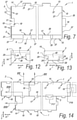
- Figure 1 shows a floor element 1 for forming the floor covering 2 of figure 2 .
- the floor element 1 is adapted to be installed on a subsurface (not shown).
- the floor element 1 is configured to be coupled to one or more adjacent floor elements 1, preferably according to a predetermined pattern, for forming the floor covering 2.
- the floor covering 2 shows an irregular offset pattern.
- the floor element 1 comprises a decorative layer 3 provided with a decor on its upper surface.
- the decorative layer 3 is rectangular and oblong in shape and is provided with a wood grain print 4 depicting wood grain lines extending globally in the longitudinal direction of the rectangular decorative layer 3.
- the print 4 is digitally printed, for example by means of ink-jet printing.
- the decorative layer 3 comprises a background coating 5 covering at least partially its upper surface and adapted to receive the print 4 on its top.
- the background coating is white, beige or brown or made of any color suitable to receive the print 4 on its top.
- the decorative layer 3 also comprises a protective coating 6 covering at least partially its upper surface and adapted to be placed above the decor, i.e. above the print 4.
- the protective coating 6 is transparent or translucent.
- the decorative layer 3 comprises a ceramic body 7, preferably made of porcelain.
- the background coating 5 and the protective coating 6 comprise glazes applied on the upper surface of the ceramic body 7.
- the floor covering 2 comprises intermediate spaces 8 that are formed between the upper edges 9 of the floor elements 1, more particularly between the edges of the decorative layer 3, in this case between the edges of the porcelain tiles.
- said intermediate space 8 is filled with a grout 10, for example an epoxy grout, so that the floor covering 2 is perfectly impermeable and thus moisture, as well as dust or dirt, cannot pass from the upper surface of the floor covering 2 to the subsurface or vice versa.
- the floor element 1 comprises a reinforcing layer 11 disposed beneath the decorative layer 3, preferably directly bonded to the lower surface 12 of the decorative layer 3, e.g. to the lower surface of the ceramic body 7, for example by means of a glue.
- the reinforcing layer 11 is a metal plate, preferably made of steel, and is configured to establish a compressive state in the decorative layer 3.
- the metal plate defining the reinforcing layer 11 has a coefficient of thermal expansion higher than the coefficient of thermal expansion of the decorative layer 3, for example of the ceramic body 7.
- the reinforcing layer 11 is heated to a stretched state, then the reinforcing layer 11 is bonded to the decorative layer 3 while it is still in the stretched state and subsequently it is cooled down to retract and put the decorative layer 3 in compression.
- the decorative layer 3 has a thickness A of above 7 mm, preferably approximately 10 mm, and the reinforcing layer 11 is a steel plate having a thickness B of 0,2 mm.
- Figure 5 shows a different embodiment of the invention wherein the floor element 1 comprise an intermediate layer 13 disposed beneath the reinforcing layer 11, so that the reinforcing layer 11 is disposed between the decorative layer 3 and the intermediate layer 13.
- the intermediate layer 13 is directly bonded to the lower surface of the reinforcing layer 11, for example by means of a glue.
- the intermediate layer 13 is preferably made of the same material of the decorative layer 3, for example comprises a ceramic body, preferably made of porcelain.
- the intermediate layer 13 preferably has the same thickness as the decorative layer 3.
- the thickness A of the decorative layer 3 can be less than 7 mm, preferably about 6 mm.
- the reinforcing layer 11 comprises a fiberglass layer, for example comprises a fiberglass mat.
- the floor element 1 also comprises a support layer 14 arranged below the decorative layer 3, such that the reinforcing layer 11 is disposed in between the decorative layer 3 and the support layer 14.
- the support layer 14 has a shape basically corresponding to the decorative layer 3, e.g. rectangular and oblong in shape.
- the decorative layer 3 is mounted on the support layer 14 in such a way that, in a coupled condition of two of said floor elements 1 the intermediate distance 8 is available between the edges 9 of adjacent decorative layers 4.
- the decorative layer 3 is mounted on the support layer 14 in an offset relation in such a way that the decorative layer 3 and the support layer 14 are only partially overlapped in a plane view.
- the support layer 14 comprises a couple of consecutive edges 15 that, in a top plane view, protrude outwardly with respect to the decorative layer 3, and a couple of opposite consecutive edges 15 that are at least partially placed beneath the decorative layer 3.
- the support layer 14 is a coherent element, wherein the support layer 14 preferably covers the majority, i.e. at least 50 percent, of the lower surface 12 of said decorative layer 3. Preferably, the support layer 14 covers 80 percent or more of the lower surface 12 the decorative layer 3.
- the support layer 14 is made of a polymeric material, preferably a thermoplastic polymeric material, preferably with a glass transition temperature (Tg) below 100°C, for example of PVC (polyvinyl chloride).
- Tg glass transition temperature
- the support layer 14 has a thickness C comprised between 2 and 7 mm, preferably about 3 mm or less.
- the edges 15 of the decorative layer 10 are provided with coupling elements 16, 17, 31, 35 configured to realize a mechanical coupling with coupling elements 16, 17, 31, 35 of an adjacent floor element 1.
- the coupling elements 16, 17, 31, 35 preferably comprise at least a male part 16 and a female part 17, wherein such male 12 and female part 17 in the connected state of two floor elements 1 have been engaged into each other.
- the male part 16 and the female part 17 are preferably at least partially formed in the support layer 14.
- the male part 16 and the female part 17 are wholly formed in said support layer 14.
- the male part 16 projects outwardly and horizontally beyond its edge 15, thereby forming a protrusion at said edge 15, while the female part 17 extends inwardly and horizontally beyond its edge 15, thereby forming a recess 18 at said edge 15.
- the male part 16 is positioned at a first edge 15 of the floor element 1 and the female part 17 is positioned at a second opposite edge 15 of the floor element 1.
- the male part 16 protrudes outwardly beyond an upper edge 9 of the decorative layer 3, and the female part 17 extends inwardly beyond an upper edge 9 of the decorative layer 3, to thereby form an undercut 19 underneath said decorative layer 3.
- said male part 16 and female part 17 can be engaged together by means of a translational motion F in a downward vertical direction of one of said adjacent floor elements 1 towards the other.
- the coupling elements 16, 17, 31, 35, in particular the male part 16 and the female part 17, are configured in such a way that the floor elements 1 can be uncoupled by means of a translational motion G in upward vertical direction.
- each edge 15 can comprise one or more male parts 16 and/or female parts 17.
- the male part 16 and/or the female parts 16 are symmetrically disposed on the same edge 15 with respect to the midpoint M of the said edge 15.
- one male part 16 and one female part 17 are provided respectively on opposite short edges 15 of the support layer 14, while a plurality of male parts 16 and of female parts 17 are provided on opposite long edges 15 of the floor element 1.
- the floor element 1 comprises male parts 16 and female parts 17 with common geometry on all its edges 15.
- Figures 12 and 13 show male parts 16 and the female parts 17 which in a top plane view are dovetail shaped such that they have a contour 20 which is tapered toward its related edge 15.
- the male part 16 and the female part 17, as seen in a top planar view show a couple of opposite sides 11, as seen in a direction X along the edge 15, which are planar and/or curved, and which are converging to each other toward the related edge 15.
- said coupling elements 16, 17, 31, 35 cooperate and form locking surfaces 21, 22, 17 limiting the mutual movement of said floor elements 1 in a vertical direction Z and/or one or more horizontal directions X, Y.
- the coupling elements 16, 17, 31, 35 cooperate and form first locking surfaces 21 adapted to limit the mutual movement of said floor elements 1 in a direction X along the coupled edges 15, as well as second locking surfaces 22 limiting the mutual movement of said floor elements 1 in a direction Y perpendicular to the coupled edges 15 and in a substantially horizontal plane.
- the first and the second locking surfaces 21, 22 are coinciding, and in this case, these first and second locking surfaces 21, 22 have a normal N with an orientation forming and angle O with the direction X of the respective edge 15, wherein this angle O is lower than 90°, preferably between 20° and 70°.
- two sets 23 of said first locking surfaces 21 and second locking surfaces 22 are formed, wherein said sets 23 limit the movement in mutually opposite horizontal directions X, Y perpendicular and along the coupled edges 15.
- said first and second locking surfaces 21, 22 are formed from the engagement of the male part 16 into the female part 17 and are both formed by surfaces 24 delimiting the male parts 16 and female parts 17 in a direction 24 along the coupled edges 15 or, in other words, said first and said second locking surfaces 21, 22 are at least formed by surfaces 24 intersecting with said coupled edges 15.
- Figure 17 also shows that, in the coupled condition, between the male part 16 and the female part 17 a gap 25 is formed to simplify the installation of the floor elements 1.
- the contact surfaces 26 along the coupled edges 15 of the floor elements 11 are reduced so that a lower force is needed to couple the floor elements 1 together.
- This arrangement is particularly useful when the decorative layer 3 comprise the ceramic body 7 because the risk of breakage of the decorative layer 3 is significantly reduced since it is not needed to provide a high force on the decorative layer 3 for coupling the floor elements 1, for example by means of a hammer or in any other way.
- the coupling elements 16, 17, 31, 35 also comprises vertical locking elements 31, 35 configured in such a way that in a coupled condition of two adjacent floor elements 1 third locking surfaces 27 are formed limiting the mutual movement of said floor elements 1 in a substantially vertical direction Z.
- said vertical locking elements 31, 35 are such that in a coupled condition of two floor elements 1 two sets 28 of third locking surfaces 27 are formed, wherein said sets 28 limit the movement in mutually opposite vertical directions Z.
- said third locking surfaces 27 are at least formed by an upward faced surface 29 positioned on one of the coupled floor elements 1 and cooperating with a downward faced surface 30 on the other coupled floor element 1.
- the third locking surfaces 27 are provided on planes P substantially horizontal or inclined with respect to the horizontal plane and forming an angle W with the horizontal plane which is lower than 90°, preferably lower than 70°, more preferably lower than 50°, for example 15° or less, or 0°.
- said vertical locking elements 31, 35 comprise a hook shaped element 31 having a first portion 32 extending form its respective edge 15 in a substantially horizontal direction and a second portion 33 extending downwardly from the first portion 32 in a substantial vertical direction.
- Said hook shaped element 31 further comprises a protruding portion 34 placed on the second portion 33 that is shaped to define at least an upward faced surface 29 which in use is adapted to cooperate with a downward faced surface 30 provided on the adjacent floor element 1 thereby forming said third locking surfaces 27.
- the downward faced surface 30 is provided in the form of a chamfered lower edge 35 of the support layer 14 so that it defines an abutment surface for the protruding portion 34 of the hook shaped element 31.
- Figure 18 shows an embodiment wherein, the portions of the edges 15 adapted to cooperate with the hook shaped element 31, i.e. the portions of the edges 15 provided with the chamfered edges 35 can be provided with a beveled upper edge 36 opposite to the chamfered edge 35 adapted to help the bending of the second portion 33 of the hook shaped element 31 during the translational downward movement F for the coupling of the floor elements 11.
- the hook shaped element 31 is provided on a first edge 15, for example a first short edge 15, on the sections 37 next to a female part 17, and on a second edge 15, for example a first long edge 15, on the male parts 13, preferably on a side of the male part 13 which is substantially parallel to the related edge 15.
- the chamfered lower edges 35 defining the downward faced surface 30 is provided on the corresponding portions of the opposite edges 15, i.e. the sections 37 of the opposite short edge 15 next to the male part 16, and on the female parts 17 of the opposite long edge 15, preferably on the bottom 38 or innermost part of the recess 18 formed by the female parts 17.
- the hook shaped element 31 disposed on the sections 37 free from the male part 16 or the female part 17, in this example the hook shaped element 31 on the short edge 15, is placed beneath the decorative layer 3 so that a C-shaped recess 39 is formed between the protruding portion 34 of the hook shaped element 31 and the decorative layer 3.
- the third locking surfaces 27 are also formed by a top surface 40 of said male part 16 and the downward faced surface 30 defined by the undercut 19 formed by said female part 17.
- a first set 28 of third locking surfaces 27 is formed by the upward faced surface 29 provided on the protruding portion 34 of the hook shaped element 31 which cooperates with the downward faced surface 30 defined by the chamfered edge 35 provided on the adjacent floor element 1, while a second set 28 of third locking surfaces 27 is formed by the upward faced surface 29 defined by the upper surface 41 of the support layer 14 and the downward faced surface 30 defined by the bottom surface 12 of the decorative layer 3.
- the section 37 of a first floor element 1, provided with the chamfered edge 35 is at least partially inserted in the C-shaped recess 39 formed between the protruding portion 34 and the upper decorative layer 3.
- the two sets 28 of third locking surfaces 27 are disposed in succession one after the other in a substantially vertical direction Z, or in other words, they are present in one and the same cross-section taken along the respective edge 15.
- Figure 16 shows a cross section of figure 14 wherein only one set 28 of third locking surfaces 27 is formed limiting the movement in only one vertical direction Z.
- Said set 28 of third locking surfaces 27 is at least formed by the top surface 40 of the male part 16 and the downward faced surface 30 defined by the undercut 19 formed by the female part 17 of the adjacent floor element 1, i.e. the bottom surface 12 of the decorative layer 3 delimiting said undercut 19 in an upward direction Z.
- Figures from 19 to 23 show different examples of the male parts 16 and the female parts 17.
- Figure 19 shows an alternative embodiment wherein the male part 16 and the female part 17 are T-shaped, in a top planar view, with the head 42 of the T forming the male part 16 engaging behind portions 43 of the female part 17 so that the second locking surfaces 22 are at least formed by surfaces 44 delimiting the male part 16 and female part 17 in a direction Y perpendicular the coupled edges 15.
- the first locking surfaces 21 and the second locking surfaces 22 are distinct.
- Figure 20 shows an example wherein the male part 16 and the female part 17 have curved contours 45 in a top planar view, so that the two sets of first and second locking surfaces 21, 22 are formed by a continuously curved surface 45 in a top planar view.
- Figure 21 shows an example wherein the male part 16 and the female part 17 comprise two opposite curved surfaces 46 so that each curved surface 46 forms one set 28 of first and second locking surfaces 14, 15.
- Figure 22 shows an example wherein the male part 16 and the female part 17 have contours 20 comprising a curved side 47 and an opposite straight side 48.
- Figures 23 and 24 show alternative examples wherein the male part 16 and the female part 17 have contours 20 formed by straight sides 49.
- Figures 25 and from 26 to 28 shows different embodiments wherein the first locking surfaces 21 and the second locking surfaces 22 are formed on first resilient arms 50 adapted to be bent when the floor elements 1 are coupled together thereby exerting a thrust reaction which forces the floor elements 1 towards each other so that the relative movement of the floor elements 1 in a horizontal direction X, Y is limited.
- the first resilient arms 50 are disposed in a direction which is substantially horizontal and are adapted to bent in a direction R substantially horizontal.
- the first resilient arms 50 can delimit the male part 16 and/or the female part 17 in a direction along the coupled edges 15.
- figures 25, 26 and 27 show embodiments wherein the female part 17 comprises two firsts resilient arms 50 limiting the recess 18 formed by the female part 17 itself in both the opposite directions X along the respective edge 15.
- Figure 28 shows an alternative embodiment wherein the male part 16 comprises two opposites first resilient arms 50.
- the vertical locking elements 31, 35 in particular the hook shaped elements 31 and the chamfered edge 35 can be provided also on the variants of male parts 16 and female parts 17 shown in figures from 19 to 24 and from 25 to 28, for example the hook shaped element 31 can be provided on the head 42 of the T-shaped male part 16 of figure 18 .
- the third locking surfaces 27 comprise portions 29 provided on second resilient arms 51 disposed in a direction Z which is substantially vertical and are adapted to bent in a direction S substantially horizontal.
- the hook shaped element 31, and more in detail the second portion 33 of the hook shaped element 31, substantially define the second resilient arm 51.
- Figures from 29 to 31 shows an alternative embodiment of the invention wherein the male parts 16 and the female parts 17 are shaped in the form of a tongue 52 and a groove 53 that substantially run through the whole length of the related edge 15.
- Figure 31 shows that in a coupled condition of two adjacent floor elements 1 according to this alternative embodiment, only the second and the third locking surfaces 22, 27 are formed.
- the second locking surfaces 22 are at least formed by surfaces 54 delimiting the tongue 21 and the groove 22 in a direction perpendicular the coupled edges 15.
- the second locking surfaces 22 are formed by a downwardly projecting protrusion 55 of the tongue 52 and from a cooperating therewith recess 56 of the groove 53.
- two sets 28 of third locking surfaces 27 limiting the movement in mutually opposite vertical direction Z are disposed in succession one after the other in a substantially vertical direction Z.
- the two sets 28 of third locking surfaces 27 are formed respectively by a bottom surface 57 of the tongue 52 cooperating with an upward faced surface 58 of the groove 53, and by an upper surface 59 of the tongue 52 and a cooperating therewith downward faced surface 60 of the groove 53.
- the support layer 14 is preferably made of fiber cement, and has a thickness C of 6 mm.
Description
- The present invention relates to a floor element for forming a floor covering and a floor covering.
- More particularly, the invention is related to a floor element for forming a floor covering, wherein this floor element comprises a decorative layer made of a brittle material such as natural stone, glass or sintered ceramic materials like porcelain, earthenware or the like. The decorative layer can for example be a ceramic tile.
- Traditionally, ceramic tiles are installed by laying them side by side on a surface such as a floor or wall. Typically, an adhesive compound is used to attach the tiles to the surface. Seams between the tiles are grouted. In this way, the tiles are bonded to a rigid surface, for example a concrete subfloor, thereby improving their impact strength. The bound with the subfloor, and thus also with the structure of the dwelling, also leads to a high attenuation of walking sounds, both in the room where the floor is installed, and in quarters below the respective room. The tiled surface is water impervious and hygienic, since it can be cleaned in a very wet manner. The step of installing the tiles with an adhesive is, however, labor intensive and represents a significant portion of the labor involved in a typical floor covering installation. Moreover, this installing technique requires a high professional competence in order to obtain a well levelled floor covering. Thus, due to the time and labor involved in the installation, it is typically quite costly to have tiles professionally installed.
- To substitute an existing floor covering made of tiles, it is often necessary to break the tiles, regenerate the surface by removing the residues of adhesive and then install a new floor covering. Thus, the demolition of a floor covering made of tiles is a labor and time consuming operation. If the aim of the restoration is to substitute only one or a few damaged tiles, this operation becomes also difficult, since the substitution of one tile preferably does not damage the adjacent tiles.
- In recent years, manufacturers have attempted to produce do-it-yourself tiling solutions that are easier to install. Some examples of these attempts are shown in
WO 2004/097141 ,JP 2012 026260 EP 2 369 090WO 2008/097860 . The floor elements disclosed in those documents can be laid on a surface and mechanically coupled together to form a floor covering without the use of an adhesive, thereby reducing the labor and time of the installing phase. Such kind of floor covering is known as a floating floor covering. In particular, in these documents, a ceramic tile or natural stone slab is fixed to a support layer that comprises coupling elements configured to realize a coupling with coupling elements of an adjacent floor element, thereby forming a floor covering. - On the other hand, since such floor elements are not bonded to a common rigid surface, the impact strength and, consequently, the fatigue strength is significantly reduced. The floating installation may also give rise to louder walking noise. The joints between the tiles of
WO 2008/097860 may be prone to water penetration especially upon wet cleaning. According to some embodiments ofWO 2004/097141 , grout may be applied in the joints available between adjacent floor elements, which may lead to water imperviousness of the respective joint. - To improve the impact resistance of ceramic tiles,
US 2014/349084 suggests a tile with a composite build-up. In this composite tile, a reinforcing layer is arranged in between two ceramic layers or in between a ceramic layer and a polymer laminate. As example of a reinforcing layer, a fiberglass layer is mentioned. The installation of this tile is, however, still cumbersome. A bonding with an underlying subfloor is required, for example via a bottom layer with pressure sensitive adhesive or tack fast loop fabric so that the tile is substantially made solid with the subfloor for improving the impact strength. Moreover, a precise positioning of the tile is difficult. -
WO 2010/072704 proposes a different type of reinforcing layer, namely a steel plate. This steel plate is adhered to the back surface of the ceramic tile or slab. Also here, the installation is, however, difficult. The installation is done by simply resting the tiles on a subfloor, so that a precise positioning of the tile is difficult and the floor covering results in a not well levelled surface and in a noisy and permeable floor covering. -
WO 2009/142365 andKR 2011 0064350 - Thereto, the present invention relates to a floor element according to
claim 1. - The inventors have found that, thanks to this solution, the impact resistance of the floor element, more particularly of the decorative layer of ceramic, is highly increased, so that, even with the mechanical locking between such floor elements, the impact strength achieves or even exceeds the impact strength of the traditional elements installed by means of adhesives. In fact, the reinforcing layer substantially improves the rigidity of the decorative layer, thereby defining a hinder to the propagation of cracks in the decorative layer itself. Furthermore, in case of superficial cracks of the decorative layer, the reinforcing layer keeps the decorative layer itself coherent, and preferably compacted, thereby disguising the visual appearance of the superficial cracks.
- Impact strength for flooring can be determined by means of a steel ball impact test. According to this test the impact strength is measured by dropping a steel ball on the floor element from a certain height, if the floor element does not break the height is increased until a height is reached where the steel ball breaks the floor element. The steel ball has a weight of 225,5 grams and a diameter of 38,1 mm (1,5 inches). The impact strength is expressed in terms of the maximum attainable height from which the steel ball, when dropped on the floor element does not break the floor element. The higher the drop height, the higher is the impact strength. The impact strength can be expressed in Newton-meter (Nm), i.e. the energy of the steel ball when hitting the surface of the floor element. The inventors have found that traditional floorings, for example floorings made of porcelain floor elements with a thickness of approximately 10 mm, directly glued to a subfloor, usually show impact strength comprised between 1,68 Nm and 2,25 Nm (corresponding to a ball falling from a height comprised between 762 and 1016 mm) whereas known floating floors show an impact strength usually lower than 1,12 Nm (corresponding to a ball falling from a height lower than 508 mm). The inventors have found that, thanks to this solution, an impact strength of above 1,91 Nm (corresponding to a fall of the steel ball from a height of above 863 mm) can be achieved.
- Fatigue strength for flooring is determined by means of the so called Robinson Test according to ASTM C627. According to this test a three-wheel cart rotates about its center on top of a sample section of a tiles floor. Above each wheel is a rod along which weights can be stacked. A power motor drives the assembly and the cart rotates at a rate of 15 revolutions per minute. The test is run according to a loading schedule with 14 different cycles. For each cycle, the schedule specifies a type of wheel to be used (soft rubber, hard rubber, or steel), the amount of weight to be stacked above each wheel, and the total number of cart revolutions to be executed. After the completion of each cycle, the sample floor section is visually examined. The test result qualifies the floor according to the number of cycles passed without failure and indicates the following service level to which the floor is destined:
-
Sample completing cycles 1 through 3 without failure: "Residential" rating; -
Samples completing cycles 1 through 6: "Light" commercial rating; -
Samples completing cycles 1 through 10: "Moderate" commercial rating; -
Samples completing cycles 1 through 12: "Heavy" commercial rating; - Samples completing all 14 cycles without failure are assigned in "Extra heavy" commercial rating.
- The inventors have found that thank to the use of a reinforcing layer, the Robinson Test can result in passing 6 cycles (Light Commercial) as minimum.
- In accordance with the most preferred embodiment of the invention, the decorative layer comprises a ceramic body, for example made of porcelain, stoneware, earthenware, or other sintered ceramic powders. Preferably, the decorative layer is a ceramic tile or slab. With "ceramic tile" an element is meant with a body consisting of baked minerals, such as clay, and preferably with a fired decorative top surface, preferably on the basis of a glaze.
- It is noted, however, that this first aspect can be advantageously applied with decorative layers being made of any kind of brittle material, such as natural stone, concrete, glass or glass-ceramic material. With brittle material is intended a material that breaks without significant plastic deformation. In particular, for the scope of said patent application, with the term brittle material is intended a material that of its own (if not bonded to a support layer and without reinforcing element) has an impact strength lower than 1,68 (corresponding to a ball falling from a height lower than 762 mm) according to the ball impact test.
- The decor of the decorative layer can be provided with a variety of textures, designs and colors. In a preferred embodiment, the decor simulates a natural product, such as natural stone or wood. Preferably, the decor is at least partially formed by a print. The print is preferably realized by means of digital printing, such as inkjet printing, although screen printing, rotogravure, flexography or off-set printing is not excluded. According to a variant, the decor is at least partially formed by uniformly colored base material or by a mix of colored base materials.
- The decorative layer can comprise a background coating covering at least partially its upper surface and adapted to receive the decor on its top, for example adapted to receive the print on its top. The background coating can be white, beige, brown or of any color suitable to receive a decor on its top. In the case that the decorative layer is made of a ceramic material, the background layer preferably comprises at least a glaze covering the upper surface of the ceramic body.
- The decorative layer can also comprise a protective coating covering at least partially its upper surface and adapted to be placed above the decor. The protective coating can be transparent or translucent. It is clear that the protective coating can be used in combination with the background coating. In the case that the decorative layer is made of a ceramic material, the protective layer preferably is a glaze.
- Preferably, the decorative layer has a thickness comprised between 4 and 15 mm, for example 6 mm, preferably above 7 mm, for example 10 mm. The inventors have found that by adding a reinforcing layer a satisfying fatigue behavior can be achieved for a relatively thin decorative layer.
- It is clear that the decorative layer can be made of any shape, for example a squared, rectangular or hexagonal shape. In the preferred embodiment, the floor elements are rectangular and oblong in shape, and are preferably provided with a wood grain print depicting wood grain lines extending globally in the longitudinal direction of the rectangular decorative layer. Preferably, the support layer has a shape basically corresponding to the decorative layer, however, preferably, with one or more portions extending beyond the decorative layer and one or more recesses extending underneath the decorative layer. The support layer preferably is a coherent element, wherein the support layer preferably covers the majority, i.e. at least 50 percent, of the lower surface of said decorative layer. Preferably the support layer covers 80 percent or more of the lower surface of the decorative layer. According to a variant, the support layer comprises a plurality of separate adjacent support layer portions, in which case said plurality of support layer portions preferably covers at least 50 percent of the lower surface, or even 80 percent or more thereof.
- According to the first aspect of the invention, the floor element comprises a reinforcing layer arranged in between the decorative layer and the support layer. Such reinforcing layer can be realized in accordance with several possibilities, of which here below two preferred possibilities are described.
- According to a first possibility, the reinforcing layer comprises a fiberglass layer, such as a fiberglass mat, a fiberglass fleece or a fiberglass cloth. In combination or as an alternative to glass fibers, the reinforcing layer can comprise carbon fibers, polymeric fibers, for example aramid or polyamide fibers, or ceramic fibers, for example boron or silicate fibers. The reinforcing layer can comprise woven or non-woven fibers, for example with fibers disposed at different orientations. The reinforcing layer can also comprise a plurality of fiber layers overlaying each other, for example with fibers disposed at different orientations in each layer. A fiber layer provides a rigid reinforcing layer, thereby increasing the rigidity of the decorative layer to define a hindrance to the propagation of cracks in the decorative layer itself.
- According to a second possibility, the reinforcing layer comprises a metal plate, for example a steel plate. Preferably, the metal plate is configured to establish a compressive state in the decorative layer. In this way, since the decorative layer is in a compressive state, the impact resistance is strongly improved, because the compression obstacles the propagation of cracks and helps in disguising the visual effect of superficial cracks. To achieve this goal, the metal plate is first stretched, for example by means of a mechanical or thermal stretching, and then is bonded to the decorative layer while the metal plate is in the stretched state. Subsequently, the stretch is released, by interrupting the mechanical solicitation or by cooling the metal plate itself, thereby establishing a compressive state in the decorative layer.
- According to a preferred embodiment, the metal plate has a coefficient of thermal expansion higher than the coefficient of thermal expansion of the decorative layer. Thanks to this solution, the reinforcing layer is heated to a stretched state, then the reinforcing layer is bonded to the decorative layer while it is still in the stretched state and subsequently it is cooled down to retract and put the decorative layer in compression.
- In a preferred embodiment, the metal plate is a steel plate, preferably having a thickness between 0,1 and 1 mm, for example 0,2 mm.
- The inventors have found that embodiments in accordance with said second possibility may achieve an impact resistance of approximately 3,09 Nm (corresponding to a ball falling from an height of 1397 mm) and a Robinson Test result of Extra Heavy Commercial. Thank to this solution, it is possible to use ceramic tiles having standard thickness for a floating floor covering.
- The inventors have, rather surprisingly, found that, with such metal plate, good results can be obtained even with a relatively thin decorative layer of ceramic. For example, the decorative layer can be less than 15mm, more preferably less than 12 mm. Preferably, the thickness of the decorative layer is, however, at least 7 mm. With such thickness values, excellent impact resistance can be obtained, even with the mechanical connection between the floor elements. For example, impact resistance of approximately 3,09 Nm (corresponding to a ball falling from an height of 1397 mm) and a Robinson Test result of Extra Heavy Commercial can be achieved. An advantage is also that, for the decorative layer, a ceramic tile with standard thickness can be used, e.g. a ceramic tile with a thickness of 10 mm. Moreover, no additional layers are needed for achieving a good impact resistance. For example, no intermediate layer, with the exception of nonstructural layers such as adhesive layers, between the decorative layer and the metal plate, and/or between the metal plate and the support layer, is needed. Hence, the total thickness of the floor element can be limited. In a preferred construction, the decorative layer is directly bonded to the metal plate and the metal plate directly bonded to the support layer.
- In general, the reinforcing layer is preferably made of a material showing a Young's modulus higher than the Young's modulus of the decorative layer, for example two or three times the Young's modulus of the decorative layer. In this way, a reinforcing layer is provided that increases the rigidity of the decorative layer to define a hindrance to the propagation of cracks.
- Preferably, the reinforcing layer is bonded to the decorative layer and/or to the support layer by means of an adhesive layer, for example a glue. In a preferred case, the reinforcing layer is at least directly bonded to the lower surface of the decorative layer. It is noted that the reinforcing layer is not necessarily disposed directly between the decorative layer and the support layer. In other words, together with the reinforcing layer, one or more other intermediate layers can be provided in between the decorative layer and the reinforcing layer and/or in between the reinforcing layer and the support layer.
- For example, the floor element may comprise an intermediate layer disposed in between the reinforcing layer and the support layer or in between the reinforcing layer and the decorative layer. In a preferred case, this intermediate layer is disposed in between the reinforcing layer and the support layer. The inventors have found that by providing such intermediate layer in combination with a reinforcing layer, the strengthening effect is enhanced, so that the impact and the fatigue strength of the floor element are further improved. The inventors have also found that the use of an intermediate layer in combination with a reinforcing layer permits reducing the thickness of the decorative layer
- For example, it has surprisingly been found that the impact resistance of a thin ceramic tile, such as a tile with a thickness of 6 mm or less, can be remarkedly enhanced by laminating to the back surface of said tile a reinforcing layer, such as a fiberglass layer, and to this reinforcing layer an intermediate layer, such as a second tile preferably having the same thickness or about the same thickness as the decorative layer.
- The intermediate layer can be made of the same or similar material of the decorative layer. For example, in a preferred embodiment, the intermediate layer is made of a ceramic body or another brittle material, such as one of the materials listed at the outset of the present application. The inventors have found that an intermediate layer made of the same material as the decorative layer is sufficient to exceed the standard strength of a traditional floor.
- Possibly, the intermediate layer is made of a lower quality material than the decorative layer, for example it is essentially made of a non-decorated ceramic plate, a nonsmoothed natural stone, a recycled ceramic plate, or a ceramic plate made starting from a mixture of raw materials comprising a high amount of waste or scrap material, for example household, demolition, industrial or waste.
- Preferably, the intermediate layer has the same thickness as the decorative layer. It is clear that the intermediate layer can show a thickness bigger or smaller than the thickness of the decorative layer.
- Preferably, the reinforcing layer and, where available, the intermediate layer has substantially or completely the same shape and horizontal dimension as the decorative layer. Moreover, the decorative layer is overlapped to the reinforcing layer and, where available, the intermediate layer in order to cover and hide the reinforcing layer.
- The intermediate layer can be bonded to the reinforcing layer, and to the support layer, or to the decorative layer by means of adhesive layers, for example a glue.
- The glue used for bonding together the various elements of the floor element can be an epoxy glue, a hotmelt glue or a polyurethane based glue.
- The inventors have found that the use of the intermediate layer is especially advantageous if a fiberglass layer is applied as reinforcing layer. If the fiberglass layer is disposed in between two ceramic tiles, very good results can be obtained in terms of impact resistance of the mechanically connected floor elements. The inventors have found that with that solution an impact resistance of 3,37 Nm (corresponding to a ball from 1524 mm) can be achieved. This is the case also when decorative layer and the intermediate layer both have a thickness of 6 mm or less. Hence, thanks to this solution it is possible to use thin ceramic tiles for floating floor covering while having extremely high values of impact resistance and/or of fatigue strength. In a preferred construction, the fiberglass layer is directly bonded to the ceramic decorative layer and to the ceramic intermediate layer, and the intermediate layer is directly bonded to the support layer. The direct bonding can take place by means of an adhesive or glue.
- According to a preferred embodiment of the invention, the support layer is made of a material that is different from the material of the decorative layer. More in particular, the support layer is preferably made of a material adapted to be provided with coupling elements and/or made of a waterproof material and/or made of a compressible material.
- According to the invention, the support layer is made of fiber cement. The inventors have found that thanks to this solution the floor element has a high impact and fatigue strength in combination with high thermal stability so that the floor element does not significantly expand or contract when exposed to a temperature variation.
- Furthermore, the support layer preferably has a thickness comprised between 2 and 7 mm, preferably 6 mm, more preferably about 3 or less.
- An alternative embodiment provides for a support layer made of fiber cement and having a thickness of 6 mm thereby providing a very good thermal stability.
- Thus, the thickness of the floor element is lower than 20 mm, preferably 18 mm or lower, more preferably 13 mm or lower. In this way, the thickness of the resulting floor element is relatively thin, so that the impact of the floor in the environment is reduced, especially in case of restoration of existing flooring. Moreover, in this way, the weight of the floor element is limited so that the packaging, the transport and the installation are made easier.
- As mentioned before, the support layer comprises edges with coupling elements. The coupling elements are configured to realize a mechanical coupling with coupling elements of an adjacent floor element. Under a "mechanical coupling", a coupling is to be understood that allows adjacent floor elements to be coupled without the need for glue or the like. A mechanical coupling may be attained by means of profiled edge contours comprising coupling elements, mostly a male and a female part, that fit into each other.
- The coupling elements preferably comprise at least a male part and at least a female part, wherein such male and female part in the connected state of two such floor elements have been engaged into each other. The male and the female parts are preferably at least partially formed in the support layer. For example, the male and/or female part may be wholly formed in said support layer.
- Preferably, at least one male part is positioned at a first edge of the floor element and at least one female part is positioned at a second opposite edge of the floor element. Preferably, the male part projects outwardly in a horizontal direction from its respective edge, thereby forming a protrusion at said edge, while the female part preferably extends inwardly in a horizontal direction from its respective edge, thereby forming a recess at said edge. Said male and female part in a connected state of two similar floor elements engage into each other to create a mechanical coupling between the respective edges, preferably resulting in a locking between said edges at least in all horizontal directions in the plane of installed floor elements. According to a special embodiment the engagement of male and female part results in a locking between the respective edges at least in the vertical direction perpendicular to the plane of installed floor elements.
- The coupling elements are preferably configured to allow realizing a coupling by means of a movement of one floor element with respect to another adjacent floor element. Such movement may be a translational motion in a downward, e.g. vertical, direction, a translational motion in a horizontal direction, e.g. perpendicular to the edges or an angling motion around a horizontal axis parallel to the edges. It is clear that the respective motion then preferably results in the aforementioned male and female parts of adjacent floor elements becoming mutually engaged.
- Preferably, the coupling elements are configured in such a way that the floor elements can be uncoupled by means of a translational motion in an upward, e.g. vertical, direction.
- As used herein, the terms "horizontal" and "vertical" are basically expressed regarding a floor covering installed on a surface which is considered to be horizontal in its general meaning. Thus, when used regarding a single floor element which is a substantially flat element provided with a main plane, the terms "horizontal" and "vertical" are to be considered respectively equivalent to the terms "parallel with respect to the main plane of the floor element/installed floor elements" and "perpendicular with respect to the main plane of the floor element/installed floor elements".
- In general, the coupling elements may be construed in several ways. Here below, two general possibilities for their construction are described, without excluding any further possibilities also falling under the scope of the present invention.
- In a first general possibility for the construction of the coupling elements, the male part and the female part extend over a limited length portion of the related edge, wherein such limited length is smaller than the whole length of the related edge itself, preferably smaller than half the length of the related edge. In accordance with this possibility, the edges preferably comprise sections free from said male part and said female parts. As an alternative, male and female parts may alternate along the edge. Preferably, at said edge, the decorative layer is at least supported by the support layer over 30% of the length of the related edge. In this way, the risk of failure of the brittle material in the packaging or upon installation is reduced. According to the present first possibility, each edge can comprise one or more male part and/or one or more female parts. Preferably the male and female parts are disposed along such edge such that, upon choice of the installer, the floor elements can be installed in several patterns, for example a regular flanked pattern, a herringbone pattern and/or an offset pattern, for example a half-half offset pattern or a one third offset pattern. Preferably, the male part and/or the female parts are symmetrically, either mirror symmetrically or parallel symmetrically, disposed on the same edge with respect to the midpoint of the said edge. In the case of installation in a half-half pattern, the male and/or female parts preferably are disposed in the same manner along both halves of the respective edge. In the case of installation in a one third offset pattern, the male and/or female parts preferably are disposed in the same manner along all three thirds of the respective edge. As mentioned above, in an alternative embodiment, the male and female parts alternate each other on a same edge.
- Geometries for coupling parts in accordance with the first possibility include cooperating male and female parts which in a top plan view are dovetail-shaped or male and female parts which in a top plan view resemble the connections of jigsaw puzzles.
- In a second general possibility for the construction of the coupling parts, the male part and female part can be disposed substantially along the whole length of the related edge, for example, substantially defining the related edge. For example, according to this embodiment, the male and the female parts, can be basically shaped as a tongue and a groove that substantially run through the whole length of the related mutually opposite edges.
- Preferably, the floor element comprises male parts and/or female parts with common geometry on all its edges, thereby allowing several installing patterns. It is clear that, according to different embodiments of the invention, the floor element can comprise male parts and/or female parts of differing geometries on the same edges or on different edges. For example, the floor element can comprise male parts and/or female parts of different shape or of different dimension on different edges. For example, a rectangular floor element can comprise first male parts and/or female parts of a first shape on the long edges and second male parts and/or female parts of a second shape on the short edges. Thank to this solution, the floor element can be installed only according to specific selected patterns, thereby obtaining specific selected visual effects of the floor, and minimizing the occurrence of installation mistakes.
- In a coupled condition of two of said adjacent floor elements, said coupling elements cooperate and preferably form locking surfaces limiting the mutual movement of said floor elements in a vertical and/or one or more horizontal directions.
- For example, said locking surfaces can comprise first locking surfaces adapted to limit the mutual movement of said floor elements along the coupled edges. Thanks to this solution, the floor elements cannot slide one relative to the other, once they are coupled so that the installing of the floor covering is made easier. This is especially so when a pattern in the floor covering, such as a checkboard pattern or a half-half offset pattern is desired. The prevention or limiting of mutual movement of floor elements alongside each other at a first pair of edges is also of interest in the installed floor covering, since this may aid in maintaining the connection between a second pair of edges of adjacent floor elements, e.g. perpendicular thereto.
- According to a preferred embodiment, said first locking surfaces are formed from the engagement of the male part into the female part. According to this example, said first locking surfaces are preferably at least formed by surfaces delimiting the male and female parts in a horizontal direction along the coupled edges or, in other words, said first locking surfaces are preferably at least formed such that they or their extensions are intersecting with said coupled edges.
- Preferably, in a coupled condition of two adjacent floor elements, second locking surfaces are formed limiting the mutual movement of said floor elements in a direction perpendicular to the coupled edges and in a substantially horizontal plane. Preferably, the second locking surfaces are formed from the engagement of the male part into the female part. Preferably, the second locking surfaces are at least formed by surfaces delimiting the male and female parts in a horizontal direction perpendicular to the respective edge Such second locking surfaces may be formed according to a number of possibilities, of which, here below, three possibilities are described in more detail.
- In a first possibility for the construction of said second locking surfaces, the second locking surfaces are coinciding with said first locking surfaces, in which case these surfaces have a normal with an orientation forming an angle with the direction of the respective edge, wherein this angle is lower than 90°, preferably between 20 and 70°. In particular, in accordance with this preferred embodiment of the invention, the first and the second locking surfaces are formed from the engagement of the male part into the female part and are both formed by surfaces delimiting the male part and female parts in a direction along the coupled edges or, in other words, said first and said second locking surfaces are at least formed by surfaces, which by themselves or their extensions intersect with said coupled edges. According to this preferred example, the male part and the female part, seen in a top planar view, may have a contour which is tapered toward its related edge. For example, the male part and the female part, as seen in a top planar view, can be dovetail shaped or show a couple of opposite sides, as seen in a direction along the edge, which are planar and/or curved, and which are converging to each other toward the related edge. In this way, in a coupled condition of the male part with the female part, said first and second locking surfaces are formed on said tapering or converging sides. It is clear that in according with such embodiment, the male part may be shaped as a protrusion on the related edge with is dovetail shaped, and the female part may be shaped as a matching recess on the opposite edge of the floor element.
- In a second possibility for the construction of said second locking surfaces, the second locking surfaces are distinct or separate from said first locking surfaces. In accordance with this second possibility, the second locking surfaces can be at least formed by surfaces delimiting the male and female parts in a direction substantially perpendicular to the coupled edges. For example, according to said embodiment, the male and the female part, in a top planar view, can be T-shaped, with the head of the T forming the male part and engaging behind portions of the female part. According to another embodiment, the male part may be provided with one or more barbs engaging behind portions of the female part. Alternatively, in accordance with a third possibility the second locking surfaces can be formed by a vertically protruding part and a vertically recessed part engaging behind each other. For example, in the case the coupling parts are basically shaped as a tongue and a groove, the tongue may be provided with a downwardly directed protrusion and the groove may be provided with a cooperating therewith recess.
- The coupling elements may be configured in such a way that, in a coupled condition of two adjacent floor elements, only one set of said first and/or second locking surfaces is formed limiting the mutual movement of said floor elements in one substantially horizontal direction perpendicular and/or along the coupled edges, although it is preferred that in said coupled condition at least two sets of said first locking surfaces and/or second locking surfaces are formed wherein said sets limit the movement in mutually opposite horizontal directions perpendicular and/or along the coupled edges. Thanks to this solution, the coupling elements are easily and conveniently shaped to limit the movement in substantially all the horizontal directions thereby providing a strong locking between the tiles.
- Furthermore, the coupling elements preferably comprise vertical locking elements configured in such a way that in a coupled condition of two adjacent floor elements third locking surfaces are formed limiting the mutual movement of said floor elements in a substantially vertical direction. Thanks to this solution, the floor elements can fluently be installed without the occurrence of unacceptable height differences between adjacent floor elements. Moreover, the floor elements are solidly coupled to each other to improve the fatigue behavior of the floor covering. Further, by limiting relative movement of the floor element, it is possible to reduce the step noise effect, i.e. reduce the noise generated at every step.
- Preferably, the vertical locking elements are provided along substantially the whole length of the coupled edges, although they can extend over limited portions of said coupled edges only, e.g. only there where a male or female part is present.
- In particular, said third locking surfaces can be at least formed by an upwardly facing surface positioned on one of the coupled floor elements and, a cooperating therewith, downwardly facing surface on the other coupled floor element. In other words, the third locking surfaces are provided on surfaces or planes substantially horizontal or inclined with respect to the horizontal plane and forming an angle with the horizontal plane which is lower than 90°, preferably lower than 70°, more preferably lower than 50°, for example 15° or less, or 0°, in other words horizontal.
- Third locking surfaces may be construed in accordance with several different possibilities, of which here below three are shortly described.
- According to a first possibility, said vertical locking elements comprise a hook-shaped element having a first portion extending from its respective edge in a substantially horizontal direction and a second portion extending downwardly from the first portion in a substantial vertical direction. Said hook-shaped element further comprises a protruding portion placed on the second portion that is shaped to define at least an upwardly facing surface which in use is adapted to cooperate with a downwardly facing surface provided on the adjacent floor element thereby forming said third locking surfaces. For example, the downwardly facing surface is provided in the form of a chamfered lower edge of the support layer, so that it defines an abutment surface for the protruding portion of the hook shaped element.
- The hook-shaped element can be at least partially positioned on the male part, on the female part or on sections of the edge next to the male or the female part or can be provided on both the male or female part and on said sections next to the male or the female part. In a preferred case, the hook-shaped element is provided on the sections of the edge next to the female part and on the male part, preferably on a side of the male part which is substantially parallel to the coupled edges.
- According to a second possibility, the male part protrudes outwardly beyond an upper edge of the decorative layer and the female part extends inwardly beyond an upper edge of the decorative layer to thereby form an undercut underneath said decorative layer so that the third locking surfaces may be at least formed by a top surface of said male part and an upper surface of the undercut formed by said female part, preferably a bottom surface of the decorative layer delimiting said undercut in an upward direction.
- According to a third possibility, the third locking surfaces can be at least formed by cooperating surfaces on the bottom of said male part and a cooperating therewith portion of said female part, for example an upwardly facing surface of the female part. This third possibility may be attained by means of an embodiment also showing the characteristics of the first possibility, wherein the hook shaped portion is available at the female part, and wherein the second portion of said hook forms said upwardly facing surface.
- In a preferred embodiment, said vertical locking elements are such that in a coupled condition of two floor elements two sets of third locking surfaces are formed, wherein said sets limit the movement in mutually opposite vertical directions, although it is possible that only one set of third locking surfaces is formed limiting the movement in only one vertical direction. In this way, the relative movement of the floor elements in the vertical direction is substantially prevented. Furthermore, in this way a very good vertical relation is obtained between adjacent floor elements. This solution may further lead to a reduction of the step noise. In a preferred embodiment, the two sets of third locking surfaces lie on planes that are inclined each other, preferably orthogonal.
- Two sets of third locking surfaces may be attained in a number of different manners, of which here below a first and a second possibility are described.
- In accordance with a first possibility, sets of third locking surfaces limiting the movement in mutually opposite vertical directions are sequentially, and preferably alternatingly, disposed one after the other in a direction along the coupled edges. In other words, the sets of third locking surfaces limiting the movement in mutually opposite vertical directions are available on subsequent portions of the coupled edges. It is not excluded that such portions may partially overlap. By way of example, a first edge is provided with the hook-shaped element on the male part and with the chamfered lower edge on the sections of the edge next to the male part and an opposite second edge is provided with the hook-shaped element on the sections of the edge next to the female part and the female part with the chamfered lower edge, so that in a coupled condition of said floor element with an adjacent similar floor element both the sets of third locking surfaces are formed along the same coupled edges. Thank to this solution, a very simple design of the vertical locking elements can be used thereby allowing a reduction of the thickness of the support element. The inventors have found that thanks to this solution the lower support element can show a thickness comprised between 2 and 4 mm, for example 3 mm or less.
- Preferably, a first set of third locking surfaces is positioned on a first line parallel to the coupled edges and a second set of the third locking surfaces is positioned on a second line parallel to the coupled edges, and said first and second line are distinct on the horizontal plane. For example, a first set of third locking surfaces is formed by the engagement of the male part into the female part, while the second set of third locking surfaces is formed by the engagement of the sections of the edge beside the male part with the sections of the edge next the female part. Thank to this solution the floor element can be easily manufactured to be provided with the two sets of third locking surfaces. In fact, on a single floor element the upwardly facing surface for a first set can be manufactured by means of a specific processing different from the processing for manufacturing the downwardly facing surfaces of the other set. For example, on a first edge of one floor element two different milling processes may be used, wherein these milling processes can be conducted contemporarily and acting on different parallel lines in order to manufacture the hook shaped element and the chamfered edge.
- In accordance with a second possibility, said two sets of third locking surfaces can be disposed in succession one after the other in a substantially vertical direction, or in other words, be present in one and the same cross-section taken along the respective edge. By way of example, the male part is in the form of a tongue and the female part is in the form of a groove and the two sets of third locking surfaces are at least formed respectively by a bottom surface of the tongue cooperating with an upwardly facing surface of the groove, and an upper surface of the tongue and a cooperating therewith downwardly facing surface of the groove. Alternatively, in accordance with said second possibility, the hook shaped element is disposed beneath an upper edge of the floor element so that a C-shaped recess is formed between the protruding portion of the hook shaped element and the upper edge, e.g. between the protruding portion of the hook shaped element and the lower surface of the decorative layer, so that in a coupled condition the chamfered edge of the adjacent floor element is at least partially inserted in the C-shaped recess thereby forming two sets of third locking surfaces. Particularly, a first set of third locking surfaces is formed by the protruding portion of the hook shaped element which cooperates with the chamfered edge, while a second set of third locking surfaces is formed by upper surface of the support layer provided with the chamfered edge and the upper surface of the C-shaped recess, e.g. the lower surface of the decorative layer.
- The first, second and/or third locking surfaces can comprise portions positioned on resilient arms. Such resilient arms may be adapted to be bent when the floor elements are being coupled together. In a special embodiment, the resilient arms maintain a bent position in the coupled state. In the latter case, these resilient arms may exert a reaction force which forces the floor elements towards each other so that the relative movement of the floor element in a vertical and/or in one or more horizontal directions is limited. The resilient arms can be provided either on the male part or on the female part as well as on the sections of the edge beside the male and female parts. Thanks to the resilient arms, the floor elements may be more easily coupled and/or may be solidly coupled to each other in order to improve the fatigue behavior of the whole floor. Further the resilient arms can be bent following a thermal expansion of the related coupling element of the adjacent floor element thereby allowing thermal expansion of the floor elements without affecting the stability of the floor.
- Preferably, the first and/or second locking surfaces comprise portions positioned on first resilient arms and the third locking surfaces comprise portions positioned on second resilient arms. According to an embodiment, the first resilient arms extend substantially in the horizontal plane and are adapted to bend in said horizontal plane. The first resilient arms can delimit the male part and/or the female part in a direction along the coupled edge. For example, in a preferred embodiment the female part comprises two first resilient arms delimiting the recess, which forms the actual female part itself, in both mutually opposite horizontal directions along the respective edge. Preferably, the second resilient arms extend in a direction which is substantially vertical and are adapted to bend in a direction substantially horizontal. For example, the second resilient arms at least partially delimit the said coupling elements in a direction substantially perpendicular to the related edge. In the preferred example the hook shaped element, and more in particular the second portion of the hook shaped element, substantially defines such second resilient arm. It is of course not excluded that the first and/or second locking surfaces comprise portions positioned on a same resilient arm.
- In a coupled condition of two of said floor elements preferably an intermediate distance is available between the respective upper edges of adjacent floor elements. Preferably, the decorative layer is mounted on the support layer in such a way that when the floor elements are in a coupled condition said intermediate distance is available between the edges of adjacent decorative layers, while the edges of the underlying support layer are coupled to each other by means of the available coupling elements. Thanks to this solution slight dimensional variations of the decorative layer of adjacent tiles may be tolerated. In the cases where the decorative layer is formed by one or more ceramic tiles, unrectified tiles may be selected. Even when rectified tiles would be selected, an intermediate distance of at least 1.5 millimeter is preferred. In general, with brittle decorative layers, direct contact between the edges of the decorative layers of adjacent floor elements is best to be prevented in order to minimize the risk of breaking off edge portions upon installation, or upon use of the floor covering. The prevention of direct contact between the edges of the decorative layers also prevents squeaking noises from generating when the floor is walked upon. Further some decorative layers and/or support layers may expand or contract due to thermal variation. The available intermediate distance prevents that such expansion and contraction affects the stability of the floor.
- The intermediate distance, or gap, between the decorative layers of adjacent floor elements can be further finished in several possible ways.
- According to a first possibility, said intermediate distance between the floor elements can be filled by a grout thereby providing an impermeable floor covering. Preferably a polymeric grout is used.
- In a second possibility, the decorative layer can be at least partially, preferably completely, surrounded by a gasket so that in a coupled condition of two adjacent floor elements said gasket is compressed by the decorative layer of an adjacent floor element so to form a substantially water tight connection between the floor elements.
- It is noted that the characteristic that the floor element comprises coupling elements that in a coupled condition with an adjacent floor element form first, second and third locking surfaces for limiting the relative movement of the floor element, forms an inventive idea irrespective of the presence of a decorative layer and, in particular, irrespective of the material constituting the decorative layer. Hence, the present invention, according to its second independent aspect, provides for a floor element for forming a floor covering wherein the floor elements comprise edges provided with coupling elements adapted to cooperate with coupling elements of an adjacent similar floor element in said floor covering, wherein the coupling elements comprise at least one male part and at least one female part, wherein in a coupled condition of two of said adjacent floor elements first locking surfaces are formed limiting the mutual movement of said floor elements along the coupled edges, as well as second locking surfaces limiting the mutual movement of said floor elements in a direction that is substantially horizontal and perpendicular to the coupled edge, and third locking surfaces limiting the mutual movement of said floor elements in a direction that is substantially vertical, wherein in said coupled condition two sets of third locking surfaces are formed, wherein said sets limit the movement in mutually opposite vertical directions. The inventors have found that thanks to this solution the floor elements can be solidly coupled to each other thereby forming a floor covering with good fatigue behavior. Further, by preventing relative movement of the floor elements it is possible to reduce the step noise effect, i.e. reduce the noise generated at every step.
- It is clear that the coupling elements together with the first, second and third locking surfaces are preferably formed in accordance with the preferred embodiments of the first aspect of the present invention, though without the floor elements necessarily having a decorative layer and/or support layer as described in the first aspect.
- According to a third independent aspect of the invention, it is provided a floor covering comprising a plurality of adjacent floor elements, wherein each floor element comprises a decorative layer of ceramic material and a support layer disposed below the decorative layer, wherein the floor covering comprises the combination of the following features: at least one floor element comprises a reinforcing layer in between the decorative layer and the support layer; the floor elements comprise coupling means configured to realize a coupling with coupling elements of adjacent floor elements; the floor covering comprises a grout filling an intermediate distance separating the decorative layers of the floor elements. Preferably the floor elements are separated from a subsurface, for example the subfloor, i.e. they are not bonded to the subsurface by means of adhesive or mechanical means. Thank to this solution is provided a floor covering composed of floor elements installed without using of adhesive, that shows a high satisfying impact and fatigue strength, and is totally impermeable. By means of the third aspect, the inventors have finally offered a solution to a long-felt need in the ceramic flooring world. They have provided an easy to be installed ceramic tile flooring, with a good impact strength and waterproofness. It is clear that the floor elements of the first aspect, and the preferred embodiments thereof, may be used to form a floor covering in accordance with the present third aspect.
- According to a preferred aspect of the invention the floor covering comprises an under-layer disposed beneath the floor elements that is configured to act as a moisture barrier. Thank to this solution it is possible to prevent the forming of mold underneath the floor elements. In combination or as an alternative to this solution, the under-layer can be configured to act as a noise barrier thereby reducing the noise generated by steps on the floor.
- With the intention of better showing the characteristics of the invention, in the following, as an example without any limitative character, several preferred forms of embodiments are described with reference to the accompanying drawings, wherein:
-
Figure 1 shows an embodiment of a floor element of the invention; -
Figure 2 shows a perspective view of a floor covering formed by a plurality of floor elements according toFigure 1 . -
Figure 3 on a larger scale shows a cross section along the line III-III ofFigure 1 ; -
Figure 4 on a larger scale shows a view on the area F4 indicated onFigure 3 ; -
Figure 5 in the same view asFigure 3 shows a floor element in accordance with a variant of the invention; -
Figure 6 , on a larger scale, is a top plane view of the floor element ofFigure 1 wherein the decorative layer is represented in dashed line; -
Figure 7 , on a still larger scale, is a bottom view ofFigure 6 ; - Figures from 8 to 11 show on a larger scale the cross sections respectively along the lines VIII-VIII, IX-IX, X-X and XI-XI indicated in
Figure 6 ; -
Figures 12 and 13 are on a larger scale show views on the areas respectively F12 and F13 indicated onFigure 6 ; -
Figure 14 is a top view of a floor covering assembled from the floor elements ofFigure 1 , wherein the decorative layers of the floor elements are represented in dashed lines; -
Figures 15 and16 on a larger scale show the cross sections respectively along the lines XV-XV and XVI-XVI ofFigure 14 ; -
Figure 17 on a larger scale shows a view on the area F17 indicated onFigure 14 ; -
Figure 18 on a larger scale show the cross sections along the lines XV-XV ofFigure 14 according to a variant of the invention during a coupling motion of the floor elements; - Figures from 19 to 24 on a larger scale give views on the area indicated with F19 in
-
Figure 14 , for variants of the male and the female parts; -
Figure 25 is a top view of a variant of the support layer; - Figures from 26 to 28 give views on the area indicated with F26 on
Figure 25 for variants of the male and the female parts; -
Figure 29 is a top view of a floor element according to a variant; -
Figure 30 on a larger scale shows the cross section along the line XXX-XXX ofFigure 29 ; -
Figure 31 shows a cross section of a coupled condition of two floor elements in accordance withFigure 29 ; and -
Figure 32 in a view similar to that ofFigure 17 shows a variant. -
Figure 1 shows afloor element 1 for forming the floor covering 2 offigure 2 . Thefloor element 1 is adapted to be installed on a subsurface (not shown). Thefloor element 1 is configured to be coupled to one or moreadjacent floor elements 1, preferably according to a predetermined pattern, for forming the floor covering 2. In the example shown infigure 2 , the floor covering 2 shows an irregular offset pattern. - Referring to
figures 1 ,3 and4 , thefloor element 1 comprises adecorative layer 3 provided with a decor on its upper surface. In the example shown, thedecorative layer 3 is rectangular and oblong in shape and is provided with awood grain print 4 depicting wood grain lines extending globally in the longitudinal direction of the rectangulardecorative layer 3. According to the present embodiment, theprint 4 is digitally printed, for example by means of ink-jet printing. - As visible from
figure 4 , thedecorative layer 3 comprises abackground coating 5 covering at least partially its upper surface and adapted to receive theprint 4 on its top. Preferably, the background coating is white, beige or brown or made of any color suitable to receive theprint 4 on its top. - In the example shown in
figure 4 , thedecorative layer 3 also comprises aprotective coating 6 covering at least partially its upper surface and adapted to be placed above the decor, i.e. above theprint 4. Preferably, theprotective coating 6 is transparent or translucent. - In the embodiment shown in
figures 1 ,3 and4 , thedecorative layer 3 comprises aceramic body 7, preferably made of porcelain. Thebackground coating 5 and theprotective coating 6 comprise glazes applied on the upper surface of theceramic body 7. - With reference to
figures 15 and16 , the floor covering 2 comprisesintermediate spaces 8 that are formed between theupper edges 9 of thefloor elements 1, more particularly between the edges of thedecorative layer 3, in this case between the edges of the porcelain tiles. As visible also infigure 2 , saidintermediate space 8 is filled with agrout 10, for example an epoxy grout, so that the floor covering 2 is perfectly impermeable and thus moisture, as well as dust or dirt, cannot pass from the upper surface of the floor covering 2 to the subsurface or vice versa. - As visible from
figure 3 , thefloor element 1 comprises a reinforcinglayer 11 disposed beneath thedecorative layer 3, preferably directly bonded to thelower surface 12 of thedecorative layer 3, e.g. to the lower surface of theceramic body 7, for example by means of a glue. - By way of example, in the present embodiment, the reinforcing
layer 11 is a metal plate, preferably made of steel, and is configured to establish a compressive state in thedecorative layer 3. According to this embodiment, the metal plate defining the reinforcinglayer 11 has a coefficient of thermal expansion higher than the coefficient of thermal expansion of thedecorative layer 3, for example of theceramic body 7. Preferably, the reinforcinglayer 11 is heated to a stretched state, then the reinforcinglayer 11 is bonded to thedecorative layer 3 while it is still in the stretched state and subsequently it is cooled down to retract and put thedecorative layer 3 in compression. - In the preferred embodiment shown in
figures 1 ,3 and4 , thedecorative layer 3 has a thickness A of above 7 mm, preferably approximately 10 mm, and the reinforcinglayer 11 is a steel plate having a thickness B of 0,2 mm. -
Figure 5 shows a different embodiment of the invention wherein thefloor element 1 comprise anintermediate layer 13 disposed beneath the reinforcinglayer 11, so that the reinforcinglayer 11 is disposed between thedecorative layer 3 and theintermediate layer 13. Theintermediate layer 13 is directly bonded to the lower surface of the reinforcinglayer 11, for example by means of a glue. - According to this alternative embodiment, the
intermediate layer 13 is preferably made of the same material of thedecorative layer 3, for example comprises a ceramic body, preferably made of porcelain. - The
intermediate layer 13 preferably has the same thickness as thedecorative layer 3. According to this alternative embodiment, the thickness A of thedecorative layer 3 can be less than 7 mm, preferably about 6 mm. - Preferably in the alternative embodiment of
figure 5 , the reinforcinglayer 11 comprises a fiberglass layer, for example comprises a fiberglass mat. - As visible from e.g.
figures 1 and3 thefloor element 1 also comprises asupport layer 14 arranged below thedecorative layer 3, such that the reinforcinglayer 11 is disposed in between thedecorative layer 3 and thesupport layer 14. - Referring now to
figures 6 and7 , thesupport layer 14 has a shape basically corresponding to thedecorative layer 3, e.g. rectangular and oblong in shape. In addition, thedecorative layer 3 is mounted on thesupport layer 14 in such a way that, in a coupled condition of two of saidfloor elements 1 theintermediate distance 8 is available between theedges 9 of adjacentdecorative layers 4. In the example shown infigure 6 and7 , thedecorative layer 3 is mounted on thesupport layer 14 in an offset relation in such a way that thedecorative layer 3 and thesupport layer 14 are only partially overlapped in a plane view. For example, thesupport layer 14 comprises a couple ofconsecutive edges 15 that, in a top plane view, protrude outwardly with respect to thedecorative layer 3, and a couple of oppositeconsecutive edges 15 that are at least partially placed beneath thedecorative layer 3. - In the present embodiment, the
support layer 14 is a coherent element, wherein thesupport layer 14 preferably covers the majority, i.e. at least 50 percent, of thelower surface 12 of saiddecorative layer 3. Preferably, thesupport layer 14 covers 80 percent or more of thelower surface 12 thedecorative layer 3. - In the present not claimed embodiment, the
support layer 14 is made of a polymeric material, preferably a thermoplastic polymeric material, preferably with a glass transition temperature (Tg) below 100°C, for example of PVC (polyvinyl chloride). - For example, the
support layer 14 has a thickness C comprised between 2 and 7 mm, preferably about 3 mm or less. - As clear from
figures 6 and7 , theedges 15 of thedecorative layer 10 are provided withcoupling elements coupling elements adjacent floor element 1. Thecoupling elements male part 16 and afemale part 17, wherein such male 12 andfemale part 17 in the connected state of twofloor elements 1 have been engaged into each other. Themale part 16 and thefemale part 17 are preferably at least partially formed in thesupport layer 14. For example, themale part 16 and thefemale part 17 are wholly formed in saidsupport layer 14. - The
male part 16 projects outwardly and horizontally beyond itsedge 15, thereby forming a protrusion at saidedge 15, while thefemale part 17 extends inwardly and horizontally beyond itsedge 15, thereby forming arecess 18 at saidedge 15. Preferably, themale part 16 is positioned at afirst edge 15 of thefloor element 1 and thefemale part 17 is positioned at a secondopposite edge 15 of thefloor element 1. - As clear from
figures 3 ,6 and7 , themale part 16 protrudes outwardly beyond anupper edge 9 of thedecorative layer 3, and thefemale part 17 extends inwardly beyond anupper edge 9 of thedecorative layer 3, to thereby form an undercut 19 underneath saiddecorative layer 3. - For example, in the preferred embodiment shown in
figures 6 and7 , and as indicated infigures 15 and16 , saidmale part 16 andfemale part 17 can be engaged together by means of a translational motion F in a downward vertical direction of one of saidadjacent floor elements 1 towards the other. More preferably, thecoupling elements male part 16 and thefemale part 17, are configured in such a way that thefloor elements 1 can be uncoupled by means of a translational motion G in upward vertical direction. - As shown in
figure 6 , themale part 16 and thefemale part 17 extend over a limited length portion L of therelated edge 15, wherein such limited length L is smaller than the whole length of therelated edge 15 itself. In this way, theedges 15 comprisesections 37 free from saidmale parts 16 and saidfemale parts 17. According to this embodiment, eachedge 15 can comprise one or moremale parts 16 and/orfemale parts 17. Preferably, themale part 16 and/or thefemale parts 16 are symmetrically disposed on thesame edge 15 with respect to the midpoint M of the saidedge 15. In the example offigures 6 and7 , onemale part 16 and onefemale part 17 are provided respectively on oppositeshort edges 15 of thesupport layer 14, while a plurality ofmale parts 16 and offemale parts 17 are provided on oppositelong edges 15 of thefloor element 1. - Moreover, in the preferred embodiment shown in
figures 6 and7 , thefloor element 1 comprisesmale parts 16 andfemale parts 17 with common geometry on all itsedges 15. -
Figures 12 and 13 showmale parts 16 and thefemale parts 17 which in a top plane view are dovetail shaped such that they have acontour 20 which is tapered toward itsrelated edge 15. For example, themale part 16 and thefemale part 17, as seen in a top planar view, show a couple ofopposite sides 11, as seen in a direction X along theedge 15, which are planar and/or curved, and which are converging to each other toward therelated edge 15. - In a coupled condition of two of said
adjacent floor elements 1, saidcoupling elements floor elements 1 in a vertical direction Z and/or one or more horizontal directions X, Y. - In the present embodiment, with specific reference to
figures 14 and17 , thecoupling elements floor elements 1 in a direction X along the coupled edges 15, as well as second locking surfaces 22 limiting the mutual movement of saidfloor elements 1 in a direction Y perpendicular to the coupled edges 15 and in a substantially horizontal plane. According to this embodiment, the first and the second locking surfaces 21, 22 are coinciding, and in this case, these first and second locking surfaces 21, 22 have a normal N with an orientation forming and angle O with the direction X of therespective edge 15, wherein this angle O is lower than 90°, preferably between 20° and 70°. - Preferably, in said coupled condition of the
floor elements 1, twosets 23 of said first locking surfaces 21 and second locking surfaces 22 are formed, wherein said sets 23 limit the movement in mutually opposite horizontal directions X, Y perpendicular and along the coupled edges 15. - As shown in
figure 17 , said first and second locking surfaces 21, 22 are formed from the engagement of themale part 16 into thefemale part 17 and are both formed bysurfaces 24 delimiting themale parts 16 andfemale parts 17 in adirection 24 along the coupled edges 15 or, in other words, said first and said second locking surfaces 21, 22 are at least formed bysurfaces 24 intersecting with said coupled edges 15. -
Figure 17 also shows that, in the coupled condition, between themale part 16 and the female part 17 agap 25 is formed to simplify the installation of thefloor elements 1. In fact, thanks to this arrangement the contact surfaces 26 along the coupled edges 15 of thefloor elements 11 are reduced so that a lower force is needed to couple thefloor elements 1 together. This arrangement, is particularly useful when thedecorative layer 3 comprise theceramic body 7 because the risk of breakage of thedecorative layer 3 is significantly reduced since it is not needed to provide a high force on thedecorative layer 3 for coupling thefloor elements 1, for example by means of a hammer or in any other way. - With specific reference to figures from 8 to 11, 15 and 16, the
coupling elements vertical locking elements adjacent floor elements 1 third locking surfaces 27 are formed limiting the mutual movement of saidfloor elements 1 in a substantially vertical direction Z. Preferably, saidvertical locking elements floor elements 1 twosets 28 of third locking surfaces 27 are formed, wherein said sets 28 limit the movement in mutually opposite vertical directions Z. - In particular, said third locking surfaces 27 are at least formed by an upward
faced surface 29 positioned on one of the coupledfloor elements 1 and cooperating with a downward facedsurface 30 on the other coupledfloor element 1. In other words, the third locking surfaces 27 are provided on planes P substantially horizontal or inclined with respect to the horizontal plane and forming an angle W with the horizontal plane which is lower than 90°, preferably lower than 70°, more preferably lower than 50°, for example 15° or less, or 0°. - In the present embodiment said
vertical locking elements element 31 having afirst portion 32 extending form itsrespective edge 15 in a substantially horizontal direction and asecond portion 33 extending downwardly from thefirst portion 32 in a substantial vertical direction. Said hook shapedelement 31 further comprises a protrudingportion 34 placed on thesecond portion 33 that is shaped to define at least an upwardfaced surface 29 which in use is adapted to cooperate with a downward facedsurface 30 provided on theadjacent floor element 1 thereby forming said third locking surfaces 27. In the present example, the downward facedsurface 30 is provided in the form of a chamferedlower edge 35 of thesupport layer 14 so that it defines an abutment surface for the protrudingportion 34 of the hook shapedelement 31. -
Figure 18 shows an embodiment wherein, the portions of theedges 15 adapted to cooperate with the hook shapedelement 31, i.e. the portions of theedges 15 provided with the chamfered edges 35 can be provided with a beveledupper edge 36 opposite to the chamferededge 35 adapted to help the bending of thesecond portion 33 of the hook shapedelement 31 during the translational downward movement F for the coupling of thefloor elements 11. - In the present embodiment, as clear from
figures 6 ,7 and the cross sections offigure 6 shown in figures from 8 to 11, the hook shapedelement 31 is provided on afirst edge 15, for example a firstshort edge 15, on thesections 37 next to afemale part 17, and on asecond edge 15, for example a firstlong edge 15, on themale parts 13, preferably on a side of themale part 13 which is substantially parallel to therelated edge 15. Obviously, the chamferedlower edges 35 defining the downwardfaced surface 30 is provided on the corresponding portions of theopposite edges 15, i.e. thesections 37 of the oppositeshort edge 15 next to themale part 16, and on thefemale parts 17 of the oppositelong edge 15, preferably on the bottom 38 or innermost part of therecess 18 formed by thefemale parts 17. - In this embodiment, the hook shaped
element 31 disposed on thesections 37 free from themale part 16 or thefemale part 17, in this example the hook shapedelement 31 on theshort edge 15, is placed beneath thedecorative layer 3 so that a C-shapedrecess 39 is formed between the protrudingportion 34 of the hook shapedelement 31 and thedecorative layer 3. - In the embodiment shown in
figures 15 and12 , the third locking surfaces 27 are also formed by atop surface 40 of saidmale part 16 and the downward facedsurface 30 defined by the undercut 19 formed by saidfemale part 17. - As visible from
figure 15 , afirst set 28 of third locking surfaces 27 is formed by the upwardfaced surface 29 provided on the protrudingportion 34 of the hook shapedelement 31 which cooperates with the downward facedsurface 30 defined by the chamferededge 35 provided on theadjacent floor element 1, while asecond set 28 of third locking surfaces 27 is formed by the upwardfaced surface 29 defined by theupper surface 41 of thesupport layer 14 and the downward facedsurface 30 defined by thebottom surface 12 of thedecorative layer 3. In this case, thesection 37 of afirst floor element 1, provided with the chamferededge 35, is at least partially inserted in the C-shapedrecess 39 formed between the protrudingportion 34 and the upperdecorative layer 3. - As visible from
figure 15 the twosets 28 of third locking surfaces 27 are disposed in succession one after the other in a substantially vertical direction Z, or in other words, they are present in one and the same cross-section taken along therespective edge 15. -
Figure 16 shows a cross section offigure 14 wherein only one set 28 of third locking surfaces 27 is formed limiting the movement in only one vertical direction Z. Said set 28 of third locking surfaces 27 is at least formed by thetop surface 40 of themale part 16 and the downward facedsurface 30 defined by the undercut 19 formed by thefemale part 17 of theadjacent floor element 1, i.e. thebottom surface 12 of thedecorative layer 3 delimiting said undercut 19 in an upward direction Z. - Figures from 19 to 23 show different examples of the
male parts 16 and thefemale parts 17.Figure 19 shows an alternative embodiment wherein themale part 16 and thefemale part 17 are T-shaped, in a top planar view, with thehead 42 of the T forming themale part 16 engaging behindportions 43 of thefemale part 17 so that the second locking surfaces 22 are at least formed bysurfaces 44 delimiting themale part 16 andfemale part 17 in a direction Y perpendicular the coupled edges 15. In the embodiment shown inFigure 19 the first locking surfaces 21 and the second locking surfaces 22 are distinct.Figure 20 shows an example wherein themale part 16 and thefemale part 17 havecurved contours 45 in a top planar view, so that the two sets of first and second locking surfaces 21, 22 are formed by a continuouslycurved surface 45 in a top planar view.Figure 21 shows an example wherein themale part 16 and thefemale part 17 comprise two oppositecurved surfaces 46 so that eachcurved surface 46 forms one set 28 of first and second locking surfaces 14, 15.Figure 22 shows an example wherein themale part 16 and thefemale part 17 havecontours 20 comprising acurved side 47 and an oppositestraight side 48.Figures 23 and 24 show alternative examples wherein themale part 16 and thefemale part 17 havecontours 20 formed bystraight sides 49. -
Figures 25 and from 26 to 28 shows different embodiments wherein the first locking surfaces 21 and the second locking surfaces 22 are formed on firstresilient arms 50 adapted to be bent when thefloor elements 1 are coupled together thereby exerting a thrust reaction which forces thefloor elements 1 towards each other so that the relative movement of thefloor elements 1 in a horizontal direction X, Y is limited. - The first
resilient arms 50 are disposed in a direction which is substantially horizontal and are adapted to bent in a direction R substantially horizontal. The firstresilient arms 50 can delimit themale part 16 and/or thefemale part 17 in a direction along the coupled edges 15. - For example,
figures 25, 26 and 27 show embodiments wherein thefemale part 17 comprises two firstsresilient arms 50 limiting therecess 18 formed by thefemale part 17 itself in both the opposite directions X along therespective edge 15.Figure 28 shows an alternative embodiment wherein themale part 16 comprises two opposites firstresilient arms 50. - The
vertical locking elements elements 31 and the chamferededge 35 can be provided also on the variants ofmale parts 16 andfemale parts 17 shown in figures from 19 to 24 and from 25 to 28, for example the hook shapedelement 31 can be provided on thehead 42 of the T-shapedmale part 16 offigure 18 . - The third locking surfaces 27 comprise
portions 29 provided on secondresilient arms 51 disposed in a direction Z which is substantially vertical and are adapted to bent in a direction S substantially horizontal. In the preferred example described above the hook shapedelement 31, and more in detail thesecond portion 33 of the hook shapedelement 31, substantially define the secondresilient arm 51. - Figures from 29 to 31 shows an alternative embodiment of the invention wherein the
male parts 16 and thefemale parts 17 are shaped in the form of atongue 52 and agroove 53 that substantially run through the whole length of therelated edge 15. -
Figure 31 shows that in a coupled condition of twoadjacent floor elements 1 according to this alternative embodiment, only the second and the third locking surfaces 22, 27 are formed. - In this example, the second locking surfaces 22 are at least formed by
surfaces 54 delimiting thetongue 21 and thegroove 22 in a direction perpendicular the coupled edges 15. For example, the second locking surfaces 22 are formed by a downwardly projectingprotrusion 55 of thetongue 52 and from a cooperating therewithrecess 56 of thegroove 53. - In this alternative embodiment, two
sets 28 of third locking surfaces 27 limiting the movement in mutually opposite vertical direction Z are disposed in succession one after the other in a substantially vertical direction Z. For example, the twosets 28 of third locking surfaces 27 are formed respectively by abottom surface 57 of thetongue 52 cooperating with an upwardfaced surface 58 of thegroove 53, and by anupper surface 59 of thetongue 52 and a cooperating therewith downward facedsurface 60 of thegroove 53. - In this embodiment, the
support layer 14 is preferably made of fiber cement, and has a thickness C of 6 mm. - The present invention is in no way limited to the hereinabove described embodiments, but such floor, floor covering and floor elements may be realized according to different variants without leaving the scope of the present appended claims.
Claims (15)
- A floor element (1) for forming a floor covering, wherein the floor element (1) comprises a decorative layer (3) made of a ceramic material , a brittle material, natural stone, glass or concrete and a support layer (14) arranged below this decorative layer (3), wherein the support layer (14) comprises edges (15) provided with coupling elements (16, 17, 31, 35) configured to realize a mechanical coupling with coupling elements (16, 17, 31, 35) of an adjacent floor element (1) and wherein the floor element (1) comprises a reinforcing layer (11) arranged in between the decorative layer (3) and the support layer (14), characterized in that the support layer (14) is made of fiber cement.
- The floor element (1) in accordance with claim 1, wherein the reinforcing layer (11) comprises fiberglass layer, such as a fiberglass mat.
- The floor element (1) in accordance with claim 1, wherein the reinforcing layer (11) comprises a metal plate, preferably a coefficient of thermal expansion higher than the coefficient of thermal expansion of the decorative layer (3).
- The floor element (1) in accordance with any of the preceding claims, wherein it comprises an intermediate layer (13) disposed in between the reinforcing layer (11) and the support layer (3).
- The floor element (1) in accordance with claim 4, wherein the intermediate layer (11) is made of the same material of the decorative layer (3) and/or has the same thickness (A) of the decorative layer (3).
- The floor element (1) in accordance with any of the preceding claims, wherein the decorative layer (3) has a thickness (A) comprised between 4 and 15 mm.
- The floor element (1) in accordance with any of the preceding claims, wherein it has a thickness of 13 mm or lower.
- The floor element (1) in accordance with any of the preceding claims, wherein the coupling elements (16, 17, 31, 35) are configured to realize a coupling by means of a translational downward motion (G) of the floor element (1) with respect to the adjacent floor element (1).
- The floor element (1) in accordance with any of the preceding claims, wherein the coupling elements (16, 17, 31, 35) comprise at least one male part (16) and at least one female part (17).
- The floor element (1) in accordance with claim 9 , wherein the male part (16) is in the form of a tongue (52) and in that the female part (17) is in the form of a groove (17), or, wherein the male and female part (16, 17) in a top plane view are dovetail shaped.
- The floor element (1) in accordance with any of the preceding claims, wherein in a coupled condition of two of said adjacent floor elements (1) locking surfaces (21, 22, 27) are formed limiting the mutual movement of said floor elements (1) in a vertical and/or horizontal direction (X, Y, Z).
- The floor element (1) in accordance with claim 11 , wherein in a coupled condition
of two of said adjacent floor elements (1) first locking surfaces (21) are formed limiting the mutual movement of said floor elements (1) in a horizontal direction (X) along the coupled edges (15), as well as second locking surfaces (22) limiting the mutual movement of said floor elements (1) in a direction (Y) that is substantially horizontal and perpendicular to the coupled edges (15), and third locking surfaces (27) limiting the mutual movement of said floor elements (1) in a direction (Z) that is substantially vertical. - The floor element (1) in accordance with claim 12, wherein said locking surfaces (21, 22, 27) comprise portions positioned on resilient arms (50, 51).
- The floor element (1) in accordance with any of the preceding claims, wherein the decorative layer (3) is mounted on the support layer (14) in such a way that, in a coupled condition of two of said floor elements (1) an intermediate distance (8) is available between the decorative layers (3).
- A floor covering (2) comprising a plurality of adjacent floor elements (1), wherein each floor element (1) comprises a decorative layer (3) of ceramic material and a support layer (14) disposed below the decorative layer (14), wherein the support layer (14) is made of fiber cement, wherein the floor covering (2) comprises the combination of the following features:- at least one floor element (1) comprises a reinforcing layer (11) in between the decorative layer (3) and the support layer (14);- the floor elements (1) comprise coupling means (16, 17, 31, 35) configured to realize a coupling with coupling elements (16, 17, 31, 35) of adjacent floor elements (1);- the floor covering (2) comprises a grout (10) filling an intermediate distance (8) separating the decorative layers (3) of the floor elements (1).
Priority Applications (2)
| Application Number | Priority Date | Filing Date | Title |
|---|---|---|---|
| PL18728751T PL3625408T3 (en) | 2017-05-15 | 2018-05-14 | A floor element for forming a floor covering and a floor covering |
| EP22151869.9A EP4006260A1 (en) | 2017-05-15 | 2018-05-14 | A floor element for forming a floor covering and a floor covering |
Applications Claiming Priority (2)
| Application Number | Priority Date | Filing Date | Title |
|---|---|---|---|
| EP17000832.0A EP3404165B1 (en) | 2017-05-15 | 2017-05-15 | A floor element for forming a floor covering and a floor covering |
| PCT/IB2018/053331 WO2018211397A1 (en) | 2017-05-15 | 2018-05-14 | A floor element for forming a floor covering and a floor covering |
Related Child Applications (2)
| Application Number | Title | Priority Date | Filing Date |
|---|---|---|---|
| EP22151869.9A Division EP4006260A1 (en) | 2017-05-15 | 2018-05-14 | A floor element for forming a floor covering and a floor covering |
| EP22151869.9A Division-Into EP4006260A1 (en) | 2017-05-15 | 2018-05-14 | A floor element for forming a floor covering and a floor covering |
Publications (2)
| Publication Number | Publication Date |
|---|---|
| EP3625408A1 EP3625408A1 (en) | 2020-03-25 |
| EP3625408B1 true EP3625408B1 (en) | 2022-03-02 |
Family
ID=58778854
Family Applications (3)
| Application Number | Title | Priority Date | Filing Date |
|---|---|---|---|
| EP17000832.0A Active EP3404165B1 (en) | 2017-05-15 | 2017-05-15 | A floor element for forming a floor covering and a floor covering |
| EP18728751.1A Active EP3625408B1 (en) | 2017-05-15 | 2018-05-14 | A floor element for forming a floor covering and a floor covering |
| EP22151869.9A Pending EP4006260A1 (en) | 2017-05-15 | 2018-05-14 | A floor element for forming a floor covering and a floor covering |
Family Applications Before (1)
| Application Number | Title | Priority Date | Filing Date |
|---|---|---|---|
| EP17000832.0A Active EP3404165B1 (en) | 2017-05-15 | 2017-05-15 | A floor element for forming a floor covering and a floor covering |
Family Applications After (1)
| Application Number | Title | Priority Date | Filing Date |
|---|---|---|---|
| EP22151869.9A Pending EP4006260A1 (en) | 2017-05-15 | 2018-05-14 | A floor element for forming a floor covering and a floor covering |
Country Status (11)
| Country | Link |
|---|---|
| US (3) | US11346113B2 (en) |
| EP (3) | EP3404165B1 (en) |
| CN (1) | CN110662877A (en) |
| BR (1) | BR112019022847B1 (en) |
| CA (1) | CA3060644A1 (en) |
| EA (1) | EA039811B1 (en) |
| ES (2) | ES2902394T3 (en) |
| MX (1) | MX2019013584A (en) |
| PL (2) | PL3404165T3 (en) |
| PT (1) | PT3625408T (en) |
| WO (1) | WO2018211397A1 (en) |
Families Citing this family (6)
| Publication number | Priority date | Publication date | Assignee | Title |
|---|---|---|---|---|
| BE1019501A5 (en) * | 2010-05-10 | 2012-08-07 | Flooring Ind Ltd Sarl | FLOOR PANEL AND METHOD FOR MANUFACTURING FLOOR PANELS. |
| US10563411B2 (en) * | 2018-07-06 | 2020-02-18 | Daltile Corporation | Floor element for forming a floor covering, a floor covering, and a method for manufacturing a floor element |
| US10677275B1 (en) | 2019-02-18 | 2020-06-09 | Daltile Corporation | Floor element for forming a floor covering, a floor covering and a method for manufacturing a floor element |
| US11339576B2 (en) * | 2019-09-17 | 2022-05-24 | Daltile Corporation | Floor element for forming a floor covering and a floor covering |
| US11559961B2 (en) * | 2019-09-17 | 2023-01-24 | Daltile Corporation | Pressing equipment, a plant and a method for forming a floor element |
| US11359386B2 (en) | 2020-05-07 | 2022-06-14 | Dal-Tile Corporation | Floor element for forming a floor covering, a floor covering, and a method for manufacturing a floor element |
Family Cites Families (30)
| Publication number | Priority date | Publication date | Assignee | Title |
|---|---|---|---|---|
| SE0001325L (en) * | 2000-04-10 | 2001-06-25 | Valinge Aluminium Ab | Locking systems for joining floorboards and floorboards provided with such locking systems and floors formed from such floorboards |
| US3978263A (en) * | 1971-04-02 | 1976-08-31 | Verton & Wellensiek | Water-permeable floor covering boards |
| JP3664281B2 (en) * | 1996-02-27 | 2005-06-22 | 株式会社アイジー技術研究所 | Fireproof panel |
| SE517183C2 (en) * | 2000-01-24 | 2002-04-23 | Valinge Aluminium Ab | Locking system for mechanical joining of floorboards, floorboard provided with the locking system and method for making such floorboards |
| DE10253553A1 (en) * | 2002-03-22 | 2003-10-02 | Frieder Kattwinkel | Floating floor covering consists of top floor held onto support layer by massed of elastic adhesive accommodated in grooves in support layer |
| SE522217C2 (en) * | 2003-02-24 | 2004-01-27 | Vaelinge Innovation Ab | Floorboard for floating floor constructions, has surface comprising flexible fibres |
| US7442423B2 (en) | 2003-04-28 | 2008-10-28 | Shaw Industries Group | Hard surface-veneer engineered surfacing tiles |
| US8495851B2 (en) * | 2004-09-10 | 2013-07-30 | Serious Energy, Inc. | Acoustical sound proofing material and methods for manufacturing same |
| US7610731B1 (en) * | 2005-01-10 | 2009-11-03 | Comc, Llc | Snap together floor structure |
| EP1734202A1 (en) * | 2005-06-14 | 2006-12-20 | Tarkett SAS | Panel provided with a repositionable adhesive, in particular to cover floors, walls or ceilings |
| DE202006020874U1 (en) * | 2006-07-18 | 2010-10-07 | Werner Pöhlmann Möbelhandel und Schreinerei | Parquet element and parquet floors |
| BE1017403A5 (en) * | 2006-12-21 | 2008-08-05 | Flooring Ind Ltd | FLOOR ELEMENT, LOCKING SYSTEM FOR FLOOR ELEMENTS, FLOOR COVERING AND METHOD FOR COMPOSING SUCH FLOOR ELEMENTS TO A FLOOR COVERING. |
| US7984600B2 (en) | 2007-02-02 | 2011-07-26 | Mohawk Carpet Corporation | Groutless tile system and method for making the same |
| US7883763B2 (en) * | 2007-04-12 | 2011-02-08 | Serious Materials, Inc. | Acoustical sound proofing material with controlled water-vapor permeability and methods for manufacturing same |
| KR101050399B1 (en) * | 2008-05-20 | 2011-07-19 | 현대산업개발 주식회사 | Waterproof method using a plurality of waterproof sheets |
| KR101037912B1 (en) * | 2008-05-20 | 2011-05-30 | 주식회사 이지테크 | Plate product using natural stone for floor and wall finishing |
| BE1018451A3 (en) * | 2008-10-31 | 2010-12-07 | Tessenderlo Chemie N V S A | PVC PROFILES WITH HIGH CONTENT OF MINERAL FILLER AND THEIR USE. |
| ITMO20080330A1 (en) | 2008-12-24 | 2010-06-25 | Mariano Paganelli | PROCEDURE FOR REALIZING HIGH RESISTANCE TILES FOR THE COATING OF FLOORS AND WALLS, INSIDE OR OUTSIDE. |
| KR20110064350A (en) * | 2009-12-08 | 2011-06-15 | 주식회사 세화스톤 | Stone junction type tile |
| US8192823B2 (en) * | 2009-12-21 | 2012-06-05 | Regupol America Llc | Flooring tile with mesh layer |
| CN101881076B (en) * | 2010-06-09 | 2014-07-09 | 黄焕文 | Combined floor capable of being paved conveniently |
| EP2369090B1 (en) * | 2010-03-16 | 2015-10-07 | Fligo Flooring Innovation Group AB | Modular flooring substrate |
| US8925275B2 (en) * | 2010-05-10 | 2015-01-06 | Flooring Industries Limited, Sarl | Floor panel |
| BE1019654A3 (en) * | 2010-07-09 | 2012-09-04 | Flooring Ind Ltd S A R L | PANEL FOR FORMING A FLOOR COATING. |
| KR101198942B1 (en) * | 2010-07-20 | 2012-11-07 | 주식회사 이지테크 | Plate product using natural stone for floor and wall finishing |
| UA111803C2 (en) * | 2012-10-05 | 2016-06-10 | Кроноплюс Текнікал Аг | FLOOR PANEL FOR EXTERNAL APPLICATION |
| US20140349084A1 (en) * | 2013-05-24 | 2014-11-27 | Mohawk Carpet Corporation | Composite tile systems and methods |
| MX2015018045A (en) * | 2013-07-09 | 2016-10-07 | Ceraloc Innovation Ab | Mechanical locking system for floor panels. |
| US9896851B1 (en) * | 2015-04-14 | 2018-02-20 | The Matworks Copmany LLC | Hard surface veneer and wood polymer composite flooring tile |
| WO2017013501A1 (en) * | 2015-07-23 | 2017-01-26 | Floover World S.L. | Prefabricated element for flooring |
-
2017
- 2017-05-15 ES ES17000832T patent/ES2902394T3/en active Active
- 2017-05-15 PL PL17000832T patent/PL3404165T3/en unknown
- 2017-05-15 EP EP17000832.0A patent/EP3404165B1/en active Active
-
2018
- 2018-05-14 ES ES18728751T patent/ES2914098T3/en active Active
- 2018-05-14 PL PL18728751T patent/PL3625408T3/en unknown
- 2018-05-14 BR BR112019022847-0A patent/BR112019022847B1/en active IP Right Grant
- 2018-05-14 CN CN201880032123.XA patent/CN110662877A/en active Pending
- 2018-05-14 WO PCT/IB2018/053331 patent/WO2018211397A1/en unknown
- 2018-05-14 US US16/612,574 patent/US11346113B2/en active Active
- 2018-05-14 CA CA3060644A patent/CA3060644A1/en active Pending
- 2018-05-14 PT PT187287511T patent/PT3625408T/en unknown
- 2018-05-14 MX MX2019013584A patent/MX2019013584A/en unknown
- 2018-05-14 EA EA201992717A patent/EA039811B1/en unknown
- 2018-05-14 EP EP18728751.1A patent/EP3625408B1/en active Active
- 2018-05-14 EP EP22151869.9A patent/EP4006260A1/en active Pending
-
2022
- 2022-04-27 US US17/660,866 patent/US20220251851A1/en active Pending
-
2023
- 2023-10-31 US US18/498,116 patent/US20240060313A1/en active Pending
Also Published As
| Publication number | Publication date |
|---|---|
| PL3625408T3 (en) | 2022-06-13 |
| EP3404165A1 (en) | 2018-11-21 |
| US20220251851A1 (en) | 2022-08-11 |
| PL3404165T3 (en) | 2022-02-14 |
| BR112019022847B1 (en) | 2023-09-26 |
| BR112019022847A2 (en) | 2020-05-26 |
| CN110662877A (en) | 2020-01-07 |
| EP3404165B1 (en) | 2021-10-13 |
| ES2914098T3 (en) | 2022-06-07 |
| US20240060313A1 (en) | 2024-02-22 |
| ES2902394T3 (en) | 2022-03-28 |
| US11346113B2 (en) | 2022-05-31 |
| MX2019013584A (en) | 2020-01-13 |
| US20200199885A1 (en) | 2020-06-25 |
| EP4006260A1 (en) | 2022-06-01 |
| EA039811B1 (en) | 2022-03-16 |
| EA201992717A1 (en) | 2020-03-18 |
| WO2018211397A1 (en) | 2018-11-22 |
| CA3060644A1 (en) | 2018-11-22 |
| PT3625408T (en) | 2022-05-23 |
| EP3625408A1 (en) | 2020-03-25 |
Similar Documents
| Publication | Publication Date | Title |
|---|---|---|
| EP3625408B1 (en) | A floor element for forming a floor covering and a floor covering | |
| US20220403669A1 (en) | Floor element for forming a floor covering, a floor covering, and a method for manufacturing a floor element | |
| US20220154747A1 (en) | A floor element for forming a floor covering, a floor covering, and a method for manufacturing a floor element | |
| US11359386B2 (en) | Floor element for forming a floor covering, a floor covering, and a method for manufacturing a floor element | |
| EA045760B1 (en) | FLOOR ELEMENT FOR FORMING FLOOR COVERING AND FLOOR COVERING | |
| EA040976B1 (en) | FLOOR ELEMENT FOR FORMING FLOOR COVERING, FLOOR COVERING AND METHOD FOR MANUFACTURING FLOOR ELEMENT |
Legal Events
| Date | Code | Title | Description |
|---|---|---|---|
| STAA | Information on the status of an ep patent application or granted ep patent |
Free format text: STATUS: UNKNOWN |
|
| STAA | Information on the status of an ep patent application or granted ep patent |
Free format text: STATUS: THE INTERNATIONAL PUBLICATION HAS BEEN MADE |
|
| PUAI | Public reference made under article 153(3) epc to a published international application that has entered the european phase |
Free format text: ORIGINAL CODE: 0009012 |
|
| STAA | Information on the status of an ep patent application or granted ep patent |
Free format text: STATUS: REQUEST FOR EXAMINATION WAS MADE |
|
| 17P | Request for examination filed |
Effective date: 20191112 |
|
| AK | Designated contracting states |
Kind code of ref document: A1 Designated state(s): AL AT BE BG CH CY CZ DE DK EE ES FI FR GB GR HR HU IE IS IT LI LT LU LV MC MK MT NL NO PL PT RO RS SE SI SK SM TR |
|
| AX | Request for extension of the european patent |
Extension state: BA ME |
|
| DAV | Request for validation of the european patent (deleted) | ||
| DAX | Request for extension of the european patent (deleted) | ||
| GRAP | Despatch of communication of intention to grant a patent |
Free format text: ORIGINAL CODE: EPIDOSNIGR1 |
|
| STAA | Information on the status of an ep patent application or granted ep patent |
Free format text: STATUS: GRANT OF PATENT IS INTENDED |
|
| INTG | Intention to grant announced |
Effective date: 20211203 |
|
| GRAS | Grant fee paid |
Free format text: ORIGINAL CODE: EPIDOSNIGR3 |
|
| GRAA | (expected) grant |
Free format text: ORIGINAL CODE: 0009210 |
|
| STAA | Information on the status of an ep patent application or granted ep patent |
Free format text: STATUS: THE PATENT HAS BEEN GRANTED |
|
| AK | Designated contracting states |
Kind code of ref document: B1 Designated state(s): AL AT BE BG CH CY CZ DE DK EE ES FI FR GB GR HR HU IE IS IT LI LT LU LV MC MK MT NL NO PL PT RO RS SE SI SK SM TR |
|
| REG | Reference to a national code |
Ref country code: GB Ref legal event code: FG4D |
|
| REG | Reference to a national code |
Ref country code: CH Ref legal event code: EP Ref country code: AT Ref legal event code: REF Ref document number: 1472344 Country of ref document: AT Kind code of ref document: T Effective date: 20220315 |
|
| REG | Reference to a national code |
Ref country code: DE Ref legal event code: R096 Ref document number: 602018031597 Country of ref document: DE |
|
| REG | Reference to a national code |
Ref country code: IE Ref legal event code: FG4D |
|
| REG | Reference to a national code |
Ref country code: PT Ref legal event code: SC4A Ref document number: 3625408 Country of ref document: PT Date of ref document: 20220523 Kind code of ref document: T Free format text: AVAILABILITY OF NATIONAL TRANSLATION Effective date: 20220517 |
|
| REG | Reference to a national code |
Ref country code: NL Ref legal event code: FP |
|
| REG | Reference to a national code |
Ref country code: ES Ref legal event code: FG2A Ref document number: 2914098 Country of ref document: ES Kind code of ref document: T3 Effective date: 20220607 |
|
| REG | Reference to a national code |
Ref country code: LT Ref legal event code: MG9D |
|
| PG25 | Lapsed in a contracting state [announced via postgrant information from national office to epo] |
Ref country code: SE Free format text: LAPSE BECAUSE OF FAILURE TO SUBMIT A TRANSLATION OF THE DESCRIPTION OR TO PAY THE FEE WITHIN THE PRESCRIBED TIME-LIMIT Effective date: 20220302 Ref country code: RS Free format text: LAPSE BECAUSE OF FAILURE TO SUBMIT A TRANSLATION OF THE DESCRIPTION OR TO PAY THE FEE WITHIN THE PRESCRIBED TIME-LIMIT Effective date: 20220302 Ref country code: NO Free format text: LAPSE BECAUSE OF FAILURE TO SUBMIT A TRANSLATION OF THE DESCRIPTION OR TO PAY THE FEE WITHIN THE PRESCRIBED TIME-LIMIT Effective date: 20220602 Ref country code: LT Free format text: LAPSE BECAUSE OF FAILURE TO SUBMIT A TRANSLATION OF THE DESCRIPTION OR TO PAY THE FEE WITHIN THE PRESCRIBED TIME-LIMIT Effective date: 20220302 Ref country code: HR Free format text: LAPSE BECAUSE OF FAILURE TO SUBMIT A TRANSLATION OF THE DESCRIPTION OR TO PAY THE FEE WITHIN THE PRESCRIBED TIME-LIMIT Effective date: 20220302 Ref country code: BG Free format text: LAPSE BECAUSE OF FAILURE TO SUBMIT A TRANSLATION OF THE DESCRIPTION OR TO PAY THE FEE WITHIN THE PRESCRIBED TIME-LIMIT Effective date: 20220602 |
|
| REG | Reference to a national code |
Ref country code: AT Ref legal event code: MK05 Ref document number: 1472344 Country of ref document: AT Kind code of ref document: T Effective date: 20220302 |
|
| PG25 | Lapsed in a contracting state [announced via postgrant information from national office to epo] |
Ref country code: LV Free format text: LAPSE BECAUSE OF FAILURE TO SUBMIT A TRANSLATION OF THE DESCRIPTION OR TO PAY THE FEE WITHIN THE PRESCRIBED TIME-LIMIT Effective date: 20220302 Ref country code: GR Free format text: LAPSE BECAUSE OF FAILURE TO SUBMIT A TRANSLATION OF THE DESCRIPTION OR TO PAY THE FEE WITHIN THE PRESCRIBED TIME-LIMIT Effective date: 20220603 Ref country code: FI Free format text: LAPSE BECAUSE OF FAILURE TO SUBMIT A TRANSLATION OF THE DESCRIPTION OR TO PAY THE FEE WITHIN THE PRESCRIBED TIME-LIMIT Effective date: 20220302 |
|
| PG25 | Lapsed in a contracting state [announced via postgrant information from national office to epo] |
Ref country code: SM Free format text: LAPSE BECAUSE OF FAILURE TO SUBMIT A TRANSLATION OF THE DESCRIPTION OR TO PAY THE FEE WITHIN THE PRESCRIBED TIME-LIMIT Effective date: 20220302 Ref country code: SK Free format text: LAPSE BECAUSE OF FAILURE TO SUBMIT A TRANSLATION OF THE DESCRIPTION OR TO PAY THE FEE WITHIN THE PRESCRIBED TIME-LIMIT Effective date: 20220302 Ref country code: RO Free format text: LAPSE BECAUSE OF FAILURE TO SUBMIT A TRANSLATION OF THE DESCRIPTION OR TO PAY THE FEE WITHIN THE PRESCRIBED TIME-LIMIT Effective date: 20220302 Ref country code: EE Free format text: LAPSE BECAUSE OF FAILURE TO SUBMIT A TRANSLATION OF THE DESCRIPTION OR TO PAY THE FEE WITHIN THE PRESCRIBED TIME-LIMIT Effective date: 20220302 Ref country code: CZ Free format text: LAPSE BECAUSE OF FAILURE TO SUBMIT A TRANSLATION OF THE DESCRIPTION OR TO PAY THE FEE WITHIN THE PRESCRIBED TIME-LIMIT Effective date: 20220302 Ref country code: AT Free format text: LAPSE BECAUSE OF FAILURE TO SUBMIT A TRANSLATION OF THE DESCRIPTION OR TO PAY THE FEE WITHIN THE PRESCRIBED TIME-LIMIT Effective date: 20220302 |
|
| PG25 | Lapsed in a contracting state [announced via postgrant information from national office to epo] |
Ref country code: IS Free format text: LAPSE BECAUSE OF FAILURE TO SUBMIT A TRANSLATION OF THE DESCRIPTION OR TO PAY THE FEE WITHIN THE PRESCRIBED TIME-LIMIT Effective date: 20220702 Ref country code: AL Free format text: LAPSE BECAUSE OF FAILURE TO SUBMIT A TRANSLATION OF THE DESCRIPTION OR TO PAY THE FEE WITHIN THE PRESCRIBED TIME-LIMIT Effective date: 20220302 |
|
| REG | Reference to a national code |
Ref country code: DE Ref legal event code: R097 Ref document number: 602018031597 Country of ref document: DE |
|
| PLBE | No opposition filed within time limit |
Free format text: ORIGINAL CODE: 0009261 |
|
| STAA | Information on the status of an ep patent application or granted ep patent |
Free format text: STATUS: NO OPPOSITION FILED WITHIN TIME LIMIT |
|
| PG25 | Lapsed in a contracting state [announced via postgrant information from national office to epo] |
Ref country code: MC Free format text: LAPSE BECAUSE OF FAILURE TO SUBMIT A TRANSLATION OF THE DESCRIPTION OR TO PAY THE FEE WITHIN THE PRESCRIBED TIME-LIMIT Effective date: 20220302 Ref country code: LU Free format text: LAPSE BECAUSE OF NON-PAYMENT OF DUE FEES Effective date: 20220514 Ref country code: DK Free format text: LAPSE BECAUSE OF FAILURE TO SUBMIT A TRANSLATION OF THE DESCRIPTION OR TO PAY THE FEE WITHIN THE PRESCRIBED TIME-LIMIT Effective date: 20220302 |
|
| 26N | No opposition filed |
Effective date: 20221205 |
|
| PG25 | Lapsed in a contracting state [announced via postgrant information from national office to epo] |
Ref country code: SI Free format text: LAPSE BECAUSE OF FAILURE TO SUBMIT A TRANSLATION OF THE DESCRIPTION OR TO PAY THE FEE WITHIN THE PRESCRIBED TIME-LIMIT Effective date: 20220302 |
|
| PG25 | Lapsed in a contracting state [announced via postgrant information from national office to epo] |
Ref country code: IE Free format text: LAPSE BECAUSE OF NON-PAYMENT OF DUE FEES Effective date: 20220514 |
|
| P01 | Opt-out of the competence of the unified patent court (upc) registered |
Effective date: 20230428 |
|
| PGFP | Annual fee paid to national office [announced via postgrant information from national office to epo] |
Ref country code: PT Payment date: 20230419 Year of fee payment: 6 Ref country code: NL Payment date: 20230526 Year of fee payment: 6 Ref country code: IT Payment date: 20230519 Year of fee payment: 6 Ref country code: FR Payment date: 20230525 Year of fee payment: 6 Ref country code: ES Payment date: 20230601 Year of fee payment: 6 Ref country code: DE Payment date: 20230530 Year of fee payment: 6 Ref country code: CH Payment date: 20230610 Year of fee payment: 6 |
|
| PGFP | Annual fee paid to national office [announced via postgrant information from national office to epo] |
Ref country code: TR Payment date: 20230427 Year of fee payment: 6 Ref country code: PL Payment date: 20230420 Year of fee payment: 6 |
|
| PGFP | Annual fee paid to national office [announced via postgrant information from national office to epo] |
Ref country code: BE Payment date: 20230529 Year of fee payment: 6 |
|
| P02 | Opt-out of the competence of the unified patent court (upc) changed |
Effective date: 20230909 |
|
| PGFP | Annual fee paid to national office [announced via postgrant information from national office to epo] |
Ref country code: GB Payment date: 20230529 Year of fee payment: 6 |
|
| REG | Reference to a national code |
Ref country code: DE Ref legal event code: R081 Ref document number: 602018031597 Country of ref document: DE Owner name: UNILIN BV, BE Free format text: FORMER OWNER: FLOORING INDUSTRIES LIMITED, SARL, BERTRANGE, LU |