EP3624732B1 - Transkatheterventilprothese für blutgefäss - Google Patents
Transkatheterventilprothese für blutgefäss Download PDFInfo
- Publication number
- EP3624732B1 EP3624732B1 EP18727425.3A EP18727425A EP3624732B1 EP 3624732 B1 EP3624732 B1 EP 3624732B1 EP 18727425 A EP18727425 A EP 18727425A EP 3624732 B1 EP3624732 B1 EP 3624732B1
- Authority
- EP
- European Patent Office
- Prior art keywords
- valve
- conveyor
- support structure
- filter
- external
- Prior art date
- Legal status (The legal status is an assumption and is not a legal conclusion. Google has not performed a legal analysis and makes no representation as to the accuracy of the status listed.)
- Active
Links
Images


Classifications
-
- A—HUMAN NECESSITIES
- A61—MEDICAL OR VETERINARY SCIENCE; HYGIENE
- A61F—FILTERS IMPLANTABLE INTO BLOOD VESSELS; PROSTHESES; DEVICES PROVIDING PATENCY TO, OR PREVENTING COLLAPSING OF, TUBULAR STRUCTURES OF THE BODY, e.g. STENTS; ORTHOPAEDIC, NURSING OR CONTRACEPTIVE DEVICES; FOMENTATION; TREATMENT OR PROTECTION OF EYES OR EARS; BANDAGES, DRESSINGS OR ABSORBENT PADS; FIRST-AID KITS
- A61F2/00—Filters implantable into blood vessels; Prostheses, i.e. artificial substitutes or replacements for parts of the body; Appliances for connecting them with the body; Devices providing patency to, or preventing collapsing of, tubular structures of the body, e.g. stents
- A61F2/02—Prostheses implantable into the body
- A61F2/24—Heart valves ; Vascular valves, e.g. venous valves; Heart implants, e.g. passive devices for improving the function of the native valve or the heart muscle; Transmyocardial revascularisation [TMR] devices; Valves implantable in the body
- A61F2/2412—Heart valves ; Vascular valves, e.g. venous valves; Heart implants, e.g. passive devices for improving the function of the native valve or the heart muscle; Transmyocardial revascularisation [TMR] devices; Valves implantable in the body with soft flexible valve members, e.g. tissue valves shaped like natural valves
-
- A—HUMAN NECESSITIES
- A61—MEDICAL OR VETERINARY SCIENCE; HYGIENE
- A61F—FILTERS IMPLANTABLE INTO BLOOD VESSELS; PROSTHESES; DEVICES PROVIDING PATENCY TO, OR PREVENTING COLLAPSING OF, TUBULAR STRUCTURES OF THE BODY, e.g. STENTS; ORTHOPAEDIC, NURSING OR CONTRACEPTIVE DEVICES; FOMENTATION; TREATMENT OR PROTECTION OF EYES OR EARS; BANDAGES, DRESSINGS OR ABSORBENT PADS; FIRST-AID KITS
- A61F2/00—Filters implantable into blood vessels; Prostheses, i.e. artificial substitutes or replacements for parts of the body; Appliances for connecting them with the body; Devices providing patency to, or preventing collapsing of, tubular structures of the body, e.g. stents
- A61F2/02—Prostheses implantable into the body
- A61F2/24—Heart valves ; Vascular valves, e.g. venous valves; Heart implants, e.g. passive devices for improving the function of the native valve or the heart muscle; Transmyocardial revascularisation [TMR] devices; Valves implantable in the body
- A61F2/2427—Devices for manipulating or deploying heart valves during implantation
-
- A—HUMAN NECESSITIES
- A61—MEDICAL OR VETERINARY SCIENCE; HYGIENE
- A61B—DIAGNOSIS; SURGERY; IDENTIFICATION
- A61B17/00—Surgical instruments, devices or methods
- A61B17/34—Trocars; Puncturing needles
- A61B17/3417—Details of tips or shafts, e.g. grooves, expandable, bendable; Multiple coaxial sliding cannulas, e.g. for dilating
- A61B17/3421—Cannulas
- A61B17/3423—Access ports, e.g. toroid shape introducers for instruments or hands
-
- A—HUMAN NECESSITIES
- A61—MEDICAL OR VETERINARY SCIENCE; HYGIENE
- A61F—FILTERS IMPLANTABLE INTO BLOOD VESSELS; PROSTHESES; DEVICES PROVIDING PATENCY TO, OR PREVENTING COLLAPSING OF, TUBULAR STRUCTURES OF THE BODY, e.g. STENTS; ORTHOPAEDIC, NURSING OR CONTRACEPTIVE DEVICES; FOMENTATION; TREATMENT OR PROTECTION OF EYES OR EARS; BANDAGES, DRESSINGS OR ABSORBENT PADS; FIRST-AID KITS
- A61F2/00—Filters implantable into blood vessels; Prostheses, i.e. artificial substitutes or replacements for parts of the body; Appliances for connecting them with the body; Devices providing patency to, or preventing collapsing of, tubular structures of the body, e.g. stents
- A61F2/01—Filters implantable into blood vessels
- A61F2/011—Instruments for their placement or removal
-
- A—HUMAN NECESSITIES
- A61—MEDICAL OR VETERINARY SCIENCE; HYGIENE
- A61F—FILTERS IMPLANTABLE INTO BLOOD VESSELS; PROSTHESES; DEVICES PROVIDING PATENCY TO, OR PREVENTING COLLAPSING OF, TUBULAR STRUCTURES OF THE BODY, e.g. STENTS; ORTHOPAEDIC, NURSING OR CONTRACEPTIVE DEVICES; FOMENTATION; TREATMENT OR PROTECTION OF EYES OR EARS; BANDAGES, DRESSINGS OR ABSORBENT PADS; FIRST-AID KITS
- A61F2/00—Filters implantable into blood vessels; Prostheses, i.e. artificial substitutes or replacements for parts of the body; Appliances for connecting them with the body; Devices providing patency to, or preventing collapsing of, tubular structures of the body, e.g. stents
- A61F2/01—Filters implantable into blood vessels
- A61F2/013—Distal protection devices, i.e. devices placed distally in combination with another endovascular procedure, e.g. angioplasty or stenting
-
- A—HUMAN NECESSITIES
- A61—MEDICAL OR VETERINARY SCIENCE; HYGIENE
- A61F—FILTERS IMPLANTABLE INTO BLOOD VESSELS; PROSTHESES; DEVICES PROVIDING PATENCY TO, OR PREVENTING COLLAPSING OF, TUBULAR STRUCTURES OF THE BODY, e.g. STENTS; ORTHOPAEDIC, NURSING OR CONTRACEPTIVE DEVICES; FOMENTATION; TREATMENT OR PROTECTION OF EYES OR EARS; BANDAGES, DRESSINGS OR ABSORBENT PADS; FIRST-AID KITS
- A61F2/00—Filters implantable into blood vessels; Prostheses, i.e. artificial substitutes or replacements for parts of the body; Appliances for connecting them with the body; Devices providing patency to, or preventing collapsing of, tubular structures of the body, e.g. stents
- A61F2/02—Prostheses implantable into the body
- A61F2/24—Heart valves ; Vascular valves, e.g. venous valves; Heart implants, e.g. passive devices for improving the function of the native valve or the heart muscle; Transmyocardial revascularisation [TMR] devices; Valves implantable in the body
- A61F2/2412—Heart valves ; Vascular valves, e.g. venous valves; Heart implants, e.g. passive devices for improving the function of the native valve or the heart muscle; Transmyocardial revascularisation [TMR] devices; Valves implantable in the body with soft flexible valve members, e.g. tissue valves shaped like natural valves
- A61F2/2418—Scaffolds therefor, e.g. support stents
-
- A—HUMAN NECESSITIES
- A61—MEDICAL OR VETERINARY SCIENCE; HYGIENE
- A61F—FILTERS IMPLANTABLE INTO BLOOD VESSELS; PROSTHESES; DEVICES PROVIDING PATENCY TO, OR PREVENTING COLLAPSING OF, TUBULAR STRUCTURES OF THE BODY, e.g. STENTS; ORTHOPAEDIC, NURSING OR CONTRACEPTIVE DEVICES; FOMENTATION; TREATMENT OR PROTECTION OF EYES OR EARS; BANDAGES, DRESSINGS OR ABSORBENT PADS; FIRST-AID KITS
- A61F2/00—Filters implantable into blood vessels; Prostheses, i.e. artificial substitutes or replacements for parts of the body; Appliances for connecting them with the body; Devices providing patency to, or preventing collapsing of, tubular structures of the body, e.g. stents
- A61F2/02—Prostheses implantable into the body
- A61F2/24—Heart valves ; Vascular valves, e.g. venous valves; Heart implants, e.g. passive devices for improving the function of the native valve or the heart muscle; Transmyocardial revascularisation [TMR] devices; Valves implantable in the body
- A61F2/2427—Devices for manipulating or deploying heart valves during implantation
- A61F2/2436—Deployment by retracting a sheath
-
- A—HUMAN NECESSITIES
- A61—MEDICAL OR VETERINARY SCIENCE; HYGIENE
- A61B—DIAGNOSIS; SURGERY; IDENTIFICATION
- A61B17/00—Surgical instruments, devices or methods
- A61B17/00234—Surgical instruments, devices or methods for minimally invasive surgery
- A61B2017/00238—Type of minimally invasive operation
- A61B2017/00243—Type of minimally invasive operation cardiac
-
- A—HUMAN NECESSITIES
- A61—MEDICAL OR VETERINARY SCIENCE; HYGIENE
- A61B—DIAGNOSIS; SURGERY; IDENTIFICATION
- A61B17/00—Surgical instruments, devices or methods
- A61B17/34—Trocars; Puncturing needles
- A61B17/3417—Details of tips or shafts, e.g. grooves, expandable, bendable; Multiple coaxial sliding cannulas, e.g. for dilating
- A61B17/3421—Cannulas
- A61B17/3423—Access ports, e.g. toroid shape introducers for instruments or hands
- A61B2017/3425—Access ports, e.g. toroid shape introducers for instruments or hands for internal organs, e.g. heart ports
-
- A—HUMAN NECESSITIES
- A61—MEDICAL OR VETERINARY SCIENCE; HYGIENE
- A61F—FILTERS IMPLANTABLE INTO BLOOD VESSELS; PROSTHESES; DEVICES PROVIDING PATENCY TO, OR PREVENTING COLLAPSING OF, TUBULAR STRUCTURES OF THE BODY, e.g. STENTS; ORTHOPAEDIC, NURSING OR CONTRACEPTIVE DEVICES; FOMENTATION; TREATMENT OR PROTECTION OF EYES OR EARS; BANDAGES, DRESSINGS OR ABSORBENT PADS; FIRST-AID KITS
- A61F2250/00—Special features of prostheses classified in groups A61F2/00 - A61F2/26 or A61F2/82 or A61F9/00 or A61F11/00 or subgroups thereof
- A61F2250/0004—Special features of prostheses classified in groups A61F2/00 - A61F2/26 or A61F2/82 or A61F9/00 or A61F11/00 or subgroups thereof adjustable
- A61F2250/001—Special features of prostheses classified in groups A61F2/00 - A61F2/26 or A61F2/82 or A61F9/00 or A61F11/00 or subgroups thereof adjustable for adjusting a diameter
-
- A—HUMAN NECESSITIES
- A61—MEDICAL OR VETERINARY SCIENCE; HYGIENE
- A61F—FILTERS IMPLANTABLE INTO BLOOD VESSELS; PROSTHESES; DEVICES PROVIDING PATENCY TO, OR PREVENTING COLLAPSING OF, TUBULAR STRUCTURES OF THE BODY, e.g. STENTS; ORTHOPAEDIC, NURSING OR CONTRACEPTIVE DEVICES; FOMENTATION; TREATMENT OR PROTECTION OF EYES OR EARS; BANDAGES, DRESSINGS OR ABSORBENT PADS; FIRST-AID KITS
- A61F2250/00—Special features of prostheses classified in groups A61F2/00 - A61F2/26 or A61F2/82 or A61F9/00 or A61F11/00 or subgroups thereof
- A61F2250/0058—Additional features; Implant or prostheses properties not otherwise provided for
- A61F2250/0059—Additional features; Implant or prostheses properties not otherwise provided for temporary
Definitions
- the present invention relates to an expandable prosthetic valve that is designed to be positioned within a blood vessel, during the repair of replacement of a native valve, for instance an aortic valve.
- TAVI trans catheter heart valve prosthesis
- the different types of clinical complications, associated with the TAVIs implant, are therefore mainly related to the dystrophic calcifications of the native valve and to the inhomogeneous deployment of the valve prosthesis, and are:
- VL moderate-severe peri-valvular leaks
- the coronary occlusion is a kind of clinical complication generated by two different causes, namely the mechanical occlusion of the coronary ostia is induced by the aortic valve native leaflets or the embolization of calcium debris during a TAVI implant procedure.
- this clinical complication is only 1% of the TAVI implants it is letal in 50% of the cases even with a delay of few days after the implant procedure.
- the extension of TAVI implants to the intermediate risk patients is further increasing of serious events to a younger patient population.
- the mechanical occlusion of the coronary ostia can occur because the TAVI, during its deployment, is pushing outward the calcified native leaflet creating an obstruction of coronary ostia.
- the same condition can occur when a TAVI is implanted over a degenerated bioprosthesis.
- some bioprostheses such as the "stentless” ones, the risk coronary ostia obstruction is more frequent when a TAVI is implanted.
- the procedural embolic events are occurring during a TAVI implant procedure (during predilation, implant or postdilation) and are mainly related to the embolization of macro debris of calcium of fibroelatic particles usually targeting the brain (strokes), the coronary arteries or the peripheral organs.
- strokes are the most frightful clinical events occurring, nowadays, at a rate of 2.7$ against a rate of 3.3% of the previous generations of TAVIs.
- This reduction of strokes is related to the minor need of pre- and postdilation during TAVI implant nevertheless this data are unclear since are referring to aortic valves with a mild level of calcification.
- the post-procedural micro-embolic cerebral events are documented in at least 8% of the patients submitted to investigation.
- the high incidence of new cerebral lesions after TAVI warrants for a longer-term evaluation of neurocognitive function.
- embolic events are the sub-acute and chronic microembolic events occurring after the immediate post-procedural time.
- the native aortic calcific valve is rough, with a warty surface, immobilized acting like an atherosclerotic ulcerated plaque. This condition is favouring the formation of microtrombi that later-on embolize towards the brain and other peripheral organs.
- the native aortic valve left in place as a source of microemboli has been taken in account in several clinical studies that demonstrated their role in the onset of vascular origin dementia. This evidence creates a concern when the TAVI are implanted in younger patients where an acceleration of the vascular dementia could impact in a serious way on the social costs.
- the periprocedural clinical complications following a TAVI implant are strongly related to the presence of the heavily calcified aortic valve left in place. It brings, acutely, an occurrence of macro-embolic cerebral events (strokes) and haemodynamic consequences such as the PVLs resulting in a various severity of aortic valve insufficiency.
- strokes macro-embolic cerebral events
- haemodynamic consequences such as the PVLs resulting in a various severity of aortic valve insufficiency.
- the longer term clinical complications are characterized by the cerebral micro-embolizations generated by the native aortic valve leaflets' left in place that become a source of emboli responsible for vascular dementia.
- the overall rate of clinical complications in TAVI is ranging between 5% and 12%. This occurrence is most probably underestimated because it does not include patients with highly calcified and biscuspid native valves.
- the protection system deflects emboli from the brachiocephalic trunk and the left common carotid artery towards the peripheral circulation.
- the anti-embolic filters they actually capture emboli with a mesh.
- the device comprises a filter that is contained within a valve having a conical shape.
- WO 2015/184450 A1 discloses a temporary valve and a filtration device that can be added to a delivery catheter or guide catheter to improve hemodynamics and provide embolic protection. Both the valve and filter can mount onto the outer diameter of a delivery or guide catheter, which offers several distinct advantages. First, the inner lumen of the delivery or guide catheter remains unaffected, thereby allowing the standard procedure steps to take place without any changes or interruptions, or with minimal changes or interruptions.
- the invention relates to a transcatheter temorary valve as defined in claim 1. Further embodiments of the invention are defined in the dependent claims.
- the present invention consists of an integrated system providing, at the same time, an antiembolic protection, a valve function as well as a self-centering conveyor for other devices.
- the conveyor function is suitable for entering and centering trans catheter devices operating on the diseased native valve (devices for mitigation of native leaflet stiffness or partial/full ablation of the native valve) or TAVI or other valves to be implanted.
- This system can therefore optimize the overall TAVI procedure and it could be very effective in reducing the acute periprocedural clinical complications that could arise especially in complex procedures.
- the device according to the present invention is conceived to be entirely collapsed inside a catheter and introduced in the patient's artery with the aim to reach the aortic arch and to be deployed in place.
- the device allows to be crossed by different trans catheter devices performing procedures on the native valve while is providing a temporary valve support and protecting the heart, the brain and peripheral organs from any kind of embolizations.
- the device can be completely or partially collapsed during the procedure in order to be re-positioned. At the end of the procedure the device is collapsed, retracted inside the shaft and fully retrieved out from the patient.
- This device preferably has a valve prosthesis contained inside a shaped support structure that leak-free couples with the aortic wall.
- a second structure either internal or distal respect to the support structure acts like an antiembolic filter.
- a third structure with a conical or funnel like shape called conveyor, can be either internal or distal respect to the support structure and crosses the inner lumen of the valve prosthesis. It has the function to create a conduit across the device and to facilitate the introduction of several transcatheter devices operating on a diseased aortic valve, and the relevant alignment respect to the valve axis.
- valve prosthesis is anchored to the internal surface of the support structure.
- expansion of the external support structure, to get in contact with the aorta's wall, is conditioned by the internal valve prosthesis. Therefore the dimension of the device must be determined with accuracy at the time of the intervention in order to avoid a prosthetic valve insufficiency with a limited efficacy in term of haemodynamic performance and antiembolic protection.
- valve prosthesis can be considered independent from the antiembolic filter so that the expansion of the last one, to fit to the aorta's wall, does not interfere with the valve prosthesis function.
- This embodiment requires that the external support structure and the inner valve prosthesis are connected by a sort of diaphragm. In this way the dimension of the inner valve prosthesis is independent from the diameter change of the external support structure when fitting to the aorta's wall.
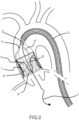
- the device is collapsed into the external shaft catheter 3 before to introduce it into the arterial vessel ( Figure 1 ).
- the distal portion of the external shaft catheter is equipped with a balloon catheter tip 2 deployed across the edge of the external shaft catheter 3.
- the function of this balloon tip is to avoid any arterial wall damage during the device traveling towards the ascending aorta while ensuring precise positioning being inflated with radiopaque solution.
- the balloon tip is deflated and retracted outside the patient's body.
- the device is deployed inside the ascending aorta retracting the external shaft catheter 3.
- the external support structures 5 are fitting the aorta's wall in order to convey all blood into the device.
- the device 4 is connected to the internal shaft catheter 3' by means of struts or theters 4'. Internally, the device has two components sustained by the external support structure 5: the conveyor 6 and the valve prosthesis 15.
- the conveyor 6 is proximally fixed to the proximal portion of the external support 5 and delimits "like a funnel" a channel 6' inside the device.
- the role of the conveyor is to allow devices (valvuloplasty balloons or TAVI, etc..) crossing towards the aortic valve.
- another function of the conveyor 6 is to support the antiembolic filter.
- the role of the prosthetic valve, equipped with two, three or more leaflets, is to avoid a massive blood flow regurgitation during interventional procedures on the native aortic valve (e.g.
- the prosthetic valve 15 can be directly anchored to the distal edge of the external support structure 5 but in the described embodiment it is mounted on an independent valve support and joined to the external support structure 5 by a diaphragm of fabric.
- the valve function is granted by the coaptation of the leaflets that in closure phase adhere to the distal external surface of the conveyor 6.
- Figures 2 and 2a respectively show the device 4 and the diseased valve respectively in the closed and open positions.
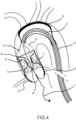
- the device is represented deployed as in figure 2 but the device is equipped with an additional feature represented by two coronary artery filters 8 and one epiaortic vessels filter 9.
- the first one impedes possible debris embolizations into the coronary ostia during an interventional procedure on the aortic valve. This event despite being not very frequent is very often catastrophic.
- the second one is aimed at avoiding possible residual debris, accidentally not completely captured by the device 4, to embolize towards the brain causing a stroke.
- This deflector can be deployed, in case of high risk procedures, by further retracting the external shaft catheter 3.
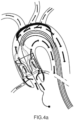
- Figure 4 details the blood flow direction in systole, with the main flow pattern trough the aorta, together with the flow pattern through the epiaortic vessels and a flow trough the coronary artery, granted by a non complete sealing of the coronary ostia by the native valve.
- the embolic debris are captured and remain inside the structure in between the conveyor 6 and the external support structure 5.
- the device can be left in place for a period in order to allow a stabilization of the patient's haemodynamics and then removed.
- a specific mechanism can be used that forces the prosthetic valve open to verify the native valve functionality restoring upon treatment and repeat the treatment if needed.
- the above mentioned valve opening mechanism can be virtually applied in any of the specific embodiment here-below described.
- the devices that operated on the aortic native valve are removed out from the internal lumen of the conveyor 6'.
- the device 4 is completely retrieved by pushing distally the external shaft catheter 3. In this way, the device structures gradually collaps until reaching the distal end of the device safely keeping inside it all captured clots or calcium debris.
- the device 4 is conceived to provide an effective antiembolic protection during interventional procedures on the native aortic valve as well as support the blood circulation in case an aortic valve insufficiency is present.
- the device In another future condition the device is absolutely necessary. It is the case in which the diseased native aortic valve is removed with an interventional off-pump procedure. In this complex procedure during the dissection of the native valve an antiembolic protection is mandatory and even more important an ancillary aortic valve function is demanded in the meantime a sutureless valve prosthesis is implanted.
- the device can answer to all these needs.
- valve that is integrating in one single device the antiembolic filter and a valve prosthesis could provide the two components detachable.
- the prosthetic valve could be detached from the device 4 and left in place as a permanent sutureless valve prosthesis similar to a TAVI procedure.
- the valve allows to temporarily replace the diseased valve during the procedure, while allowing hydrodynamic performances compatible with clinical conditions of patients with aortic stenosis.
- the support structure can be either a single element structure 5'' or a multielement one. In the first case, it has the functions of coupling with the aorta, support the valve and filter and act as conveyor. In the second case, the external support 5 has the function of coupling with the aorta and support other structures.
- the valve's support stent 14 has the aim to support the valve leaflets; the conveyor support 6 is here below described.
- the internal surface of the support 5 (5'') is covered by an antiembolic tissue mesh 12 in order to allow a better sealing of the device against the aortic wall but also to impede emboli migration in case of limited contact.
- the filter 12 allows to retain the emboli debris without significantly alter the hydrodynamic characteristics of the valve.
- the filter and the conveyor fabric are joined in a unique element.
- the conveyor 6 is the introducer element of the TVAF: it makes an easier in situ positioning of specific devices (i.e. TAVI) loaded with external catheter 3, thanks to the geometry of its elements.
- TAVI specific devices
- the conveyor 6 and the valve's support stent 14 are joined in a unique element 5".
- the internal shaft catheter 3' support the device 4, permanently in the default set-up.
- the internal shaft catheter is protected by the external shaft catheter 3 that has the function to guide the device in position and to allow the deployment/recapture of the device 4.
- the support structures are here described as made for most of the embodiments by self-expanding metallic materials like nitinol, but also other metallic and non metallic materials with similar characteristics can apply and also non self-expandable sructures like polymeric inflatable ones can apply;
- the filter is described as a polymeric woven fabric, but also non-woven (i.e. membrane with calibrated holes) and or metallic materials with similar characteristics can apply;
- the valve is described as a polymeric woven fabric coated for ensuring leak-free characteristics, but also non-woven with similar characteristics can apply;
- the catheters comprises a polymeric tube, but also a metal-reinforced polymeric tube.
- the metallic support structures are described as obtained by laser cutting tubes or welded sheets, by woven (i.e. by a plurality strands) and single wire structures;
- the coupling between the different elements of the device can be either glueing, soldering, welding (i.e. ultrasound), adhering, sewing, and other applicable methods;
- the valve can be obtained by coating of a fabric, but also other synthetic or natural materials can also apply, such as a polymeric membrane.
- valve part can be disloged by the rest of the assembly can apply, in order to be used as a TAVI or a sutureless valve prosthesis.
- the valves' leaflets can be manufactured with material different respect to polymeric ones, such as pericardial tissue or other and the valve structure can also have specific retrieval elements.
- the device can also apply in other technical fields, such as the interventional radiology, as a valved, or not, filter for carotid artery protection as well as a repositionable/recapturable venous valve with antiembolic filter.
- the interventional radiology as a valved, or not, filter for carotid artery protection as well as a repositionable/recapturable venous valve with antiembolic filter.
- specific embodiments and dimension for the different elements to be used amongst the default set-up (valve, filter, conveyor and relevant support structures, catheters) and the expected use (acute, subacute, chronic) will apply.
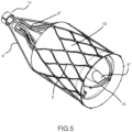
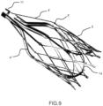
- Figures from 5 to 11 show one embodiment, herebelow referred as hybrid device being the techonology used for manufacturing the self-expandable nitinol structures laser cutting for the external support structure 5 and valve's support stent 14 and braiding or wiring for the conveyor 6.
- the external support structure 5 and the inner valve's support stent 14 are connected by a sort of diaphragm 13, thus ensuring deployment of the inner prosthetic valve 15 independent respect to the external support 5 and antiembolic filter elements.
- the conveyor 6, which also acts as the filter support, is positioned inside the external structure 5 in order to reduce the overall device length.
- a long axis view of the device in deployed configuration shows the rings that permanently joints the internal shaft catheter 3' to the external self-expandable support structure 5 and the conveyor 6 and valve's support stent 14 by means of the tethering struts 4' and 4".
- a short axis (ventricular) view of the device 4 in a deployed configuration shows the anchoring holes between the external structure 5 and the mesh 10, that is reverted at the distal side and is joined to the valve prosthesis 15 leaflets 7, these latter covering the external side of the self-expandable material internal valve's support stent 14.
- the absence of leakage in the diastolic phase is guaranteed by the impermeable mesh of the leaflet elements 7 and of the mesh 10 together with the configuration of the conveyor conduit, which is distally equipped with a bi-directional normally closed valve 6".
- valve 6" Both in systole and diastole the valve 6" remains closed, in order to prevent any blood and possible embolic particles leakage; when the trans catheter devices are introduced, the distal conveyor's tube 6" extends in diameter facilitating their introduction maintaining a proper alignment, whilst the valve 6" allows a virtually leak free crossing of the device.
- the valve 6" can be either directly operated by the delivery system or automatically, remaining strictly closed at the systolic and diastolic differential pressure, but capable to be crossed by the insterted device delivery system, whilst maintaining a leak free coupling.
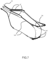
- Figure 7 shows the self-expandable internal valve's support stent 14, which supports both the commisures of the leaflet 7 and the overall inflow profile of the said leaflets 7 with specific joints 14', which contoures the structure from the external side.
- This configuration allows minimization of the pressure drop in the systolic phase thanks to a wide and cylindrical leaflet opening and minimization of the closure and leakage backflow regurgitation during the diastolic phase.
- the tethering struts 4'' allow a direct joining with the internal shaft catheter 3' with adequate independence respect to the external support 5.
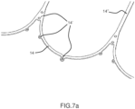
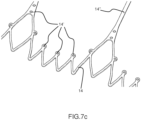
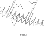
- Figures 7a , 7b , 7c , 7d and 7e show alternative configurations of inflow profiles for ensuring at the same time adequate retrievability and radial stiffness.
- Figure 8 shows the self-expandable external support structure 5, which support the conveyor 6 and relevant filter mesh 12 at the anchoring holes 5' side and the coupling of the mesh 10 with the inflow side of the leaflets 7.
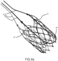
- conveyor 6 and valve's stent support 14 can be combined in a single element 5" to be joined to the external structure 5 by a tethered struts with keyholes 5′′′ as described in figures 9a and 9b .
- the conical shape of the conveyor guarantees first a smooth and easy crossing by the devices loaded with external catheter different than the external 3; second, it is covered with a filter 12 of adequate mesh and surface, in order to minimize relevant pressure drop in the systolic phase and filter any possible embolization debris deriving from the procedure and maintain it in the collection chamber obtained between the mesh 12 and 10; third, it guarantees a smooth retrieve.
- the distal end of the conveyor is cilindrical with axis aligned with the diseased valve to be treated, to guarantee a proper alignment of the loaded device. Furthermore, this cilindrical part has radial compliance adequate to minimize the force to be applied for loading and retrieving the device through the delivery system.
- FIG 10a the same elements are viewn from the inflow side (ventricle view), with the bi-directional normally closed valve at the distal part of the conveyor shown, that guarantees no flow both in systole, to impede any embolization to cross the device 4, nor in diastole, to minimize overall leakage, whilst allowing the loaded device crossing through the device 4.
- figure 10 and 10a show the prosthetic valve body 15 from the outflow and inflow side.
- the trileaflet configuration was selected, with leaflets made of a low thickness polymeric fabric elastomerically coated and installed outside the supporting structure 14 in order to guarantee a wide leaflet cylindrical open configuration.
- This design configuration guarantees optimal pliability/foldability and at the same type relatively low extensibility, thus optimal hemodynamics and mechanical characteristics.
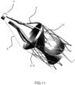
- Figure 11 shows the configuration of the device 4 assembled without the mesh 10, in order to visualize the mutual positioning of the conveyor/filter and of the valve respect to the relevant external 5 and valve's support stent 14 support structures.
- Radiopaque markers are placed in order to better detect specific locations, such as the posts and side access, and internal catheter locations, such as the aortic arch level. Materials, joining mechanism and number of elements are selected based at the state of the art and based on the current procedures.
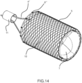
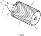
- FIGS. 12 to 15 show an alternative embodiment, configured as well as the hybrid one with a conveyor internal to the body, in order to minimize overall length, but with both the external support structure 5 and the conveyor 6 made of a superelastic metallic mesh, therefore referred as mesh embodiment.
- Another difference respect to the hybrid embodiment is that in the mesh embodiment the external support structure 5 directly provides an anchoring surface for the leaflet of prosthetic valve 15.
- Figure 12 shows a lateral view of the mesh assembly, with the external cylindrical structure 5 and the mesh 10, the conveyor 6 and relevant mesh 12, the prosthetic valve 15, together with the relevant coupling between the elements.
- the coupling elements of the superelastic metallic external structure 5 are as follows: a tethering structure 4', which is permanently joined to the internal catheter 3' by means of a ring 11, sustains the external structure 5 and the inflow side of the conveyor 6, whilst allowing the mutual sliding of the elements to allow proper self expanding and retrieval; a cylindrical tube mesh 10, acts as a mutual joint elements between the external structure 5 and the prosthetic valve 15, namely with sewing/ultrasound welding them at the inflow and outflow sides to the tube 10 and to the valve along its inflow side profile.
- FIG 14 the external support structure 5 and internal valve's support stent 14 anchored to its internal wall are shown.
- This embodiment is different respect to the hybrid one because it misses an internal metallic support structure in order to optimize the low profile characteristics of the device rather than having an independent valve anchoring.
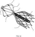
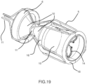
- Figures from 16 to 18 show a device 4 derived from the hybrid, but with the conveyor 6 system placed proximally outside the device.
- this embodiment can guarantee, in principle, an alignment of the loaded device better than the previous ones due to a longer distal conveyor tube and an easier retrieval inside small caliper external catheter 3 thanks to the reduced number of elements put one inside the other.
- the coupling at 11' must be flexible in order to follow the aortic arch pattern at the proximal conveyor side, whilst guaranteeing a stable anchoring to the aorta at the distal side.
- Figures 16 , 16a , 17 , 18 show the elements similar to the hybrid ones (namely the coupling amongst the prosthetic valve 15 and its valve's support stent 14, the coupling amongst the mesh 10 and the external structure 5) and the main differences: the conveyor cone 6 is proximal, it is placed outside of the external structure 5, and it is half distally covered with a filtering mesh that can have only the mechanical function of driving the movement of the loaded devices towards the internal lumen of the conveyor; the antembolic filter mesh 12, viceversa, is in the conical part of the external structure, distal respect to the ring 11'.
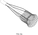
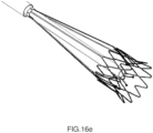
- Figures 16b , 16c , 16d and 16e show, respectively, two laser cut and two braided alternative embodiments of the external structure 5 of the hybrid device 4, with different ratio between diamonds and straight elements in order to be more oriented to radial stiffness or retrievability characteristics.
- Figure 16f shows a self expanding structure that combines the characteristics of the external 5 and valve's stent 14 support structures in one, devoting the last one on holding only the leaflets posts. This embodiment is intended to minimize the radial thickness of the supporting structure in order to maximize the retrievability.
- Figure 16g shows a self expanding structure similar to the hybrid mesh, in which two diamond structures at the inflow and outflow sides of the valve are joined by linear elements in order to avoid overall length variation of this region at retrieval and a skirt element.
- inflatable structures has the aim to minimize the number of different materials involved in the manufacturing and it allows a reduced encumbrance of the collapsed device. Moreover it allows an easy positioning of the device thanks to the radiopaque characterisitcs of the CO 2 filler.
Landscapes
- Health & Medical Sciences (AREA)
- Cardiology (AREA)
- Biomedical Technology (AREA)
- Engineering & Computer Science (AREA)
- Life Sciences & Earth Sciences (AREA)
- General Health & Medical Sciences (AREA)
- Veterinary Medicine (AREA)
- Heart & Thoracic Surgery (AREA)
- Public Health (AREA)
- Animal Behavior & Ethology (AREA)
- Oral & Maxillofacial Surgery (AREA)
- Transplantation (AREA)
- Vascular Medicine (AREA)
- Surgery (AREA)
- Pathology (AREA)
- Nuclear Medicine, Radiotherapy & Molecular Imaging (AREA)
- Medical Informatics (AREA)
- Molecular Biology (AREA)
- Prostheses (AREA)
- Surgical Instruments (AREA)
- Media Introduction/Drainage Providing Device (AREA)
Claims (7)
- Vorübergehende Transkatheter-Klappenprothese für Blutgefäß, umfassend eine expandierbare Stützstruktur (5), eine Klappe (7), einen Filter (12) und eine Fördereinrichtung (6), wobei die Stützstruktur (5) eine rohrförmige Gestalt mit einem distalen und einem proximalen Ende bildet, wenn sie expandiert ist, wobei die Klappe (7) an dem distalen Ende angeordnet ist und sich die Fördereinrichtung (6) in der Stützstruktur (5) erstreckt und einen Trichterabschnitt, der an dem proximalen Ende angeordnet ist, und einen rohrförmigen Teil umfasst, der an dem distalen Ende angeordnet ist, wobei der rohrförmige Teil dazu ausgeführt ist, als Einführungsvorrichtung für andere Vorrichtungen zu dienen.
- Prothese nach Anspruch 1, wobei der Filter (12) und die Fördereinrichtung (6) so kombiniert sind, dass sie ein einziges Element bilden.
- Prothese nach Anspruch 1, wobei der Filter (12) an der Innenwand der Stützstruktur (5) angeordnet ist.
- Prothese nach Anspruch 1, 2 oder 3, dadurch gekennzeichnet, dass das distale Ende der Fördereinrichtung (6) eine bidirektionale normalerweise geschlossene Klappe enthält, die nach Bedarf durchquert werden kann, um als eine leckfreie Einführungsvorrichtung für andere Vorrichtungen (6") zu dienen.
- Prothese nach einem der vorhergehenden Ansprüche, wobei die Klappe (7) mehrere Segel umfasst.
- Prothese nach einem der vorhergehenden Ansprüche, wobei die Klappe (7), der Filter (12) und die Fördereinrichtung (6) in der Stützstruktur (5") angeordnet sind.
- Prothese nach einem der vorhergehenden Ansprüche, wobei die Stützstruktur (5) einen konischen Abschluss hat, der eine Vielzahl von Anbindungsstreben (4', 4") umfasst, die dazu ausgeführt sind, mit einem inneren Katheter (3') verbunden zu werden, wobei die Struktur aus dem expandierten in den komprimierten Zustand zusammenfaltbar ist, indem an den Anbindungsstreben (4', 4") gezogen wird.
Applications Claiming Priority (2)
| Application Number | Priority Date | Filing Date | Title |
|---|---|---|---|
| EP17171583.2A EP3403615A1 (de) | 2017-05-17 | 2017-05-17 | Transkatheterventilprothese für blutgefäss |
| PCT/IB2018/052807 WO2018211344A1 (en) | 2017-05-17 | 2018-04-23 | Transcatheter valve prosthesis for blood vessel |
Publications (2)
| Publication Number | Publication Date |
|---|---|
| EP3624732A1 EP3624732A1 (de) | 2020-03-25 |
| EP3624732B1 true EP3624732B1 (de) | 2024-11-27 |
Family
ID=58715067
Family Applications (2)
| Application Number | Title | Priority Date | Filing Date |
|---|---|---|---|
| EP17171583.2A Withdrawn EP3403615A1 (de) | 2017-05-17 | 2017-05-17 | Transkatheterventilprothese für blutgefäss |
| EP18727425.3A Active EP3624732B1 (de) | 2017-05-17 | 2018-04-23 | Transkatheterventilprothese für blutgefäss |
Family Applications Before (1)
| Application Number | Title | Priority Date | Filing Date |
|---|---|---|---|
| EP17171583.2A Withdrawn EP3403615A1 (de) | 2017-05-17 | 2017-05-17 | Transkatheterventilprothese für blutgefäss |
Country Status (5)
| Country | Link |
|---|---|
| US (1) | US11559396B2 (de) |
| EP (2) | EP3403615A1 (de) |
| JP (1) | JP7245823B2 (de) |
| CN (1) | CN110769781B (de) |
| WO (1) | WO2018211344A1 (de) |
Cited By (6)
| Publication number | Priority date | Publication date | Assignee | Title |
|---|---|---|---|---|
| US12343568B2 (en) | 2020-08-27 | 2025-07-01 | The Regents Of The University Of Michigan | Ultrasound transducer with transmit-receive capability for histotripsy |
| US12420118B2 (en) | 2018-11-28 | 2025-09-23 | Histosonics, Inc. | Histotripsy systems and methods |
| US12446905B2 (en) | 2023-04-20 | 2025-10-21 | Histosonics, Inc. | Histotripsy systems and associated methods including user interfaces and workflows for treatment planning and therapy |
| US12527976B2 (en) | 2020-06-18 | 2026-01-20 | Histosonics, Inc. | Histotripsy acoustic and patient coupling systems and methods |
| US12582848B2 (en) | 2021-06-07 | 2026-03-24 | The Regents Of The University Of Michigan | Minimally invasive histotripsy systems and methods |
| US12599787B2 (en) | 2021-06-07 | 2026-04-14 | The Regents Of The University Of Michigan | All-in-one ultrasound systems and methods including histotripsy |
Families Citing this family (11)
| Publication number | Priority date | Publication date | Assignee | Title |
|---|---|---|---|---|
| JP7298826B2 (ja) | 2017-09-12 | 2023-06-27 | アオルティクラブ エスアールエル | 石灰化した心臓弁尖を治療するための経カテーテル装置 |
| EP3685772A1 (de) | 2019-01-24 | 2020-07-29 | Aorticlab Sarl | Vorrichtung zur behandlung von gewebeverkalkung |
| CN113677296B (zh) | 2019-02-13 | 2024-12-31 | 艾姆伯莱恩公司 | 具有整合的栓塞防护装置的导管 |
| EP3718505A1 (de) | 2019-04-05 | 2020-10-07 | Aorticlab Sarl | Transkatheter-anti-embolie-filter für arterielle und venöse gefässe |
| EP4051171A4 (de) * | 2019-11-01 | 2023-12-20 | Silk Road Medical, Inc. | Systeme und verfahren zur transkatheter-aortenklappen-behandlung |
| US20220151776A1 (en) * | 2020-11-16 | 2022-05-19 | The Regents Of The University Of California | Temporary Vascular Valve and Related Systems and Methods |
| CN114681126B (zh) * | 2020-12-28 | 2025-02-18 | 杭州德晋医疗科技有限公司 | 多支架的瓣膜扩张器及瓣膜扩张系统 |
| CN112494176A (zh) * | 2021-01-06 | 2021-03-16 | 四川大学华西医院 | 一种主动脉通道球囊 |
| WO2023062551A1 (en) | 2021-10-12 | 2023-04-20 | Laguna Tech Usa, Inc. | Prosthesis heart valve device, delivery system, interventional system and relate method |
| IT202100029579A1 (it) | 2021-11-23 | 2023-05-23 | Leafmate S R L | Dispositivo con valvola temporanea per operazioni percutanee su valvola aortica nativa o artificiale |
| CN117159229B (zh) * | 2023-05-24 | 2026-03-31 | 杭州启明医疗器械股份有限公司 | 便于旋转的介入系统 |
Family Cites Families (23)
| Publication number | Priority date | Publication date | Assignee | Title |
|---|---|---|---|---|
| CA2361670C (en) * | 1999-01-27 | 2010-03-30 | Viacor Incorporated | Cardiac valve procedure methods and devices |
| US7749245B2 (en) * | 2000-01-27 | 2010-07-06 | Medtronic, Inc. | Cardiac valve procedure methods and devices |
| WO2002047539A2 (en) * | 2000-12-15 | 2002-06-20 | Viacor, Inc. | Apparatus and method for replacing aortic valve |
| US7011094B2 (en) * | 2001-03-02 | 2006-03-14 | Emphasys Medical, Inc. | Bronchial flow control devices and methods of use |
| EP1583581A4 (de) | 2002-11-13 | 2008-09-10 | Medtronic Inc | Herzklappenverfahren und vorrichtungen |
| US20050137696A1 (en) * | 2003-12-23 | 2005-06-23 | Sadra Medical | Apparatus and methods for protecting against embolization during endovascular heart valve replacement |
| US7569071B2 (en) * | 2005-09-21 | 2009-08-04 | Boston Scientific Scimed, Inc. | Venous valve, system, and method with sinus pocket |
| WO2008097556A1 (en) | 2007-02-05 | 2008-08-14 | Boston Scientific Limited | Systems and methods for valve delivery |
| AU2008288796B2 (en) * | 2007-08-23 | 2014-03-20 | Dfm, Llc | Cardiovascular prosthetic valve |
| EP2603172A4 (de) * | 2010-08-09 | 2014-10-22 | Valvexchange Inc | Temporäres subvalvuläres prüfventil |
| EP2522307B1 (de) * | 2011-05-08 | 2020-09-30 | ITSO Medical AB | Vorrichtung zur Lieferung von medizinischen Geräten an eine Herzklappe |
| US9492265B2 (en) * | 2012-01-06 | 2016-11-15 | Emboline, Inc. | Integrated embolic protection devices |
| US8735702B1 (en) * | 2012-03-21 | 2014-05-27 | Deborah R. Miles | Portable dissipating medium used for removal of vibrational interference in a bowed string of a violin family instrument |
| WO2013152244A2 (en) * | 2012-04-06 | 2013-10-10 | Pi-R-Squared Ltd. | Percutaneous emboli protection sleeve |
| WO2014117087A1 (en) * | 2013-01-25 | 2014-07-31 | Apica Cardiovascular Limited | Systems and methods for percutaneous access, stabilization and closure of organs |
| FR3020265B1 (fr) * | 2014-04-24 | 2019-09-06 | Cormove | Dispositif de mise en place d'une etancheite autour d'un implant dans un passage de circulation du sang, et necessaire de traitement associe |
| WO2015184450A1 (en) * | 2014-05-30 | 2015-12-03 | Cardiac Valve Solutions Llc | Temporary valve and filter on guide catheter |
| FR3021860A1 (fr) | 2014-06-05 | 2015-12-11 | Bernard Pain | Dispositif transcatheter pour l'ablation de tissus calcifies au niveau des volets d'une valve aortique |
| FR3021863A1 (fr) | 2014-06-05 | 2015-12-11 | Bernard Pain | Dispositif d'introduction transcatheter dans la racine aortique au niveau de la jonction sino tubulaire |
| KR102452779B1 (ko) * | 2014-09-14 | 2022-10-07 | 엠볼린, 인크. | 색전 보호를 동반하는 도입 시스 |
| JP7298826B2 (ja) | 2017-09-12 | 2023-06-27 | アオルティクラブ エスアールエル | 石灰化した心臓弁尖を治療するための経カテーテル装置 |
| FR3091838B1 (fr) | 2019-01-22 | 2021-02-12 | Valeo Embrayages | Module de propulsion d’un véhicule électrique ou hybride |
| EP3718505A1 (de) | 2019-04-05 | 2020-10-07 | Aorticlab Sarl | Transkatheter-anti-embolie-filter für arterielle und venöse gefässe |
-
2017
- 2017-05-17 EP EP17171583.2A patent/EP3403615A1/de not_active Withdrawn
-
2018
- 2018-04-23 US US16/610,540 patent/US11559396B2/en active Active
- 2018-04-23 JP JP2020514782A patent/JP7245823B2/ja active Active
- 2018-04-23 EP EP18727425.3A patent/EP3624732B1/de active Active
- 2018-04-23 CN CN201880032202.0A patent/CN110769781B/zh active Active
- 2018-04-23 WO PCT/IB2018/052807 patent/WO2018211344A1/en not_active Ceased
Cited By (10)
| Publication number | Priority date | Publication date | Assignee | Title |
|---|---|---|---|---|
| US12420118B2 (en) | 2018-11-28 | 2025-09-23 | Histosonics, Inc. | Histotripsy systems and methods |
| US12491384B2 (en) | 2018-11-28 | 2025-12-09 | Histosonics, Inc. | Histotripsy systems and methods |
| US12491382B2 (en) | 2018-11-28 | 2025-12-09 | Histosonics, Inc. | Histotripsy systems and methods |
| US12589261B2 (en) | 2018-11-28 | 2026-03-31 | Histosonics, Inc. | Histotripsy systems and methods |
| US12599784B2 (en) | 2018-11-28 | 2026-04-14 | Histosonics, Inc. | Histotripsy systems and methods |
| US12527976B2 (en) | 2020-06-18 | 2026-01-20 | Histosonics, Inc. | Histotripsy acoustic and patient coupling systems and methods |
| US12343568B2 (en) | 2020-08-27 | 2025-07-01 | The Regents Of The University Of Michigan | Ultrasound transducer with transmit-receive capability for histotripsy |
| US12582848B2 (en) | 2021-06-07 | 2026-03-24 | The Regents Of The University Of Michigan | Minimally invasive histotripsy systems and methods |
| US12599787B2 (en) | 2021-06-07 | 2026-04-14 | The Regents Of The University Of Michigan | All-in-one ultrasound systems and methods including histotripsy |
| US12446905B2 (en) | 2023-04-20 | 2025-10-21 | Histosonics, Inc. | Histotripsy systems and associated methods including user interfaces and workflows for treatment planning and therapy |
Also Published As
| Publication number | Publication date |
|---|---|
| EP3403615A1 (de) | 2018-11-21 |
| US20200069421A1 (en) | 2020-03-05 |
| WO2018211344A1 (en) | 2018-11-22 |
| EP3624732A1 (de) | 2020-03-25 |
| JP2020520296A (ja) | 2020-07-09 |
| US11559396B2 (en) | 2023-01-24 |
| CN110769781B (zh) | 2022-02-11 |
| JP7245823B2 (ja) | 2023-03-24 |
| CN110769781A (zh) | 2020-02-07 |
| CA3062508A1 (en) | 2018-11-22 |
Similar Documents
| Publication | Publication Date | Title |
|---|---|---|
| EP3624732B1 (de) | Transkatheterventilprothese für blutgefäss | |
| JP7485383B2 (ja) | 動脈および静脈用の経カテーテル塞栓防止フィルタ | |
| US11284999B2 (en) | Stents for prosthetic heart valves | |
| AU2004311967B2 (en) | Apparatus and methods for heart valve replacement | |
| US10813740B2 (en) | Embolic protection device | |
| US9999506B2 (en) | System and method for treating valve insufficiency or vessel dilatation | |
| US10016274B2 (en) | Stent for prosthetic heart valves | |
| US20170056215A1 (en) | Stent assemblies including passages to provide blood flow to coronary arteries and methods of delivering and deploying such stent assemblies | |
| CA3062508C (en) | Transcatheter valve prosthesis for blood vessel | |
| AU2011202667B2 (en) | Apparatus and methods for heart valve replacement | |
| CA3130859C (en) | Transcatheter anti embolic filter for arterial and venous vessels |
Legal Events
| Date | Code | Title | Description |
|---|---|---|---|
| STAA | Information on the status of an ep patent application or granted ep patent |
Free format text: STATUS: UNKNOWN |
|
| STAA | Information on the status of an ep patent application or granted ep patent |
Free format text: STATUS: THE INTERNATIONAL PUBLICATION HAS BEEN MADE |
|
| PUAI | Public reference made under article 153(3) epc to a published international application that has entered the european phase |
Free format text: ORIGINAL CODE: 0009012 |
|
| STAA | Information on the status of an ep patent application or granted ep patent |
Free format text: STATUS: REQUEST FOR EXAMINATION WAS MADE |
|
| 17P | Request for examination filed |
Effective date: 20191213 |
|
| AK | Designated contracting states |
Kind code of ref document: A1 Designated state(s): AL AT BE BG CH CY CZ DE DK EE ES FI FR GB GR HR HU IE IS IT LI LT LU LV MC MK MT NL NO PL PT RO RS SE SI SK SM TR |
|
| AX | Request for extension of the european patent |
Extension state: BA ME |
|
| DAV | Request for validation of the european patent (deleted) | ||
| DAX | Request for extension of the european patent (deleted) | ||
| STAA | Information on the status of an ep patent application or granted ep patent |
Free format text: STATUS: EXAMINATION IS IN PROGRESS |
|
| 17Q | First examination report despatched |
Effective date: 20240424 |
|
| GRAP | Despatch of communication of intention to grant a patent |
Free format text: ORIGINAL CODE: EPIDOSNIGR1 |
|
| STAA | Information on the status of an ep patent application or granted ep patent |
Free format text: STATUS: GRANT OF PATENT IS INTENDED |
|
| INTG | Intention to grant announced |
Effective date: 20240626 |
|
| GRAS | Grant fee paid |
Free format text: ORIGINAL CODE: EPIDOSNIGR3 |
|
| GRAA | (expected) grant |
Free format text: ORIGINAL CODE: 0009210 |
|
| STAA | Information on the status of an ep patent application or granted ep patent |
Free format text: STATUS: THE PATENT HAS BEEN GRANTED |
|
| AK | Designated contracting states |
Kind code of ref document: B1 Designated state(s): AL AT BE BG CH CY CZ DE DK EE ES FI FR GB GR HR HU IE IS IT LI LT LU LV MC MK MT NL NO PL PT RO RS SE SI SK SM TR |
|
| REG | Reference to a national code |
Ref country code: GB Ref legal event code: FG4D |
|
| REG | Reference to a national code |
Ref country code: CH Ref legal event code: EP |
|
| REG | Reference to a national code |
Ref country code: IE Ref legal event code: FG4D |
|
| REG | Reference to a national code |
Ref country code: DE Ref legal event code: R096 Ref document number: 602018076949 Country of ref document: DE |
|
| REG | Reference to a national code |
Ref country code: LT Ref legal event code: MG9D |
|
| REG | Reference to a national code |
Ref country code: NL Ref legal event code: MP Effective date: 20241127 |
|
| PG25 | Lapsed in a contracting state [announced via postgrant information from national office to epo] |
Ref country code: HR Free format text: LAPSE BECAUSE OF FAILURE TO SUBMIT A TRANSLATION OF THE DESCRIPTION OR TO PAY THE FEE WITHIN THE PRESCRIBED TIME-LIMIT Effective date: 20241127 Ref country code: PT Free format text: LAPSE BECAUSE OF FAILURE TO SUBMIT A TRANSLATION OF THE DESCRIPTION OR TO PAY THE FEE WITHIN THE PRESCRIBED TIME-LIMIT Effective date: 20250327 Ref country code: IS Free format text: LAPSE BECAUSE OF FAILURE TO SUBMIT A TRANSLATION OF THE DESCRIPTION OR TO PAY THE FEE WITHIN THE PRESCRIBED TIME-LIMIT Effective date: 20250327 |
|
| PG25 | Lapsed in a contracting state [announced via postgrant information from national office to epo] |
Ref country code: FI Free format text: LAPSE BECAUSE OF FAILURE TO SUBMIT A TRANSLATION OF THE DESCRIPTION OR TO PAY THE FEE WITHIN THE PRESCRIBED TIME-LIMIT Effective date: 20241127 Ref country code: NL Free format text: LAPSE BECAUSE OF FAILURE TO SUBMIT A TRANSLATION OF THE DESCRIPTION OR TO PAY THE FEE WITHIN THE PRESCRIBED TIME-LIMIT Effective date: 20241127 |
|
| REG | Reference to a national code |
Ref country code: AT Ref legal event code: MK05 Ref document number: 1745001 Country of ref document: AT Kind code of ref document: T Effective date: 20241127 |
|
| PG25 | Lapsed in a contracting state [announced via postgrant information from national office to epo] |
Ref country code: BG Free format text: LAPSE BECAUSE OF FAILURE TO SUBMIT A TRANSLATION OF THE DESCRIPTION OR TO PAY THE FEE WITHIN THE PRESCRIBED TIME-LIMIT Effective date: 20241127 |
|
| PG25 | Lapsed in a contracting state [announced via postgrant information from national office to epo] |
Ref country code: ES Free format text: LAPSE BECAUSE OF FAILURE TO SUBMIT A TRANSLATION OF THE DESCRIPTION OR TO PAY THE FEE WITHIN THE PRESCRIBED TIME-LIMIT Effective date: 20241127 |
|
| PG25 | Lapsed in a contracting state [announced via postgrant information from national office to epo] |
Ref country code: NO Free format text: LAPSE BECAUSE OF FAILURE TO SUBMIT A TRANSLATION OF THE DESCRIPTION OR TO PAY THE FEE WITHIN THE PRESCRIBED TIME-LIMIT Effective date: 20250227 |
|
| PG25 | Lapsed in a contracting state [announced via postgrant information from national office to epo] |
Ref country code: GR Free format text: LAPSE BECAUSE OF FAILURE TO SUBMIT A TRANSLATION OF THE DESCRIPTION OR TO PAY THE FEE WITHIN THE PRESCRIBED TIME-LIMIT Effective date: 20250228 Ref country code: LV Free format text: LAPSE BECAUSE OF FAILURE TO SUBMIT A TRANSLATION OF THE DESCRIPTION OR TO PAY THE FEE WITHIN THE PRESCRIBED TIME-LIMIT Effective date: 20241127 Ref country code: AT Free format text: LAPSE BECAUSE OF FAILURE TO SUBMIT A TRANSLATION OF THE DESCRIPTION OR TO PAY THE FEE WITHIN THE PRESCRIBED TIME-LIMIT Effective date: 20241127 |
|
| PG25 | Lapsed in a contracting state [announced via postgrant information from national office to epo] |
Ref country code: PL Free format text: LAPSE BECAUSE OF FAILURE TO SUBMIT A TRANSLATION OF THE DESCRIPTION OR TO PAY THE FEE WITHIN THE PRESCRIBED TIME-LIMIT Effective date: 20241127 |
|
| PG25 | Lapsed in a contracting state [announced via postgrant information from national office to epo] |
Ref country code: RS Free format text: LAPSE BECAUSE OF FAILURE TO SUBMIT A TRANSLATION OF THE DESCRIPTION OR TO PAY THE FEE WITHIN THE PRESCRIBED TIME-LIMIT Effective date: 20250227 |
|
| PG25 | Lapsed in a contracting state [announced via postgrant information from national office to epo] |
Ref country code: SM Free format text: LAPSE BECAUSE OF FAILURE TO SUBMIT A TRANSLATION OF THE DESCRIPTION OR TO PAY THE FEE WITHIN THE PRESCRIBED TIME-LIMIT Effective date: 20241127 |
|
| PGFP | Annual fee paid to national office [announced via postgrant information from national office to epo] |
Ref country code: DE Payment date: 20250429 Year of fee payment: 8 |
|
| PG25 | Lapsed in a contracting state [announced via postgrant information from national office to epo] |
Ref country code: DK Free format text: LAPSE BECAUSE OF FAILURE TO SUBMIT A TRANSLATION OF THE DESCRIPTION OR TO PAY THE FEE WITHIN THE PRESCRIBED TIME-LIMIT Effective date: 20241127 |
|
| PGFP | Annual fee paid to national office [announced via postgrant information from national office to epo] |
Ref country code: GB Payment date: 20250429 Year of fee payment: 8 |
|
| PGFP | Annual fee paid to national office [announced via postgrant information from national office to epo] |
Ref country code: IT Payment date: 20250429 Year of fee payment: 8 |
|
| PG25 | Lapsed in a contracting state [announced via postgrant information from national office to epo] |
Ref country code: EE Free format text: LAPSE BECAUSE OF FAILURE TO SUBMIT A TRANSLATION OF THE DESCRIPTION OR TO PAY THE FEE WITHIN THE PRESCRIBED TIME-LIMIT Effective date: 20241127 |
|
| PGFP | Annual fee paid to national office [announced via postgrant information from national office to epo] |
Ref country code: FR Payment date: 20250429 Year of fee payment: 8 |
|
| PG25 | Lapsed in a contracting state [announced via postgrant information from national office to epo] |
Ref country code: RO Free format text: LAPSE BECAUSE OF FAILURE TO SUBMIT A TRANSLATION OF THE DESCRIPTION OR TO PAY THE FEE WITHIN THE PRESCRIBED TIME-LIMIT Effective date: 20241127 |
|
| PG25 | Lapsed in a contracting state [announced via postgrant information from national office to epo] |
Ref country code: SK Free format text: LAPSE BECAUSE OF FAILURE TO SUBMIT A TRANSLATION OF THE DESCRIPTION OR TO PAY THE FEE WITHIN THE PRESCRIBED TIME-LIMIT Effective date: 20241127 |
|
| PG25 | Lapsed in a contracting state [announced via postgrant information from national office to epo] |
Ref country code: CZ Free format text: LAPSE BECAUSE OF FAILURE TO SUBMIT A TRANSLATION OF THE DESCRIPTION OR TO PAY THE FEE WITHIN THE PRESCRIBED TIME-LIMIT Effective date: 20241127 |
|
| REG | Reference to a national code |
Ref country code: DE Ref legal event code: R097 Ref document number: 602018076949 Country of ref document: DE |
|
| PG25 | Lapsed in a contracting state [announced via postgrant information from national office to epo] |
Ref country code: SE Free format text: LAPSE BECAUSE OF FAILURE TO SUBMIT A TRANSLATION OF THE DESCRIPTION OR TO PAY THE FEE WITHIN THE PRESCRIBED TIME-LIMIT Effective date: 20241127 |
|
| PLBE | No opposition filed within time limit |
Free format text: ORIGINAL CODE: 0009261 |
|
| STAA | Information on the status of an ep patent application or granted ep patent |
Free format text: STATUS: NO OPPOSITION FILED WITHIN TIME LIMIT |
|
| REG | Reference to a national code |
Ref country code: CH Ref legal event code: L10 Free format text: ST27 STATUS EVENT CODE: U-0-0-L10-L00 (AS PROVIDED BY THE NATIONAL OFFICE) Effective date: 20251008 |
|
| 26N | No opposition filed |
Effective date: 20250828 |
|
| REG | Reference to a national code |
Ref country code: CH Ref legal event code: H13 Free format text: ST27 STATUS EVENT CODE: U-0-0-H10-H13 (AS PROVIDED BY THE NATIONAL OFFICE) Effective date: 20251125 |
|
| PG25 | Lapsed in a contracting state [announced via postgrant information from national office to epo] |
Ref country code: LU Free format text: LAPSE BECAUSE OF NON-PAYMENT OF DUE FEES Effective date: 20250423 |
|
| PG25 | Lapsed in a contracting state [announced via postgrant information from national office to epo] |
Ref country code: MC Free format text: LAPSE BECAUSE OF FAILURE TO SUBMIT A TRANSLATION OF THE DESCRIPTION OR TO PAY THE FEE WITHIN THE PRESCRIBED TIME-LIMIT Effective date: 20241127 |
|
| REG | Reference to a national code |
Ref country code: BE Ref legal event code: MM Effective date: 20250430 |
|
| PG25 | Lapsed in a contracting state [announced via postgrant information from national office to epo] |
Ref country code: BE Free format text: LAPSE BECAUSE OF NON-PAYMENT OF DUE FEES Effective date: 20250430 |
|
| PG25 | Lapsed in a contracting state [announced via postgrant information from national office to epo] |
Ref country code: CH Free format text: LAPSE BECAUSE OF NON-PAYMENT OF DUE FEES Effective date: 20250430 |
|
| PG25 | Lapsed in a contracting state [announced via postgrant information from national office to epo] |
Ref country code: IE Free format text: LAPSE BECAUSE OF NON-PAYMENT OF DUE FEES Effective date: 20250423 |