EP3624312A1 - Verfahren zur herstellung eines flüssigkeitskühlmantels - Google Patents
Verfahren zur herstellung eines flüssigkeitskühlmantels Download PDFInfo
- Publication number
- EP3624312A1 EP3624312A1 EP18193980.2A EP18193980A EP3624312A1 EP 3624312 A1 EP3624312 A1 EP 3624312A1 EP 18193980 A EP18193980 A EP 18193980A EP 3624312 A1 EP3624312 A1 EP 3624312A1
- Authority
- EP
- European Patent Office
- Prior art keywords
- liquid cooling
- cooling jacket
- stator
- casting
- cold spray
- Prior art date
- Legal status (The legal status is an assumption and is not a legal conclusion. Google has not performed a legal analysis and makes no representation as to the accuracy of the status listed.)
- Granted
Links
Images


Classifications
-
- H—ELECTRICITY
- H02—GENERATION; CONVERSION OR DISTRIBUTION OF ELECTRIC POWER
- H02K—DYNAMO-ELECTRIC MACHINES
- H02K5/00—Casings; Enclosures; Supports
- H02K5/04—Casings or enclosures characterised by the shape, form or construction thereof
- H02K5/20—Casings or enclosures characterised by the shape, form or construction thereof with channels or ducts for flow of cooling medium
- H02K5/203—Casings or enclosures characterised by the shape, form or construction thereof with channels or ducts for flow of cooling medium specially adapted for liquids, e.g. cooling jackets
-
- H—ELECTRICITY
- H02—GENERATION; CONVERSION OR DISTRIBUTION OF ELECTRIC POWER
- H02K—DYNAMO-ELECTRIC MACHINES
- H02K15/00—Processes or apparatus specially adapted for manufacturing, assembling, maintaining or repairing of dynamo-electric machines
- H02K15/14—Casings; Enclosures; Supports
-
- H—ELECTRICITY
- H02—GENERATION; CONVERSION OR DISTRIBUTION OF ELECTRIC POWER
- H02K—DYNAMO-ELECTRIC MACHINES
- H02K5/00—Casings; Enclosures; Supports
- H02K5/04—Casings or enclosures characterised by the shape, form or construction thereof
- H02K5/06—Cast metal casings
Definitions
- the invention relates to methods for producing a liquid cooling jacket of a dynamoelectric machine, a stator with such a liquid cooling jacket and a dynamoelectric machine with such a stator.
- Dynamoelectric machines in particular highly used dynamoelectric machines, require sufficient cooling to ensure proper operation.
- a surface-cooled machine is not always enough.
- liquid cooling jackets are arranged around the stators of dynamoelectric machines in order to efficiently dissipate the heat loss.
- Such liquid cooling jackets are complex to produce. There are materials, such as cast material, that cannot be welded or are very difficult to weld. However, it is comparatively expensive to manufacture such liquid cooling jackets with other materials that are easier to weld.
- housing parts In order to reduce welding processes in these liquid cooling jackets, a two-part and coaxial arrangement of housing parts is provided. These housing parts are then sealed with additional O-rings, such as the one DE 10 2004 050 645 B4 can be seen.
- the object of the invention is to create a method for producing a liquid cooling jacket which is economically suitable for providing a liquid cooling jacket in order to ensure efficient cooling of a stator of a dynamoelectric machine.
- existing manufacturing processes should be taken into account.
- the method according to the invention for producing a liquid cooling jacket of a stator now provides a one-piece and one-piece base element with a formed cavity by means of a casting process.
- the material of the base element is a cast iron such as globular gray cast iron (GJS) or aluminum.
- the casting method material is understood to mean the group of iron-carbon alloys with a comparatively high proportion of carbon (> 2%).
- the cast iron can be gray cast iron, in which carbon occurs in the form of graphite. Depending on the form in which graphite is present, it is globular gray cast iron (GJS; spheroidal graphite), cast iron with lamellar graphite (GJL; graphite is in lamellar form) or cast iron with vermicular graphite (GJV; graphite is available as "lump").
- GJS globular gray cast iron
- GJL cast iron with lamellar graphite
- GJV vermicular graphite
- At least one casting opening on the inside and / or outside on the casting part or base part is necessary. These cast openings must be closed afterwards in order to seal them Obtain cavity, which is then to form a cooling channel of the liquid cooling jacket.
- a cold spray method is used for the closure, which provides a closure element in the region of the opening.
- the closure element is connected to the base element by the cold spray process, thus sealing the casting opening.
- Cold spray process also called cold gas spraying, is a coating process in which the coating material in powder form is applied to an object (substrate) at a comparatively high speed.
- a process gas nitrogen or helium heated to a few hundred degrees is accelerated to supersonic speed by expansion in a Laval nozzle and then the powder particles are injected into the gas jet.
- the injected spray particles are accelerated to such a high speed that, in contrast to other thermal spray processes, they create a tight and firmly adhering layer and thus a connection or seal even without prior melting or melting on impact with the substrate.
- the kinetic energy at the time of the impact is not sufficient for the particles to melt completely.
- a groove is expediently provided in the area. This groove is then "filled” with material by means of the cold spray process, a connection and sealing process taking place.
- the sealing process can be accelerated in time by the additional closure element, since less material has to be introduced into the casting opening by the cold spray process. This is particularly the case if this groove is V-shaped, U-shaped or in another way is narrowed in cross section.
- the base element with its cavity and the casting opening which is to be closed by the cold spray process, is operated as follows: a curable but liquid-soluble mass, for example, is removed into the cavity, in particular in the region of the casting opening, after removal of the casting sand pressed or sintered salt cores.
- the material can now be applied and inserted against this wall, which now exists, by means of a cold spray process, so that the casting opening is thereby closed.
- the liquid-soluble mass is now flushed out of the cavity of the liquid cooling jacket through the inlets and outlets of the liquid cooling jacket.
- the cast iron material here also means the group of iron-carbon alloys with a comparatively high proportion of carbon (> 2%).
- the cast iron can be gray cast iron, in which carbon occurs in the form of graphite. Depending on the form in which graphite is present, it is globular gray cast iron (GJS; spheroidal graphite), cast iron with lamellar graphite (GJL; graphite is in lamellar form) or cast iron with vermicular graphite (GJV; graphite is available as "lump").
- GJS globular gray cast iron
- JL cast iron with lamellar graphite
- GJV vermicular graphite
- the liquid cooling jacket initially has a plurality of basic elements which, when put together, form one or more cavities.
- cold-spray-suitable material e.g. Brass, nickel-tin alloys, aluminum or Inconel introduced that this seals joints and seams.
- the problem is also solved by a stator of a dynamoelectric rotary machine with a liquid cooling jacket according to the invention.
- the liquid cooling jacket is shrunk onto the stator, resulting in a thermally conductive contact area of the liquid jacket with the stator, which dissipates the heat from a laminated core of the stator during operation of the dynamoelectric machine.
- the problem is also solved by a dynamoelectric rotary machine with a stator according to the invention, which enables a compact structure of the dynamoelectric machine.
- the problem is also solved by a rail vehicle, mining trucks or other electric vehicle with at least one dynamoelectric according to the invention rotary machine, the compactness of the space available for the drive on such a vehicle being minimized.
- FIG. 1 shows two basic elements 19 shown in principle, which are designed differently and, when put together, form a liquid cooling jacket 5 of a dynamoelectric machine 1 (not shown in more detail).
- One base element 19 has additional end shields 9, the other base element 19 having additional webs 13, which, when combined, result in cooling channels 15 of a liquid cooling jacket 5.
- FIG 2 shows the basic elements 19 of the FIG. 1 , which, when put together, result in a liquid cooling jacket 5, the separating web 13 creating cooling channels 15 through the two Basic elements 19 are formed due to the composition.
- the two basic elements 19 are sealed and fixed to one another by a cold spray process.
- a suitable cold spray material 14 is applied to the joints of the two basic elements 19. This creates a powerful liquid cooling jacket 5 which has a contact area 12 into which a laminated core of a stator 2 can later be shrunk.
- the bearing plate 9 can also be seen that a bearing will accommodate the further manufacturing process of the dynamoelectric machine. This bearing receives a shaft 16 of a rotor 3 rotatable about an axis 11.
- FIG 3 shows two further differently designed basic elements 19 which, when put together, also create a cavity and thus form a liquid cooling jacket 5 with its cooling channel 15.
- the one base element 19 has configurations which ultimately form a bearing plate 9.
- the cold spray material 14 is according to FIG 4 at the joints of the two basic elements 19, which are in particular V-shaped. It is crucial for the contact area 12 that the cold spray material 14 is applied flush on the inside of the liquid cooling jacket 5.
- FIG 5 shows a one-piece base element 6, which also forms a bearing plate 9 and has a casting opening 7, which is closed by design, but is initially necessary in the manufacturing process in order to support the core of the casting.
- This casting opening 7 is closed by a cold spray material inlet 14 or by a closing element 8, not shown in more detail, which is provided in the casting opening 7 and which is connected to the one-piece base element 6 by means of the cold spray process.
- the casting opening 7 is according to FIG 5 directed inwards.
- the contact area 12 It is crucial for the contact area 12 that the cold spray material 14 and / or the closure element 8 are arranged flush on the inside of the liquid cooling jacket 5 is to get a functional shrink fit of the liquid cooling jacket 5 on the stator 2.
- FIG 7 shows a casting opening 7 of a one-piece base element 6, which is directed outwards and is also closed there by means of a closure element 8 or by a cold spray material entry 14. So are behind FIG 6 and FIG 8 Liquid cooling jackets 5, which each have only one circumferential cold spray material inlet 14, viewed in the circumferential direction.
- a stator 2 is shrunk into the liquid cooling jacket 5 from a one-piece base element 6 or two-part or multi-part base elements 19.
- the electromagnetically conductive material of the stator in particular a stator laminated core, comes into contact in the contact area 12, so that a comparatively good heat transfer from the laminated core of the stator 2 to the liquid cooling jacket 5 occurs.
- FIG. 9 shows a dynamo-electric machine 1 with a liquid cooling jacket 5 according to the invention.
- a coolant is fed into the cavity or the cooling channel 15 via an inlet opening 17 and removed via an outlet opening 18.
- the cavity can be formed by corresponding elements, such as webs, in such a way that a predetermined coolant flow within the cavity 15 occurs from the inlet opening 17 to the outlet opening 18. This can be, for example, a meandering course within the cavity 15 or a spiral course around the axis 11.
- the inlet openings 17 and outlet openings 18 are either already provided on a base element 6 or base element 19 or are subsequently attached to the liquid cooling jacket 5.
- the cooling circuit can also be integrated into a cooling concept of a drive of a rail vehicle, mining trucks or other electric vehicles, for example by using the heat via heat exchangers for heating purposes within the vehicle.
Landscapes
- Engineering & Computer Science (AREA)
- Power Engineering (AREA)
- Manufacturing & Machinery (AREA)
- Motor Or Generator Cooling System (AREA)
- Manufacture Of Motors, Generators (AREA)
Abstract
Description
- Die Erfindung betrifft Verfahren zur Herstellung eines Flüssigkeitskühlmantels einer dynamoelektrischen Maschine, einen Stator mit einem derartigen Flüssigkeitskühlmantel als auch eine dynamoelektrische Maschine mit einem derartigen Stator.
- Dynamoelektrische Maschinen, insbesondere hochausgenutzte dynamoelektrische Maschinen bedürfen einer ausreichenden Kühlung, um einen ordnungsgemäßen Betrieb zu gewährleisten. Eine oberflächengekühlte Maschine reicht dabei nicht immer aus. Deshalb werden Flüssigkeitskühlmäntel um die Statoren dynamoelektrischer Maschinen angeordnet, um die Verlustwärme effizient abführen zu können. Derartige Flüssigkeitskühlmäntel sind erfahrungsgemäß aufwändig herzustellen. Dabei gibt es Werkstoffe, beispielsweise wie Gusswerkstoff, die nicht schweißbar oder nur sehr schwierig schweißbar sind. Derartige Flüssigkeitskühlmäntel mit anderen Materialien herzustellen, die besser schweißbar sind, sind in ihrer Herstellung jedoch vergleichsweise teuer.
- Um Schweißvorgänge bei diesen Flüssigkeitskühlmäntel zu reduzieren wird eine Zweiteiligkeit und koaxiale Anordnung von Gehäuseteilen vorgesehen. Diese Gehäuseteile werden dann mit zusätzlichen O-Ringen abgedichtet, wie dies beispielsweise der
DE 10 2004 050 645 B4 zu entnehmen ist. - Ausgehend davon liegt der Erfindung die Aufgabe zugrunde, ein Verfahren zur Herstellung eines Flüssigkeitskühlmantels zu schaffen, das in wirtschaftlicher Art und Weise geeignet ist, einen Flüssigkeitskühlmantel bereitzustellen um eine effiziente Kühlung eines Stators einer dynamoelektrischen Maschine zu gewährleisten. Dabei sollen unter anderem bereits vorhandene Fertigungsverfahren berücksichtigt werden.
- Die Lösung der gestellten Aufgabe gelingt durch ein Verfahren zur Herstellung eines Flüssigkeitskühlmantels eines Stators einer dynamoelektrischen rotatorischen Maschine, insbesondere eines Traktionsantriebs, durch folgende Schritte:
- Bereitstellen eines vorgefertigten Basiselements eines Flüssigkeitskühlmantels aus einem Gusswerkstoff beispielsweise wie GJS (globularer Grauguss) oder Aluminium mit einem ausgebildeten Hohlraum, der zumindest eine Einlassöffnungen, zumindest eine Auslassöffnung und zumindest eine Gussöffnung aufweist,
- Entfernen des Gusssandes aus dem Hohlraum des aus dem Gusswerkstoff gebildeten Basiselements,
- Verschließen der Gussöffnungen mittels eines Cold-Spray-Verfahrens.
- Durch das erfindungsgemäße Verfahren zur Herstellung eines Flüssigkeitskühlmantels eines Stators wird nunmehr ein einteiliges und einstückiges Basiselement mit einem ausgebildeten Hohlraum durch einen Gießprozess bereitgestellt. Das Material des Basiselements ist dabei ein Gusseisen wie globularer Grauguss (GJS) oder Aluminium.
- Unter dem Gussweisenwerkstoff wird dabei die Gruppe von Eisen-Kohlenstoff-Legierungen verstanden mit einem vergleichsweise hohen Anteil von Kohlenstoff (> 2%). Es kann sich bei dem Gusseisen um Grauguss handeln, in dem Kohlenstoff in Form von Graphit vorkommt. Je nach dem in welcher Form Graphit vorliegt handelt es sich um globularen Grauguss (GJS; Kugelgraphit), Gusseisen mit Lamellengraphit (GJL; Graphit liegt in Lamellenfrom vor) oder Gusseisen mit Vermiculargraphit (GJV; Graphit liegt als "Klumpen" vor).
- Um den Kern für die Ausbildung des Hohlraums des Basiselements beim Gussprozess in der Sandgussform abstützen zu können, ist zumindest eine Gussöffnung innen und/oder außen an dem Gussteil bzw. Basisteil notwendig. Diese Gussöffnungen müssen im Nachhinein geschlossen werden, um einen abgedichteten Hohlraum zu erhalten, der dann einen Kühlkanal des Flüssigkeitskühlmantels bilden soll.
- Erfindungsgemäß wird dabei zum Verschließen ein Cold-Spray-Verfahren angewandt, das im Bereich der Öffnung ein Verschlusselement vorsieht. Das Verschlusselement wird mit dem Basiselement durch das Cold-Spray-Verfahren verbunden und damit die Gussöffnung abgedichtet.
- Cold-Spray-Verfahren auch Kaltgasspritzen genannt ist ein Beschichtungsverfahren, bei dem der Beschichtungswerkstoff in Pulverform mit vergleichsweise hoher Geschwindigkeit auf einen Gegenstand (Subtrat) aufgebracht wird. Dabei wird ein auf wenige hundert Grad aufgeheiztes Prozessgas (Stickstoff oder Helium) durch Expansion in einer Lavaldüse auf Überschallgeschwindigkeit beschleunigt und anschließend die Pulverpartikel in den Gasstrahl injiziert. Die injizierten Spritzpartikel werden dabei auf eine so hohe Geschwindigkeit beschleunigt, dass sie im Gegensatz zu anderen thermischen Spritzverfahren auch ohne vorangehendes An- oder Aufschmelzen beim Aufprall auf das Substrat eine dichte und fest haftende Schicht und damit eine Verbindung oder Abdichtung schaffen. Die kinetische Energie zum Zeitpunkt des Aufpralls reicht aber für ein vollständiges Aufschmelzen der Partikel nicht aus.
- Um eine dementsprechende ausreichende Materialanhäufung zwischen Verschlusselement und Gussöffnung des Basiselements zu erhalten, wird zweckmäßigerweise eine Nut in dem Bereich vorgesehen. Diese Nut wird dann mittels des Cold-Spray-Verfahrens mit Material "gefüllt", dabei findet ein Verbindungs- und Dichtungsprozess statt. Durch das zusätzliche Verschlusselement kann der Abdichtungsprozess zeitlich beschleunigt werden, da weniger Material durch das Cold-Spray-Verfahren in die Gussöffnung einzubringen ist. Dies ist insbesondere dann der Fall, wenn diese Nut V-förmig, U-förmig oder in anderer Art und Weise querschnittsverengend ausgebildet ist.
- In einer anderen Ausführungsform wird das Basiselement mit seinem Hohlraum und der Gussöffnung, die durch das Cold-Spray-Verfahren geschlossen werden soll, folgendermaßen verfahren: In den Hohlraum, insbesondere im Bereich der Gussöffnung wird nach Entfernen des Gusssandes eine aushärtbare aber flüssigkeitslösliche Masse, beispielsweise gepresste oder gesinterte Salzkerne eingebracht. Gegen diese nunmehr bestehende Wand kann nunmehr mittels eines Cold-Spray-Verfahrens das Material angebracht und eingesetzt werden, so dass die Gussöffnung dadurch geschlossen wird. Nachdem die Gussöffnung verschlossen und abgedichtet ist, wird nunmehr die flüssigkeitslösliche Masse aus dem Hohlraum des Flüssigkeitskühlmantels über die Ein- und Auslässe des Flüssigkeitskühlmantels gespült.
- Die Lösung der gestellten Aufgabe gelingt ebenso durch ein Verfahren zur Herstellung eines Flüssigkeitskühlmantels eines Stators einer dynamoelektrischen rotatorischen Maschine, insbesondere eines Traktionsantriebs durch folgende Schritte:
- Bereitstellen zweier oder mehrerer zusammensetzbarer Grundelemente eines Flüssigkeitskühlmantels aus einem Gusswerkstoff, wie GJS oder Aluminium, die zusammengesetzt einen ausgebildeten Hohlraum aufweisen,
- beim Zusammensetzen der Grundelemente werden die Nahtstellen und/oder Stoßkanten mittels eines Cold-Spray-Verfahrens abgedichtet und fixiert.
- Unter dem Gusseisenwerkstoff wird dabei auch hier die Gruppe von Eisen-Kohlenstoff-Legierungen verstanden mit einem vergleichsweise hohen Anteil von Kohlenstoff (> 2%). Es kann sich bei dem Gusseisen um Grauguss handeln, in dem Kohlenstoff in Form von Graphit vorkommt. Je nach dem in welcher Form Graphit vorliegt handelt es sich um globularen Grauguss (GJS; Kugelgraphit), Gusseisen mit Lamellengraphit (GJL; Graphit liegt in Lamellenfrom vor) oder Gusseisen mit Vermiculargraphit (GJV; Graphit liegt als "Klumpen" vor).
- Der Flüssigkeitskühlmantel weist zunächst mehrere Grundelemente auf, die zusammengesetzt einen oder mehrere Hohlräume bilden. An den Stoßstellen oder Nahtstellen dieser Grundelemente werden nunmehr mittels des Cold-Spray-Verfahrens Cold-Spray-geeigneten Material z.B. Messing, Nickel-Zinnlegierungen, Aluminium oder Inconel eingebracht, dass diese Stossstellen und Nahtstellen abdichtet.
- Somit wird mittels des Cold-Spray-Verfahrens, unabhängig davon, ob der Flüssigkeitsmantel aus einstückigen Basiselementen oder mehrstückigen Grundelementen zusammengesetzt ist, eine ausreichende Abdichtung und vergleichsweise einfache Fertigung eines Flüssigkeitskühlmantels erreicht.
- Die bisherigen Gehäuseteile, die mit O-Ringen abgedichtet werden mussten, was fertigungstechnisch nicht ohne Risiko abgeht, da diese Dichtungen aus den Fugen der Nut rutschen können und somit gequetscht werden können, stellt nunmehr diese Anwendung des Cold-Spray-Verfahrens eine sichere und ausreichende Fertigung eines Flüssigkeitskühlmantels dar.
- Die Lösung der gestellten Aufgabe gelingt ebenso durch einen Stator einer dynamoelektrischen rotatorischen Maschine mit einem erfindungsgemäßen Flüssigkeitskühlmantel. Dabei ist der Flüssigkeitskühlmantel auf den Stator aufgeschrumpft, wobei sich ein thermisch leitender Kontaktbereich des Flüssigkeitsmantels mit dem Stator ergibt, der im Betrieb der dynamoelektrischen Maschine die Wärme aus einem Blechpaket des Stators abführt.
- Die Lösung der gestellten Aufgabe gelingt ebenso durch eine dynamoelektrische rotatorische Maschine mit einem erfindungsgemäßen Stator, der einen kompakten Aufbau der dynamoelektrischen Maschine ermöglicht.
- Die Lösung der gestellten Aufgabe gelingt ebenso durch ein Schienenfahrzeug, Mining-Trucks oder anderes Elektrofahrzeug mit zumindest einer erfindungsgemäßen dynamoelektrischen rotatorischen Maschine, wobei durch deren kompakten Aufbau die für den Antrieb bereitzustellenden Platzverhältnisse auf einem derartigen Fahrzeug minimiert werden.
- Die Erfindung sowie weitere vorteilhafte Ausgestaltungen der Erfindung werden anhand folgender Ausführungsbeispiele näher dargestellt. Darin zeigen:
- FIG 1
- zwei Grundelemente,
- FIG 2
- einen Flüssigkeitskühlmantel,
- FIG 3
- zwei weitere Grundelemente,
- FIG 4
- einen Flüssigkeitskühlmantel,
- FIG 5
- ein einstückiges Basiselement,
- FIG 6
- einen Flüssigkeitskühlmantel,
- FIG 7
- ein weiteres Basiselement,
- FIG 8
- einen Flüssigkeitskühlmantel,
- FIG 9
- einen Flüssigkeitskühlmantel an einer dynamoelektrischen Maschine.
-
FIG 1 zeigt zwei prinzipiell dargestellte Grundelemente 19, die unterschiedlich ausgeführt sind und zusammengesetzt einen Flüssigkeitskühlmantel 5, einer nicht näher dargestellten dynamoelektrischen Maschine 1 bilden. Das eine Grundelement 19 weist zusätzliche Lagerschilde 9 auf, wobei das andere Grundelement 19 zusätzliche Stege 13 aufweist, die, zusammengesetzt Kühlkanäle 15 eines Flüssigkeitskühlmantels 5 ergeben. -
FIG 2 zeigt die Grundelemente 19 derFIG 1 , die zusammengesetzt einen Flüssigkeitskühlmantel 5 ergeben, wobei der Trennsteg 13 Kühlkanäle 15 schafft, die durch die beiden Grundelemente 19 aufgrund der Zusammensetzung gebildet werden. Eine Abdichtung und Fixierung der beiden Grundelemente 19 zueinander erfolgt durch ein Cold-Spray-Verfahren. Dabei wird ein geeignetes Cold-Spray-Material 14 an den Stoßstellen der beiden Grundelemente 19 aufgetragen. Damit wird ein leistungsfähiger Flüssigkeitskühlmantel 5 geschaffen, der einen Kontaktbereich 12 aufweist, in den später ein Blechpaket eines Stators 2 eingeschrumpft werden kann. Ebenso ist das Lagerschild 9 zu sehen, dass ein Lager im weiteren Herstellungsprozess der dynamoelektrischen Maschine aufnehmen wird. Dieses Lager nimmt eine Welle 16 eines um eine Achse 11 drehbaren Rotors 3 auf. -
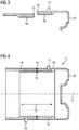
FIG 3 zeigt zwei weitere anders ausgeführte Grundelemente 19, die zusammengesetzt ebenfalls einen Hohlraum schaffen und somit einen Flüssigkeitskühlmantel 5 mit seinem Kühlkanal 15 bilden. Auch hier weist das eine Grundelement 19 Ausgestaltungen auf, die letztlich ein Lagerschild 9 bilden. Das Cold-Spray-Material 14 wird dabei gemäßFIG 4 an den Stoßstellen der beiden Grundelemente 19, die insbesondere V-förmig ausgeführt sind eingetragen. Für den Kontaktbereich 12 ist entscheidend, dass das Cold-Spray-Material 14 auf der Innenseite des Flüssigkeitskühlmantels 5 bündig aufgetragen wird. -
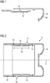
FIG 5 zeigt ein einstückiges Basiselement 6, das ebenfalls ein Lagerschild 9 ausbildet und eine Gussöffnung 7 aufweist, die konstruktionsbedingt verschlossen wird, aber im Herstellungsprozess zunächst notwendig ist, um den Kern des Gusses abzustützen. Der Verschluss dieser Gussöffnung 7 gelingt durch einen Cold-Spray-Materialeintrag 14 oder durch ein nicht näher dargestellten Verschlusselement 8, das in der Gussöffnung 7 vorgesehen wird und das mittels des Cold-Spray-Verfahrens mit dem einstückigen Basiselement 6 verbunden wird. Die Gussöffnung 7 ist gemäßFIG 5 nach innen gerichtet. - Für den Kontaktbereich 12 ist entscheidend, dass das Cold-Spray-Material 14 und/oder das Verschlusselement 8 auf der Innenseite des Flüssigkeitskühlmantels 5 bündig angeordnet wird, um einen funktionsfähigen Schrumpfsitz des Flüssigkeitskühlmantels 5 auf dem Stator 2 zu erhalten.
-
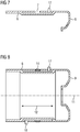
FIG 7 zeigt eine Gussöffnung 7 eines einstückigen Basiselements 6, die nach außen gerichtet ist und dort ebenfalls mittels eines Verschlusselements 8 oder durch einen Cold-Spray-Materialeintrag 14 verschlossen wird. Damit liegen nachFIG 6 undFIG 8 Flüssigkeitskühlmäntel 5 vor, die jeweils nur einen in Umfangsrichtung betrachtet umlaufenden Cold-Spray-Materialeintrag 14 aufweisen. - Unabhängig von der Zusammensetzung des Flüssigkeitskühlmantels 5, d.h. aus einem einstückigen Basiselement 6 oder zwei- oder mehrteiligen Grundelementen 19, wird ein Stator 2 in den Flüssigkeitskühlmantel 5 eingeschrumpft. Somit kommt in dem Kontaktbereich 12 das elektromagnetisch-leitfähige Material des Stators, insbesondere ein Statorblechpaket zum Anliegen, derart dass sich ein vergleichseise guter Wärmeübergang vom Blechpaket des Stators 2 zum Flüssigkeitskühlmantel 5 einstellt.
-
FIG 9 zeigt eine dynamoelektrische Maschine 1 mit einem erfindungsgemäßen Flüssigkeitskühlmantel 5. Über eine Einlassöffnung 17 wird ein Kühlmittel in den Hohlraum bzw. den Kühlkanal 15 eingespeist und über eine Auslassöffnung 18 entnommen. Der Hohlraum kann dabei durch dementsprechende Elemente, wie Stege derart ausgebildet sein, dass sich ein vorgegebener Kühlmittelverlauf innerhalb des Hohlraumes 15 von der Einlassöffnung 17 zur Auslassöffnung 18 einstellt. Dies kann z.B. ein mäandernder Verlauf innerhalb des Hohlraumes 15 oder ein spiralförmiger Verlauf um die Achse 11 sein. - Die Einlassöffnungen 17 und Auslassöffnungen 18 sind dabei entweder bereits an einem Basiselement 6 oder Grundelement 19 vorgesehen oder werden nachträglich an den Flüssigkeitskühlmantel 5 angebracht.
- Der Kühlkreislauf kann dabei auch in ein Kühlkonzept eines Antriebs eines Schienenfahrzeugs, Mining-Trucks oder andere Elektrofahrzeuge eingebunden sein, indem beispielsweise die Wärme über Wärmetauscher zu Heizzwecken innerhalb des Fahrzeuges verwendet wird.
Claims (9)
- Verfahren zur Herstellung eines Flüssigkeitskühlmantels (5) eines Stators (2) einer dynamoelektrischen rotatorischen Maschine (1), insbesondere eines Traktionsantriebs, durch folgende Schritte:- Bereitstellen eines vorgefertigten Basiselements (6) eines Flüssigkeitskühlmantels (5) aus einem Gusswerkstoff, beispielsweise wie GJS (globularer Grauguss)oder Aluminium mit einem ausgebildeten Hohlraum (15), der zumindest eine Einlassöffnung (17), zumindest eine Auslassöffnung (18) und zumindest eine Gussöffnung (7) aufweist,- Entfernen des Gusssandes aus dem Hohlraum (15) des aus dem Gusswerkstoff gebildeten Basiselements (6),- Verschließen der Gussöffnungen (7) mittels eines Cold-Spray-Verfahrens.
- Verfahren nach Anspruch 1, dadurch gekennzeichnet, dass die Gussöffnung (7) mittels eines Verschlusselements (8) geschlossen wird, in dem mittels des Cold-Spray-Verfahrens das Verschlusselement (8) mit dem Basiselement (6) verbunden und damit die Gussöffnung (7) abgedichtet wird.
- Verfahren nach Anspruch 2, dadurch gekennzeichnet, dass das Verschlusselement (8) und die Gussöffnung (7) jeweils Nut, insbesondere eine V-Nut (10) aufweisen, in das Material mittels des Cold-Spray-Verfahren eingebracht wird.
- Verfahren nach Anspruch 1, dadurch gekennzeichnet, dass nach Entfernen des Gusssandes in den ausgebildeten Hohlraum (15) eine aushärtende flüssigkeitslösliche Masse eingebracht wird, gegen die das Cold-Spray-Verfahren sprüht und die Gussöffnung (7) schließt.
- Verfahren nach Anspruch 4, dadurch gekennzeichnet, dass nach Abschluss des Cold-Spray-Verfahrens die flüssigkeitslösliche Masse aus dem Hohlraum (15) des Basiselements (6) über die Einlassöffnung (17) und/oder Auslassöffnung (18) gespült wird.
- Verfahren zur Herstellung eines Flüssigkeitskühlmantels eines Stators (2) einer dynamoelektrischen rotatorischen Maschine (1), insbesondere eines Traktionsantriebs durch folgende Schritte:- Bereitstellen zweier oder mehrerer zusammensetzbarer Grundelemente (19) eines Flüssigkeitskühlmantels (5) aus einem Gusswerkstoff, beispielsweise wie GJS (globularer Grauguss) oder Aluminium, die zusammengesetzt einen ausgebildeten Hohlraum (15) aufweisen,- beim Zusammensetzen der Grundelemente (19) werden die Nahtstellen und/oder Stoßkanten mittels eines Cold-Spray-Verfahrens abgedichtet und fixiert.
- Stator (2) einer dynamoelektrischen rotatorischen Maschine (1) mit einem Flüssigkeitskühlmantel (5) nach einem der vorhergehenden Ansprüche 1 bis 5 oder 6, dadurch gekennzeichnet, dass der Flüssigkeitskühlmantel (5) auf den Stator (2) aufgeschrumpft ist, wobei ein thermisch leitend Kontaktbereich (12) des Flüssigkeitsmantels (5) mit dem Stator (2) vorhanden ist.
- Dynamoelektrische rotatorische Maschine (1) mit einem Stator (2) nach Anspruch 7.
- Schienenfahrzeug, Mining-Trucks oder andere Elektrofahrzeuge mit zumindest einer dynamoelektrischen rotatorischen Maschine (1) nach Anspruch 8.
Priority Applications (3)
| Application Number | Priority Date | Filing Date | Title |
|---|---|---|---|
| EP18193980.2A EP3624312B1 (de) | 2018-09-12 | 2018-09-12 | Verfahren zur herstellung eines flüssigkeitskühlmantels |
| PCT/EP2019/073419 WO2020053028A1 (de) | 2018-09-12 | 2019-09-03 | Verfahren zur herstellung eines flüssigkeitskühlmantels |
| CN201980067215.6A CN112889204A (zh) | 2018-09-12 | 2019-09-03 | 用于制造液体冷却套的方法 |
Applications Claiming Priority (1)
| Application Number | Priority Date | Filing Date | Title |
|---|---|---|---|
| EP18193980.2A EP3624312B1 (de) | 2018-09-12 | 2018-09-12 | Verfahren zur herstellung eines flüssigkeitskühlmantels |
Publications (2)
| Publication Number | Publication Date |
|---|---|
| EP3624312A1 true EP3624312A1 (de) | 2020-03-18 |
| EP3624312B1 EP3624312B1 (de) | 2021-08-11 |
Family
ID=63579032
Family Applications (1)
| Application Number | Title | Priority Date | Filing Date |
|---|---|---|---|
| EP18193980.2A Active EP3624312B1 (de) | 2018-09-12 | 2018-09-12 | Verfahren zur herstellung eines flüssigkeitskühlmantels |
Country Status (3)
| Country | Link |
|---|---|
| EP (1) | EP3624312B1 (de) |
| CN (1) | CN112889204A (de) |
| WO (1) | WO2020053028A1 (de) |
Citations (6)
| Publication number | Priority date | Publication date | Assignee | Title |
|---|---|---|---|---|
| JP2860036B2 (ja) * | 1993-03-10 | 1999-02-24 | 株式会社日立製作所 | 外被冷却形回転電機 |
| DE102004050645B4 (de) | 2004-10-18 | 2006-09-07 | Siemens Ag | Gehäuse einer elektrischen Maschine mit in einer Gehäusewand verlaufenden Kühlkanälen |
| WO2011066981A2 (de) * | 2009-12-04 | 2011-06-09 | Dietermann Gmbh & Co. Kg | Doppelwandiger gusskörper für eine flüssigkeitsgekühlte elektrische maschine |
| JP2014108006A (ja) * | 2012-11-29 | 2014-06-09 | Toyota Industries Corp | 回転子、その回転子を備える誘導電動機、及び回転子の製造方法 |
| DE102016203945A1 (de) * | 2016-03-10 | 2017-09-14 | Siemens Aktiengesellschaft | Statoreinrichtung für eine elektrische Maschine und Verfahren zu deren Herstellung |
| DE112015006496T5 (de) * | 2015-04-27 | 2018-01-18 | Mitsubishi Electric Corporation | Rotierende elektrische Maschine |
Family Cites Families (13)
| Publication number | Priority date | Publication date | Assignee | Title |
|---|---|---|---|---|
| DE19916459A1 (de) * | 1999-04-12 | 2000-10-26 | Bosch Gmbh Robert | Starter-Generator für ein Kraftfahrzeug |
| DE102005056280A1 (de) * | 2005-11-24 | 2007-05-31 | R.A.E.-Gmbh | Gegossene hohle Kurbelwelle |
| JP2008274352A (ja) * | 2007-04-27 | 2008-11-13 | Ihi Corp | 封止補完方法、金属部材補修方法、金属欠陥補修装置 |
| US7800259B2 (en) * | 2007-05-10 | 2010-09-21 | Gm Global Technology Operations, Inc. | Stator assembly for use in a fluid-cooled motor and method of making the same |
| DE102008011258A1 (de) * | 2008-02-27 | 2009-09-10 | Continental Automotive Gmbh | Gekühltes Gehäuse bestehend aus einem Turbinengehäuse und einem Lagergehäuse eines Turboladers |
| DE102009038691A1 (de) * | 2009-08-24 | 2011-03-03 | Siemens Aktiengesellschaft | Elektrische Maschine |
| EP2479874A1 (de) * | 2011-01-24 | 2012-07-25 | Siemens Aktiengesellschaft | Kühlmantel mit mäanderförmigem Kühlsystem |
| DE102012016208A1 (de) * | 2012-08-16 | 2014-02-20 | Volkswagen Aktiengesellschaft | Aggregat und Gehäuse mit einem Kühlmantel |
| DE102013211408B4 (de) * | 2013-06-18 | 2022-10-27 | Schaeffler Technologies AG & Co. KG | Kühleinrichtung zur Kühlung einer elektrischen Maschine und entsprechende elektrische Maschine mit Kühleinrichtung |
| EP3338348B1 (de) * | 2015-08-19 | 2020-07-22 | TM4 Inc. | Eingegossene kühlanordnung für elektrische maschinen |
| DE102015221777A1 (de) * | 2015-11-05 | 2017-05-11 | Volkswagen Aktiengesellschaft | Gehäuseanordnung für eine elektrische Maschine |
| DE102016200186B4 (de) * | 2016-01-11 | 2026-04-30 | Bayerische Motoren Werke Aktiengesellschaft | Elektrische Maschine |
| JP2018087609A (ja) * | 2016-11-29 | 2018-06-07 | 東京電力ホールディングス株式会社 | 配管補修方法 |
-
2018
- 2018-09-12 EP EP18193980.2A patent/EP3624312B1/de active Active
-
2019
- 2019-09-03 CN CN201980067215.6A patent/CN112889204A/zh active Pending
- 2019-09-03 WO PCT/EP2019/073419 patent/WO2020053028A1/de not_active Ceased
Patent Citations (6)
| Publication number | Priority date | Publication date | Assignee | Title |
|---|---|---|---|---|
| JP2860036B2 (ja) * | 1993-03-10 | 1999-02-24 | 株式会社日立製作所 | 外被冷却形回転電機 |
| DE102004050645B4 (de) | 2004-10-18 | 2006-09-07 | Siemens Ag | Gehäuse einer elektrischen Maschine mit in einer Gehäusewand verlaufenden Kühlkanälen |
| WO2011066981A2 (de) * | 2009-12-04 | 2011-06-09 | Dietermann Gmbh & Co. Kg | Doppelwandiger gusskörper für eine flüssigkeitsgekühlte elektrische maschine |
| JP2014108006A (ja) * | 2012-11-29 | 2014-06-09 | Toyota Industries Corp | 回転子、その回転子を備える誘導電動機、及び回転子の製造方法 |
| DE112015006496T5 (de) * | 2015-04-27 | 2018-01-18 | Mitsubishi Electric Corporation | Rotierende elektrische Maschine |
| DE102016203945A1 (de) * | 2016-03-10 | 2017-09-14 | Siemens Aktiengesellschaft | Statoreinrichtung für eine elektrische Maschine und Verfahren zu deren Herstellung |
Also Published As
| Publication number | Publication date |
|---|---|
| EP3624312B1 (de) | 2021-08-11 |
| CN112889204A (zh) | 2021-06-01 |
| WO2020053028A1 (de) | 2020-03-19 |
Similar Documents
| Publication | Publication Date | Title |
|---|---|---|
| EP2953245B1 (de) | Käfigläufer einer asynchronmaschine | |
| DE102020117267B4 (de) | Statoranordnung mit Kühlung | |
| EP3289669B1 (de) | Gehäuselose elektrische maschine | |
| EP3373421B1 (de) | Gehäuseeinheit für eine elektrische maschine | |
| EP2978108B1 (de) | Kühlmantel für eine elektrische maschine und verfahren zur montage des kühlmantels sowie eine mit einem kühlmantel ausgestattete elektrische maschine | |
| EP3741031B1 (de) | Verfahren zur herstellung eines käfigläufers | |
| DE102017102141A1 (de) | Verfahren zur Herstellung einer elektrischen Antriebsmaschine und elektrische Antriebsmaschine | |
| EP3317946B1 (de) | Elektrische maschine mit kopplungen im kühlsystem | |
| DE102016203945A1 (de) | Statoreinrichtung für eine elektrische Maschine und Verfahren zu deren Herstellung | |
| DE112015006260T5 (de) | Rotor für eine elektrische Rotationsmaschine und Herstellungsverfahren für einen Rotor einer elektrischen Rotationsmaschine | |
| EP0858692A1 (de) | Flüssigkeitskühlung für elektrische maschinen | |
| WO2023217471A1 (de) | Rotor für eine elektrische traktionsmaschine eines kraftfahrzeugs sowie elektrische traktionsmaschine | |
| DE102022213027A1 (de) | Rotor und elektrische Maschine | |
| DE102020117266A1 (de) | Statoranordnung für eine Elektromaschine | |
| DE102015224577A1 (de) | Rotor, Verfahren zum Herstellen eines Rotors, Asynchronmaschine und Fahrzeug | |
| DE102015016584A1 (de) | Verfahren zum Herstellen eines Stators und Stator | |
| EP3577746B1 (de) | Herstellung eines rotors mittels additiver fertigung | |
| DE102021130498A1 (de) | Statorblechpaket für einen Stator einer elektrischen Antriebsmaschine | |
| EP3629452A1 (de) | Verfahren zur herstellung eines rotors für eine elektrische rotierende maschine | |
| EP3179604B1 (de) | Reluktanzläufer einer synchronen reluktanzmaschine | |
| DE102021115421B3 (de) | Verfahren und Vorrichtung zur Herstellung einer Statoreinrichtung für eine elektrische Maschine, insbesondere für eine Antriebsmaschine eines Elektrofahrzeugs | |
| DE102017217387A1 (de) | Gussbauteil mit eingegossenem Rohr und Verfahren zur Herstellung | |
| EP3624312B1 (de) | Verfahren zur herstellung eines flüssigkeitskühlmantels | |
| DE102015221776A1 (de) | Gehäuseanordnung für eine elektrische Maschine | |
| WO2021219475A1 (de) | Elektrische maschine und verfahren zu deren herstellung |
Legal Events
| Date | Code | Title | Description |
|---|---|---|---|
| PUAI | Public reference made under article 153(3) epc to a published international application that has entered the european phase |
Free format text: ORIGINAL CODE: 0009012 |
|
| STAA | Information on the status of an ep patent application or granted ep patent |
Free format text: STATUS: THE APPLICATION HAS BEEN PUBLISHED |
|
| AK | Designated contracting states |
Kind code of ref document: A1 Designated state(s): AL AT BE BG CH CY CZ DE DK EE ES FI FR GB GR HR HU IE IS IT LI LT LU LV MC MK MT NL NO PL PT RO RS SE SI SK SM TR |
|
| AX | Request for extension of the european patent |
Extension state: BA ME |
|
| STAA | Information on the status of an ep patent application or granted ep patent |
Free format text: STATUS: REQUEST FOR EXAMINATION WAS MADE |
|
| 17P | Request for examination filed |
Effective date: 20200916 |
|
| RBV | Designated contracting states (corrected) |
Designated state(s): AL AT BE BG CH CY CZ DE DK EE ES FI FR GB GR HR HU IE IS IT LI LT LU LV MC MK MT NL NO PL PT RO RS SE SI SK SM TR |
|
| GRAP | Despatch of communication of intention to grant a patent |
Free format text: ORIGINAL CODE: EPIDOSNIGR1 |
|
| STAA | Information on the status of an ep patent application or granted ep patent |
Free format text: STATUS: GRANT OF PATENT IS INTENDED |
|
| INTG | Intention to grant announced |
Effective date: 20210323 |
|
| GRAS | Grant fee paid |
Free format text: ORIGINAL CODE: EPIDOSNIGR3 |
|
| GRAA | (expected) grant |
Free format text: ORIGINAL CODE: 0009210 |
|
| STAA | Information on the status of an ep patent application or granted ep patent |
Free format text: STATUS: THE PATENT HAS BEEN GRANTED |
|
| AK | Designated contracting states |
Kind code of ref document: B1 Designated state(s): AL AT BE BG CH CY CZ DE DK EE ES FI FR GB GR HR HU IE IS IT LI LT LU LV MC MK MT NL NO PL PT RO RS SE SI SK SM TR |
|
| REG | Reference to a national code |
Ref country code: CH Ref legal event code: EP |
|
| REG | Reference to a national code |
Ref country code: DE Ref legal event code: R096 Ref document number: 502018006509 Country of ref document: DE |
|
| REG | Reference to a national code |
Ref country code: IE Ref legal event code: FG4D Free format text: LANGUAGE OF EP DOCUMENT: GERMAN Ref country code: AT Ref legal event code: REF Ref document number: 1420398 Country of ref document: AT Kind code of ref document: T Effective date: 20210915 |
|
| REG | Reference to a national code |
Ref country code: LT Ref legal event code: MG9D |
|
| REG | Reference to a national code |
Ref country code: NL Ref legal event code: MP Effective date: 20210811 |
|
| PG25 | Lapsed in a contracting state [announced via postgrant information from national office to epo] |
Ref country code: NO Free format text: LAPSE BECAUSE OF FAILURE TO SUBMIT A TRANSLATION OF THE DESCRIPTION OR TO PAY THE FEE WITHIN THE PRESCRIBED TIME-LIMIT Effective date: 20211111 Ref country code: PT Free format text: LAPSE BECAUSE OF FAILURE TO SUBMIT A TRANSLATION OF THE DESCRIPTION OR TO PAY THE FEE WITHIN THE PRESCRIBED TIME-LIMIT Effective date: 20211213 Ref country code: LT Free format text: LAPSE BECAUSE OF FAILURE TO SUBMIT A TRANSLATION OF THE DESCRIPTION OR TO PAY THE FEE WITHIN THE PRESCRIBED TIME-LIMIT Effective date: 20210811 Ref country code: BG Free format text: LAPSE BECAUSE OF FAILURE TO SUBMIT A TRANSLATION OF THE DESCRIPTION OR TO PAY THE FEE WITHIN THE PRESCRIBED TIME-LIMIT Effective date: 20211111 Ref country code: SE Free format text: LAPSE BECAUSE OF FAILURE TO SUBMIT A TRANSLATION OF THE DESCRIPTION OR TO PAY THE FEE WITHIN THE PRESCRIBED TIME-LIMIT Effective date: 20210811 Ref country code: RS Free format text: LAPSE BECAUSE OF FAILURE TO SUBMIT A TRANSLATION OF THE DESCRIPTION OR TO PAY THE FEE WITHIN THE PRESCRIBED TIME-LIMIT Effective date: 20210811 Ref country code: HR Free format text: LAPSE BECAUSE OF FAILURE TO SUBMIT A TRANSLATION OF THE DESCRIPTION OR TO PAY THE FEE WITHIN THE PRESCRIBED TIME-LIMIT Effective date: 20210811 Ref country code: FI Free format text: LAPSE BECAUSE OF FAILURE TO SUBMIT A TRANSLATION OF THE DESCRIPTION OR TO PAY THE FEE WITHIN THE PRESCRIBED TIME-LIMIT Effective date: 20210811 Ref country code: ES Free format text: LAPSE BECAUSE OF FAILURE TO SUBMIT A TRANSLATION OF THE DESCRIPTION OR TO PAY THE FEE WITHIN THE PRESCRIBED TIME-LIMIT Effective date: 20210811 |
|
| PG25 | Lapsed in a contracting state [announced via postgrant information from national office to epo] |
Ref country code: PL Free format text: LAPSE BECAUSE OF FAILURE TO SUBMIT A TRANSLATION OF THE DESCRIPTION OR TO PAY THE FEE WITHIN THE PRESCRIBED TIME-LIMIT Effective date: 20210811 Ref country code: LV Free format text: LAPSE BECAUSE OF FAILURE TO SUBMIT A TRANSLATION OF THE DESCRIPTION OR TO PAY THE FEE WITHIN THE PRESCRIBED TIME-LIMIT Effective date: 20210811 Ref country code: GR Free format text: LAPSE BECAUSE OF FAILURE TO SUBMIT A TRANSLATION OF THE DESCRIPTION OR TO PAY THE FEE WITHIN THE PRESCRIBED TIME-LIMIT Effective date: 20211112 |
|
| PG25 | Lapsed in a contracting state [announced via postgrant information from national office to epo] |
Ref country code: NL Free format text: LAPSE BECAUSE OF FAILURE TO SUBMIT A TRANSLATION OF THE DESCRIPTION OR TO PAY THE FEE WITHIN THE PRESCRIBED TIME-LIMIT Effective date: 20210811 |
|
| PG25 | Lapsed in a contracting state [announced via postgrant information from national office to epo] |
Ref country code: DK Free format text: LAPSE BECAUSE OF FAILURE TO SUBMIT A TRANSLATION OF THE DESCRIPTION OR TO PAY THE FEE WITHIN THE PRESCRIBED TIME-LIMIT Effective date: 20210811 |
|
| REG | Reference to a national code |
Ref country code: CH Ref legal event code: PL |
|
| REG | Reference to a national code |
Ref country code: DE Ref legal event code: R097 Ref document number: 502018006509 Country of ref document: DE |
|
| REG | Reference to a national code |
Ref country code: BE Ref legal event code: MM Effective date: 20210930 |
|
| PG25 | Lapsed in a contracting state [announced via postgrant information from national office to epo] |
Ref country code: SM Free format text: LAPSE BECAUSE OF FAILURE TO SUBMIT A TRANSLATION OF THE DESCRIPTION OR TO PAY THE FEE WITHIN THE PRESCRIBED TIME-LIMIT Effective date: 20210811 Ref country code: SK Free format text: LAPSE BECAUSE OF FAILURE TO SUBMIT A TRANSLATION OF THE DESCRIPTION OR TO PAY THE FEE WITHIN THE PRESCRIBED TIME-LIMIT Effective date: 20210811 Ref country code: RO Free format text: LAPSE BECAUSE OF FAILURE TO SUBMIT A TRANSLATION OF THE DESCRIPTION OR TO PAY THE FEE WITHIN THE PRESCRIBED TIME-LIMIT Effective date: 20210811 Ref country code: MC Free format text: LAPSE BECAUSE OF FAILURE TO SUBMIT A TRANSLATION OF THE DESCRIPTION OR TO PAY THE FEE WITHIN THE PRESCRIBED TIME-LIMIT Effective date: 20210811 Ref country code: EE Free format text: LAPSE BECAUSE OF FAILURE TO SUBMIT A TRANSLATION OF THE DESCRIPTION OR TO PAY THE FEE WITHIN THE PRESCRIBED TIME-LIMIT Effective date: 20210811 Ref country code: CZ Free format text: LAPSE BECAUSE OF FAILURE TO SUBMIT A TRANSLATION OF THE DESCRIPTION OR TO PAY THE FEE WITHIN THE PRESCRIBED TIME-LIMIT Effective date: 20210811 Ref country code: AL Free format text: LAPSE BECAUSE OF FAILURE TO SUBMIT A TRANSLATION OF THE DESCRIPTION OR TO PAY THE FEE WITHIN THE PRESCRIBED TIME-LIMIT Effective date: 20210811 |
|
| PLBE | No opposition filed within time limit |
Free format text: ORIGINAL CODE: 0009261 |
|
| STAA | Information on the status of an ep patent application or granted ep patent |
Free format text: STATUS: NO OPPOSITION FILED WITHIN TIME LIMIT |
|
| 26N | No opposition filed |
Effective date: 20220512 |
|
| PG25 | Lapsed in a contracting state [announced via postgrant information from national office to epo] |
Ref country code: LU Free format text: LAPSE BECAUSE OF NON-PAYMENT OF DUE FEES Effective date: 20210912 Ref country code: IT Free format text: LAPSE BECAUSE OF FAILURE TO SUBMIT A TRANSLATION OF THE DESCRIPTION OR TO PAY THE FEE WITHIN THE PRESCRIBED TIME-LIMIT Effective date: 20210811 Ref country code: IE Free format text: LAPSE BECAUSE OF NON-PAYMENT OF DUE FEES Effective date: 20210912 Ref country code: BE Free format text: LAPSE BECAUSE OF NON-PAYMENT OF DUE FEES Effective date: 20210930 |
|
| PG25 | Lapsed in a contracting state [announced via postgrant information from national office to epo] |
Ref country code: SI Free format text: LAPSE BECAUSE OF FAILURE TO SUBMIT A TRANSLATION OF THE DESCRIPTION OR TO PAY THE FEE WITHIN THE PRESCRIBED TIME-LIMIT Effective date: 20210811 Ref country code: LI Free format text: LAPSE BECAUSE OF NON-PAYMENT OF DUE FEES Effective date: 20210930 Ref country code: CH Free format text: LAPSE BECAUSE OF NON-PAYMENT OF DUE FEES Effective date: 20210930 |
|
| PG25 | Lapsed in a contracting state [announced via postgrant information from national office to epo] |
Ref country code: CY Free format text: LAPSE BECAUSE OF FAILURE TO SUBMIT A TRANSLATION OF THE DESCRIPTION OR TO PAY THE FEE WITHIN THE PRESCRIBED TIME-LIMIT Effective date: 20210811 |
|
| PG25 | Lapsed in a contracting state [announced via postgrant information from national office to epo] |
Ref country code: HU Free format text: LAPSE BECAUSE OF FAILURE TO SUBMIT A TRANSLATION OF THE DESCRIPTION OR TO PAY THE FEE WITHIN THE PRESCRIBED TIME-LIMIT; INVALID AB INITIO Effective date: 20180912 |
|
| PG25 | Lapsed in a contracting state [announced via postgrant information from national office to epo] |
Ref country code: MK Free format text: LAPSE BECAUSE OF FAILURE TO SUBMIT A TRANSLATION OF THE DESCRIPTION OR TO PAY THE FEE WITHIN THE PRESCRIBED TIME-LIMIT Effective date: 20210811 |
|
| PG25 | Lapsed in a contracting state [announced via postgrant information from national office to epo] |
Ref country code: TR Free format text: LAPSE BECAUSE OF FAILURE TO SUBMIT A TRANSLATION OF THE DESCRIPTION OR TO PAY THE FEE WITHIN THE PRESCRIBED TIME-LIMIT Effective date: 20210811 |
|
| PG25 | Lapsed in a contracting state [announced via postgrant information from national office to epo] |
Ref country code: MT Free format text: LAPSE BECAUSE OF FAILURE TO SUBMIT A TRANSLATION OF THE DESCRIPTION OR TO PAY THE FEE WITHIN THE PRESCRIBED TIME-LIMIT Effective date: 20210811 |
|
| REG | Reference to a national code |
Ref country code: DE Ref legal event code: R081 Ref document number: 502018006509 Country of ref document: DE Owner name: SIEMENS MOBILITY GMBH, DE Free format text: FORMER OWNER: SIEMENS MOBILITY GMBH, 81739 MUENCHEN, DE |
|
| PGFP | Annual fee paid to national office [announced via postgrant information from national office to epo] |
Ref country code: FR Payment date: 20250915 Year of fee payment: 8 Ref country code: AT Payment date: 20250818 Year of fee payment: 8 |
|
| PGFP | Annual fee paid to national office [announced via postgrant information from national office to epo] |
Ref country code: DE Payment date: 20251120 Year of fee payment: 8 |
|
| PGFP | Annual fee paid to national office [announced via postgrant information from national office to epo] |
Ref country code: GB Payment date: 20251002 Year of fee payment: 8 |