EP2953245B1 - Käfigläufer einer asynchronmaschine - Google Patents
Käfigläufer einer asynchronmaschine Download PDFInfo
- Publication number
- EP2953245B1 EP2953245B1 EP15168066.7A EP15168066A EP2953245B1 EP 2953245 B1 EP2953245 B1 EP 2953245B1 EP 15168066 A EP15168066 A EP 15168066A EP 2953245 B1 EP2953245 B1 EP 2953245B1
- Authority
- EP
- European Patent Office
- Prior art keywords
- short
- cage rotor
- conductors
- rotor
- conductor
- Prior art date
- Legal status (The legal status is an assumption and is not a legal conclusion. Google has not performed a legal analysis and makes no representation as to the accuracy of the status listed.)
- Active
Links
- 239000004020 conductor Substances 0.000 claims description 64
- 239000000463 material Substances 0.000 claims description 32
- 229910045601 alloy Inorganic materials 0.000 claims description 11
- 239000000956 alloy Substances 0.000 claims description 11
- 239000007787 solid Substances 0.000 claims description 10
- 150000001875 compounds Chemical class 0.000 description 21
- 238000004382 potting Methods 0.000 description 16
- XAGFODPZIPBFFR-UHFFFAOYSA-N aluminium Chemical compound [Al] XAGFODPZIPBFFR-UHFFFAOYSA-N 0.000 description 14
- 229910052782 aluminium Inorganic materials 0.000 description 14
- 229910052802 copper Inorganic materials 0.000 description 14
- 239000010949 copper Substances 0.000 description 14
- RYGMFSIKBFXOCR-UHFFFAOYSA-N Copper Chemical compound [Cu] RYGMFSIKBFXOCR-UHFFFAOYSA-N 0.000 description 13
- 238000000576 coating method Methods 0.000 description 13
- 241000555745 Sciuridae Species 0.000 description 12
- 229910000838 Al alloy Inorganic materials 0.000 description 11
- 239000011248 coating agent Substances 0.000 description 11
- 238000004512 die casting Methods 0.000 description 8
- 238000000034 method Methods 0.000 description 4
- 238000005266 casting Methods 0.000 description 3
- 238000009713 electroplating Methods 0.000 description 3
- 239000000155 melt Substances 0.000 description 3
- 238000005516 engineering process Methods 0.000 description 2
- 230000002093 peripheral effect Effects 0.000 description 2
- 238000005507 spraying Methods 0.000 description 2
- 230000007704 transition Effects 0.000 description 2
- 238000004804 winding Methods 0.000 description 2
- 238000005275 alloying Methods 0.000 description 1
- 230000004323 axial length Effects 0.000 description 1
- 230000015572 biosynthetic process Effects 0.000 description 1
- 238000006243 chemical reaction Methods 0.000 description 1
- 238000010288 cold spraying Methods 0.000 description 1
- 150000001879 copper Chemical class 0.000 description 1
- 230000001419 dependent effect Effects 0.000 description 1
- 230000006866 deterioration Effects 0.000 description 1
- 238000006073 displacement reaction Methods 0.000 description 1
- ZINJLDJMHCUBIP-UHFFFAOYSA-N ethametsulfuron-methyl Chemical compound CCOC1=NC(NC)=NC(NC(=O)NS(=O)(=O)C=2C(=CC=CC=2)C(=O)OC)=N1 ZINJLDJMHCUBIP-UHFFFAOYSA-N 0.000 description 1
- 238000001125 extrusion Methods 0.000 description 1
- 238000010285 flame spraying Methods 0.000 description 1
- 230000006698 induction Effects 0.000 description 1
- 230000003993 interaction Effects 0.000 description 1
- 230000001788 irregular Effects 0.000 description 1
- 238000003475 lamination Methods 0.000 description 1
- 238000004519 manufacturing process Methods 0.000 description 1
- 238000007750 plasma spraying Methods 0.000 description 1
- 238000007747 plating Methods 0.000 description 1
- 230000001373 regressive effect Effects 0.000 description 1
- 238000007789 sealing Methods 0.000 description 1
- 239000000126 substance Substances 0.000 description 1
- 238000007751 thermal spraying Methods 0.000 description 1
- 238000007740 vapor deposition Methods 0.000 description 1
Images


Classifications
-
- H—ELECTRICITY
- H02—GENERATION; CONVERSION OR DISTRIBUTION OF ELECTRIC POWER
- H02K—DYNAMO-ELECTRIC MACHINES
- H02K17/00—Asynchronous induction motors; Asynchronous induction generators
- H02K17/02—Asynchronous induction motors
- H02K17/16—Asynchronous induction motors having rotors with internally short-circuited windings, e.g. cage rotors
- H02K17/165—Asynchronous induction motors having rotors with internally short-circuited windings, e.g. cage rotors characterised by the squirrel-cage or other short-circuited windings
-
- H—ELECTRICITY
- H02—GENERATION; CONVERSION OR DISTRIBUTION OF ELECTRIC POWER
- H02K—DYNAMO-ELECTRIC MACHINES
- H02K15/00—Methods or apparatus specially adapted for manufacturing, assembling, maintaining or repairing of dynamo-electric machines
- H02K15/0012—Manufacturing cage rotors
-
- H—ELECTRICITY
- H02—GENERATION; CONVERSION OR DISTRIBUTION OF ELECTRIC POWER
- H02K—DYNAMO-ELECTRIC MACHINES
- H02K17/00—Asynchronous induction motors; Asynchronous induction generators
- H02K17/02—Asynchronous induction motors
- H02K17/16—Asynchronous induction motors having rotors with internally short-circuited windings, e.g. cage rotors
- H02K17/18—Asynchronous induction motors having rotors with internally short-circuited windings, e.g. cage rotors having double-cage or multiple-cage rotors
-
- H—ELECTRICITY
- H02—GENERATION; CONVERSION OR DISTRIBUTION OF ELECTRIC POWER
- H02K—DYNAMO-ELECTRIC MACHINES
- H02K17/00—Asynchronous induction motors; Asynchronous induction generators
- H02K17/02—Asynchronous induction motors
- H02K17/16—Asynchronous induction motors having rotors with internally short-circuited windings, e.g. cage rotors
- H02K17/20—Asynchronous induction motors having rotors with internally short-circuited windings, e.g. cage rotors having deep-bar rotors
-
- H—ELECTRICITY
- H02—GENERATION; CONVERSION OR DISTRIBUTION OF ELECTRIC POWER
- H02K—DYNAMO-ELECTRIC MACHINES
- H02K3/00—Details of windings
- H02K3/02—Windings characterised by the conductor material
-
- Y—GENERAL TAGGING OF NEW TECHNOLOGICAL DEVELOPMENTS; GENERAL TAGGING OF CROSS-SECTIONAL TECHNOLOGIES SPANNING OVER SEVERAL SECTIONS OF THE IPC; TECHNICAL SUBJECTS COVERED BY FORMER USPC CROSS-REFERENCE ART COLLECTIONS [XRACs] AND DIGESTS
- Y10—TECHNICAL SUBJECTS COVERED BY FORMER USPC
- Y10T—TECHNICAL SUBJECTS COVERED BY FORMER US CLASSIFICATION
- Y10T29/00—Metal working
- Y10T29/49—Method of mechanical manufacture
- Y10T29/49002—Electrical device making
- Y10T29/49014—Superconductor
Definitions
- the invention relates to a squirrel cage rotor asynchronous machine with axially stacked laminated core having substantially axially extending grooves in which an electrical conductor is located, which forms with the electrical conductors in other grooves on the respective end faces of the laminated core shorting rings and so forms a squirrel cage.
- the rotor in particular the short-circuit ring, is a weak point. It comes at the short-circuit ring by the centrifugal forces to irregular widening, which make an impermissible non-regressive changes and in so far as an imbalance in the runner noticeable. This occurs especially with short-circuited rings that use pure aluminum (AL99.5) as the electrically conductive potting compound. Although the electrical conductance is relatively high, but this material is not suitable for high centrifugal force.
- a squirrel-cage rotor of an induction machine in which hollow shaped rods are arranged in grooves of the squirrel-cage rotor.
- the publication US 2014/0139066 A1 describes a rotor with a rotor lamination stack having slits arranged in the axial direction.
- rotor bars are arranged in the slots rotor bars.
- the slots and the rotor bars each comprise in cross-section a plurality of ridges and depressions in at least one of the two end faces in a circumferential direction.
- the publication GB 822 313 A describes an asynchronous motor having a high-output rotor to achieve maximum current displacement during start-up.
- the shape of the rotor bars is designed such that they jam themselves in the grooves.
- the present invention seeks to provide a squirrel cage an asynchronous machine that holds both the centrifugal stresses withstand, as well as comparatively little loss.
- This material is equipped with comparatively good technical properties for die casting by being pourable at comparatively low temperatures.
- the speed suitability of the short-circuit ring is thereby considerably increased, since this potting compound only comes into a plastic range at higher speeds.
- aluminum bars A1 99.7 are used with a conductance of 36m / ohm mm 2 with corresponding groove geometries and a certain groove filling in the groove. For example, 85% of the groove filling by A1 rod and 15% potting compound.
- the comparatively lower conductance in the short-circuit ring can be compensated by increasing the cross-section by a factor of 1.7.
- the inserted copper rod must be designed in a specially designed for high speed geometry, so it does not come to a demolition of the contact surface of the rod to the cast short-circuit ring due to the high tangential stresses.
- This copper rod has special geometries for high speeds and tangential stresses in the short-circuit ring.
- the rod is coated.
- connection between the conductors and the short-circuit rings is improved by the materials forming a mixed-crystalline compound at suitable points.
- the shorting bars project axially out of both ends of the rotor core and into the molded shorting rings.
- the increase in the bonding forces between conductor ends and short-circuiting rings is u.a. achieved in that the sub-conductors - ie the rods of aluminum or copper - are coated such that both between the coating and the conductors an alloy - ie a mixed crystalline compound - arises, as well as between the coating and the cast material of the shorting rings.
- Läufererblechonce can also axially expand again when the connection between the sub-conductors - ie the rods - and the cast shorting rings can not muster sufficient axial holding force.
- the conductors are bonded to the die casting by means of maximum possible bonding forces. Accordingly, the connection between the conductors and the short circuit rings remains stable despite possibly different thermal expansion coefficients, when the squirrel cage passes through pronounced thermal cycles during operation of the dynamoelectric machine. At high speeds, the centrifugal forces acting on the rotor also partly cause violent stresses in the conductor-shorting ring. Furthermore, the alloy achieves an optimum electrical conductance between the materials.
- the coating and the first alloy layer can be produced by electromechanical plating.
- a layer of the coating material is deposited on the rods by electrochemical means.
- the desired mixed-crystalline compound is formed between the rod and the coating material.
- subsequently diecasting material that is to say Al
- the coating melts on the rods and also forms a mixed-crystalline compound with the diecasting melt, so that a second alloying layer is formed.
- thermal spraying in particular flame spraying, plasma spraying, arc spraying or laser spraying, is particularly suitable.
- this layer can be produced by cold spraying or by vapor deposition.
- an oxide layer of the conductors is removed by chemical pretreatment of these conductors prior to coating.
- An oxide layer has insulating electrical properties, so that the removal of said oxide layer significantly reduces the contact resistance between the materials.
- a thin aluminum layer is applied to the surface of the copper conductors in a hybrid rotor with copper rods and aluminum short-circuiting rings. This can be done for example by electroplating. This coating process creates an alloy between the aluminum coating and the copper conductors. Subsequently, an aluminum diecasting compound is injected into the grooves, at the same time as the short-circuiting rings are poured out. Here, the aluminum coating is melted on the surface of the ladder and enters with the molten aluminum a mixed crystalline compound. It will finally formed the second alloy layer.
- the casting process can lead to significant chemical reactions between the coated partial conductors, ie the rods and the melt.
- the coating and the alloy layers can be arranged exclusively on end portions of the conductors projecting out of the rotor core and out into the shorting rings.
- the said end regions represent a critical connection point between the conductors and the short-circuiting rings. Accordingly, here the strong crystalline connection of the materials and sub-conductors involved is particularly important.
- the short-circuit ring on a support ring and thus prevents plastic expansion due to the centrifugal forces at speeds, with peripheral speeds greater than 125 m / s.
- the support ring is made of a material that corresponds in thermal expansion to that of the short-circuit ring to be supported, eg EN AW-7075.
- the support ring can also be obtained from an extrusion material having the required material characteristics.
- high-strength aluminum alloys offer tensile strengths in the range of 500 N / mm 2 .
- These high-strength aluminum alloys with a thermal expansion coefficient of 23.6x10 -6 1 / K correspond to the thermal expansion coefficient of pure aluminum.
- the reduced electrical conductivity of the potting compound is compensated for high rotational speeds by introducing aluminum or copper rods in the groove.
- a high speed suitability of the asynchronous machine is achieved at the same time high conductance in the groove.
- a flow of the potting compound is prevented by interaction of the support ring.
- the material of the support ring has the same thermal expansion coefficient as the short-circuit ring with high tensile strength.
- a temperature range of -40 ° C to + 250 ° C of the dynamoelectric machine can be secured.
- Speeds in the range of 200 to 230 m / s peripheral speed can thus be realized for squirrel-cage according to the invention.
- the allowable yield strength of the support ring can thus be used only for the load from the centrifugal force at high speed and is not already “consumed” by the thermal expansion of the shorting ring. Therefore, an aluminum alloy with tensile strength of 540 N / mm 2 is sufficient.
- a high strength aluminum alloy e.g. AL7075 with high tensile strength can thus speed increases compared to conventional arrangements of up to 70% can be achieved, whereby in particular specifications from the automotive industry (motors for electric cars and buses, purely electric and hybrid drives), or covered in the compressor technology.
- FIG. 1 shows a schematic representation of the longitudinal section of a dynamoelectric machine, which is designed as an asynchronous motor, wherein a housing 18, the bearing plates 8 receives a shaft 4 holds on which a rotor or rotor 5 is rotatably connected to its laminated core.
- the rotor or rotor 5 is referred to in the context of this invention as a squirrel cage.
- the shaft 4 rotates about an axis 20.
- a short-circuit ring 6, which connects the axially from the grooves 9 passing conductor of the rotor 5 at the end faces electrically.
- Radially outside the rotor 5 is, spaced by an air gap 19, a stator 2, which has on its end sides winding heads of a winding system 3.
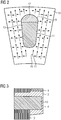
- FIG. 2 shows in a partial cross section of the rotor 5 transverse to an axis 20, two partial conductors, an aluminum rod and a sub-conductor in Nutkopf Suite in aluminum alloy.
- the tangential stress 15 and radial stresses 16 occurring during operation of the asynchronous motor are - as in the following figures - marked with arrows in this section of the rotor 5.
- a contact surface 11 is present between the rotor plate and the conductor bar 13, a contact surface 11 is present.
- FIG. 3 shows in a partial longitudinal section a short-circuit ring 6, a rotor 5 after FIG. 2 , which is supported by a support ring 14 against radial forces - ie centrifugal forces - during operation of the asynchronous motor.
- a sub-conductor 13 - that is, a rod - protrudes axially over the end face of the laminated core 10 of the rotor 5 in the short-circuit ring 6.
- the groove head is also executed there in an aluminum alloy.
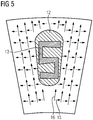
- FIG. 4 and FIG. 5 show in cross-section a short-circuit ring with special bars, ie sub-conductor 13 for high speed, where also there the radial and tangential voltages are indicated by arrows.
- the conductor bar 13 is after FIG. 4 comb-like and after FIG. 5 S-shaped designed to provide the largest possible contact surface of the rod contour within the short-circuit ring 6.
- the conductor bars or sub-conductors 13 are designed comb-like or S-shaped over their entire axial length.
- sub-conductors 13 only partially,
- comb-like, double comb-like, gear-shaped, star-shaped or S-shaped are executed.
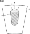
- FIG. 6 shows a partial cross section of a groove 9, which is executed in the direction of the air gap 18 through a slot slot 17, wherein the sub-conductor 12 in the Nutkopf Scheme in the groove slot 17 protrudes.
- a leakage inductance sets in which can be advantageous for a converter operation of the dynamoelectric machine.
- the following versions of the squirrel-cage rotor are especially designed for high speeds and are therefore particularly suitable for applications in vehicle technology in e-cars (direct or hybrid drive) and in compressor drives.
- e-cars direct or hybrid drive
- compressor drives are further material combinations of a squirrel cage.
- the Bar has a squirrel cage with bars or sub-conductor 13 of pure Al, a casting material ALSI9Cu3, the Bar at least partially surrounds and with a support ring 14 made of alloy AW7075 a comparatively high conductance at very high speed suitability.
- rod and potting compound have the same coefficient of expansion. The rod connection to the short-circuit ring 6 succeeds particularly well due to the two AL components.
- a squirrel cage rotor with rods or conductor 13 of copper, a casting material ALSI9Cu3, which surrounds the rod at least partially and with a support ring 14 of the alloy AW7075 also has a comparatively high conductance at very high speed suitability.
- special contours of the copper rod are necessary in order to obtain a sufficient rod connection of the copper rods in the cast short-circuit ring 6.
Description
- Die Erfindung betrifft einen Käfigläufer einer Asynchronmaschine mit axial geschichteten Blechpaket, das im wesentlichen axial verlaufende Nuten aufweist, in denen sich ein elektrischer Leiter befindet, der mit den elektrischen Leitern in anderen Nuten an den jeweiligen Stirnseiten des Blechpakets Kurzschlussringe ausbildet und so einen Käfigläufer bildet.
- Bei Asynchronmotoren mit Käfigläufer, die im höheren Drehzahlbereich eingesetzt werden, zeigt sich am Rotor, insbesondere der Kurzschlussring als Schwachstelle. Dabei kommt es am Kurzschlussring durch die Fliehkräfte zu unregelmäßigen Aufweitungen, die sich zu einer unzulässigen nicht rückbildenden Änderungen und insofern als Unwucht im Läufer bemerkbar machen. Dies tritt vor allem bei Kurzschlussringen auf, die als elektrisch leitende Vergussmasse reines Aluminium (AL99,5) verwenden. Dabei ist zwar der elektrische Leitwert vergleichsweise hoch, jedoch ist dieses Material nicht für hohe Fliehkraftbeanspruchung geeignet.
- Aus der
DE 10 2005 030 797 A1 ist ein Käfigläufer einer Induktionsmaschine bekannt, wobei hohle Formstäbe in Nuten des Käfigläufers angeordnet werden. - Die Offenlegungsschrift
US 2014/0139066 A1 beschreibt einen Rotor mit einem Rotorblechpaket, das in axiale Richtung angeordnete Schlitze aufweist. In den Schlitzen sind Läuferstäbe angeordnet. Die Schlitze und die Rotorstäbe umfassen jeweils im Querschnitt eine Mehrzahl von Erhöhungen und Vertiefungen in mindestens einer der beiden Stirnflächen in einer Umfangsrichtung. - Die Offenlegungsschrift
GB 822 313 A - Ausgehend davon liegt der Erfindung die Aufgabe zugrunde, einen Käfigläufer einer Asynchronmaschine zu schaffen, die sowohl den Fliehkraftbeanspruchungen Stand hält, als auch vergleichsweise wenig Verluste aufweist.
- Die Lösung der gestellten Aufgabe gelingt durch einen Käfigläufer einer Asynchronmaschine mit
- einem axial geschichteten Blechpaket, mit im Wesentlichen axial verlaufenden Nuten, in denen sich zumindest ein elektrischer Leiter befindet, der sich zumindest aus zwei unterschiedlichen elektrisch leitfähigen Materialien zusammensetzt,
- einem an der jeweiligen Stirnseite des Blechpakets vorgesehenen Kurzschlussring, der die axial aus dem Blechpaket ragenden elektrischen Leiter miteinander elektrisch leitend verbindet,
- wobei das hochfestere Material der unterschiedlichen elektrisch leitfähigen Materialien im axialen Verlauf der jeweiligen Nut betrachtet zumindest abschnittsweise dem radial äußeren Bereich der Nut zugewandt ist,
- Die Lösung der gestellten Aufgabe gelingt auch durch eine Asynchronmaschine mit einem derartigen Käfigläufer, der auf einer Welle drehfest verbunden ist.
- Weiterhin gelingt die Lösung der Aufgabe durch einen Fahrzeugantrieb oder einen Kompressorantrieb mit einem derartigen Käfigläufer.
- Vorteilhafte Ausgestaltungen der Erfindung werden in den abhängigen Ansprüchen erläutert.
- Erfindungsgemäß wird nunmehr eine Aluminiumlegierung verwendet, insbesondere A19Cu3 oder ALSi9Cu3 mit Rm=240 N/mm2 und Rp0,2 = 140 N/ mm2 mit einem Leitwert von nur 21 m/Ohm mm2. Dieses Material ist mit vergleichsweise guten technischen Eigenschaften für Druckgießverfahren ausgestattet, indem es bei vergleichsweise geringen Temperaturen gießfähig ist.
- Des Weiteren wird dadurch die Drehzahltauglichkeit des Kurzschlussrings erheblich erhöht, da diese Vergussmasse erst bei höheren Drehzahlen in einen plastischen Bereich kommt. Um den geringen Leitwert in der Nut auszugleichen, werden erfindungsgemäß Aluminiumstäbe A1 99,7 mit einem Leitwert von 36m/ Ohm mm2 mit dementsprechenden Nutgeometrien und einer gewissen Nutfüllung in die Nut eingesetzt. Zum Beispiel 85% der Nutfüllung durch A1-Stab und 15% Vergussmasse. Der vergleichsweise geringere Leitwert im Kurzschlussring kann durch Querschnittsvergrößerung um einen Faktor von 1,7 ausgeglichen werden.
- Beim Eingießen kommt es zwischen Stab und der Vergussmasse zu einer Legierung, die in der zulässigen Dehnfähigkeit mindestens der der Vergussmasse entspricht. Eine Kontaktfläche, die aufgrund einer Aufweitung bei hohen Drehzahlen senkrecht zu den Tangentialspannungen verläuft, reißt somit nicht ab. Die Ausdehnungskoeffizienten der Aluminiumstäbe und der Vergussmasse sind nahezu identisch. Das System ist somit für hohe Drehzahlen geeignet.
- Bei einer Nutfüllung von ca. 40% mit speziellem Kupferstab und 60% Vergussmasse Al9Cu3 ergibt sich in der Nut ein Leitwert von ca. 35m/Ohm mm2. Der geringere Leitwert im Kurzschlussring kann auch hierbei mittels einer Querschnittsvergrößerung des leitenden Kurzschlussringes um den Faktor 1,7 ausgeglichen werden.
- Der eingelegte Kupferstab muss jedoch in eine für hohe Drehzahl speziell entwickelte Geometrie ausgeführt sein, damit es aufgrund der hohen Tangentialspannungen, nicht zu einem Abriss der Kontaktfläche des Stabes zum gegossenen Kurzschlussring kommt. Dieser Kupferstab weist spezielle Geometrien für hohe Drehzahlen und Tangentialspannungen im Kurzschlussring auf.
- Damit sich zwischen Stab und Vergussmasse eine intermetallische Phase ausbilden kann, wird der Stab beschichtet.
- Bei der Bildung, Herstellung. Geometrien und Verhalten der intermetallischen Phasen wird explizit auch auf die Offenbarung in der
DE 10 2009 008 440 B3 verwiesen, die hiermit auch aufgenommen werden soll. - Die Verbindung zwischen den Leitern und den Kurzschlussringen wird verbessert indem die Materialien an geeigneten Stellen eine mischkristalline Verbindung eingehen. Die Kurzschlussstäbe ragen an beiden stirnseitigen Enden des Läuferblechpakets axial aus diesem heraus und in die gegossenen Kurzschlussringe hinein.
- Die Erhöhung der Bindungskräfte zwischen Leiterenden und Kurzschlussringen wird u.a. dadurch erreicht, dass die Teilleiter - also die Stäbe aus Aluminium oder Kupfer - derartig beschichtet werden, dass sowohl zwischen der Beschichtung und den Leitern eine Legierung - also eine mischkristalline Verbindung - entsteht, als auch zwischen der Beschichtung und dem gegossenen Material der Kurzschlussringe.
- Bei einer Erwärmung des Käfigläufers im Betrieb werden Temperaturen von ca. 200 bis 250°C erreicht. Dadurch kommt es zu einer hohen Wärmeausdehnung in den ausgegossenen Nutbereichen. Der Übergang zwischen den Leitern und den Kurzschlussringen kann sich dabei lösen, wodurch es zu einer Verschlechterung des elektrischen Leitwertes im Bereich des Übergangs zwischen den Kurzschlussringen und den Leitern kommt. Dies führt zu Übergangswiderständen, die den Kurzschlussring zusätzlich aufheizen.
- Das im Druckgussverfahren aus Abdichtungsgründen axial zusammengepresste Läuferblechpaket kann sich außerdem axial wieder aufweiten, wenn die Verbindung zwischen den Teilleitern - also den Stäben - und den gegossenen Kurzschlussringen keine ausreichende axiale Haltekraft aufbringen kann.
- Durch die Beschichtung werden die Leiter durch maximal mögliche Bindungskräfte an den Druckguss gebunden. Entsprechend bleibt die Verbindung zwischen den Leitern und den Kurzschlussringen trotz gegebenenfalls unterschiedlicher thermischer Ausdehnungskoeffizienten stabil, wenn der Käfigläufer im Betrieb der dynamoelektrischen Maschine ausgeprägte thermische Zyklen durchfährt. Bei hohen Drehzahlen bewirken auch die auf den Läufer wirkenden Fliehkräfte teils heftige Spannungen in dem Leiter-Kurschlussring gebildet. Weiterhin wird durch die Legierung ein optimaler elektrischer Übergangsleitwert zwischen den Materialien erzielt.
- Die Beschichtung und die erste Legierungsschicht kann durch elektromechanisches Galvanisieren erzeugt werden. Hierbei wird zunächst auf elektrochemischem Wege eine Schicht des Beschichtungsmaterials auf den Stäben abgeschieden. Dabei entsteht bei diesem Prozess zwischen dem Stab und dem Beschichtungsmaterial die gewünschte mischkristalline Verbindung. Wenn anschließend Druckgussmaterial, also Al insbesondere mittels des Druckgussprozesses appliziert wird, schmilzt die Beschichtung auf den Stäben auf und geht mit der Druckgussschmelze ebenfalls eine mischkristalline Verbindung ein, so dass eine zweite Legierungsschicht entsteht.
- Anstelle des Galvanisierens sind andere Beschichtungsverfahren denkbar, die ebenso zu den gewünschten mischkristallinen Verbindungen zwischen den Materialien führen. Dabei ist thermisches Spritzverfahren, insbesondere Flammspritzen, Plasmaspritzen, Lichtbogenspritzen oder Laserspritzen, besonders geeignet.
- Ebenso kann diese Schicht durch Kaltspritzen oder durch Aufdampfen erzeugt werden.
- Bei all diesen Verfahren insbesondere aber auch beim Galvanisieren wird vor dem Beschichten eine Oxidschicht der Leiter durch chemische Vorbehandlung dieser Leiter entfernt. Eine Oxidschicht hat isolierende elektrische Eigenschaften, so dass durch das Entfernen besagter Oxidschicht der Übergangswiderstand zwischen den Materialien deutlich reduziert wird.
- Beispielsweise wird hierbei bei einem Hybridläufer mit Kupferstäben und Aluminiumkurzschlussringen eine dünne Aluminiumschicht auf die Oberfläche der Kupferleiter aufgetragen. Dies kann beispielsweise durch Galvanisieren erfolgen. Bei diesem Beschichtungsprozess entsteht eine Legierung zwischen der Aluminiumbeschichtung und den Kupferleitern. Anschließend wird eine Aluminiumdruckgussmasse in die Nuten eingespritzt, wobei gleichzeitig damit auch die Kurzschlussringe ausgegossen werden. Hierbei wird die Aluminiumbeschichtung an der Oberfläche der Leiter aufgeschmolzen und geht mit der Aluminiumschmelze eine mischkristalline Verbindung ein. Dabei wird schließlich die zweite Legierungsschicht gebildet. Insbesondere im Bereich der Enden der Kupferstäbe, die aus dem Läuferblechpaket heraus und in die Kurzschlussringe hineinragen, entsteht eine äußerst stabile Verbindung zwischen den beiden Materialien, so dass die Festigkeit bezüglich thermischer Zyklen und im Betrieb auftretenden Fliehkräften erhöht wird. Hierbei entsteht eine nahezu ideale elektrische und mechanische Verbindung zwischen den Kurzschlussringen aus Aluminium und den Kupferstäben.
- Bei dem Gussverfahren kann es zu signifikanten chemischen Reaktionen zwischen den beschichteten Teilleitern, also den Stäben und der Schmelze kommen. Um einen zu großen Abtrag von den Stäben durch die mit den Stäben in Berührung stehende Schmelze zu vermeiden, können in vorteilhafter Ausgestaltung der Erfindung die Beschichtung und die Legierungsschichten ausschließlich an aus dem Läuferblechpaket heraus und in die Kurzschlussringe hereinragenden Endbereichen der Leiter angeordnet werden. Die besagten Endbereiche stellen eine kritische Verbindungsstelle zwischen den Leitern und den Kurzschlussringen dar. Entsprechend ist hier die starke kristalline Verbindung der beteiligten Materialien und Teilleiter besonders wichtig.
- Auch ist vor allem in diesem Endbereich jedes Leiters dem elektrischen Übergangsleitwert zwischen den beiden Materialien eine besondere Bedeutung zuzumessen, da hier der Stromfluss von den Leitern auf die Kurzschlussringe übergeht. Hingegen ist auch bei einem mittels Druckguss hergestellten Läufer eine starke kristalline Verbindung der Leiter in den Bereichen innerhalb der Nut weniger wichtig, da hier kein Stromfluss zwischen den Teilleitern zu erwarten ist.
- An der Kontaktfläche von Stab und Vergussmasse bildet sich eine härtere Legierung, z.B. ALCU2, die in der Dehnfähigkeit geringer ist, als die beiden zu verbindenden Partner Kupfer und Vergussmasse jeweils aufweisen. Um nunmehr ein Abreißen des Stabes vom Kurzschlussring bei hoher Drehzahl zu verhindern, sind nunmehr spezielle Konturen im Stab vorgesehen, wodurch Flächen geschaffen wurden, die nahezu gleichgerichtet mit der Richtung der Tangentialspannungen verläuft. Diese Kontaktflächen werden somit auf Scherung beansprucht, zusätzlich ergibt sich aus der Kontur des Stabes ein Formschluss.
- In einer weiteren Ausführungsform weist der Kurzschlussring einen Stützring auf und verhindert somit eine plastische Aufweitung aufgrund der Fliehkräfte bei Drehzahlen, mit Umfangsgeschwindigkeiten größer 125 m/s. Der Stützring wird aus einem Material hergestellt, das in der Wärmeausdehnung dem des zu stützenden Kurzschlussrings entspricht, z.B.
EN AW-7075. Vorzugsweise aus einer Aluminiumlegierung mit sehr hoher Zugfestigkeit. - Der Stützring kann auch aus einem Strangpressmaterial gewonnen werden, das die erforderlichen Materialkennwerte aufweist.
- Hier bieten sich insbesondere hochfeste Aluminiumlegierungen an, die Zugfestigkeiten im Bereich von 500 N/mm2 erreichen. Diese hochfesten Aluminiumlegierungen mit einem Wärmeausdehnungskoeffizient von 23,6x10⁻⁶ 1/K entsprechen dem Wärmeausdehnungskoeffizient des reinen Aluminiums.
- Erfindungsgemäß wird die reduziert elektrische Leitfähigkeit der Vergussmasse für hohe Drehzahlen durch Einbringen von Aluminium- bzw. Kupferstäben in der Nut ausgeglichen. Somit wird eine hohe Drehzahltauglichkeit der Asynchronmaschine bei gleichzeitig hohem Leitwert in der Nut erzielt. Bei besonders hohen Drehzahlen wird durch Zusammenwirken des Stützrings ein Fließen der Vergussmasse verhindert. Das Material des Stützrings hat einen gleichen Wärmeausdehnungskoeffizienten wie der Kurzschlussring bei gleichzeitig hoher Zugfestigkeit. Dadurch kann ein Temperaturbereich von -40°C bis +250°C der dynamoelektrischen Maschine abgesichert werden. Drehzahlen im Bereich von 200 bis 230 m/s Umfangsgeschwindigkeit können damit für erfindungsgemäße Käfigläufer realisiert werden.
- Die zulässige Streckgrenze des Stützrings kann somit nur für die Belastung aus der Fliehkraft bei hoher Drehzahl genutzt werden und wird nicht schon durch die Wärmeausdehnung des Kurzschlussrings "verbraucht". Deshalb ist bereits eine Aluminiumlegierung mit Zugfestigkeit von 540 N/mm2 ausreichend.
- Bei einer hochfesten Aluminiumlegierung, z.B. AL7075 mit hoher Zugfestigkeit können somit Drehzahlsteigerungen gegenüber herkömmlichen Anordnungen von bis zu 70% erzielt werden, wobei damit insbesondere Vorgaben auch aus der Fahrzeugtechnik (Motoren für elektrisch angetriebene Autos und Busse, rein elektrisch und hybride Antriebe), oder in der Kompressorentechnik abgedeckt werden.
- Wird der Kopfbereich der Nuten des Rotors mit Aluminiumlegierung anstatt Al99,5 ausgegossen, wird aufgrund der höheren Festigkeit dieses Materials ein Herausfließen der Vergussmasse aus der Nut verhindert. Es können somit auch nahezu offene, halboffene Nuten oder Nuten mit vergleichsweise schmalem Nutschlitz im Rotorblechpaket vorgesehen werden, die aufgrund der Streuinduktivität dieser Nuten für den Umrichtereinsatz dieser Rotoren geeignet sind
- Die Erfindung sowie weitere vorteilhafte Ausgestaltungen der Erfindung werden anhand der dargestellten Ausführungsbeispielen näher erläutert; dabei zeigen:
- FIG 1
- einen prinzipiellen Längsschnitt durch eine elektrische Maschine,
- FIG 2
- einen Teilquerschnitt eines Rotors,
- FIG 3
- einen Teillängsschnitt eines Rotors,
- FIG 4, FIG 5
- einen Teilquerschnitt eines Rotors,
- FIG 6
- einen Teilquerschnitt des Rotorblechpakets.
-
FIG 1 zeigt in einer prinzipiellen Darstellung den Längsschnitt einer dynamoelektrischen Maschine, die als Asynchronmotor ausgeführt ist, wobei ein Gehäuse 18, das Lagerschilde 8 aufnimmt, eine Welle 4 hält, auf der ein Rotor bzw. Läufer 5 mit seinem Blechpaket drehfest verbunden ist. Der Rotor bzw. Läufer 5 wird im Umfeld dieser Erfindung auch als Käfigläufer bezeichnet. Die Welle 4 dreht sich dabei um eine Achse 20. An den Stirnseiten dieses Blechpakets befindet sich jeweils ein Kurzschlussring 6, der die axial aus den Nuten 9 tretenden Leiter des Rotors 5 an den Stirnseiten elektrisch verbindet. Radial außerhalb des Rotors 5 befindet sich, beabstandet durch einen Luftspalt 19, ein Stator 2, der an seinen Stirnseiten Wickelköpfe eines Wicklungssystems 3 aufweist. -
FIG 2 zeigt in einem Teilquerschnitts des Rotors 5 quer zu einer Achse 20 zwei Teilleiter, einen Stab aus Aluminium und einen Teilleiter im Nutkopfbereich in Aluminiumlegierung. Die im Betrieb des Asynchronmotors auftretenden Tangentialspannung 15 und Radialspannungen 16 sind - wie auch in den folgenden Figuren - in diesem Abschnitt des Rotors 5 mit Pfeilen gekennzeichnet. Zwischen dem Rotorblech und dem Leiterstab 13 ist eine Kontaktfläche 11 vorhanden. -
FIG 3 zeigt in einem Teillängsschnitt einen Kurzschlussring 6, eines Rotors 5 nachFIG 2 , der durch einen Stützring 14 gegenüber radialen Kräften - also Fliehkräften - im Betrieb des Asynchronmotors abgestützt ist. Ein Teilleiter 13 - also ein Stab - ragt axial über die Stirnfläche des Blechpakets 10 des Rotors 5 in den Kurzschlussring 6. Der Nutkopf ist auch dort in einer Aluminiumlegierung ausgeführt. -
FIG 4 undFIG 5 zeigen im Querschnitt einen Kurzschlussring mit speziellen Stäben, d.h. Teilleiter 13 für Hochdrehzahl, wobei auch dort die radialen und tangentialen Spannungen durch Pfeile gekennzeichnet sind. Der Leiterstab 13 ist nachFIG 4 kammartig und nachFIG 5 S-förmig ausgeführt, um eine möglichst große Kontaktfläche der Stabkontur innerhalb des Kurzschlussringes 6 zu schaffen. Dabei sind die Leiterstäbe bzw. Teilleiter 13 über ihre gesamte axiale Länge kammartig oder S-förmig ausgeführt. Es sind aber auch Ausführungen möglich, bei denen die Teilleiter 13 lediglich abschnittsweise, also beispielsweise nur im Bereich der Kurzschlussringe mit vergrößerter Kontaktfläche, also z.B. kammartig, doppelkammartig, zahnradförmig, sternförmig oder S-förmig ausgeführt sind. - Grundsätzlich sind auch andere oberflächenvergrößernde Formgebungen der Teilleiter 13 möglich, entscheidend ist u.a., ob durch die Oberflächenvergrößerung die angestrebte Kontaktierung der Teilleiter 13 im Kurzschlussring 6 erreicht wird.
-
FIG 6 zeigt einen Teilquerschnitt einer Nut 9, die in Richtung des Luftspalts 18 durch einen Nutschlitz 17 ausgeführt ist, wobei der Teilleiter 12 im Nutkopfbereich in den Nutschlitz 17 ragt. Je nach Breite des Nutschlitzes 17 stellt sich eine Streuinduktivität ein, die für einen Umrichterbetrieb der dynamoelektrischen Maschine vorteilhaft sein kann. - Wird der Kopfbereich der Nuten des Rotors mit einer Aluminiumlegierung z.B. AlSi9Cu3 anstatt Al99,5 ausgegossen, wird aufgrund der höheren Festigkeit dieser Aluminiumlegierung ein "Herausfließen" der Vergussmasse aus der Nut 9 im Betrieb aufgrund der Fliehkräfte verhindert. Während des Vergießens wird der Nutschlitz 17 nach außen abgedichtet. Es können somit auch nahezu offene, halboffene Nuten 9 oder Nuten 9 mit vergleichsweise schmalem Nutschlitz 17 im Rotorblechpaket vorgesehen werden.
- Folgende Ausführungen des Käfigläufers sind beispielsweise besonders für hohe Drehzahlen ausgelegt und deshalb besonders für Anwendungen in der Fahrzeugtechnik bei E-Cars (Direkt- oder Hybridantrieb) und bei Kompressorantrieben geeignet. Natürlich sind weitere Materialkombinationen eines Käfigläufers möglich, sofern Materialien mit ähnlichen Materialkennwerten eingesetzt werden.
- So weist beispielsweise ein Käfigläufer mit Stäben bzw. Teilleiter 13 aus reinem Al, einem Gussmaterial ALSI9Cu3, das den Stab zumindest teilweise umgibt und mit einem Stützring 14 aus der Legierung AW7075 einen vergleichsweise hohen Leitwert bei sehr hoher Drehzahltauglichkeit auf. Dabei weisen Stab und Vergussmasse den gleichen Ausdehnungskoeffizienten auf. Die Stabanbindung an den Kurzschlussring 6 gelingt aufgrund der beiden AL-Komponenten besonders gut.
- Ein Käfigläufer mit Stäben bzw. Teilleiter 13 aus Kupfer, einem Gussmaterial ALSI9Cu3, das den Stab zumindest teilweise umgibt und mit einem Stützring 14 aus der Legierung AW7075 weist ebenfalls einen vergleichsweise hohen Leitwert bei sehr hoher Drehzahltauglichkeit auf. Jedoch sind - wie oben ausgeführt - spezielle Konturen des Kupferstabes notwendig, um eine ausreichende Stabanbindung der Kupferstäbe im gegossenen Kurzschlussring 6 zu erhalten.
wobei der vorgeformte Massivleiter spezielle Konturen aufweist, wodurch Flächen des Massivleiters geschaffen sind, die nahezu gleichgerichtet mit der Richtung von Tangentialspannungen verlaufen,
wobei der Massivleiter vom hochfesteren Material der unterschiedlichen elektrisch leitfähigen Materialien zumindest teilweise umgeben ist,
wobei der Massivleiter zumindest abschnittsweise S-förmig, kammartig oder doppelkammartig ausgebildet ist.
Claims (6)
- Käfigläufer einer rotatorischen Asynchronmaschine (1) mit- einem axial geschichteten Blechpaket, mit im Wesentlichen axial verlaufenden Nuten (9), in denen sich zumindest ein elektrischer Leiter befindet, der sich zumindest aus zwei Teilleitern (12,13) unterschiedlich elektrisch leitfähigen Materialien zusammensetzt,- einem an der jeweiligen Stirnseite des Blechpakets vorgesehenen Kurzschlussring (6), der die axial aus dem Blechpaket ragenden elektrischen Leiter der jeweiligen Nuten miteinander elektrisch leitend verbindet, wobei das hochfestere Material der unterschiedlichen elektrisch leitfähigen Materialien im axialen Verlauf der jeweiligen Nut (9) betrachtet zumindest abschnittsweise dem radial äußeren Bereich der Nut (9) zugewandt ist,wobei zumindest ein Teilleiter (12,13) der Leiter des Kurzschlusskäfigs als vorgeformter Massivleiter ausgebildet ist, dadurch gekennzeichnet, dass der vorgeformte Massivleiter spezielle Konturen aufweist, wodurch Flächen des Massivleiters geschaffen sind, die nahezu gleichgerichtet mit der Richtung von Tangentialspannungen verlaufen,
wobei der Massivleiter vom hochfesteren Material der unterschiedlichen elektrisch leitfähigen Materialien zumindest teilweise umgeben ist,
wobei der Massivleiter zumindest abschnittsweise S-förmig, kammartig oder doppelkammartig ausgebildet ist. - Käfigläufer einer Asynchronmaschine (1) nach Anspruch 1, dadurch gekennzeichnet, dass der Kurzschlussring (6) jeweils am radial äußeren Umfang zumindest einen Stützring (14) aufweist.
- Käfigläufer einer Asynchronmaschine (1) nach Anspruch 1 oder 2,
dadurch gekennzeichnet, dass die axial verlaufenden Nuten (9) des Blechpakets des Käfigläufers zumindest abschnittsweise teilgeschlossene Nuten (9) bilden. - Käfigläufer einer Asynchronmaschine (1) nach einem der vorhergehenden Ansprüche,
dadurch gekennzeichnet, dass sich zwischen den beiden Teilleitern (12,13) eines Leiters eine Legierung ausbildet, die als Kontaktfläche wirkt. - Asynchronmaschine (1) mit einem Käfigläufer (5) nach einem der vorhergehenden Ansprüche, der auf einer Welle (4) drehfest verbunden ist.
- Fahrzeugantrieb oder Kompressorantrieb mit einem Käfigläufer nach einem der Ansprüche 1 bis 4.
Applications Claiming Priority (1)
| Application Number | Priority Date | Filing Date | Title |
|---|---|---|---|
| DE102014210339.8A DE102014210339A1 (de) | 2014-06-02 | 2014-06-02 | Käfigläufer einer Asynchronmaschine |
Publications (2)
| Publication Number | Publication Date |
|---|---|
| EP2953245A1 EP2953245A1 (de) | 2015-12-09 |
| EP2953245B1 true EP2953245B1 (de) | 2017-09-13 |
Family
ID=53180605
Family Applications (1)
| Application Number | Title | Priority Date | Filing Date |
|---|---|---|---|
| EP15168066.7A Active EP2953245B1 (de) | 2014-06-02 | 2015-05-19 | Käfigläufer einer asynchronmaschine |
Country Status (4)
| Country | Link |
|---|---|
| US (1) | US10027211B2 (de) |
| EP (1) | EP2953245B1 (de) |
| CN (1) | CN105305752B (de) |
| DE (1) | DE102014210339A1 (de) |
Families Citing this family (17)
| Publication number | Priority date | Publication date | Assignee | Title |
|---|---|---|---|---|
| CN105122595B (zh) * | 2013-04-11 | 2019-07-05 | 西门子公司 | 磁阻电动机和附属的转子 |
| EP2928047A1 (de) | 2014-03-31 | 2015-10-07 | Siemens Aktiengesellschaft | Reluktanzrotor mit mechanischer Stabilisierung |
| EP3070824A1 (de) | 2015-03-19 | 2016-09-21 | Siemens Aktiengesellschaft | Rotor einer synchronen Reluktanzmaschine |
| BR112018000809A2 (pt) | 2015-07-17 | 2018-09-04 | Siemens Ag | rotor, máquina elétrica, e, método para fabricar um rotor |
| ES2667490T3 (es) | 2015-12-14 | 2018-05-11 | Siemens Aktiengesellschaft | Alineación de rotor para la reducción de las vibraciones y los ruidos |
| EP3193431A1 (de) | 2016-01-14 | 2017-07-19 | Siemens Aktiengesellschaft | Elektroblech mit gedrucktem steg |
| EP3258578A1 (de) * | 2016-06-16 | 2017-12-20 | Siemens Aktiengesellschaft | Käfigläufer einer asynchronmaschine |
| EP3288159A1 (de) | 2016-08-24 | 2018-02-28 | Siemens Aktiengesellschaft | Kurzschlussläufer insbesondere für hochdrehzahlen |
| US10790716B2 (en) | 2016-11-11 | 2020-09-29 | Hamilton Sundstrand Corporation | Layered conductors for reduced eddy loss |
| EP3373424A1 (de) * | 2017-03-10 | 2018-09-12 | Siemens Aktiengesellschaft | Herstellung eines rotors mittels additiver fertigung |
| EP3382864A1 (de) * | 2017-03-29 | 2018-10-03 | Siemens Aktiengesellschaft | Hybrid-käfigläufer |
| EP3402057A1 (de) * | 2017-05-09 | 2018-11-14 | Siemens Aktiengesellschaft | Verfahren zur herstellung eines kurzschlussläufers einer asynchronmaschine |
| FR3069725B1 (fr) * | 2017-07-31 | 2021-01-29 | Leroy Somer Moteurs | Rotor a cage injectee |
| EP3627661B1 (de) * | 2018-09-21 | 2021-06-02 | Siemens Aktiengesellschaft | Käfigläufer und herstellung eines käfigläufers |
| EP3629452A1 (de) * | 2018-09-28 | 2020-04-01 | Siemens Aktiengesellschaft | Verfahren zur herstellung eines rotors für eine elektrische rotierende maschine |
| DE102020121380A1 (de) | 2020-08-14 | 2022-02-17 | Dr. Ing. H.C. F. Porsche Aktiengesellschaft | Stator für eine elektrische Maschine, Verfahren zu seiner Herstellung, elektrische Maschine und Kraftfahrzeug |
| JP2023026866A (ja) * | 2021-08-16 | 2023-03-01 | 株式会社日立インダストリアルプロダクツ | 誘導電動機および鉄道車両 |
Family Cites Families (33)
| Publication number | Priority date | Publication date | Assignee | Title |
|---|---|---|---|---|
| US1777320A (en) * | 1929-10-14 | 1930-10-07 | Mccollum Hoist & Mfg Co | Rotor |
| US2794138A (en) * | 1954-05-27 | 1957-05-28 | Gen Electric | Closed slot rotor punching |
| US3027474A (en) * | 1956-09-04 | 1962-03-27 | Gen Electric | Squirrel cage induction motor rotor |
| GB822313A (en) * | 1957-01-03 | 1959-10-21 | Scott L & Electromotors Ltd | Improvements in deep bar rotor induction motors |
| US3290526A (en) * | 1963-08-05 | 1966-12-06 | Westinghouse Electric Corp | Induction motor rotor |
| US3659129A (en) * | 1970-09-15 | 1972-04-25 | Gen Electric | Insulated bar dynamoelectric machine and method of forming |
| US3778652A (en) * | 1972-08-08 | 1973-12-11 | Carrier Corp | Rotor structure with squirrel cage winding |
| JPH04351450A (ja) * | 1991-05-30 | 1992-12-07 | Toshiba Corp | かご形回転子 |
| AT402771B (de) * | 1992-12-01 | 1997-08-25 | Elin Motoren Gmbh | Rotornut |
| US6088906A (en) * | 1997-09-16 | 2000-07-18 | Ut-Battelle, Llc | Method of manufacturing squirrel cage rotors |
| US6246141B1 (en) * | 1999-04-23 | 2001-06-12 | Hamilton Sundstrand Corporation | High torque reduced starting current electric motor |
| US20050017597A1 (en) * | 2003-07-23 | 2005-01-27 | Mays Harold H. | End ring support structure for electric motor |
| DE102005030797A1 (de) * | 2005-06-29 | 2007-01-04 | Siemens Ag | Käfigläufer einer Induktionsmaschine |
| DE102009008440B3 (de) * | 2009-02-11 | 2010-12-02 | Siemens Aktiengesellschaft | Käfigläufer |
| EP2282396B1 (de) | 2009-08-03 | 2012-12-05 | Siemens Aktiengesellschaft | Herstellungsverfahren für geschrägte Käfigläufer und geschrägter Käfigläufer |
| EP2288004B1 (de) * | 2009-08-19 | 2017-05-17 | Siemens Aktiengesellschaft | Käfigläufer mit Anlaufstab |
| EP2299565B1 (de) | 2009-09-17 | 2012-08-15 | Siemens Aktiengesellschaft | Kühlung eines Asynchronläufers |
| DE102009051114A1 (de) | 2009-10-28 | 2011-05-05 | Siemens Aktiengesellschaft | Elektrische Maschine |
| US8701270B2 (en) * | 2010-01-21 | 2014-04-22 | GM Global Technology Operations LLC | Methods of manufacturing induction rotors with conductor bars having high conductivity |
| US8274190B2 (en) * | 2010-05-28 | 2012-09-25 | General Electric Company | Electric machine rotor bar and method of making same |
| CN103141016B (zh) | 2010-09-30 | 2016-06-29 | 西门子公司 | 笼形转子 |
| DE102010041795A1 (de) * | 2010-09-30 | 2012-04-05 | Siemens Aktiengesellschaft | Käfigläufer |
| DE102010041788A1 (de) * | 2010-09-30 | 2012-04-05 | Siemens Aktiengesellschaft | Käfigläufer |
| US20120126656A1 (en) * | 2010-11-24 | 2012-05-24 | Gm Global Technology Operations, Inc. | Rotor assembly and method of manufacturing a rotor assembly |
| US8575813B2 (en) * | 2010-12-17 | 2013-11-05 | GM Global Technology Operations LLC | Induction rotor having improved conductor bar profiles and method for forming the same |
| DE102011078671B4 (de) | 2011-07-05 | 2015-04-02 | Siemens Aktiengesellschaft | Elektrische Maschine mit zwei Axiallüftern |
| DE102011082353B4 (de) | 2011-09-08 | 2021-04-01 | Siemens Aktiengesellschaft | Stator für einen Elektromotor |
| US20130127292A1 (en) * | 2011-11-23 | 2013-05-23 | Hamilton Sundstrand Space Systems International | Rotors of induction motors |
| DE102012203695A1 (de) | 2012-03-08 | 2013-09-12 | Siemens Aktiengesellschaft | Elektrische Maschine mit einer Zweikreiskühlung |
| EP2645544B1 (de) | 2012-03-28 | 2020-10-07 | Siemens Aktiengesellschaft | Elektrische Maschine mit effizienter Innenkühlung |
| US8720041B2 (en) * | 2012-05-01 | 2014-05-13 | Remy Technologies, Llc | Assembly method for induction rotors |
| EP2728719A1 (de) * | 2012-10-30 | 2014-05-07 | Siemens Aktiengesellschaft | Käfigläufer und Stab mit einem Einschnitt |
| JP5664936B2 (ja) * | 2012-11-22 | 2015-02-04 | 株式会社安川電機 | 回転電機及び回転子 |
-
2014
- 2014-06-02 DE DE102014210339.8A patent/DE102014210339A1/de not_active Withdrawn
-
2015
- 2015-05-19 EP EP15168066.7A patent/EP2953245B1/de active Active
- 2015-06-01 CN CN201510294194.5A patent/CN105305752B/zh active Active
- 2015-06-01 US US14/727,490 patent/US10027211B2/en active Active
Non-Patent Citations (1)
| Title |
|---|
| None * |
Also Published As
| Publication number | Publication date |
|---|---|
| DE102014210339A1 (de) | 2015-12-03 |
| CN105305752B (zh) | 2019-01-22 |
| CN105305752A (zh) | 2016-02-03 |
| EP2953245A1 (de) | 2015-12-09 |
| US20150349616A1 (en) | 2015-12-03 |
| US10027211B2 (en) | 2018-07-17 |
Similar Documents
| Publication | Publication Date | Title |
|---|---|---|
| EP2953245B1 (de) | Käfigläufer einer asynchronmaschine | |
| DE102009008440B3 (de) | Käfigläufer | |
| EP2288004B1 (de) | Käfigläufer mit Anlaufstab | |
| EP2299565B1 (de) | Kühlung eines Asynchronläufers | |
| EP2606560B1 (de) | Stab eines käfigläufers | |
| EP3044859B1 (de) | Rotor mit einem einlegeteil | |
| EP3469694B1 (de) | Kurzschlussläufer insbesondere für hochdrehzahlen | |
| EP2849320A2 (de) | Käfigläuferrotor für eine Asynchronmaschine mit angegossener Stabilisierung der Kurzschlussringe | |
| EP2957024B1 (de) | Fliehkraftabstützung eines kurzschlussrings bei induktionsmaschinen | |
| EP3574574B1 (de) | Verfahren zur herstellung eines kurzschlussläufers einer asynchronmaschine | |
| DE102020117267B4 (de) | Statoranordnung mit Kühlung | |
| DE102015224577A1 (de) | Rotor, Verfahren zum Herstellen eines Rotors, Asynchronmaschine und Fahrzeug | |
| EP3577746A1 (de) | Herstellung eines rotors mittels additiver fertigung | |
| EP3168969B1 (de) | Käfigläufer | |
| DE102015224574A1 (de) | Rotor, Verfahren zum Herstellen eines Rotors, Asynchronmaschine und Fahrzeug | |
| DE102021101914A1 (de) | Stator und Verfahren zur Herstellung eines Stators | |
| DE102010041796A1 (de) | Käfigläufer | |
| DE102010041788A1 (de) | Käfigläufer | |
| EP3627661B1 (de) | Käfigläufer und herstellung eines käfigläufers | |
| DE102015224579A1 (de) | Rotor, Verfahren zum Herstellen eines Rotors, Asynchronmaschine und Fahrzeug | |
| DE102015202004A1 (de) | Käfigläuferrotor mit stabilem Kurzschlussring für eine elektrische Asynchronmaschine sowie Verfahren zum Fertigen desselben | |
| EP3574573A1 (de) | Hybrid-käfigläufer | |
| EP3451503A1 (de) | Stator für eine elektrische rotierende maschine | |
| EP2228888A1 (de) | Rotor für einen Turbogenerator sowie Turbogenerator mit einem Rotor | |
| EP3977602B1 (de) | Läufer für eine rotierende elektrische maschine |
Legal Events
| Date | Code | Title | Description |
|---|---|---|---|
| PUAI | Public reference made under article 153(3) epc to a published international application that has entered the european phase |
Free format text: ORIGINAL CODE: 0009012 |
|
| AK | Designated contracting states |
Kind code of ref document: A1 Designated state(s): AL AT BE BG CH CY CZ DE DK EE ES FI FR GB GR HR HU IE IS IT LI LT LU LV MC MK MT NL NO PL PT RO RS SE SI SK SM TR |
|
| AX | Request for extension of the european patent |
Extension state: BA ME |
|
| 17P | Request for examination filed |
Effective date: 20160520 |
|
| RBV | Designated contracting states (corrected) |
Designated state(s): AL AT BE BG CH CY CZ DE DK EE ES FI FR GB GR HR HU IE IS IT LI LT LU LV MC MK MT NL NO PL PT RO RS SE SI SK SM TR |
|
| 17Q | First examination report despatched |
Effective date: 20160824 |
|
| GRAP | Despatch of communication of intention to grant a patent |
Free format text: ORIGINAL CODE: EPIDOSNIGR1 |
|
| RIC1 | Information provided on ipc code assigned before grant |
Ipc: H02K 3/02 20060101ALN20170317BHEP Ipc: H02K 17/20 20060101AFI20170317BHEP |
|
| INTG | Intention to grant announced |
Effective date: 20170406 |
|
| GRAS | Grant fee paid |
Free format text: ORIGINAL CODE: EPIDOSNIGR3 |
|
| GRAA | (expected) grant |
Free format text: ORIGINAL CODE: 0009210 |
|
| RAP1 | Party data changed (applicant data changed or rights of an application transferred) |
Owner name: SIEMENS AKTIENGESELLSCHAFT |
|
| AK | Designated contracting states |
Kind code of ref document: B1 Designated state(s): AL AT BE BG CH CY CZ DE DK EE ES FI FR GB GR HR HU IE IS IT LI LT LU LV MC MK MT NL NO PL PT RO RS SE SI SK SM TR |
|
| REG | Reference to a national code |
Ref country code: GB Ref legal event code: FG4D Free format text: NOT ENGLISH |
|
| REG | Reference to a national code |
Ref country code: CH Ref legal event code: EP |
|
| REG | Reference to a national code |
Ref country code: CH Ref legal event code: NV Representative=s name: SIEMENS SCHWEIZ AG, CH Ref country code: CH Ref legal event code: PCOW Free format text: NEW ADDRESS: WERNER-VON-SIEMENS-STRASSE 1, 80333 MUENCHEN (DE) |
|
| REG | Reference to a national code |
Ref country code: IE Ref legal event code: FG4D Free format text: LANGUAGE OF EP DOCUMENT: GERMAN |
|
| REG | Reference to a national code |
Ref country code: AT Ref legal event code: REF Ref document number: 929050 Country of ref document: AT Kind code of ref document: T Effective date: 20171015 |
|
| REG | Reference to a national code |
Ref country code: DE Ref legal event code: R096 Ref document number: 502015001834 Country of ref document: DE |
|
| REG | Reference to a national code |
Ref country code: SE Ref legal event code: TRGR |
|
| REG | Reference to a national code |
Ref country code: NL Ref legal event code: MP Effective date: 20170913 |
|
| REG | Reference to a national code |
Ref country code: LT Ref legal event code: MG4D |
|
| PG25 | Lapsed in a contracting state [announced via postgrant information from national office to epo] |
Ref country code: HR Free format text: LAPSE BECAUSE OF FAILURE TO SUBMIT A TRANSLATION OF THE DESCRIPTION OR TO PAY THE FEE WITHIN THE PRESCRIBED TIME-LIMIT Effective date: 20170913 Ref country code: LT Free format text: LAPSE BECAUSE OF FAILURE TO SUBMIT A TRANSLATION OF THE DESCRIPTION OR TO PAY THE FEE WITHIN THE PRESCRIBED TIME-LIMIT Effective date: 20170913 Ref country code: FI Free format text: LAPSE BECAUSE OF FAILURE TO SUBMIT A TRANSLATION OF THE DESCRIPTION OR TO PAY THE FEE WITHIN THE PRESCRIBED TIME-LIMIT Effective date: 20170913 Ref country code: NO Free format text: LAPSE BECAUSE OF FAILURE TO SUBMIT A TRANSLATION OF THE DESCRIPTION OR TO PAY THE FEE WITHIN THE PRESCRIBED TIME-LIMIT Effective date: 20171213 |
|
| PG25 | Lapsed in a contracting state [announced via postgrant information from national office to epo] |
Ref country code: BG Free format text: LAPSE BECAUSE OF FAILURE TO SUBMIT A TRANSLATION OF THE DESCRIPTION OR TO PAY THE FEE WITHIN THE PRESCRIBED TIME-LIMIT Effective date: 20171213 Ref country code: RS Free format text: LAPSE BECAUSE OF FAILURE TO SUBMIT A TRANSLATION OF THE DESCRIPTION OR TO PAY THE FEE WITHIN THE PRESCRIBED TIME-LIMIT Effective date: 20170913 Ref country code: GR Free format text: LAPSE BECAUSE OF FAILURE TO SUBMIT A TRANSLATION OF THE DESCRIPTION OR TO PAY THE FEE WITHIN THE PRESCRIBED TIME-LIMIT Effective date: 20171214 Ref country code: LV Free format text: LAPSE BECAUSE OF FAILURE TO SUBMIT A TRANSLATION OF THE DESCRIPTION OR TO PAY THE FEE WITHIN THE PRESCRIBED TIME-LIMIT Effective date: 20170913 Ref country code: ES Free format text: LAPSE BECAUSE OF FAILURE TO SUBMIT A TRANSLATION OF THE DESCRIPTION OR TO PAY THE FEE WITHIN THE PRESCRIBED TIME-LIMIT Effective date: 20170913 |
|
| PG25 | Lapsed in a contracting state [announced via postgrant information from national office to epo] |
Ref country code: NL Free format text: LAPSE BECAUSE OF FAILURE TO SUBMIT A TRANSLATION OF THE DESCRIPTION OR TO PAY THE FEE WITHIN THE PRESCRIBED TIME-LIMIT Effective date: 20170913 |
|
| PG25 | Lapsed in a contracting state [announced via postgrant information from national office to epo] |
Ref country code: RO Free format text: LAPSE BECAUSE OF FAILURE TO SUBMIT A TRANSLATION OF THE DESCRIPTION OR TO PAY THE FEE WITHIN THE PRESCRIBED TIME-LIMIT Effective date: 20170913 Ref country code: PL Free format text: LAPSE BECAUSE OF FAILURE TO SUBMIT A TRANSLATION OF THE DESCRIPTION OR TO PAY THE FEE WITHIN THE PRESCRIBED TIME-LIMIT Effective date: 20170913 |
|
| REG | Reference to a national code |
Ref country code: FR Ref legal event code: PLFP Year of fee payment: 4 |
|
| PG25 | Lapsed in a contracting state [announced via postgrant information from national office to epo] |
Ref country code: EE Free format text: LAPSE BECAUSE OF FAILURE TO SUBMIT A TRANSLATION OF THE DESCRIPTION OR TO PAY THE FEE WITHIN THE PRESCRIBED TIME-LIMIT Effective date: 20170913 Ref country code: SM Free format text: LAPSE BECAUSE OF FAILURE TO SUBMIT A TRANSLATION OF THE DESCRIPTION OR TO PAY THE FEE WITHIN THE PRESCRIBED TIME-LIMIT Effective date: 20170913 Ref country code: IS Free format text: LAPSE BECAUSE OF FAILURE TO SUBMIT A TRANSLATION OF THE DESCRIPTION OR TO PAY THE FEE WITHIN THE PRESCRIBED TIME-LIMIT Effective date: 20180113 Ref country code: SK Free format text: LAPSE BECAUSE OF FAILURE TO SUBMIT A TRANSLATION OF THE DESCRIPTION OR TO PAY THE FEE WITHIN THE PRESCRIBED TIME-LIMIT Effective date: 20170913 |
|
| REG | Reference to a national code |
Ref country code: DE Ref legal event code: R097 Ref document number: 502015001834 Country of ref document: DE |
|
| PLBE | No opposition filed within time limit |
Free format text: ORIGINAL CODE: 0009261 |
|
| STAA | Information on the status of an ep patent application or granted ep patent |
Free format text: STATUS: NO OPPOSITION FILED WITHIN TIME LIMIT |
|
| PG25 | Lapsed in a contracting state [announced via postgrant information from national office to epo] |
Ref country code: DK Free format text: LAPSE BECAUSE OF FAILURE TO SUBMIT A TRANSLATION OF THE DESCRIPTION OR TO PAY THE FEE WITHIN THE PRESCRIBED TIME-LIMIT Effective date: 20170913 |
|
| 26N | No opposition filed |
Effective date: 20180614 |
|
| PG25 | Lapsed in a contracting state [announced via postgrant information from national office to epo] |
Ref country code: MT Free format text: LAPSE BECAUSE OF FAILURE TO SUBMIT A TRANSLATION OF THE DESCRIPTION OR TO PAY THE FEE WITHIN THE PRESCRIBED TIME-LIMIT Effective date: 20170913 |
|
| PG25 | Lapsed in a contracting state [announced via postgrant information from national office to epo] |
Ref country code: SI Free format text: LAPSE BECAUSE OF FAILURE TO SUBMIT A TRANSLATION OF THE DESCRIPTION OR TO PAY THE FEE WITHIN THE PRESCRIBED TIME-LIMIT Effective date: 20170913 |
|
| REG | Reference to a national code |
Ref country code: CH Ref legal event code: PL |
|
| REG | Reference to a national code |
Ref country code: BE Ref legal event code: MM Effective date: 20180531 |
|
| PG25 | Lapsed in a contracting state [announced via postgrant information from national office to epo] |
Ref country code: MC Free format text: LAPSE BECAUSE OF FAILURE TO SUBMIT A TRANSLATION OF THE DESCRIPTION OR TO PAY THE FEE WITHIN THE PRESCRIBED TIME-LIMIT Effective date: 20170913 |
|
| REG | Reference to a national code |
Ref country code: IE Ref legal event code: MM4A |
|
| PG25 | Lapsed in a contracting state [announced via postgrant information from national office to epo] |
Ref country code: LI Free format text: LAPSE BECAUSE OF NON-PAYMENT OF DUE FEES Effective date: 20180531 Ref country code: CH Free format text: LAPSE BECAUSE OF NON-PAYMENT OF DUE FEES Effective date: 20180531 |
|
| PG25 | Lapsed in a contracting state [announced via postgrant information from national office to epo] |
Ref country code: LU Free format text: LAPSE BECAUSE OF NON-PAYMENT OF DUE FEES Effective date: 20180519 |
|
| PG25 | Lapsed in a contracting state [announced via postgrant information from national office to epo] |
Ref country code: IE Free format text: LAPSE BECAUSE OF NON-PAYMENT OF DUE FEES Effective date: 20180519 |
|
| PG25 | Lapsed in a contracting state [announced via postgrant information from national office to epo] |
Ref country code: BE Free format text: LAPSE BECAUSE OF NON-PAYMENT OF DUE FEES Effective date: 20180531 |
|
| PGFP | Annual fee paid to national office [announced via postgrant information from national office to epo] |
Ref country code: SE Payment date: 20190510 Year of fee payment: 5 |
|
| GBPC | Gb: european patent ceased through non-payment of renewal fee |
Effective date: 20190519 |
|
| PG25 | Lapsed in a contracting state [announced via postgrant information from national office to epo] |
Ref country code: TR Free format text: LAPSE BECAUSE OF FAILURE TO SUBMIT A TRANSLATION OF THE DESCRIPTION OR TO PAY THE FEE WITHIN THE PRESCRIBED TIME-LIMIT Effective date: 20170913 |
|
| PG25 | Lapsed in a contracting state [announced via postgrant information from national office to epo] |
Ref country code: GB Free format text: LAPSE BECAUSE OF NON-PAYMENT OF DUE FEES Effective date: 20190519 |
|
| PG25 | Lapsed in a contracting state [announced via postgrant information from national office to epo] |
Ref country code: PT Free format text: LAPSE BECAUSE OF FAILURE TO SUBMIT A TRANSLATION OF THE DESCRIPTION OR TO PAY THE FEE WITHIN THE PRESCRIBED TIME-LIMIT Effective date: 20170913 |
|
| PG25 | Lapsed in a contracting state [announced via postgrant information from national office to epo] |
Ref country code: CY Free format text: LAPSE BECAUSE OF FAILURE TO SUBMIT A TRANSLATION OF THE DESCRIPTION OR TO PAY THE FEE WITHIN THE PRESCRIBED TIME-LIMIT Effective date: 20170913 Ref country code: HU Free format text: LAPSE BECAUSE OF FAILURE TO SUBMIT A TRANSLATION OF THE DESCRIPTION OR TO PAY THE FEE WITHIN THE PRESCRIBED TIME-LIMIT; INVALID AB INITIO Effective date: 20150519 Ref country code: MK Free format text: LAPSE BECAUSE OF NON-PAYMENT OF DUE FEES Effective date: 20170913 |
|
| PG25 | Lapsed in a contracting state [announced via postgrant information from national office to epo] |
Ref country code: AL Free format text: LAPSE BECAUSE OF FAILURE TO SUBMIT A TRANSLATION OF THE DESCRIPTION OR TO PAY THE FEE WITHIN THE PRESCRIBED TIME-LIMIT Effective date: 20170913 |
|
| PG25 | Lapsed in a contracting state [announced via postgrant information from national office to epo] |
Ref country code: SE Free format text: LAPSE BECAUSE OF NON-PAYMENT OF DUE FEES Effective date: 20200520 |
|
| REG | Reference to a national code |
Ref country code: AT Ref legal event code: MM01 Ref document number: 929050 Country of ref document: AT Kind code of ref document: T Effective date: 20200519 |
|
| PG25 | Lapsed in a contracting state [announced via postgrant information from national office to epo] |
Ref country code: AT Free format text: LAPSE BECAUSE OF NON-PAYMENT OF DUE FEES Effective date: 20200519 |
|
| PGFP | Annual fee paid to national office [announced via postgrant information from national office to epo] |
Ref country code: IT Payment date: 20230523 Year of fee payment: 9 Ref country code: FR Payment date: 20230515 Year of fee payment: 9 Ref country code: CZ Payment date: 20230515 Year of fee payment: 9 |
|
| PGFP | Annual fee paid to national office [announced via postgrant information from national office to epo] |
Ref country code: DE Payment date: 20230719 Year of fee payment: 9 |