EP3623967B1 - Verbesserte 3d-wandzeichnung in computergestütztem design - Google Patents
Verbesserte 3d-wandzeichnung in computergestütztem design Download PDFInfo
- Publication number
- EP3623967B1 EP3623967B1 EP18194897.7A EP18194897A EP3623967B1 EP 3623967 B1 EP3623967 B1 EP 3623967B1 EP 18194897 A EP18194897 A EP 18194897A EP 3623967 B1 EP3623967 B1 EP 3623967B1
- Authority
- EP
- European Patent Office
- Prior art keywords
- wall
- cursor
- computer
- room
- walls
- Prior art date
- Legal status (The legal status is an assumption and is not a legal conclusion. Google has not performed a legal analysis and makes no representation as to the accuracy of the status listed.)
- Active
Links
Images


Classifications
-
- G—PHYSICS
- G06—COMPUTING OR CALCULATING; COUNTING
- G06T—IMAGE DATA PROCESSING OR GENERATION, IN GENERAL
- G06T17/00—Three-dimensional [3D] modelling for computer graphics
- G06T17/10—Constructive solid geometry [CSG] using solid primitives, e.g. cylinders, cubes
-
- G—PHYSICS
- G06—COMPUTING OR CALCULATING; COUNTING
- G06F—ELECTRIC DIGITAL DATA PROCESSING
- G06F30/00—Computer-aided design [CAD]
- G06F30/10—Geometric CAD
- G06F30/13—Architectural design, e.g. computer-aided architectural design [CAAD] related to design of buildings, bridges, landscapes, production plants or roads
-
- G—PHYSICS
- G06—COMPUTING OR CALCULATING; COUNTING
- G06T—IMAGE DATA PROCESSING OR GENERATION, IN GENERAL
- G06T11/00—Two-dimensional [2D] image generation
- G06T11/20—Drawing from basic elements
- G06T11/23—Drawing from basic elements using straight lines or curves
-
- G—PHYSICS
- G06—COMPUTING OR CALCULATING; COUNTING
- G06T—IMAGE DATA PROCESSING OR GENERATION, IN GENERAL
- G06T19/00—Manipulating three-dimensional [3D] models or images for computer graphics
- G06T19/20—Editing of three-dimensional [3D] images, e.g. changing shapes or colours, aligning objects or positioning parts
-
- G—PHYSICS
- G06—COMPUTING OR CALCULATING; COUNTING
- G06F—ELECTRIC DIGITAL DATA PROCESSING
- G06F2111/00—Details relating to CAD techniques
- G06F2111/20—Configuration CAD, e.g. designing by assembling or positioning modules selected from libraries of predesigned modules
-
- G—PHYSICS
- G06—COMPUTING OR CALCULATING; COUNTING
- G06T—IMAGE DATA PROCESSING OR GENERATION, IN GENERAL
- G06T2200/00—Indexing scheme for image data processing or generation, in general
- G06T2200/24—Indexing scheme for image data processing or generation, in general involving graphical user interfaces [GUIs]
-
- G—PHYSICS
- G06—COMPUTING OR CALCULATING; COUNTING
- G06T—IMAGE DATA PROCESSING OR GENERATION, IN GENERAL
- G06T2210/00—Indexing scheme for image generation or computer graphics
- G06T2210/04—Architectural design, interior design
-
- G—PHYSICS
- G06—COMPUTING OR CALCULATING; COUNTING
- G06T—IMAGE DATA PROCESSING OR GENERATION, IN GENERAL
- G06T2219/00—Indexing scheme for manipulating 3D models or images for computer graphics
- G06T2219/20—Indexing scheme for editing of 3D models
- G06T2219/2021—Shape modification
Definitions
- the invention pertains to the technical field of computer-aided design (CAD), and in particular building information modeling.
- CAD computer-aided design
- CAD computer-aided design
- BIM building information model
- CAD computer-aided design
- a wall can be created via the POLYSOLID command. Multiple walls can be connected via the BIMCONNECT command.
- a two-dimensional outline for multiple walls can be drawn via the PLINE command.
- a slab can be added.
- Customizing the Inventor Marking Menu posted on February 6, 2015 by CGBenner, URL: https:// cadtipstricks. WordPress.com/2015/02/06/customizing-the-inventor-marking-menu/ deals with a context menu that is spatially arranged.
- the prior art examples allow to model connected walls and a corresponding slab via a procedure involving a plurality of sequential steps.
- the prior art examples remain silent on creation of 3D spaces directly.
- the prior art examples remain silent on automatic determination of wall connections.
- the prior art examples remain silent on adding an additional building story to a CAD model.
- the present invention aims to resolve at least some of the problems mentioned above.
- the present invention provides a computer-implemented method (CIM) for wall drawing in a computer-aided design (CAD) model, according to claim 1.
- CIM computer-implemented method for wall drawing in a computer-aided design (CAD) model
- the present invention provides a computer system for wall drawing in a CAD model, whereby the computer system is configured for performing the CIM according to the first aspect.
- the present invention provides a computer program product (CPP) for wall drawing in a CAD model, whereby the CPP comprises instructions which, when the CPP is executed by a computer, cause the computer to carry out the CIM according to the first aspect.
- CPP computer program product
- the present invention may further provide a tangible non-transitory computer-readable data carrier comprising the CPP.
- the present invention produces a technical effect on the CIM, computer system and CPP.
- the technical effect resides in the alteration of the CIM, computer system and CPP to allow simultaneous selection of both a type of drawing operation and one or more dimensions for the drawing operation via obtaining said single position via a user input device. This is advantageous, as it allows for direct modelling of multiple connected three-dimensional walls, preferably in conjunction with a corresponding slab.
- the present invention concerns a computer-implemented method (CIM), a computer system, and a computer program product (CPP) for wall drawing in a computer-aided design (CAD) model.
- CIM computer-implemented method
- CPP computer program product
- CAD computer-aided design
- a compartment refers to one or more than one compartment.
- a "computer-aided design model” comprises computer-processable data, preferably digital data, about one or more solids, said data representing, or allowing to derive, properties of the solids, such as geometric properties, material properties and/or semantic properties. Said data may also represent, or may allow to derive, relative geometric properties between solids.
- a CAD model as used herein, is preferably a building information model (BIM).
- BIM building information model
- a CAD model, as used herein, comprises a height direction.
- a “wall”, as used herein, is a solid comprising at least six faces.
- a wall comprises two mutually parallel reference faces, two end faces, a top face and a bottom face.
- the reference faces are parallel to the height direction.
- a wall furthermore comprises a length direction parallel to the reference faces and a normal direction perpendicular to the reference faces.
- the height, length and normal directions are mutually perpendicular.
- the reference faces of a wall define three regions: a first side of the wall, a second side of the wall obverse to the first side, and an inside of the wall in between the first and second sides of the wall.
- the top and bottom faces are preferably perpendicular to the height direction.
- the end faces are preferably parallel to the height direction.
- An end face of a wall comprises a non-zero angle with the reference faces of the wall.
- An end face of a wall is non-parallel to the length direction of the wall.
- An end face of a wall may or may not be parallel to the normal direction of the wall.
- a wall furthermore comprises a thickness, i.e. the spatial separation of its reference faces along its normal direction.
- a wall furthermore comprises a height, i.e. a minimal spatial separation of the top and bottom faces along the height direction.
- a wall furthermore comprises a length, i.e. a minimal spatial separation of the end faces along the length direction.
- the thickness of a wall is preferably substantially smaller than the length and the height.
- a “slab”, as used herein, is a solid.
- a slab comprises two parallel faces, a top face and a bottom face, both perpendicular to the height direction.
- a slab further comprises a thickness, being the distance in between the top and bottom faces.
- a CAD model may be edited via a corresponding CPP, so-called CAD software.
- CAD software comprises 123D, ACIS, Advance Concrete, Advance Design, Advance Steel, AllyCAD, ArchiCAD, AutoCAD, BricsCAD, BRL-CAD, C3D, Caddie, Cadwork, CATIA, Chief Architect, Cobalt, Creo, DataCAD, DesignSpark Mechanical, Digital Project, Drawing Express, FINE MEP, form•Z, FreeCAD, HiCAD, IDEA Architectural, Inventor, IRONCAD, ItelliCAD, KeyCreator, LibreCAD, MEDUSA, MicroStation, Modelur, NanoCAD, NX, OpenCASCADE, OpenSCAD, Parasolid, PTC Creo, PowerCADD, progeCAD, PunchCAD, QCad, Revit Architecture, Revit MEP, Revit Structure, Rhinoceros 3D, RoutCad, SALOME, ShapeManager, SketchUp, Solid Edge, SolidWorks, SolveSpace, SpaceClaim, SpaceClaim
- BIM software comprises Allplan, ArchiCAD, ARCHLine.XP, Autodesk Revit, BricsCAD, CodeBook, DDS-CAD, Digital Project, FINE MEP, GRAITEC Advance, IDEA Architectural, MicroStation, Navisworks, OpenStudio, RFEM, Tekla BIMsight, Tekla Structures, Trimble SketchUp, VectorWorks Architect, Vico Office, and VisualARQ.
- BIM computer-aided architectural design or mechanical engineering.
- the present invention provides a CIM for wall drawing in a CAD model, preferably a BIM, comprising several steps.
- the present invention provides a computer system for wall drawing in a CAD model, preferably a BIM, whereby the computer system is configured for performing the CIM according to the first aspect.
- the present invention provides a CPP for wall drawing in a CAD model, preferably a BIM, whereby the CPP comprises instructions for performing the CIM according to the first aspect.
- the third aspect in particular provides a CPP for wall drawing in a CAD model, preferably a BIM, which, when the CPP is executed by a computer, cause the computer to carry out the CIM according to the first aspect.
- the third aspect may further also relate to a tangible non-transitory computer-readable data carrier comprising said CPP.
- the three aspects of the present invention are hence interrelated. Therefore, all features disclosed in this document, above or below, may relate to each of these aspects, even if they have been disclosed in conjunction with a particular aspect.
- the CAD model comprises a height direction.
- a polygonal pivot region is obtained in a plane perpendicular to the height direction.
- the polygonal pivot region comprises multiple outer edges each defining a line. These lines partition the plane into multiple sectors.
- Each sector is associated with a drawing operation.
- a position in a sector of the plane is obtained via a user input device.
- the drawing operation associated with this sector is automatically performed.
- the drawing operation comprises inserting, removing and/or repositioning one or more walls and/or wall portions, each extending in the height direction and comprising a length perpendicular to the height direction based on said position.
- the present invention produces a technical effect residing in the alteration of the CIM, computer system and CPP to allow simultaneous selection of both a type of drawing operation and one or more dimensions for the drawing operation via obtaining said single position via a user input device.
- This is advantageous, as it allows for direct modelling of multiple connected three-dimensional walls, preferably in conjunction with a corresponding slab.
- the polygonal pivot region is a rectangular pivot region.
- the rectangular pivot region comprises four outer edges, whereby each edge defines a line.
- the four lines partition the plane into nine sectors.
- the polygonal pivot region is a square pivot region.
- a wall thickness may be obtained.
- each edge of the square pivot region comprises an edge length equal to said wall thickness.
- the pivot region may be positioned within a wall or at a corner of two walls.
- the CAD model may comprise a wall before said drawing operation or a wall may be introduced in the CAD model via said drawing operation.
- a planar room cursor perpendicular to the height direction is displayed via a visualization means.
- the room cursor comprises a rectangle and a band around the rectangle.
- the band comprises four edge parts.
- Each edge part comprises a thickness equal to said wall thickness.
- Each edge part comprises an outer rim.
- a translation for the room cursor within the CAD model may be obtained via a user input device.
- a pivot region may be determined based on the translated room cursor.
- a pivot region may be determined based on proximity of the planar room cursor to objects within the CAD model. Examples of such objects comprise an origin of a coordinate system or walls of the CAD model.
- a distance indicator may be shown in between the room cursor and a wall.
- the CAD model comprises a wall.
- the wall comprises a reference face parallel to the height direction.
- the reference face of the wall is parallel to the outer rim of an edge part of the band.
- the distance indicator is displayed via the visualization means between the outer rim of the edge part of the band and the reference face of the wall, upon spatial separation between the room cursor and the reference face of the wall.
- the distance indicator comprises a line perpendicular to both the reference face of the wall and the outer rim of the edge part.
- said line starts in the middle of the outer rim of the edge part in a direction outward with respect to the room cursor.
- the distance between the outer rim of the edge part of the band of the room cursor and the reference face of the wall may be constrained.
- a numerical value of the distance may be displayed via the visualization means.
- a signal indicative of constraining the distance to the current numerical value or a signal comprising an overwriting numerical value for the distance may be received, and the distance may be constrained accordingly.
- the CAD model comprises a wall.
- the wall comprises two parallel reference faces parallel to the height direction and a thickness in between the two parallel reference faces equal to the wall thickness.
- the two parallel reference faces are further parallel to the outer rim of an edge part of the band of the room cursor.
- the edge part is displayed via the visualization means to snap into the wall upon intersection of the edge part with the wall.
- a snap wall may thereby be displayed via the visualization means.
- the snap wall is a box on top of the edge part and along the edge part.
- the snapwall may comprise a distinct color, such as, for example, blue.
- the snapwall may comprise a height proportional to the wall thickness, such as, for example, a height equal to 80% of the wall thickness.
- said snapping may persist for a translation dimension perpendicular to said wall equal to two times the wall thickness.
- the room cursor may be shown to snap onto a coordinate system of the CAD model.
- the CAD model comprises a coordinate system.
- the coordinate system comprises an origin, a height direction, and two mutually orthogonal horizontal directions. Each horizontal direction is parallel to an outer rim of an edge part of the band of the room cursor.
- Two outer rims of the edge parts of the band are displayed via the visualization means to snap onto the origin of the coordinate system in case a distance between each of said translated outer rims and said origin is smaller than a predefined threshold.
- Two joining snap walls, or alternatively an L-shaped snap wall may thereby be displayed via the visualization means.
- the two snap walls or L-shaped snap wall are positioned on top of said two edge parts, may comprise a distinct color, and may comprise a height proportional to the wall thickness, as before.
- the pivot region may be determined based on the translated room cursor and on proximity of the room cursor to objects within the CAD model.
- the pivot region in case two non-parallel edge parts of the band are fixed based on snapping or constraining a distance, the pivot region is positioned in the band at the corresponding corner of the two fixed edge parts.
- the pivot region in case one edge part of the band is fixed based on snapping or constraining a distance, the pivot region is positioned in the band and centrally in the fixed edge part.
- the pivot region in case zero edge parts of the band are fixed, the pivot region is positioned centrally in the rectangle of the room cursor.
- fixing of an edge part of the band based on constraining a distance may involve receiving a corresponding constraining signal via a user input device, such as, for example, a signal indicative of constraining the distance to the current numerical value or a signal comprising an overwriting numerical value for the distance.
- fixing of an edge part of the band based on snapping may involve merely moving the edge part sufficiently close to an object of the CAD model so that the edge part is snapped into or onto the object of the CAD model, such as, for example, into a wall upon intersection of an edge part with the wall or onto an origin of a coordinate system based on a predefined distance threshold.
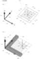
- Figure 1 shows a perspective view of an example of an embodiment of a room cursor (140) according to the present invention, preferably as displayed to a user via a visualization means, such as a computer screen, multiple computer screens, a projector, or the like.
- a visualization means such as a computer screen, multiple computer screens, a projector, or the like.
- Figures 1, 2 , and 4 to 16 may be a graphical representation or a portion of a graphical representation as displayed to a user via a visualization means.
- the CAD model comprises a coordinate system.
- the coordinate system comprises an origin (100), a height direction (101, Z), and two mutually orthogonal horizontal directions (102, Y; 103, X).
- a position cursor 150, 151, 152, 153) is displayed.
- the position cursor preferably tracks the movements obtained from a user input device, such as a computer mouse, a touchpad, a trackball, or the like.
- a planar room cursor (140) is associated with the position cursor (150).
- the planar room cursor (140) is perpendicular to the height direction (101, Z).
- the room cursor comprises an inner square (154) and a band (160, 161, 162, 163, 180, 181, 182, 183) around the inner square (154).
- the inner square comprises an edge length, e.g. 1m (numerical value 1000).
- the band comprises four edge parts (160, 161, 162, 163).
- Each edge part comprises a thickness (t), perpendicular to the height direction (101, Z), equal to the wall thickness, e.g. 25 cm (numerical value 250).
- Each edge part (160, 161, 162, 163) comprises an outer rim (170, 171, 172, 173).
- Each outer rim is parallel to one of the horizontal directions of the coordinate system.
- Each pair of non-parallel edge parts comprises a corresponding corner, e.g. non-parallel edge parts (160) and (161) comprise corresponding corner (181).
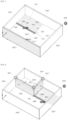
- the room cursor Upon translating the position cursor (150, 151, 152, 153) sufficiently close to the origin of the coordinate system of the CAD model, i.e. whereby outer edges (162) and (163) comprise a distance to the origin smaller than a predefined threshold, e.g. the combined distance of two times the band width (t) and the side of the inner square (140), the room cursor is shown to snap onto the coordinate system, preferably in the first quadrant of the plane perpendicular to the height direction, as is shown in Figure 2 .
- the outer rim (172) of edge part (162) is shown to snap onto direction (103, X)
- the outer rim (173) of edge part (163) is shown to snap onto direction (102, Y).
- these two non-parallel edge parts (162, 163) of the band are fixed based on said snapping, and the pivot region is positioned in the band at the corresponding corner (183) of the two fixed edge parts (162, 163).
- a confirmation of the positioned pivot region may be obtained via a user input device, e.g. by clicking a computer mouse button, a touchpad, a trackball button, or the like.
- Figure 3 shows a top view of an embodiment of a planar room cursor (140) and nine locations (300, 301, 302, 303, 304, 305, 306, 307, 308) within the room cursor, which may be associated with a pivot region depending on the context.
- the pivot region In case two non-parallel edge parts are fixed, the pivot region is positioned in a corresponding corner location (305, 306, 307, 308). In case one edge part is fixed, the pivot region is positioned at a corresponding central location (301, 302, 303, 304) within the edge part. In case zero edge parts are fixed, the pivot region is positioned centrally in the rectangle (154) of the room cursor.
- the plane of the pivot region is partitioned into nine sectors by the four lines defined by the outer edges of the square pivot region.
- the nine sectors are:
- the plane is partitioned into non-overlapping sectors, whereby each position in the plane corresponds with a sector.
- a position in a sector of the plane is obtained via a user input device, for example via a computer mouse.
- This position may be defined by a set of coordinates, such as, for example, two-dimensional coordinates within the plane, three-dimensional coordinates with respect to the coordinate system of the CAD model, or the like.
- a drawing operation associated with this sector is automatically performed. The drawing operation depends on the sector. The drawing operation may further depend on the relative location of the sector with respect to the location of the room cursor upon obtaining said pivot region. Specific embodiments of the latter case are elaborated upon below.
- the central pivot sector may be associated with a void drawing operation.
- the void drawing operation may involve a release of the pivot region, whereby a previously fixed positioned pivot region becomes unfixed, allowing free unconstrained movement of the planar room cursor.
- Each corner sector may be associated with a room or building drawing operation, comprising the insertion, removal and/or repositioning of multiple walls and/or wall portions.
- Each edge sector may be associated with a wall drawing operation involving the insertion or removal of one wall and/or wall portion.
- Removal of a wall may be achieved by movement of the cursor through a wall.
- a square pivot region may be located inside a wall via snapping of an edge part of the room cursor into the wall, and the rectangle of the room cursor comprising the snapped edge part may thereby be positioned at a first side of the wall.
- a position in a corner sector is obtained via a user input device, whereby the position is on a second side of the wall obverse to the first side. Said wall or a portion of said wall is then removed, and two or more walls and/or wall portions are inserted based on said obtained position.
- the wall into which is snapped may be retained by staying on the same side of the wall.
- a square pivot region may be located inside a wall via snapping of an edge part of the room cursor into the wall, and the rectangle of the room cursor comprising the snapped edge part may thereby be positioned at a first side of the wall.
- a position in a corner sector is obtained via a user input device, whereby the position is on the first side of the wall. Two or more walls and/or wall portions are inserted based on said obtained position, at least one of which is connected to said wall comprising the pivot region.
- Removal of a wall may be achieved by obtaining a pivot region and a position within said wall.
- a square pivot region may be located inside a wall via snapping of an edge part of the room cursor into the wall.
- a position in an edge sector is obtained via a user input device, whereby said position is inside said wall.
- a wall portion of said wall is thereupon removed, comprising a length and a location based on said pivot region and said position.
- a connection type between at least two walls is automatically adjusted upon obtaining said position which triggers said drawing operation involving at least one of said at least two walls, based on a predetermined heuristic set of rules.
- a predetermined heuristic set of rules may comprise one or more, and preferably all, of the following rules:
- the model comprises a base height and zero, one or more slabs.
- the pivot region is obtained via a horizontal translation within the model obtained via a user input device.
- Said plane is tangent to a top face of a slab in case said horizontal translation within the CAD model corresponds to a horizontal position associated with a slab, and said plane is positioned at base height otherwise.
- Said drawing operation thereby comprises leaving the slab unchanged, adjusting the slab, or removing the slab in case said plane is tangent to a top face of said slab; and inserting a slab in case said plane is positioned at the base height.
- 'inner' walls When the plane is tangent to the top face of a slab, 'inner' walls may be inserted comprising a bottom face tangent to the top face of the slab, i.e. inner walls on top of the slab. Otherwise, when the plane is at base height, 'outer' walls comprising a bottom face at base height may be inserted.
- the model may comprise a building story comprising a slab and one or more walls.
- a visualization means an addition widget in conjunction with the building story may be displayed.
- a selection of an addition action may be obtained via a user input device, preferably via said addition widget.
- a duplication of said building story may be inserted, preferably on top of said building story.
- a pair of three-dimensional walls (298) extending in the height direction (101, Z) and comprising a thickness equal to said wall thickness (t) is displayed via the visualization means to emerge on top of the fixed edge parts, to indicate a drawing operation associated with the current position of the pivot region and the position cursor.
- a drawing cursor is shown comprising a size which depends on the positioned pivot region and the position cursor.
- FIG 4 an example of a drawing cursor (440) is shown, upon confirming the location (408) of the pivot region at the origin (100) of the coordinate system.
- the position cursor (150) is located in a corner sector of the pivot region. Said corner sector is associated with the insertion of a rectangular slab, as no slab is present at the origin, and four outer sidewalls, with bottom face at zero elevation, i.e. base height.
- the drawing cursor (440) comprises an inner rectangle (454) comprising an inner first dimension (Lx) and an inner second dimension (Ly).
- the drawing cursor further comprises an outer band, comprising four edge parts (460, 461, 462, 463), whereby each edge part comprises a thickness (t) equal to said wall thickness.
- the size of the inner rectangle is entirely determined by the position cursor (150).
- two distance indicators (490, 491; 490', 491') are displayed, indicating the spatial separations of the walls to be inserted, corresponding to the dimensions of the inner rectangle (454).
- Each distance indicator comprises a line (490, 490') in between two pairs of walls and a corresponding numerical value (491, 491') of the corresponding distance.
- the user may constrain the first inner dimension (Lx) by overwriting the numerical value of the corresponding distance indicator, as has been performed at the particular instance shown in Figure 4 .
- the remaining unconstrained distance, corresponding to the inner second dimension (Ly) remains, at first, determined by the position cursor, and may, subsequently, also be constrained by the user.
- a slab (594) and four corresponding outer walls (520, 520', 520", 520′′′) are inserted into the CAD model, as shown in Figure 5 .
- the outer walls comprise a thickness equal to said wall thickness (t) and a common predefined height (H).
- the connections (521, 521', 521", 521′′′) between the perpendicularly joining walls are 45° miters.
- the position cursor and a corresponding room cursor (140) are located on a top face of the slab.
- distance indicators are displayed in between the outer rims of the edge parts of the band of the room cursor and the corresponding walls.
- Each distance indicator comprises a line (590, 590', 590", 590′′′) and a corresponding numerical value (591, 591', 591", 591′′′).
- the slab and the four outer walls form a building story.
- An addition widget (599) is displayed in conjunction with the building story.
- the position cursor has been moved proximate to walls (520) and (520'), and two non-parallel edge parts of the band of the room cursor (140) are shown to be snapped into these walls, via a snap wall visualization on top of the two snapped edge parts.
- Corresponding distance indicators (690", 691"; 690′′′, 691′′′) are shown for the outer rims of the other edge parts of the room cursor.
- the pivot region is positioned correspondingly at the corner of the room cursor at the connection of the walls (520) and (520'), which are highlighted to emphasize the snapping of the room cursor at these walls.
- a drawing cursor is shown comprising a size which depends on the positioned pivot region and the position cursor.
- FIG 7 an example of a subsequent drawing cursor (740) is shown. Note that the position cursor is located in a corner sector of the positioned pivot region. Note further that the position cursor is also located within the four walls, and is therefore positioned at the same side of walls (520) and (520') as the room cursor in Figure 6 .
- the drawing cursor comprises an inner rectangle, and an outer band of thickness (t) equal to the wall thickness around the inner rectangle. Initially, the dimensions of the inner rectangle are entirely determined by the positioned pivot region and the position cursor.
- Figure 7 furthermore shows four distance indicators (790, 791; 790', 791'; 790", 791"; 790′′′, 791′′′) from the free corner of the drawing cursor.
- the user may constrain a first distance by overwriting the numerical value of the corresponding distance indicator (790, 791), e.g. to 5m (numerical value 5000), as is being performed at the particular instance shown in Figure 7 .
- a three-dimensional snap wall (798) extending in the height direction and comprising a thickness equal to said wall thickness (t) is displayed via the visualization means to emerge on top of the edge part of the band of the drawing cursor, for which the length is being constrained.
- the remaining unconstrained distance remains, at first, determined by the position cursor, and may, subsequently, also be constrained by the user.
- inner walls (820, 820') are inserted into the CAD model on top of the top face of the slab, as shown in Figure 8 .
- the inner walls comprise a thickness (t) equal to said wall thickness and a top face at an equal height as the top faces of the already inserted outer walls.
- the inner faces are positioned on top of the slab, they comprise a height equal to the height (H) of the already inserted outer walls (520, 520', 520", 520′′′) minus the thickness of the slab.
- the connections (821, 821', 821" between the walls are adjusted automatically according to the predetermined heuristic set of rules.
- Wall (920) comprises a first reference face (1023) and a second reference face (1024), defining a first side of the wall and a second side of the wall, respectively.
- the position cursor and the corresponding room cursor are located at the first side of wall (920).
- Two non-parallel edge parts of the band of the room cursor are shown to be snapped into walls (920) and (520), respectively, as the position cursor (150) is suitably positioned.
- the pivot region is positioned in the corner corresponding to the connection of walls (920) and (520).
- a drawing cursor is shown comprising a size which depends on the positioned pivot region and the position cursor.
- FIG 11 an example of a subsequent drawing cursor is shown. Note that the position cursor is located in a corner sector of the positioned pivot region. Note further that the position cursor is also located on the second side of wall (920) obverse to the first side. A wall portion (1120) of wall (920) comprising a length (Lx”) is indicated in a distinct color, for example red color, indicating pending removal of the wall portion. Initially, the dimensions of the inner rectangle of the drawing cursor are entirely determined by the positioned pivot region and the position cursor. Figure 11 furthermore shows three distance indicators from the free corner of the drawing cursor. The user may constrain a first distance by overwriting the numerical value of the corresponding distance indicator (1191), e.g.
- the position cursor is located tangent to or inside wall (520′′′), and a distance indicator (1190', 1191') for a wall to be inserted in between walls (920) and (520′′′) therefore indicates the distance in between these walls.
- wall portion (1120) is removed from the CAD model and a new wall (1220) is inserted into the CAD model, on top of the slab, yielding the situation as displayed in Figure 12 .
- the connections (1221, 1221") between the walls are adjusted automatically according to the predetermined heuristic set of rules.
- FIG. 13 Two walls have been added with respect to Figure 12 .
- Connection (1321) is thereby adjusted so that the collinear walls with the largest total length are joined into one long wall (920) and the end faces of the other walls are adjusted to coincide with the corresponding reference faces of the joined wall (920).
- Wall (520′′′) comprises a first reference face (1323) and a second reference face (1324), defining a first side of the wall and a second side of the wall, respectively.
- an edge part of the room cursor has been shown to snap into wall (520′′′) from the first side, which corresponds with the outside of the building story, and confirmation of the positioning of the pivot region in this wall has been obtained via a user input device.
- a drawing cursor has been obtained, and the position cursor moved to the second side of the wall (520′′′), i.e. the inside of the building story, and in particular a corner sector of the pivot region, arriving at the situation displayed in Figure 13 .
- a wall portion (1320) of wall (520′′′) comprising a length Lx′′′ is indicated in a distinct color, for example in red color, indicating pending removal of the wall portion.
- wall portion (1320) is removed and three new wall portions (1420, 1420', 1420"), corresponding to the drawing cursor indications, are inserted, as displayed in Figure 14 .
- the position cursor (150) and the room cursor (140) are positioned outside of the building story, in a plane at base height.
- One edge part of the band of the room cursor is shown to be snapped into a position along direction (102, Y) corresponding to wall (520').
- An indicative extension (1497) of said wall (520') is thereby displayed.
- a distance indicator (1490, 1491) in between an outer rim of an edge part of the band of the room cursor and wall (520") is furthermore displayed, and in the particular situation displayed in Figure 14 , the corresponding distance is constrained, e.g. to 2.5m (numerical value 2000).
- a drawing cursor is displayed, allowing to draw a new building story, such as, for example, the new building story displayed in Figure 15 .
- a new slab 1594
- a duplicate (1696) of the former building story is added on top of the former building story, as shown in Figure 16 .
- the BOX and POLYSOLID commands can be used to create buildings with vertical walls. However, the commands need to be used a dozen times and with great care.
- the present example describes the command QUICKDRAW, an embodiment according to the present invention, as implemented in BricsCAD (BIM) V19, with scheduled public release after the priority date of the present document.
- the command QUICKDRAW enables users to create a simple building with only a few computer mouse clicks.
- a transparent blue 1m x 1m square (154) is attached to the mouse cursor (position cursor). This visualization is part of the room cursor (140), a central object within the QUICKDRAW command, containing geometrical information for the placement of walls and slabs (see Figure 1 ).
- the distance indicators or so-called shooter dimensions 590, 591.
- shooter dimensions have start points in the centers of the outer edges of the room cursor, and are "shot" towards the closest parallel walls, if any. These shooter dimensions are only shown when such a parallel wall is visible in the current view.
- the dimensions are dynamic and editable, which means they can be edited one by one. When typing a dimension and pressing TAB/ENTER, it is constrained and the edit box is colored red. Of course, only one dimension in each direction can be constrained, so a constrained dimension is released when the opposite one is constrained.
- the pivot When clicking a first time, a small square with side length the wall thickness, the so-called pivot, is placed based on the fixed edges (by snapping or constraining dimensions). As such, the pivot has nine possible locations w.r.t. the initial room cursor (see Figure 3 ):
- the room/building extending mode (drawing mode) is activated.
- the size of the room cursor is no longer fixed (drawing cursor), but is adapted based on the location of the fixed pivot and the mouse cursor.
- drawing mode there are also (up to) four dimensions present: the length and width (inner dimensions) of the room/building, and two shooter dimensions - resp. X- and Y-aligned - starting from the loose corner of the extending room cursor, shot at the closest parallel wall, if any. Together with the magnetic snapping, as described above, it is possible to dimension the future room/building as desired. (See Figure 4 .)
- the information in the current room cursor is used to create slabs and walls, add BIM data to them and place them in the drawing (CAD model). If the room cursor is at zero elevation, (up to) four outer walls are created and a slab is placed between these walls, resulting in a new building. This last case is depicted in Figure 5 . However, if the room cursor resides on an existent slab, only (inner) walls are placed and thus a room is created.
- the wall placement behaves intelligently, as the walls will only be placed in the first lump of the room cursor (drawing cursor). To make this more concrete, when the (extending) room cursor (drawing cursor) is cut by existent walls, only the part of room cursor in which the pivot resides, is taken into account for wall placement. This results in walls being "cut" at present walls.
- the QUICKDRAW command intelligently fixes the connection between them.
- the different use cases are listed:
- each building in the model gets a "+" widget (addition widget), attached to the top floor of the building.
- This is an application of the Widget API, using the model-view separation. Clicking this button results in copying the top floor of this building. This means all walls and slabs assigned to the relevant building and story are cloned, a new story is created and these new objects are assigned to that new story.
Landscapes
- Engineering & Computer Science (AREA)
- Physics & Mathematics (AREA)
- Geometry (AREA)
- General Physics & Mathematics (AREA)
- Theoretical Computer Science (AREA)
- Computer Hardware Design (AREA)
- Architecture (AREA)
- General Engineering & Computer Science (AREA)
- Structural Engineering (AREA)
- Computational Mathematics (AREA)
- Mathematical Analysis (AREA)
- Mathematical Optimization (AREA)
- Pure & Applied Mathematics (AREA)
- Evolutionary Computation (AREA)
- Civil Engineering (AREA)
- Computer Graphics (AREA)
- Software Systems (AREA)
- Processing Or Creating Images (AREA)
Claims (13)
- Computerimplementiertes Verfahren zur Wandzeichnung in einem computergestützten Designmodell, wobei das Modell eine Höhenrichtung (101) umfasst, wobei das Verfahren die folgenden Schritte umfasst:- Erhalten einer Wanddicke (t);- Erhalten einer ersten Position für eine quadratische Region (300, 301, 302, 303, 304, 305, 306, 307, 308), die sogenannte Schwenkregion, in einer Ebene senkrecht zu der Höhenrichtung (101), wobei die Schwenkregion (300, 301, 302, 303, 304, 305, 306, 307, 308) vier Außenkanten umfasst, wobei jede Kante eine Kantenlänge gleich der Wanddicke (t) aufweist und jede Kante eine Linie definiert, wobei die Linien die Ebene in einen zentralen Schwenksektor, vier Kantensektoren und vier Ecksektoren unterteilen, wobei:- der zentrale Schwenksektor mit der Schwenkregion (300, 301, 302, 303, 304, 305, 306, 307, 308) zusammenfällt und mit einem Leerzeichnungsvorgang assoziiert ist, der eine Freigabe der Schwenkregion (300, 301, 302, 303, 304, 305, 306, 307, 308) involviert, wodurch eine zuvor fixierte positionierte Schwenkregion unfixiert wird;- jeder Kantensektor tangential zu einer Kante der Schwenkregion (300, 301, 302, 303, 304, 305, 306, 307, 308) und in einer Richtung senkrecht zu der Kante und zu der Höhenrichtung (101) uneingeschränkt ist und mit einem Wandzeichnungsvorgang assoziiert ist, der die Einfügung oder Entfernung einer Wand und/oder eines Wandabschnittes involviert;- jeder Ecksektor tangential zu einer Ecke der Schwenkregion (300, 301, 302, 303, 304, 305, 306, 307, 308) und in zwei Richtungen der Ebene senkrecht zu der Höhenrichtung (101) uneingeschränkt ist und mit einem Raum- oder Gebäudezeichnungsvorgang assoziiert ist, der die Einfügung, Entfernung und/oder Neupositionierung von mehreren Wänden (820, 820') und/oder Wandabschnitten (1120) umfasst;- Erhalten einer zweiten Position in einem Kantensektor oder Ecksektor über eine Benutzereingabevorrichtung;- automatisches Durchführen des Zeichnungsvorgangs, der mit dem Kantensektor oder Ecksektor assoziiert ist, wobei sich j ede(r) der Wände (820, 820') und/oder Wandabschnitte (1120) in der Höhenrichtung (101) erstreckt und eine Länge senkrecht zu der Höhenrichtung basierend auf der zweiten Position umfasst.
- Computerimplementiertes Verfahren nach dem vorhergehenden Anspruch 1, wobei das Erhalten einer quadratischen Schwenkregion in einer Ebene senkrecht zu der Höhenrichtung (101) Folgendes umfasst:- Anzeigen, über ein Visualisierungsmittel, eines ebenen Raumcursors (140) senkrecht zu der Höhenrichtung (101), wobei der Raumcursor (140) ein Rechteck (154) und ein Band (160, 161, 162, 163, 180, 181, 182, 183) um das Rechteck (154) umfasst, wobei das Band vier Kantenteile (160, 161, 162, 163) umfasst, die jeweils eine Breite (t) gleich der Wanddicke umfassen;- Erhalten einer Verschiebung für den Raumcursor (140) innerhalb des Modells über eine Benutzereingabevorrichtung; und- Bestimmen einer Schwenkregion (300, 301, 302, 303, 304, 305, 306, 307, 308) basierend auf dem verschobenen Raumcursor (140).
- Computerimplementiertes Verfahren nach dem vorhergehenden Anspruch 2, wobei das Modell eine Wand (520, 520') umfasst, die zwei parallele Referenzflächen parallel zu der Höhenrichtung (101) und eine Dicke (t) zwischen den zwei Referenzflächen gleich der Wanddicke (t) umfasst, wobei die zwei Referenzflächen parallel zu einem äußeren Rand (170, 171, 172, 173) eines Kantenteils (160, 161, 162, 163) des Bands (160-163, 180-183) sind, wobei das Kantenteil (160, 161, 162, 163) über das Visualisierungsmittel angezeigt wird, um bei Überschneidung des Kantenteils (160, 161, 162, 163) mit der Wand (520, 520') in die Wand (520, 520') einzurasten.
- Computerimplementiertes Verfahren nach einem der vorhergehenden Ansprüche 2 und 3, wobei das Modell eine Wand (520) umfasst, die eine Referenzfläche parallel zu der Höhenrichtung (101) und parallel zu einem äußeren Rand (170, 171, 172, 173) eines Kantenteils (160, 161, 162, 163) des Bands (160-163, 180-183) umfasst, wobei ein Abstandsindikator (591) über das Visualisierungsmittel zwischen dem äußeren Rand (170, 171, 172, 173) des Kantenteils (160, 161, 162, 163) des Bands (160-163, 180-183) und der Referenzfläche der Wand bei räumlicher Trennung zwischen dem Raumcursor (140) und der Referenzfläche der Wand (520) angezeigt wird, und wobei das Verfahren den Schritt des Beschränkens des Abstands zwischen dem äußeren Rand (170, 171, 172, 173) des Kantenteils (160, 161, 162, 163) des Bands (160-163, 180-183) des Raumcursors (140) und der Referenzfläche der Wand (520) umfasst.
- Computerimplementiertes Verfahren nach einem der vorhergehenden Ansprüche 2 bis 4, wobei das Modell ein Koordinatensystem umfasst, das einen Ursprung (100), eine Höhenrichtung (101) und zwei zueinander orthogonale horizontale Richtungen (102, 103) umfasst, wobei jede horizontale Richtung (102, 103) parallel zu einem äußeren Rand (170, 171, 172, 173) eines Kantenteils (160, 161, 162, 163) des Bands (160-163, 180-183) des Raumcursors (140) ist, wodurch zwei äußere Ränder (172, 173) von Kantenteilen (162, 163) des Bands (160-163, 180-183) über das Visualisierungsmittel angezeigt werden, um im Falle eines Abstands zwischen jedem der verschobenen äußeren Ränder (172, 173) und dem Ursprung (100), der kleiner als ein vordefinierter Schwellenwert ist, auf den Ursprung (100) des Koordinatensystems einzurasten.
- Computerimplementiertes Verfahren nach einem der vorhergehenden Ansprüche 3 bis 5, wobei:- zwei nicht parallele Kantenteile (162, 163) des Bands (160-163, 180-183) basierend auf Einrasten oder Beschränken eines Abstands fixiert sind, wodurch die Schwenkregion (308) in dem Band (160-163, 180-183) an der entsprechenden Ecke der zwei festen Kantenteile (162, 163) positioniert ist;- ein Kantenteil (160) des Bands (160-163, 180-183) basierend auf Einrasten oder Beschränken eines Abstands fixiert ist, wodurch die Schwenkregion (301) in dem Band (160-163, 180-183) und zentral in dem fixierten Kantenteil (160) positioniert ist; oder- Nullkantenteile des Bands (160-163, 180-183) fixiert sind, wodurch die Schwenkregion (300) zentral in dem Rechteck (154) des Raumcursors (140) positioniert ist.
- Computerimplementiertes Verfahren nach den vorhergehenden Ansprüchen 3 und 6, wobei sich die quadratische Schwenkregion innerhalb der Wand (520‴; 520') befindet, wobei das Rechteck (154) des Raumcursors (140), welches das eingerastete Kantenteil umfasst, an einer ersten Seite (1323) der Wand (520‴; 520') positioniert ist, wobei das Verfahren den ersten Satz von Schritten umfasst, der die folgenden Schritte umfasst:- Erhalten der zweiten Position in einem Ecksektor über eine Benutzereingabevorrichtung, wobei die zweite Position an einer zweiten Seite (1324) der Wand (520‴) gegenüber der ersten Seite (1323) ist;- Entfernen der Wand oder eines Abschnittes (1320) der Wand (520‴); und- Einfügen von zwei oder mehr Wänden und/oder Wandabschnitten (1420, 1420', 1420") basierend auf der erhaltenen zweiten Position,oder den zweiten Satz von Schritten, der die folgenden Schritte umfasst:- Erhalten der zweiten Position in einem Ecksektor über eine Benutzereingabevorrichtung, wobei die zweite Position an der ersten Seite der Wand (520') ist; und- Einfügen von zwei oder mehr Wänden (820, 820') und/oder Wandabschnitten basierend auf der erhaltenen zweiten Position, von denen zumindest eine mit der Wand (520') verbunden ist, welche die Schwenkregion umfasst.
- Computerimplementiertes Verfahren nach einem der vorhergehenden Ansprüche 1 bis 6, wobei sich die quadratische Schwenkregion innerhalb der Wand (920) befindet, wobei das Verfahren die folgenden Schritte umfasst:- Erhalten der zweiten Position in einem Kantensektor über eine Benutzereingabevorrichtung, wobei die zweite Position innerhalb der Wand (920) ist; und- Entfernen eines Wandabschnittes (1120) der Wand (920), der eine Länge (Lx") und eine Stelle basierend auf der Schwenkregion und der zweiten Position umfasst.
- Computerimplementiertes Verfahren nach einem der vorhergehenden Ansprüche, wobei ein Verbindungstyp (821, 821', 821") zwischen zumindest zwei Wänden (820, 820', 520, 520') automatisch eingestellt wird, wenn die zweite Position erhalten wird, die den Zeichnungsvorgang, der zumindest eine (820, 820') von den zumindest zwei Wänden (820, 820', 520, 520') involviert, basierend auf einem vorbestimmten heuristischen Satz von Regeln auslöst.
- Computerimplementiertes Verfahren nach einem der vorhergehenden Ansprüche, wobei das Modell eine Basishöhe und null, eine oder mehrere Platten (594) umfasst, wobei die Schwenkregion über eine horizontale Verschiebung innerhalb des Modells über eine Benutzereingabevorrichtung erhalten wird, wobei die Ebene tangential zu einer oberen Fläche einer Platte (594) ist, falls die horizontale Verschiebung innerhalb des Modells einer horizontalen Position entspricht, die mit einer Platte assoziiert ist, und die Ebene ansonsten auf der Basishöhe positioniert ist, wobei der Zeichnungsvorgang Folgendes umfasst:- Lassen der Platte unverändert, Einstellen der Platte (1494) oder Entfernen der Platte, falls die Ebene tangential zu einer oberen Fläche der Platte ist; und- Einfügen einer Platte, falls die Ebene auf der Basishöhe positioniert ist.
- Computerimplementiertes Verfahren nach einem der vorhergehenden Ansprüche, wobei das Modell ein Gebäudegeschoss umfasst, das eine Platte und eine oder mehrere Wände umfasst, wobei das Verfahren die folgenden Schritte umfasst:- optional Anzeigen, über ein Visualisierungsmittel, eines Zusatz-Widgets (599) in Verbindung mit dem Gebäudegeschoss;- Erhalten einer Auswahl einer Zusatzhandlung über eine Benutzereingabevorrichtung, optional über das Zusatz-Widget (599); und- Einfügen einer Duplikation (1696) des Gebäudegeschosses, bevorzugt oben auf dem Gebäudegeschoss.
- Computersystem zur Wandzeichnung in einem computergestützten Designmodell, wobei das Computersystem zum Durchführen des computerimplementierten Verfahrens nach einem der vorhergehenden Ansprüche 1 bis 11 konfiguriert ist.
- Computerprogrammprodukt zur Wandzeichnung in einem computergestützten Designmodell, wobei das Computerprogrammprodukt Anweisungen umfasst, die, wenn das Computerprogrammprodukt durch einen Computer ausgeführt wird, den Computer veranlassen, das computerimplementierte Verfahren nach einem der vorhergehenden Ansprüche 1 bis 11 durchzuführen.
Priority Applications (2)
| Application Number | Priority Date | Filing Date | Title |
|---|---|---|---|
| EP18194897.7A EP3623967B1 (de) | 2018-09-17 | 2018-09-17 | Verbesserte 3d-wandzeichnung in computergestütztem design |
| US16/207,403 US11010500B2 (en) | 2018-09-17 | 2018-12-03 | Direct room modeling in computer-aided design |
Applications Claiming Priority (1)
| Application Number | Priority Date | Filing Date | Title |
|---|---|---|---|
| EP18194897.7A EP3623967B1 (de) | 2018-09-17 | 2018-09-17 | Verbesserte 3d-wandzeichnung in computergestütztem design |
Publications (2)
| Publication Number | Publication Date |
|---|---|
| EP3623967A1 EP3623967A1 (de) | 2020-03-18 |
| EP3623967B1 true EP3623967B1 (de) | 2025-05-28 |
Family
ID=63637782
Family Applications (1)
| Application Number | Title | Priority Date | Filing Date |
|---|---|---|---|
| EP18194897.7A Active EP3623967B1 (de) | 2018-09-17 | 2018-09-17 | Verbesserte 3d-wandzeichnung in computergestütztem design |
Country Status (2)
| Country | Link |
|---|---|
| US (1) | US11010500B2 (de) |
| EP (1) | EP3623967B1 (de) |
Families Citing this family (12)
| Publication number | Priority date | Publication date | Assignee | Title |
|---|---|---|---|---|
| EP3629203A1 (de) * | 2018-09-26 | 2020-04-01 | Bricsys NV | Verbesserte parallele flächenausrichtung in cad |
| EP3675062A1 (de) | 2018-12-29 | 2020-07-01 | Dassault Systèmes | Lernen eines neuronalen netzwerks zur inferenz von soliden cad-merkmalen |
| EP3675063B1 (de) * | 2018-12-29 | 2026-02-11 | Dassault Systèmes | Herstellung eines datensatzes zur inferenz von festen cad-merkmalen |
| WO2021161865A1 (ja) * | 2020-02-13 | 2021-08-19 | 三菱電機株式会社 | 寸法作成装置、寸法作成方法及びプログラム |
| CN112052503B (zh) * | 2020-09-04 | 2021-04-13 | 东南大学 | 一种基于人工智能的商业街区建筑体块生成的方法 |
| US11790122B2 (en) * | 2020-11-02 | 2023-10-17 | Etakeoff, Llc. | Predictive vector guide for construction cost estimation |
| CN112802151B (zh) * | 2020-12-25 | 2023-02-17 | 佛山欧神诺云商科技有限公司 | 一种墙线绘制方法、电子设备、存储介质 |
| CN113653367A (zh) * | 2021-01-19 | 2021-11-16 | 重庆华瑞铝业有限公司 | 一种快速搭建轻钢别墅的方法 |
| US12373612B2 (en) * | 2021-05-03 | 2025-07-29 | Wall to Wall, LLC | System, method and computer program product for efficient design of buildings |
| US12093615B2 (en) * | 2022-05-05 | 2024-09-17 | D.To, Inc. | Apparatus and methods for determining and solving design problems using machine learning |
| CN115113952B (zh) * | 2022-08-30 | 2022-11-08 | 天津理工大学 | Cim平台下海量高精度多源模型加载方法及系统 |
| CN119272380B (zh) * | 2024-09-30 | 2025-04-29 | 国泰新点软件股份有限公司 | 建筑外墙外侧定位方法、系统、设备及存储介质 |
Family Cites Families (11)
| Publication number | Priority date | Publication date | Assignee | Title |
|---|---|---|---|---|
| US7277572B2 (en) * | 2003-10-10 | 2007-10-02 | Macpearl Design Llc | Three-dimensional interior design system |
| US7629985B2 (en) * | 2006-01-26 | 2009-12-08 | Autodesk, Inc. | Method for creation of architectural space objects for area and volume calculation |
| US20080015823A1 (en) * | 2006-06-16 | 2008-01-17 | Tectonic Network, Inc. | Extensible building information model toolset |
| US8117558B2 (en) * | 2006-11-27 | 2012-02-14 | Designin Corporation | Converting web content into two-dimensional CAD drawings and three-dimensional CAD models |
| US20090138113A1 (en) * | 2006-11-27 | 2009-05-28 | Designin Corporation | Systems, methods, and computer program products for home and landscape design |
| US8253731B2 (en) * | 2006-11-27 | 2012-08-28 | Designin Corporation | Systems, methods, and computer program products for home and landscape design |
| US8260581B2 (en) * | 2006-11-27 | 2012-09-04 | Designin Corporation | Joining and disjoining individual rooms in a floor plan |
| US8954297B2 (en) * | 2012-01-02 | 2015-02-10 | Flux Factory, Inc. | Automated and intelligent structure design generation and exploration |
| US9977844B2 (en) * | 2014-05-13 | 2018-05-22 | Atheer, Inc. | Method for providing a projection to align 3D objects in 2D environment |
| US10699484B2 (en) * | 2016-06-10 | 2020-06-30 | Dirtt Environmental Solutions, Ltd. | Mixed-reality and CAD architectural design environment |
| US11004270B2 (en) * | 2018-09-11 | 2021-05-11 | Houzz, Inc. | Virtual item placement system |
-
2018
- 2018-09-17 EP EP18194897.7A patent/EP3623967B1/de active Active
- 2018-12-03 US US16/207,403 patent/US11010500B2/en active Active
Non-Patent Citations (1)
| Title |
|---|
| CGBENNER: "Customizing the Inventor Marking Menu - Cad Tips, Tricks & Workarounds", 6 February 2015 (2015-02-06), XP055821766, Retrieved from the Internet <URL:https://cadtipstricks.wordpress.com/2015/02/06/customizing-the-inventor-marking-menu/> [retrieved on 20210706] * |
Also Published As
| Publication number | Publication date |
|---|---|
| US20200089819A1 (en) | 2020-03-19 |
| EP3623967A1 (de) | 2020-03-18 |
| US11010500B2 (en) | 2021-05-18 |
Similar Documents
| Publication | Publication Date | Title |
|---|---|---|
| EP3623967B1 (de) | Verbesserte 3d-wandzeichnung in computergestütztem design | |
| CN111859511B (zh) | 建筑模型生成立面施工图的方法、装置 | |
| Dore et al. | Semi-automatic modelling of building facades with shape grammars using historic building information modelling | |
| EP2153308B1 (de) | Verfahren und vorrichtungen zum umgehen mit einem konflikt in einer cad-zeichnung | |
| US20090273598A1 (en) | Methods and apparatuses for automatically converting objects in CAD drawing from two-dimensions to three-dimensions | |
| US11010499B2 (en) | User-selected dynamic dimensions in computer-aided design | |
| US11361119B2 (en) | Method, computer program product, and server for positioning a structural element in a 2D section of a CAD structure | |
| JP7388837B2 (ja) | 機械的構造を表す3dモデル化オブジェクトの設計 | |
| JP6694192B1 (ja) | 建材見積りシステム、その管理サーバ、及び建材見積り方法 | |
| EP1729233A2 (de) | CAD-Verfahren, CAD-System und Programmspeichermedium mit gespeichertem CAD-Programm | |
| Zmugg et al. | Procedural architecture using deformation-aware split grammars | |
| JP2017146818A (ja) | 三次元データ処理装置および三次元データ処理方法 | |
| US11698998B2 (en) | Computer aided design (CAD) model connection propagation | |
| JP7456262B2 (ja) | 三次元モデル作成支援装置及びプログラム | |
| CN114239106A (zh) | 一种基于bim的楼层信息可视化方法、装置及介质 | |
| US20210073431A1 (en) | Feature replication in a cad model | |
| JP6127331B2 (ja) | 配筋検証支援装置及びそのプログラム | |
| EP3629203A1 (de) | Verbesserte parallele flächenausrichtung in cad | |
| JP7795308B2 (ja) | 3dアニメーションのレンダリング方法 | |
| CN117576309A (zh) | 建筑图纸三维化方法、设备以及可读存储介质 | |
| JP2016184331A (ja) | 3dモデル作成装置、3dモデル作成方法及び3dモデル作成プログラム | |
| KR100329817B1 (ko) | 2차원 캐드의 형상 및 위치정보 추출 시스템과 그 방법 | |
| US10394435B2 (en) | Method for manipulating a computer aided design (CAD) model by a drag operation, a computer program product and a server therefore | |
| KR102752644B1 (ko) | 레이아웃 플랜 편집 방법, 시스템 및 컴퓨터 판독 가능 저장 매체 | |
| JP4268023B2 (ja) | 擬似立体図作成システム及びその方法 |
Legal Events
| Date | Code | Title | Description |
|---|---|---|---|
| PUAI | Public reference made under article 153(3) epc to a published international application that has entered the european phase |
Free format text: ORIGINAL CODE: 0009012 |
|
| STAA | Information on the status of an ep patent application or granted ep patent |
Free format text: STATUS: THE APPLICATION HAS BEEN PUBLISHED |
|
| AK | Designated contracting states |
Kind code of ref document: A1 Designated state(s): AL AT BE BG CH CY CZ DE DK EE ES FI FR GB GR HR HU IE IS IT LI LT LU LV MC MK MT NL NO PL PT RO RS SE SI SK SM TR |
|
| AX | Request for extension of the european patent |
Extension state: BA ME |
|
| STAA | Information on the status of an ep patent application or granted ep patent |
Free format text: STATUS: REQUEST FOR EXAMINATION WAS MADE |
|
| 17P | Request for examination filed |
Effective date: 20200904 |
|
| RBV | Designated contracting states (corrected) |
Designated state(s): AL AT BE BG CH CY CZ DE DK EE ES FI FR GB GR HR HU IE IS IT LI LT LU LV MC MK MT NL NO PL PT RO RS SE SI SK SM TR |
|
| STAA | Information on the status of an ep patent application or granted ep patent |
Free format text: STATUS: EXAMINATION IS IN PROGRESS |
|
| 17Q | First examination report despatched |
Effective date: 20210712 |
|
| REG | Reference to a national code |
Ref legal event code: R079 Ipc: G06F0017000000 Ref country code: DE Ref document number: 602018082254 Country of ref document: DE Free format text: PREVIOUS MAIN CLASS: G06F0017500000 |
|
| GRAP | Despatch of communication of intention to grant a patent |
Free format text: ORIGINAL CODE: EPIDOSNIGR1 |
|
| STAA | Information on the status of an ep patent application or granted ep patent |
Free format text: STATUS: GRANT OF PATENT IS INTENDED |
|
| RIC1 | Information provided on ipc code assigned before grant |
Ipc: G06T 17/00 20060101ALI20241203BHEP Ipc: G06F 17/00 20190101AFI20241203BHEP |
|
| INTG | Intention to grant announced |
Effective date: 20250107 |
|
| GRAS | Grant fee paid |
Free format text: ORIGINAL CODE: EPIDOSNIGR3 |
|
| GRAA | (expected) grant |
Free format text: ORIGINAL CODE: 0009210 |
|
| STAA | Information on the status of an ep patent application or granted ep patent |
Free format text: STATUS: THE PATENT HAS BEEN GRANTED |
|
| AK | Designated contracting states |
Kind code of ref document: B1 Designated state(s): AL AT BE BG CH CY CZ DE DK EE ES FI FR GB GR HR HU IE IS IT LI LT LU LV MC MK MT NL NO PL PT RO RS SE SI SK SM TR |
|
| REG | Reference to a national code |
Ref country code: GB Ref legal event code: FG4D |
|
| REG | Reference to a national code |
Ref country code: CH Ref legal event code: EP |
|
| REG | Reference to a national code |
Ref country code: DE Ref legal event code: R096 Ref document number: 602018082254 Country of ref document: DE |
|
| REG | Reference to a national code |
Ref country code: IE Ref legal event code: FG4D |
|
| REG | Reference to a national code |
Ref country code: NL Ref legal event code: MP Effective date: 20250528 |
|
| PG25 | Lapsed in a contracting state [announced via postgrant information from national office to epo] |
Ref country code: FI Free format text: LAPSE BECAUSE OF FAILURE TO SUBMIT A TRANSLATION OF THE DESCRIPTION OR TO PAY THE FEE WITHIN THE PRESCRIBED TIME-LIMIT Effective date: 20250528 Ref country code: ES Free format text: LAPSE BECAUSE OF FAILURE TO SUBMIT A TRANSLATION OF THE DESCRIPTION OR TO PAY THE FEE WITHIN THE PRESCRIBED TIME-LIMIT Effective date: 20250528 |
|
| PGFP | Annual fee paid to national office [announced via postgrant information from national office to epo] |
Ref country code: DE Payment date: 20250919 Year of fee payment: 8 |
|
| REG | Reference to a national code |
Ref country code: LT Ref legal event code: MG9D |
|
| PG25 | Lapsed in a contracting state [announced via postgrant information from national office to epo] |
Ref country code: GR Free format text: LAPSE BECAUSE OF FAILURE TO SUBMIT A TRANSLATION OF THE DESCRIPTION OR TO PAY THE FEE WITHIN THE PRESCRIBED TIME-LIMIT Effective date: 20250829 Ref country code: NO Free format text: LAPSE BECAUSE OF FAILURE TO SUBMIT A TRANSLATION OF THE DESCRIPTION OR TO PAY THE FEE WITHIN THE PRESCRIBED TIME-LIMIT Effective date: 20250828 |
|
| PG25 | Lapsed in a contracting state [announced via postgrant information from national office to epo] |
Ref country code: PL Free format text: LAPSE BECAUSE OF FAILURE TO SUBMIT A TRANSLATION OF THE DESCRIPTION OR TO PAY THE FEE WITHIN THE PRESCRIBED TIME-LIMIT Effective date: 20250528 Ref country code: NL Free format text: LAPSE BECAUSE OF FAILURE TO SUBMIT A TRANSLATION OF THE DESCRIPTION OR TO PAY THE FEE WITHIN THE PRESCRIBED TIME-LIMIT Effective date: 20250528 |
|
| PG25 | Lapsed in a contracting state [announced via postgrant information from national office to epo] |
Ref country code: BG Free format text: LAPSE BECAUSE OF FAILURE TO SUBMIT A TRANSLATION OF THE DESCRIPTION OR TO PAY THE FEE WITHIN THE PRESCRIBED TIME-LIMIT Effective date: 20250528 |
|
| PGFP | Annual fee paid to national office [announced via postgrant information from national office to epo] |
Ref country code: BE Payment date: 20250717 Year of fee payment: 8 Ref country code: GB Payment date: 20250919 Year of fee payment: 8 |
|
| PG25 | Lapsed in a contracting state [announced via postgrant information from national office to epo] |
Ref country code: HR Free format text: LAPSE BECAUSE OF FAILURE TO SUBMIT A TRANSLATION OF THE DESCRIPTION OR TO PAY THE FEE WITHIN THE PRESCRIBED TIME-LIMIT Effective date: 20250528 |
|
| PGFP | Annual fee paid to national office [announced via postgrant information from national office to epo] |
Ref country code: FR Payment date: 20250922 Year of fee payment: 8 |
|
| PG25 | Lapsed in a contracting state [announced via postgrant information from national office to epo] |
Ref country code: RS Free format text: LAPSE BECAUSE OF FAILURE TO SUBMIT A TRANSLATION OF THE DESCRIPTION OR TO PAY THE FEE WITHIN THE PRESCRIBED TIME-LIMIT Effective date: 20250828 |
|
| PG25 | Lapsed in a contracting state [announced via postgrant information from national office to epo] |
Ref country code: IS Free format text: LAPSE BECAUSE OF FAILURE TO SUBMIT A TRANSLATION OF THE DESCRIPTION OR TO PAY THE FEE WITHIN THE PRESCRIBED TIME-LIMIT Effective date: 20250928 |
|
| PG25 | Lapsed in a contracting state [announced via postgrant information from national office to epo] |
Ref country code: LV Free format text: LAPSE BECAUSE OF FAILURE TO SUBMIT A TRANSLATION OF THE DESCRIPTION OR TO PAY THE FEE WITHIN THE PRESCRIBED TIME-LIMIT Effective date: 20250528 |
|
| REG | Reference to a national code |
Ref country code: AT Ref legal event code: MK05 Ref document number: 1799016 Country of ref document: AT Kind code of ref document: T Effective date: 20250528 |
|
| PG25 | Lapsed in a contracting state [announced via postgrant information from national office to epo] |
Ref country code: SM Free format text: LAPSE BECAUSE OF FAILURE TO SUBMIT A TRANSLATION OF THE DESCRIPTION OR TO PAY THE FEE WITHIN THE PRESCRIBED TIME-LIMIT Effective date: 20250528 Ref country code: AT Free format text: LAPSE BECAUSE OF FAILURE TO SUBMIT A TRANSLATION OF THE DESCRIPTION OR TO PAY THE FEE WITHIN THE PRESCRIBED TIME-LIMIT Effective date: 20250528 Ref country code: DK Free format text: LAPSE BECAUSE OF FAILURE TO SUBMIT A TRANSLATION OF THE DESCRIPTION OR TO PAY THE FEE WITHIN THE PRESCRIBED TIME-LIMIT Effective date: 20250528 |
|
| PG25 | Lapsed in a contracting state [announced via postgrant information from national office to epo] |
Ref country code: CZ Free format text: LAPSE BECAUSE OF FAILURE TO SUBMIT A TRANSLATION OF THE DESCRIPTION OR TO PAY THE FEE WITHIN THE PRESCRIBED TIME-LIMIT Effective date: 20250528 |
|
| PG25 | Lapsed in a contracting state [announced via postgrant information from national office to epo] |
Ref country code: EE Free format text: LAPSE BECAUSE OF FAILURE TO SUBMIT A TRANSLATION OF THE DESCRIPTION OR TO PAY THE FEE WITHIN THE PRESCRIBED TIME-LIMIT Effective date: 20250528 |
|
| PG25 | Lapsed in a contracting state [announced via postgrant information from national office to epo] |
Ref country code: RO Free format text: LAPSE BECAUSE OF FAILURE TO SUBMIT A TRANSLATION OF THE DESCRIPTION OR TO PAY THE FEE WITHIN THE PRESCRIBED TIME-LIMIT Effective date: 20250528 Ref country code: SK Free format text: LAPSE BECAUSE OF FAILURE TO SUBMIT A TRANSLATION OF THE DESCRIPTION OR TO PAY THE FEE WITHIN THE PRESCRIBED TIME-LIMIT Effective date: 20250528 |
|
| PG25 | Lapsed in a contracting state [announced via postgrant information from national office to epo] |
Ref country code: IT Free format text: LAPSE BECAUSE OF FAILURE TO SUBMIT A TRANSLATION OF THE DESCRIPTION OR TO PAY THE FEE WITHIN THE PRESCRIBED TIME-LIMIT Effective date: 20250528 |
|
| REG | Reference to a national code |
Ref country code: DE Ref legal event code: R097 Ref document number: 602018082254 Country of ref document: DE |
|
| PLBE | No opposition filed within time limit |
Free format text: ORIGINAL CODE: 0009261 |
|
| STAA | Information on the status of an ep patent application or granted ep patent |
Free format text: STATUS: NO OPPOSITION FILED WITHIN TIME LIMIT |
|
| REG | Reference to a national code |
Ref country code: CH Ref legal event code: L10 Free format text: ST27 STATUS EVENT CODE: U-0-0-L10-L00 (AS PROVIDED BY THE NATIONAL OFFICE) Effective date: 20260409 |