EP3623901A1 - Elastomerkonstruktion für das gehäuse von rechenvorrichtungen - Google Patents
Elastomerkonstruktion für das gehäuse von rechenvorrichtungen Download PDFInfo
- Publication number
- EP3623901A1 EP3623901A1 EP19153783.6A EP19153783A EP3623901A1 EP 3623901 A1 EP3623901 A1 EP 3623901A1 EP 19153783 A EP19153783 A EP 19153783A EP 3623901 A1 EP3623901 A1 EP 3623901A1
- Authority
- EP
- European Patent Office
- Prior art keywords
- chassis
- guide
- top cover
- base component
- biasing element
- Prior art date
- Legal status (The legal status is an assumption and is not a legal conclusion. Google has not performed a legal analysis and makes no representation as to the accuracy of the status listed.)
- Granted
Links
Images




Classifications
-
- G—PHYSICS
- G06—COMPUTING OR CALCULATING; COUNTING
- G06F—ELECTRIC DIGITAL DATA PROCESSING
- G06F1/00—Details not covered by groups G06F3/00 - G06F13/00 and G06F21/00
- G06F1/16—Constructional details or arrangements
- G06F1/18—Packaging or power distribution
- G06F1/181—Enclosures
- G06F1/182—Enclosures with special features, e.g. for use in industrial environments; grounding or shielding against radio frequency interference [RFI] or electromagnetical interference [EMI]
-
- G—PHYSICS
- G06—COMPUTING OR CALCULATING; COUNTING
- G06F—ELECTRIC DIGITAL DATA PROCESSING
- G06F1/00—Details not covered by groups G06F3/00 - G06F13/00 and G06F21/00
- G06F1/16—Constructional details or arrangements
- G06F1/18—Packaging or power distribution
- G06F1/183—Internal mounting support structures, e.g. for supporting printed circuit boards
-
- H—ELECTRICITY
- H05—ELECTRIC TECHNIQUES NOT OTHERWISE PROVIDED FOR
- H05K—PRINTED CIRCUITS; CASINGS OR CONSTRUCTIONAL DETAILS OF ELECTRIC APPARATUS; MANUFACTURE OF ASSEMBLAGES OF ELECTRICAL COMPONENTS
- H05K7/00—Constructional details common to different types of electric apparatus
- H05K7/14—Mounting supporting structure in casing or on frame or rack
- H05K7/1401—Mounting supporting structure in casing or on frame or rack comprising clamping or extracting means
-
- G—PHYSICS
- G06—COMPUTING OR CALCULATING; COUNTING
- G06F—ELECTRIC DIGITAL DATA PROCESSING
- G06F1/00—Details not covered by groups G06F3/00 - G06F13/00 and G06F21/00
- G06F1/16—Constructional details or arrangements
- G06F1/18—Packaging or power distribution
- G06F1/181—Enclosures
-
- G—PHYSICS
- G06—COMPUTING OR CALCULATING; COUNTING
- G06F—ELECTRIC DIGITAL DATA PROCESSING
- G06F1/00—Details not covered by groups G06F3/00 - G06F13/00 and G06F21/00
- G06F1/16—Constructional details or arrangements
- G06F1/18—Packaging or power distribution
- G06F1/183—Internal mounting support structures, e.g. for supporting printed circuit boards
- G06F1/185—Mounting of expansion boards
-
- H—ELECTRICITY
- H05—ELECTRIC TECHNIQUES NOT OTHERWISE PROVIDED FOR
- H05K—PRINTED CIRCUITS; CASINGS OR CONSTRUCTIONAL DETAILS OF ELECTRIC APPARATUS; MANUFACTURE OF ASSEMBLAGES OF ELECTRICAL COMPONENTS
- H05K5/00—Casings, cabinets or drawers for electric apparatus
- H05K5/02—Details
- H05K5/0217—Mechanical details of casings
- H05K5/0221—Locks; Latches
-
- H—ELECTRICITY
- H05—ELECTRIC TECHNIQUES NOT OTHERWISE PROVIDED FOR
- H05K—PRINTED CIRCUITS; CASINGS OR CONSTRUCTIONAL DETAILS OF ELECTRIC APPARATUS; MANUFACTURE OF ASSEMBLAGES OF ELECTRICAL COMPONENTS
- H05K5/00—Casings, cabinets or drawers for electric apparatus
- H05K5/02—Details
- H05K5/03—Covers
-
- H—ELECTRICITY
- H05—ELECTRIC TECHNIQUES NOT OTHERWISE PROVIDED FOR
- H05K—PRINTED CIRCUITS; CASINGS OR CONSTRUCTIONAL DETAILS OF ELECTRIC APPARATUS; MANUFACTURE OF ASSEMBLAGES OF ELECTRICAL COMPONENTS
- H05K7/00—Constructional details common to different types of electric apparatus
- H05K7/14—Mounting supporting structure in casing or on frame or rack
- H05K7/1485—Servers; Data center rooms, e.g. 19-inch computer racks
- H05K7/1487—Blade assemblies, e.g. blade cases or inner arrangements within a blade
-
- H—ELECTRICITY
- H05—ELECTRIC TECHNIQUES NOT OTHERWISE PROVIDED FOR
- H05K—PRINTED CIRCUITS; CASINGS OR CONSTRUCTIONAL DETAILS OF ELECTRIC APPARATUS; MANUFACTURE OF ASSEMBLAGES OF ELECTRICAL COMPONENTS
- H05K7/00—Constructional details common to different types of electric apparatus
- H05K7/14—Mounting supporting structure in casing or on frame or rack
- H05K7/1485—Servers; Data center rooms, e.g. 19-inch computer racks
- H05K7/1488—Cabinets therefor, e.g. chassis or racks or mechanical interfaces between blades and support structures
- H05K7/1489—Cabinets therefor, e.g. chassis or racks or mechanical interfaces between blades and support structures characterized by the mounting of blades therein, e.g. brackets, rails, trays
Definitions
- the present invention relates to elastomer placement in a computing device chassis.
- Computing devices such as servers
- These chassis can be constructed in an automated assembly fashion, which provides a cheap and efficient method of manufacturing computing devices.
- automated assembly methods typically result in gaps between the components of the chassis, such as between a base component and a top cover when combined. These gaps can affect the appearance of the computing device; can cause thermal cooling or heating issues within the computing device; and can also contribute to electromagnetic interference (EMI) within the computing device.
- EMI electromagnetic interference
- These gaps cannot be made any smaller by increasing either the size of the top cover or the size of the base component due to structural concerns. If the two base component and the top cover are designed such that they physically interfere, or overlap, with each other, there can be internal stress and friction between the two components. This stress and friction can cause physical damage to either the base component or the top cover.
- the various examples of the present disclosure are directed towards a chassis for a computing device that comprises a base component, a top cover, and a biasing element.
- the base component can include a plurality of guide slots.
- the top cover can comprise a plurality of guide pins that correspond to the plurality of guide slots.
- the guide pins can be positioned in the guide slots when the base component is in a mating position with the top cover.
- the biasing element can be positioned adjacent to at least one of the guide slots. The biasing element can push against at least one of the guide pins that correspond to at least one of the guide slots in the mating position.
- the biasing element can comprise an elastomer.
- At least one of the plurality of guide slots can be tapered between an opening portion and an end portion.
- the guide slot can thus reach a smaller diameter than a diameter of a guide pin in order to yield a hard stop.
- This hard stop can position the top cover so as to define a gap between the base component and the top cover.
- the elastomer positions the top cover to define an interference fit with the base component.
- chassis and top cover can further comprise a spring to assist the biasing element to push against at least some of the guide pins.
- the spring can be incorporated into the biasing element.
- the biasing element can possess an elastic force greater than the frictional force of the top cover with the base component.
- an upper and a lower wall of the guide slot can define a functional area in which the guide pin is positioned. This positioning can assure a gap of a target size between the top cover and the base component.
- the target size can have a largest acceptable size in order to yield a target largest gap and a smallest acceptable size to yield a target smallest gap.
- the biasing element can be positioned to maintain the guide pin in the functional area.
- the functional area can be larger than a distance of the target gap such that a placement of the biasing element always provides an elastic force on the guide pin.
- the target gap can comprise a nominal distance plus or minus a predetermined deviation.
- guide slots can be provided on opposing sides of the chassis.
- a plurality of elastomers can be adjacent to each of the plurality of guide slots.
- the present disclosure is directed to computing device chassis design that includes an elastomer designed to reduce a gap between a chassis base component and a top cover.
- the elastomer can be positioned adjacent to guide slots of the chassis base component. When the guide slots receive guide pins from the top cover, the elastomer can push against the guide pins to force a close fit of the top cover against the chassis base component. Therefore, the present disclosure provides a mechanical solution to eliminate the gap between a chassis base component and a top cover. Elimination of this gap helps to standardize airflow through the computer chassis; creates a better visual appearance; and reduces the entry points of dust and debris into the computer chassis.
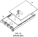
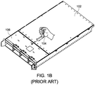
- FIGs. 1A-1D show an exemplary computer chassis and top cover, as known in the prior art.
- a conventional design includes a top cover 102, a latch module 104, and a chassis base component 106.
- FIG. 1A shows how the top cover 102 must manually be placed into the chassis base component 106 while the latch module 104 is held open. Once the top cover 102 is placed on the chassis base component 106 ( FIG. 1B ), the latch module 104 can be released ( FIG. 1C ) to secure the top cover 102 in place.
- the connection between the top cover 102 and the chassis base component 106 can be referred to as a mating position.
- FIG. 1D shows a gap between the top cover 102 and the chassis base component 106 that results from this conventional design.
- the gap is undesirable in a computer chassis design because it can allow airflow, dust, and debris to enter the computer chassis. Airflow can cause heating and cooling problems for any components of the chassis, and the dust and debris can damage computer components. Additionally, the gap can be visually unappealing.
- FIG. 2 shows an exemplary computer chassis 200 according to an embodiment of the present disclosure.
- an exemplary computer chassis can include the chassis base component 202 and guide slots 204.
- the guide slots can have an upper wall 203, a lower wall 205, an opening portion 206, and an end portion 208.
- the guide slots 204 can be located along the exterior of opposing sides of the chassis base component 202, in order to provide a plurality of locations for a top cover (not shown) to be linked to the chassis base component 202. Although eight guide slots 204 are shown in FIG. 2 , there can be any number of guide slots 204.
- the guide slot 204 can have an upper wall 203 and a lower wall 205 through which a guide pin 210 can slide.
- the guide slot 204 can have an opening portion 206, where a guide pin 210 enters, and an end portion 208, which receives the guide pin 210.
- the end portion 208 can have a width that can be approximately the same as a diameter of a guide pin 210.
- the guide slot 204 can be tapered between the opening portion 206 and the end portion 208 such that the guide slot 204 eventually reaches a smaller diameter than the diameter of a guide pin 210. This point can be referred to as a hard stop because the guide pin 210 can go no further into the guide slot 204.
- An exemplary guide pin can be cylindrically shaped, as shown in FIG. 2 .
- an exemplary guide pin can have other features, such as a groove, ridge, or hook, however no other features are needed for the guide pin to fit within the guide slot 204.
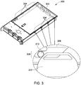
- FIG. 3 shows an exemplary elastomer placement in a computer chassis according to an embodiment of the present disclosure.
- FIG. 3 includes many of the same components as FIG. 2 , including a chassis base component 302, guide slots 304, a guide slot opening portion 306, a guide slot end portion 308.
- FIG. 3 includes a guide pin 310 and an elastomer 312.
- the guide pin 310 can be attached to a top cover (not shown), and can be pushed into the guide slot 304 when the top cover is put into a mating position with the chassis 300.
- the elastomer 312 can be placed adjacent to a guide slot 304.
- the elastomers 312 can be placed adjacent all guide slots 304, or placed adjacent to only selected guide slots 304.
- the elastomer 312 can be depressed due to the entry of the guide pin 310 so that the guide pin can be stably received in the end portion 308 of the guide slot 304. This is shown further in FIGs. 5A-5C
- the elastomer force can be varied according to the number of elastomers in the chassis base component. For example, if the chassis base component has eight guide slots and each guide slot has an elastomer, then the total elastic force exerted on the top cover will be the sum of the elastic force exerted by all eight elastomers 312. While the top cover is sliding into the guide slot 304, there can additionally be a frictional force acting on the top cover which resists the entrance of the top cover into a mating position with the chassis 300. However, the eight elastomers can have a total elastic force which is greater than the frictional force. Thereby, the elastomers can encourage and sustain a mating position between the top cover and chassis 300.
- FIG. 4A shows exemplary dimensions of a gap between a top cover 414 and a chassis base component 402, according to an embodiment of the present disclosure.
- the gap can be a nominal distance N with a standard deviation in the length of the gap D.
- FIG. 4B shows how an exemplary elastomer can be designed according to the dimensions of a target gap shown in FIG. 4A.
- FIG. 4B shows a guide slot 404, a guide slot opening portion 406, a guide slot end portion 408, a guide pin 410, and an elastomer 412. These components are similar to those discussed earlier with respect to FIGs. 2 and 3 .
- FIG. 4B shows how the elastomer 412 can be positioned to secure the guide pin 410 in a functional area.
- the functional area can be larger than the length of the nominal distance N added to the length of the standard deviation D. In some cases, the functional area can also be N minus D.
- the elastomer 412 can be configured to exert a force on the guide pin 410 whenever the guide pin 410 is in the functional area.
- the elastomer 412 can be positioned based on a desired nominal distance N and standard deviation D.
- the gap of FIG. 4A can be minimized or eliminated.
- the elastomer 412 can be located to guarantee a target gap size. When more pressure is exerted on the guide pin 410 by the elastomer 412, the top cover pushes forwards against the chassis base component. This movement reduces a size of the gap.
- FIGs. 5A-5C show an exemplary guide pin engaging with a guide slot and an elastomer, according to an embodiment of the present disclosure.
- FIGs. 5A-5C include a guide slot opening portion 506, a guide slot end portion 508, a guide pin 510, and an elastomer 512.
- FIGs. 5A-5C show that as the guide pin is pushed into the guide slot, it slides over the top of the elastomer 512 and then comes to a rest within the guide slot end portion 508.
- FIG. 5B shows that there can be a slight deformation in the elastomer 512 as the guide pin 510 comes into contact with the elastomer 512.
- a hard stop line can be provided where the guide pin 510 can slide no further along the tapered portion, or the downward sloping portion, of the guide slot end portion 508.
- This hard stop line can be where a diameter of the guide pin is substantially the same as a width of the guide slot end portion 508. This hard stop line controls a mating position of a top cover relative to the chassis.
- the position of the elastomer as shown in FIGs. 5A-5C can define an interference fit between the chassis base component and the top cover so that the top cover overlaps with the chassis base component.
- any stress incurred due to the physical configuration of the chassis base component and the top cover can be absorbed by the elastomer such that the chassis base component and the top cover will not be damaged by the interference. Therefore, the present disclosure provides advantages over conventional designs which do not provide means to absorb stress incurred by a fit between the chassis base component and the top cover.
- FIG. 6A shows an exemplary simplified elastomer design, according to an embodiment of the present disclosure.
- the elastomer design can include a guide slot 604, a guide slot end portion 608, guide pin 610, and a biasing element 614.
- the biasing element can function to push against a guide pin 610 and can position the guide pin 610 to retain its configuration at the end portion 608 of the guide slot 604.
- FIG. 6B shows an exemplary elastomer with a spring, according to an embodiment of the present disclosure.
- This embodiment of the present disclosure can include a guide pin 610, an elastomer 612, and a spring 616.
- FIG. 6B shows the spring 616 inside the elastomer 612, the spring 616 can be in any configuration so long as it exerts pressure on the guide pin 610.
- the spring 616 can server to increase an elastic force of the elastomer 612 as the elastomer 612 pushes the top cover into the chassis base component. Additionally, the spring 616 can provide additional support to the elastomer 612 in case the top cover is too heavy to be guided the guide pin 610 into the guide slot 604 by just the elastomer 612.
Landscapes
- Engineering & Computer Science (AREA)
- Theoretical Computer Science (AREA)
- Computer Hardware Design (AREA)
- General Engineering & Computer Science (AREA)
- Microelectronics & Electronic Packaging (AREA)
- Physics & Mathematics (AREA)
- Power Engineering (AREA)
- Human Computer Interaction (AREA)
- General Physics & Mathematics (AREA)
- Electromagnetism (AREA)
- Casings For Electric Apparatus (AREA)
Applications Claiming Priority (1)
| Application Number | Priority Date | Filing Date | Title |
|---|---|---|---|
| US16/133,264 US10869403B2 (en) | 2018-09-17 | 2018-09-17 | Elastomer design for computing device chassis |
Publications (2)
| Publication Number | Publication Date |
|---|---|
| EP3623901A1 true EP3623901A1 (de) | 2020-03-18 |
| EP3623901B1 EP3623901B1 (de) | 2021-06-16 |
Family
ID=65236900
Family Applications (1)
| Application Number | Title | Priority Date | Filing Date |
|---|---|---|---|
| EP19153783.6A Active EP3623901B1 (de) | 2018-09-17 | 2019-01-25 | Elastomerkonstruktion für das gehäuse von rechenvorrichtungen |
Country Status (5)
| Country | Link |
|---|---|
| US (1) | US10869403B2 (de) |
| EP (1) | EP3623901B1 (de) |
| JP (1) | JP6792007B2 (de) |
| CN (1) | CN110908463B (de) |
| TW (1) | TWI682702B (de) |
Cited By (3)
| Publication number | Priority date | Publication date | Assignee | Title |
|---|---|---|---|---|
| US11449110B2 (en) * | 2020-01-17 | 2022-09-20 | Hong Fu Jin Precision Industry (Wuhan) Co., Ltd. | Computer enclosure |
| US11459792B2 (en) * | 2019-04-24 | 2022-10-04 | Hewlett Packard Enterprise Development Lp | Rotated hood latch |
| TWI884809B (zh) * | 2024-06-13 | 2025-05-21 | 英業達股份有限公司 | 固定模組 |
Families Citing this family (1)
| Publication number | Priority date | Publication date | Assignee | Title |
|---|---|---|---|---|
| US11297730B1 (en) * | 2020-11-02 | 2022-04-05 | Quanta Computer Inc. | Tool free removable chassis cover |
Citations (3)
| Publication number | Priority date | Publication date | Assignee | Title |
|---|---|---|---|---|
| US20030227740A1 (en) * | 2002-06-05 | 2003-12-11 | Jen-Hsiang Lee | Top cover of a computer system housing |
| US20160313703A1 (en) * | 2015-04-24 | 2016-10-27 | Apple Inc. | Cover member for an input mechanism of an electronic device |
| US9696769B1 (en) * | 2015-12-31 | 2017-07-04 | Lenovo Enterprise Solutions (Singapore) Pte. Ltd. | Compute chassis having a lid that secures and removes air baffles |
Family Cites Families (27)
| Publication number | Priority date | Publication date | Assignee | Title |
|---|---|---|---|---|
| CN1142709C (zh) | 1996-11-08 | 2004-03-17 | 连接器系统工艺公司 | 电子卡 |
| US6711859B2 (en) * | 2001-06-01 | 2004-03-30 | Michael Ray Bell | System and method for fixing a first component with a second component |
| EP1466510B1 (de) | 2001-08-10 | 2017-09-27 | Oracle America, Inc. | Server blade |
| US7382623B2 (en) * | 2003-06-11 | 2008-06-03 | Dell Products L.P. | Method and system for coupling a chassis to a rail |
| US6929338B2 (en) * | 2003-09-08 | 2005-08-16 | Inventec Corp. | Computer case |
| US7995355B2 (en) | 2005-01-10 | 2011-08-09 | Stealthdrive, Inc. | Three-dimensional configurations providing electromagnetic interference shielding for electronics enclosures |
| US7481504B2 (en) * | 2005-11-23 | 2009-01-27 | King Slide Works Co., Ltd. | Mount latch structure for a telescoping slide |
| CN201032524Y (zh) * | 2006-11-30 | 2008-03-05 | 德演精密工业有限公司 | 工业计算机机箱的配置结构 |
| US7967399B1 (en) * | 2007-09-21 | 2011-06-28 | Central Industrial Supply Company | Linearly actuated chassis lock for a drawer slide |
| CN201174836Y (zh) | 2008-03-31 | 2008-12-31 | 纬创资通股份有限公司 | 电子装置拆卸的开关结构 |
| CN101965113A (zh) * | 2009-07-24 | 2011-02-02 | 鸿富锦精密工业(深圳)有限公司 | 滑轨固定装置 |
| IT1401386B1 (it) | 2010-07-30 | 2013-07-18 | Eurotech S P A | Dispositivo di raffreddamento a liquido per schede elettroniche, in particolare per unita' di elaborazione ad elevate prestazioni |
| MX2013003563A (es) * | 2010-09-30 | 2013-06-28 | Apple Inc | Dispositivo de computacion portatil. |
| US8864183B1 (en) * | 2011-07-27 | 2014-10-21 | Cisco Technology, Inc. | Mechanism to latch a cover closed |
| TWI511636B (zh) * | 2012-03-16 | 2015-12-01 | Wistron Corp | 電子裝置的機殼 |
| CN103517597B (zh) * | 2012-06-27 | 2016-05-04 | 纬创资通股份有限公司 | 电子装置、开关机构及机壳的开盖方法 |
| TWI489930B (zh) | 2012-08-28 | 2015-06-21 | 緯創資通股份有限公司 | 限位機構及其相關電子裝置 |
| TWM470490U (zh) * | 2013-09-03 | 2014-01-11 | Wistron Corp | 可滑動旋轉之門蓋機構及相關電子裝置 |
| WO2016007177A1 (en) * | 2014-07-11 | 2016-01-14 | Apple Inc. | Retention system for dynamic loading |
| TWI562710B (en) * | 2014-11-04 | 2016-12-11 | Quanta Comp Inc | Server device having one rack unit in height |
| CN106155849A (zh) * | 2015-04-17 | 2016-11-23 | 鸿富锦精密工业(武汉)有限公司 | 侦测系统及其侦测装置 |
| US10448525B2 (en) | 2015-09-28 | 2019-10-15 | Eaton Intelligent Power Limited | Moisture control systems for electrical enclosures |
| WO2017123191A1 (en) * | 2016-01-11 | 2017-07-20 | Hewlett Packard Enterprise Development Lp | Installation of modular units in a computing device |
| TWI625090B (zh) | 2016-05-30 | 2018-05-21 | 仁寶電腦工業股份有限公司 | 機箱結構 |
| CN206515752U (zh) * | 2016-08-04 | 2017-09-22 | 李玉海 | 一种散热抗冲击计算机双层机箱 |
| CN206058085U (zh) * | 2016-08-04 | 2017-03-29 | 何彩堂 | 一种计算机机箱 |
| WO2018136026A1 (en) * | 2017-01-17 | 2018-07-26 | Hewlett-Packard Development Company, L.P. | Mechanical interlock |
-
2018
- 2018-09-17 US US16/133,264 patent/US10869403B2/en active Active
- 2018-11-30 TW TW107143130A patent/TWI682702B/zh active
- 2018-12-17 CN CN201811541079.3A patent/CN110908463B/zh active Active
-
2019
- 2019-01-25 EP EP19153783.6A patent/EP3623901B1/de active Active
- 2019-02-04 JP JP2019018004A patent/JP6792007B2/ja active Active
Patent Citations (3)
| Publication number | Priority date | Publication date | Assignee | Title |
|---|---|---|---|---|
| US20030227740A1 (en) * | 2002-06-05 | 2003-12-11 | Jen-Hsiang Lee | Top cover of a computer system housing |
| US20160313703A1 (en) * | 2015-04-24 | 2016-10-27 | Apple Inc. | Cover member for an input mechanism of an electronic device |
| US9696769B1 (en) * | 2015-12-31 | 2017-07-04 | Lenovo Enterprise Solutions (Singapore) Pte. Ltd. | Compute chassis having a lid that secures and removes air baffles |
Cited By (3)
| Publication number | Priority date | Publication date | Assignee | Title |
|---|---|---|---|---|
| US11459792B2 (en) * | 2019-04-24 | 2022-10-04 | Hewlett Packard Enterprise Development Lp | Rotated hood latch |
| US11449110B2 (en) * | 2020-01-17 | 2022-09-20 | Hong Fu Jin Precision Industry (Wuhan) Co., Ltd. | Computer enclosure |
| TWI884809B (zh) * | 2024-06-13 | 2025-05-21 | 英業達股份有限公司 | 固定模組 |
Also Published As
| Publication number | Publication date |
|---|---|
| US10869403B2 (en) | 2020-12-15 |
| TWI682702B (zh) | 2020-01-11 |
| CN110908463B (zh) | 2021-09-28 |
| CN110908463A (zh) | 2020-03-24 |
| US20200093020A1 (en) | 2020-03-19 |
| EP3623901B1 (de) | 2021-06-16 |
| TW202014078A (zh) | 2020-04-01 |
| JP2020047243A (ja) | 2020-03-26 |
| JP6792007B2 (ja) | 2020-11-25 |
Similar Documents
| Publication | Publication Date | Title |
|---|---|---|
| EP3623901A1 (de) | Elastomerkonstruktion für das gehäuse von rechenvorrichtungen | |
| US7679896B2 (en) | Fixing apparatus for data storage device | |
| KR101494941B1 (ko) | 전자 장치 및 관련된 분해 해제 도구 | |
| US20120281373A1 (en) | Adjustable Riser Cage for Varying Length Adapters | |
| JP6250243B1 (ja) | 電子機器用端子保護構造及び電子機器 | |
| US20080303398A1 (en) | Slider assembly | |
| CN207851713U (zh) | 固持结构及安装结构 | |
| EP2899813A1 (de) | Steckverbinder | |
| US20110286196A1 (en) | Fixing member for fixing blindfold plate and method of fixing blindfold plate | |
| US20120275849A1 (en) | Fixing device for expansion card | |
| US20120033378A1 (en) | Electronic device module with movable shield for anti-electromagnetic interference | |
| EP3171679A1 (de) | Drahtsicherungsabdeckung für leiterplatten in einer elektronischen vorrichtung | |
| US20050195563A1 (en) | Mounting device for hard disk drives | |
| CN103140090A (zh) | 夹持结构及具有夹持结构的可携式电子装置 | |
| US20100321884A1 (en) | Mounting apparatus for pci device | |
| US9148976B2 (en) | Rail mounting mechanism | |
| US8936327B2 (en) | Bezel assembly for electronic device | |
| US20140175811A1 (en) | Latch assembly with automatic returning bolt | |
| US7315457B1 (en) | Motherboard fixing device | |
| US7542278B2 (en) | Electronic apparatus incorporating fixing mechanism | |
| US9329641B2 (en) | Securing structure and an electronic device incorporating the same | |
| US11953955B2 (en) | Fixing mechanism, interface card assembly and electronic apparatus | |
| US7667985B1 (en) | Computer network device and method of assembly | |
| US20130163172A1 (en) | Mounting apparatus for data storage device | |
| DE102015122286B3 (de) | Gehäuse für ein Computersystem sowie Computersystem |
Legal Events
| Date | Code | Title | Description |
|---|---|---|---|
| PUAI | Public reference made under article 153(3) epc to a published international application that has entered the european phase |
Free format text: ORIGINAL CODE: 0009012 |
|
| STAA | Information on the status of an ep patent application or granted ep patent |
Free format text: STATUS: THE APPLICATION HAS BEEN PUBLISHED |
|
| AK | Designated contracting states |
Kind code of ref document: A1 Designated state(s): AL AT BE BG CH CY CZ DE DK EE ES FI FR GB GR HR HU IE IS IT LI LT LU LV MC MK MT NL NO PL PT RO RS SE SI SK SM TR |
|
| AX | Request for extension of the european patent |
Extension state: BA ME |
|
| STAA | Information on the status of an ep patent application or granted ep patent |
Free format text: STATUS: REQUEST FOR EXAMINATION WAS MADE |
|
| 17P | Request for examination filed |
Effective date: 20200524 |
|
| RBV | Designated contracting states (corrected) |
Designated state(s): AL AT BE BG CH CY CZ DE DK EE ES FI FR GB GR HR HU IE IS IT LI LT LU LV MC MK MT NL NO PL PT RO RS SE SI SK SM TR |
|
| GRAP | Despatch of communication of intention to grant a patent |
Free format text: ORIGINAL CODE: EPIDOSNIGR1 |
|
| STAA | Information on the status of an ep patent application or granted ep patent |
Free format text: STATUS: GRANT OF PATENT IS INTENDED |
|
| INTG | Intention to grant announced |
Effective date: 20210112 |
|
| GRAS | Grant fee paid |
Free format text: ORIGINAL CODE: EPIDOSNIGR3 |
|
| GRAA | (expected) grant |
Free format text: ORIGINAL CODE: 0009210 |
|
| STAA | Information on the status of an ep patent application or granted ep patent |
Free format text: STATUS: THE PATENT HAS BEEN GRANTED |
|
| AK | Designated contracting states |
Kind code of ref document: B1 Designated state(s): AL AT BE BG CH CY CZ DE DK EE ES FI FR GB GR HR HU IE IS IT LI LT LU LV MC MK MT NL NO PL PT RO RS SE SI SK SM TR |
|
| REG | Reference to a national code |
Ref country code: GB Ref legal event code: FG4D |
|
| REG | Reference to a national code |
Ref country code: CH Ref legal event code: EP |
|
| REG | Reference to a national code |
Ref country code: DE Ref legal event code: R096 Ref document number: 602019005301 Country of ref document: DE |
|
| REG | Reference to a national code |
Ref country code: AT Ref legal event code: REF Ref document number: 1402875 Country of ref document: AT Kind code of ref document: T Effective date: 20210715 |
|
| REG | Reference to a national code |
Ref country code: IE Ref legal event code: FG4D |
|
| REG | Reference to a national code |
Ref country code: LT Ref legal event code: MG9D |
|
| PG25 | Lapsed in a contracting state [announced via postgrant information from national office to epo] |
Ref country code: BG Free format text: LAPSE BECAUSE OF FAILURE TO SUBMIT A TRANSLATION OF THE DESCRIPTION OR TO PAY THE FEE WITHIN THE PRESCRIBED TIME-LIMIT Effective date: 20210916 Ref country code: FI Free format text: LAPSE BECAUSE OF FAILURE TO SUBMIT A TRANSLATION OF THE DESCRIPTION OR TO PAY THE FEE WITHIN THE PRESCRIBED TIME-LIMIT Effective date: 20210616 Ref country code: LT Free format text: LAPSE BECAUSE OF FAILURE TO SUBMIT A TRANSLATION OF THE DESCRIPTION OR TO PAY THE FEE WITHIN THE PRESCRIBED TIME-LIMIT Effective date: 20210616 Ref country code: HR Free format text: LAPSE BECAUSE OF FAILURE TO SUBMIT A TRANSLATION OF THE DESCRIPTION OR TO PAY THE FEE WITHIN THE PRESCRIBED TIME-LIMIT Effective date: 20210616 |
|
| REG | Reference to a national code |
Ref country code: AT Ref legal event code: MK05 Ref document number: 1402875 Country of ref document: AT Kind code of ref document: T Effective date: 20210616 |
|
| REG | Reference to a national code |
Ref country code: NL Ref legal event code: MP Effective date: 20210616 |
|
| PG25 | Lapsed in a contracting state [announced via postgrant information from national office to epo] |
Ref country code: LV Free format text: LAPSE BECAUSE OF FAILURE TO SUBMIT A TRANSLATION OF THE DESCRIPTION OR TO PAY THE FEE WITHIN THE PRESCRIBED TIME-LIMIT Effective date: 20210616 Ref country code: NO Free format text: LAPSE BECAUSE OF FAILURE TO SUBMIT A TRANSLATION OF THE DESCRIPTION OR TO PAY THE FEE WITHIN THE PRESCRIBED TIME-LIMIT Effective date: 20210916 Ref country code: SE Free format text: LAPSE BECAUSE OF FAILURE TO SUBMIT A TRANSLATION OF THE DESCRIPTION OR TO PAY THE FEE WITHIN THE PRESCRIBED TIME-LIMIT Effective date: 20210616 Ref country code: RS Free format text: LAPSE BECAUSE OF FAILURE TO SUBMIT A TRANSLATION OF THE DESCRIPTION OR TO PAY THE FEE WITHIN THE PRESCRIBED TIME-LIMIT Effective date: 20210616 Ref country code: GR Free format text: LAPSE BECAUSE OF FAILURE TO SUBMIT A TRANSLATION OF THE DESCRIPTION OR TO PAY THE FEE WITHIN THE PRESCRIBED TIME-LIMIT Effective date: 20210917 |
|
| PG25 | Lapsed in a contracting state [announced via postgrant information from national office to epo] |
Ref country code: AT Free format text: LAPSE BECAUSE OF FAILURE TO SUBMIT A TRANSLATION OF THE DESCRIPTION OR TO PAY THE FEE WITHIN THE PRESCRIBED TIME-LIMIT Effective date: 20210616 Ref country code: CZ Free format text: LAPSE BECAUSE OF FAILURE TO SUBMIT A TRANSLATION OF THE DESCRIPTION OR TO PAY THE FEE WITHIN THE PRESCRIBED TIME-LIMIT Effective date: 20210616 Ref country code: RO Free format text: LAPSE BECAUSE OF FAILURE TO SUBMIT A TRANSLATION OF THE DESCRIPTION OR TO PAY THE FEE WITHIN THE PRESCRIBED TIME-LIMIT Effective date: 20210616 Ref country code: NL Free format text: LAPSE BECAUSE OF FAILURE TO SUBMIT A TRANSLATION OF THE DESCRIPTION OR TO PAY THE FEE WITHIN THE PRESCRIBED TIME-LIMIT Effective date: 20210616 Ref country code: PT Free format text: LAPSE BECAUSE OF FAILURE TO SUBMIT A TRANSLATION OF THE DESCRIPTION OR TO PAY THE FEE WITHIN THE PRESCRIBED TIME-LIMIT Effective date: 20211018 Ref country code: SM Free format text: LAPSE BECAUSE OF FAILURE TO SUBMIT A TRANSLATION OF THE DESCRIPTION OR TO PAY THE FEE WITHIN THE PRESCRIBED TIME-LIMIT Effective date: 20210616 Ref country code: SK Free format text: LAPSE BECAUSE OF FAILURE TO SUBMIT A TRANSLATION OF THE DESCRIPTION OR TO PAY THE FEE WITHIN THE PRESCRIBED TIME-LIMIT Effective date: 20210616 Ref country code: EE Free format text: LAPSE BECAUSE OF FAILURE TO SUBMIT A TRANSLATION OF THE DESCRIPTION OR TO PAY THE FEE WITHIN THE PRESCRIBED TIME-LIMIT Effective date: 20210616 Ref country code: ES Free format text: LAPSE BECAUSE OF FAILURE TO SUBMIT A TRANSLATION OF THE DESCRIPTION OR TO PAY THE FEE WITHIN THE PRESCRIBED TIME-LIMIT Effective date: 20210616 |
|
| PG25 | Lapsed in a contracting state [announced via postgrant information from national office to epo] |
Ref country code: PL Free format text: LAPSE BECAUSE OF FAILURE TO SUBMIT A TRANSLATION OF THE DESCRIPTION OR TO PAY THE FEE WITHIN THE PRESCRIBED TIME-LIMIT Effective date: 20210616 |
|
| REG | Reference to a national code |
Ref country code: DE Ref legal event code: R097 Ref document number: 602019005301 Country of ref document: DE |
|
| PLBE | No opposition filed within time limit |
Free format text: ORIGINAL CODE: 0009261 |
|
| STAA | Information on the status of an ep patent application or granted ep patent |
Free format text: STATUS: NO OPPOSITION FILED WITHIN TIME LIMIT |
|
| PG25 | Lapsed in a contracting state [announced via postgrant information from national office to epo] |
Ref country code: DK Free format text: LAPSE BECAUSE OF FAILURE TO SUBMIT A TRANSLATION OF THE DESCRIPTION OR TO PAY THE FEE WITHIN THE PRESCRIBED TIME-LIMIT Effective date: 20210616 |
|
| 26N | No opposition filed |
Effective date: 20220317 |
|
| PG25 | Lapsed in a contracting state [announced via postgrant information from national office to epo] |
Ref country code: AL Free format text: LAPSE BECAUSE OF FAILURE TO SUBMIT A TRANSLATION OF THE DESCRIPTION OR TO PAY THE FEE WITHIN THE PRESCRIBED TIME-LIMIT Effective date: 20210616 |
|
| PG25 | Lapsed in a contracting state [announced via postgrant information from national office to epo] |
Ref country code: IT Free format text: LAPSE BECAUSE OF FAILURE TO SUBMIT A TRANSLATION OF THE DESCRIPTION OR TO PAY THE FEE WITHIN THE PRESCRIBED TIME-LIMIT Effective date: 20210616 |
|
| PG25 | Lapsed in a contracting state [announced via postgrant information from national office to epo] |
Ref country code: MC Free format text: LAPSE BECAUSE OF FAILURE TO SUBMIT A TRANSLATION OF THE DESCRIPTION OR TO PAY THE FEE WITHIN THE PRESCRIBED TIME-LIMIT Effective date: 20210616 |
|
| REG | Reference to a national code |
Ref country code: CH Ref legal event code: PL |
|
| REG | Reference to a national code |
Ref country code: BE Ref legal event code: MM Effective date: 20220131 |
|
| PG25 | Lapsed in a contracting state [announced via postgrant information from national office to epo] |
Ref country code: LU Free format text: LAPSE BECAUSE OF NON-PAYMENT OF DUE FEES Effective date: 20220125 |
|
| PG25 | Lapsed in a contracting state [announced via postgrant information from national office to epo] |
Ref country code: BE Free format text: LAPSE BECAUSE OF NON-PAYMENT OF DUE FEES Effective date: 20220131 |
|
| PG25 | Lapsed in a contracting state [announced via postgrant information from national office to epo] |
Ref country code: LI Free format text: LAPSE BECAUSE OF NON-PAYMENT OF DUE FEES Effective date: 20220131 Ref country code: CH Free format text: LAPSE BECAUSE OF NON-PAYMENT OF DUE FEES Effective date: 20220131 |
|
| PG25 | Lapsed in a contracting state [announced via postgrant information from national office to epo] |
Ref country code: IE Free format text: LAPSE BECAUSE OF NON-PAYMENT OF DUE FEES Effective date: 20220125 |
|
| PG25 | Lapsed in a contracting state [announced via postgrant information from national office to epo] |
Ref country code: MK Free format text: LAPSE BECAUSE OF FAILURE TO SUBMIT A TRANSLATION OF THE DESCRIPTION OR TO PAY THE FEE WITHIN THE PRESCRIBED TIME-LIMIT Effective date: 20210616 Ref country code: CY Free format text: LAPSE BECAUSE OF FAILURE TO SUBMIT A TRANSLATION OF THE DESCRIPTION OR TO PAY THE FEE WITHIN THE PRESCRIBED TIME-LIMIT Effective date: 20210616 |
|
| PG25 | Lapsed in a contracting state [announced via postgrant information from national office to epo] |
Ref country code: HU Free format text: LAPSE BECAUSE OF FAILURE TO SUBMIT A TRANSLATION OF THE DESCRIPTION OR TO PAY THE FEE WITHIN THE PRESCRIBED TIME-LIMIT; INVALID AB INITIO Effective date: 20190125 |
|
| PG25 | Lapsed in a contracting state [announced via postgrant information from national office to epo] |
Ref country code: TR Free format text: LAPSE BECAUSE OF FAILURE TO SUBMIT A TRANSLATION OF THE DESCRIPTION OR TO PAY THE FEE WITHIN THE PRESCRIBED TIME-LIMIT Effective date: 20210616 |
|
| PG25 | Lapsed in a contracting state [announced via postgrant information from national office to epo] |
Ref country code: MT Free format text: LAPSE BECAUSE OF FAILURE TO SUBMIT A TRANSLATION OF THE DESCRIPTION OR TO PAY THE FEE WITHIN THE PRESCRIBED TIME-LIMIT Effective date: 20210616 |
|
| PGFP | Annual fee paid to national office [announced via postgrant information from national office to epo] |
Ref country code: GB Payment date: 20251204 Year of fee payment: 8 |
|
| PGFP | Annual fee paid to national office [announced via postgrant information from national office to epo] |
Ref country code: FR Payment date: 20251128 Year of fee payment: 8 |
|
| PGFP | Annual fee paid to national office [announced via postgrant information from national office to epo] |
Ref country code: DE Payment date: 20251203 Year of fee payment: 8 |