EP3623873A1 - Toner container and image forming apparatus - Google Patents
Toner container and image forming apparatus Download PDFInfo
- Publication number
- EP3623873A1 EP3623873A1 EP19205934.3A EP19205934A EP3623873A1 EP 3623873 A1 EP3623873 A1 EP 3623873A1 EP 19205934 A EP19205934 A EP 19205934A EP 3623873 A1 EP3623873 A1 EP 3623873A1
- Authority
- EP
- European Patent Office
- Prior art keywords
- toner
- toner container
- main body
- image forming
- container
- Prior art date
- Legal status (The legal status is an assumption and is not a legal conclusion. Google has not performed a legal analysis and makes no representation as to the accuracy of the status listed.)
- Granted
Links
Images
















Classifications
-
- G—PHYSICS
- G03—PHOTOGRAPHY; CINEMATOGRAPHY; ANALOGOUS TECHNIQUES USING WAVES OTHER THAN OPTICAL WAVES; ELECTROGRAPHY; HOLOGRAPHY
- G03G—ELECTROGRAPHY; ELECTROPHOTOGRAPHY; MAGNETOGRAPHY
- G03G15/00—Apparatus for electrographic processes using a charge pattern
- G03G15/06—Apparatus for electrographic processes using a charge pattern for developing
- G03G15/08—Apparatus for electrographic processes using a charge pattern for developing using a solid developer, e.g. powder developer
- G03G15/0822—Arrangements for preparing, mixing, supplying or dispensing developer
- G03G15/0877—Arrangements for metering and dispensing developer from a developer cartridge into the development unit
- G03G15/0881—Sealing of developer cartridges
- G03G15/0886—Sealing of developer cartridges by mechanical means, e.g. shutter, plug
-
- G—PHYSICS
- G03—PHOTOGRAPHY; CINEMATOGRAPHY; ANALOGOUS TECHNIQUES USING WAVES OTHER THAN OPTICAL WAVES; ELECTROGRAPHY; HOLOGRAPHY
- G03G—ELECTROGRAPHY; ELECTROPHOTOGRAPHY; MAGNETOGRAPHY
- G03G15/00—Apparatus for electrographic processes using a charge pattern
- G03G15/06—Apparatus for electrographic processes using a charge pattern for developing
- G03G15/08—Apparatus for electrographic processes using a charge pattern for developing using a solid developer, e.g. powder developer
- G03G15/0822—Arrangements for preparing, mixing, supplying or dispensing developer
- G03G15/0865—Arrangements for supplying new developer
- G03G15/0867—Arrangements for supplying new developer cylindrical developer cartridges, e.g. toner bottles for the developer replenishing opening
-
- G—PHYSICS
- G03—PHOTOGRAPHY; CINEMATOGRAPHY; ANALOGOUS TECHNIQUES USING WAVES OTHER THAN OPTICAL WAVES; ELECTROGRAPHY; HOLOGRAPHY
- G03G—ELECTROGRAPHY; ELECTROPHOTOGRAPHY; MAGNETOGRAPHY
- G03G15/00—Apparatus for electrographic processes using a charge pattern
- G03G15/06—Apparatus for electrographic processes using a charge pattern for developing
- G03G15/08—Apparatus for electrographic processes using a charge pattern for developing using a solid developer, e.g. powder developer
- G03G15/0822—Arrangements for preparing, mixing, supplying or dispensing developer
- G03G15/0865—Arrangements for supplying new developer
- G03G15/0867—Arrangements for supplying new developer cylindrical developer cartridges, e.g. toner bottles for the developer replenishing opening
- G03G15/0868—Toner cartridges fulfilling a continuous function within the electrographic apparatus during the use of the supplied developer material, e.g. toner discharge on demand, storing residual toner, acting as an active closure for the developer replenishing opening
-
- G—PHYSICS
- G03—PHOTOGRAPHY; CINEMATOGRAPHY; ANALOGOUS TECHNIQUES USING WAVES OTHER THAN OPTICAL WAVES; ELECTROGRAPHY; HOLOGRAPHY
- G03G—ELECTROGRAPHY; ELECTROPHOTOGRAPHY; MAGNETOGRAPHY
- G03G15/00—Apparatus for electrographic processes using a charge pattern
- G03G15/06—Apparatus for electrographic processes using a charge pattern for developing
- G03G15/08—Apparatus for electrographic processes using a charge pattern for developing using a solid developer, e.g. powder developer
- G03G15/0822—Arrangements for preparing, mixing, supplying or dispensing developer
- G03G15/0865—Arrangements for supplying new developer
- G03G15/0867—Arrangements for supplying new developer cylindrical developer cartridges, e.g. toner bottles for the developer replenishing opening
- G03G15/087—Developer cartridges having a longitudinal rotational axis, around which at least one part is rotated when mounting or using the cartridge
- G03G15/0872—Developer cartridges having a longitudinal rotational axis, around which at least one part is rotated when mounting or using the cartridge the developer cartridges being generally horizontally mounted parallel to its longitudinal rotational axis
-
- G—PHYSICS
- G03—PHOTOGRAPHY; CINEMATOGRAPHY; ANALOGOUS TECHNIQUES USING WAVES OTHER THAN OPTICAL WAVES; ELECTROGRAPHY; HOLOGRAPHY
- G03G—ELECTROGRAPHY; ELECTROPHOTOGRAPHY; MAGNETOGRAPHY
- G03G2215/00—Apparatus for electrophotographic processes
- G03G2215/06—Developing structures, details
- G03G2215/066—Toner cartridge or other attachable and detachable container for supplying developer material to replace the used material
- G03G2215/0692—Toner cartridge or other attachable and detachable container for supplying developer material to replace the used material using a slidable sealing member, e.g. shutter
-
- G—PHYSICS
- G03—PHOTOGRAPHY; CINEMATOGRAPHY; ANALOGOUS TECHNIQUES USING WAVES OTHER THAN OPTICAL WAVES; ELECTROGRAPHY; HOLOGRAPHY
- G03G—ELECTROGRAPHY; ELECTROPHOTOGRAPHY; MAGNETOGRAPHY
- G03G2221/00—Processes not provided for by group G03G2215/00, e.g. cleaning or residual charge elimination
- G03G2221/16—Mechanical means for facilitating the maintenance of the apparatus, e.g. modular arrangements and complete machine concepts
- G03G2221/18—Cartridge systems
- G03G2221/1823—Cartridges having electronically readable memory
Definitions
- the present invention generally relates to a toner container which is attached to an image forming apparatus such as a copying machine, a printer, a facsimile machine, and a multifunctional peripheral having the above functions and an image forming apparatus using the toner container.
- a toner container (toner bottle), which is detachably attached to an image forming apparatus main body, is mainly formed of a container main body and a cap section.
- a spiral protrusion is formed on an inner circumferential surface of the container main body, and when the container main body is rotated, toners contained in the container main body are carried to an opening part of the toner container.
- the cap section is connected to the container main body and is supported by the image forming apparatus main body without being rotated by the rotation of the container main body.
- the toners output from the opening part of the container main body are output from a toner output opening of the cap section.
- the toners output from the toner output opening are supplied to a developing device.
- a shutter member for opening or closing the toner output opening is formed in the cap section of the toner container.
- the shutter member opens or closes the toner output opening by being interfaced with attaching or detaching of the toner container to or from the image forming apparatus main body.
- Patent Document 1 Japanese Unexamined Patent Publication No. 2004-287404
- a shutter member is formed to open or close the toner outlet by rotating the toner container in a state where the toner container is attached to the image forming apparatus main body and a main body side shutter is formed to open or close a toner supplying opening of the image forming apparatus main body.
- the main body side shutter of the image forming apparatus main body in order not to generate a toner supplying fault to the image forming apparatus main body, the main body side shutter of the image forming apparatus main body must be surely opened together with an opening operation of the shutter member of the toner container, and the toner outlet of the toner container must be surely connected to the toner supplying opening of the image forming apparatus.
- a toner container and an image forming apparatus in which a toner supplying fault does not occur from a toner container to an image forming apparatus main body of the image forming apparatus and toners dropped from the toner container to a part surrounding a toner supplying opening of the image forming apparatus main body is hardly visible by a user and the dropped toners do not give an unsatisfying impression to the user when the toner container is replaced with a new one.
- a toner container having a cylindrical shape which is detachably attached to an image forming apparatus main body of an image forming apparatus.
- the toner container includes a toner outlet formed at a circumferential surface of the toner container for discharging toners contained in the toner container, a shutter member formed at the circumferential surface of the toner container for opening or closing the toner outlet together with a rotational operation of the toner container in a state where the toner container is attached to the image forming apparatus main body, and a guiding member formed at a part surrounding the toner outlet configured to protrude from the circumferential surface of the toner container for guiding an opening or closing operation of the shutter member in a circumferential direction of the toner container.
- the image forming apparatus main body includes a toner supplying opening configured to be connected to the toner outlet, and a main body side shutter for opening or closing the toner supplying opening.
- a toner supplying opening configured to be connected to the toner outlet
- a main body side shutter for opening or closing the toner supplying opening.
- a shutter member when a shutter member opens a toner outlet, an end surface of a guiding member pushes a main body side shutter, and a toner supplying opening is opened.
- the toner supplying opening is connected to the toner outlet. Therefore, even if toners are adhered onto a surrounding part of the toner supplying opening, the shutter member is surely engaged with the main body side shutter, and the shutter is surely opened by interfacing with the opening operation of the shutter member. With this, an abnormal connection of the toner outlet with the toner supplying opening can be prevented.
- FIGs. 1 through 35 a first embodiment of the present invention is described in detail.
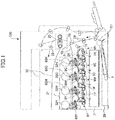
- FIG. 1 is a schematic diagram showing a part of a structure of an image forming apparatus main body 100 of an image forming apparatus according to the first embodiment of the present invention.
- toner containers 32Y, 32M, 32C, and 32K corresponding to four colors yellow, magenta, cyan, and black are detachably attached to the toner container storing section 31.
- An intermediate transfer unit 15 is provided under the toner container storing section 31.
- the intermediate transfer unit 15 includes an intermediate transfer belt 8.
- Image forming sections 6Y, 6M, 6C, and 6K corresponding to the four colors yellow, magenta, cyan, and black are positioned to face the intermediate transfer belt 8.
- Toner supplying devices 60Y, 60M, 60C, and 60K are provided under the corresponding toner containers 32Y, 32M, 32C, and 32K. Toners contained in the toner containers 32Y, 32M, 32C, and 32K are supplied to corresponding developing devices in the image forming sections 6Y, 6M, 6C, and 6K by the corresponding toner supplying devices 60Y, 60M, 60C, and 60K.
- FIG. 1 Some elements in FIG. 1 which are not described above are described below.
- FIG. 2 is a schematic diagram showing a part of a structure of the image forming apparatus main body 100 including the image forming section 6Y shown in FIG. 1 .
- the image forming section 6Y corresponding to the yellow color includes a photoconductor drum 1Y, a charging section 4Y facing the photoconductor drum 1Y, a developing device 5Y (developing section), a cleaning section 2Y, and a discharging section (not shown).
- Image forming processes (a charging process, an exposing process, a developing process, a transferring process, and a cleaning process) are performed on the photoconductor drum 1Y, and a yellow image is formed on the photoconductor drum 1Y.
- Each of the image forming sections 6M, 6C, and 6K has a structure substantially identical to the structure of the image forming section 6Y and forms a corresponding color image. Therefore, in the following, the image forming section 6Y is mainly described while omitting the descriptions of the image forming sections 6M, 6C, and 6K.
- the photoconductor drum 1Y is rotated clockwise by a driving motor (not shown). Then, the surface of the photoconductor drum 1Y is uniformly charged by the charging section 4Y (the charging process).
- the surface of the photoconductor drum 1Y reaches a position where laser beams L are radiated from an exposing device 7 (see FIG. 1 ) and an electrostatic latent image corresponding to yellow is formed at the position by being exposed by the laser beams (the exposing process).
- the surface of the photoconductor drum 1Y on which the electrostatic latent image has been formed reaches a position facing the developing device 5Y, the electrostatic latent image is developed at the position, and a yellow toner image is formed (the developing process).
- the surface of the photoconductor drum 1Y on which the toner image has been formed reaches a position facing the intermediate transfer belt 8 and a primary transfer bias roller 9Y, and the toner image on the photoconductor drum 1Y is transferred onto the intermediate transfer belt 8 at the position (a primary transferring process).
- a small amount of toners which have not been transferred onto the intermediate transfer belt 8 remain on the photoconductor drum 1Y.
- the surface of the photoconductor drum 1Y reaches a position facing the cleaning section 2Y and the toners remaining on the surface of the photoconductor drum 1Y are mechanically removed by a cleaning blade 2a (the cleaning process).
- the above image forming process is performed in the image forming sections 6M, 6C, and 6K, similar to in the image forming section 6Y. That is, the laser beams L corresponding to image information are radiated onto the corresponding photoconductor drums 1M, 1C, and 1K from the exposing device 7 positioned under the image forming sections 6M, 6C, and 6K.
- the exposing device 7 causes a light source to emit the laser beams L and radiates the laser beams L onto the corresponding photoconductor drums 1M, 1C, and 1K via plural optical elements while the laser beams L are scanned by a rotating polygon mirror.
- the toner images formed on the corresponding photoconductor drums 1Y, 1M, 1C, and 1K are transferred onto the intermediate transfer belt 8 by being superposed. With this, a color image is formed on the intermediate transfer belt 8.
- the intermediate transfer unit 15 includes the intermediate transfer belt 8, four primary transfer bias rollers 9Y, 9M, 9C, and 9K, a secondary transfer backup roller 12, plural tension rollers (not shown), and an intermediate transfer cleaning section (not shown).
- the intermediate transfer belt 8 is supported by plural rollers and is endlessly rotated in the arrow direction by the secondary transfer backup roller 12.
- Primary transfer nips are formed by sandwiching the intermediate transfer belt 8 between the four primary transfer bias rollers 9Y, 9M, 9C, and 9K and the four photoconductor drums 1Y, 1M, 1C, and 1K.
- a transfer bias voltage whose polarity is inverted relative to the polarity of the toners is applied to the four primary transfer bias rollers 9Y, 9M, 9C, and 9K.
- the intermediate transfer belt 8 sequentially passes through the primary transfer nips of the primary transfer bias rollers 9Y, 9M, 9C, and 9K by being moved in the arrow direction. With this, the toner images on the corresponding photoconductor drums 1Y, 1M, 1C, and 1K are primarily transferred onto the intermediate transfer belt 8 by being superposed.
- the intermediate transfer belt 8 onto which the toner images have been transferred by being superposed reaches a position facing a secondary transfer roller 19.
- a secondary transfer nip is formed at the position where the intermediate transfer belt 8 is sandwiched between the secondary transfer backup roller 12 and the secondary transfer roller 19.
- the four-color toner image formed on the intermediate transfer belt 8 is transferred onto a recording medium P (for example, paper) carried to the position of the secondary nip (a secondary transferring process).
- a recording medium P for example, paper
- the intermediate transfer belt 8 reaches a position facing the intermediate transfer cleaning section and the toners remaining on the intermediate transfer belt 8 are removed at the position.
- the recording medium P is carried to the position of the secondary nip from a paper feeding section 26 at a lower part of the image forming apparatus main body 100 via a paper feeding roller 27, a pair of registration rollers 28, and so on.
- the plural recording media P are stored in the paper feeding section 26 by being stacked.
- a top recording medium P is carried to a position between the pair of registration rollers 28.
- the recording medium P carried to the pair of registration rollers 28 is temporarily stopped at a roller nip position of the pair of registration rollers 28 whose rotation is stopped. Then the pair of registration rollers 28 is rotated again by matching the timing of the color image on the intermediate transfer belt 8, and the recording medium P is carried to the secondary transfer nip. With this, the color image is transferred onto the recording medium P.
- the recording medium P onto which the color image has been transferred at the position of the secondary transfer nip is carried to a fixing section 20 and the color image on the recording medium P is fixed by heat and pressure from a corresponding fixing belt and a pressure applying roller of the fixing section 20.
- the recording medium P on which the color image has been formed is output to a stacking section 30 via a pair of paper outputting rollers 29.
- the output plural recording media P are sequentially stacked on the stacking section 30.
- the developing device 5Y includes a developing roller 51Y facing the photoconductor drum 1Y, a doctor blade 52Y facing the developing roller 51Y, developer containers 53Y and 54Y, two carrying screws 55Y in the corresponding developer containers 53Y and 54Y, and a concentration detecting sensor 56Y for detecting a toner concentration in a developer G.
- the developing roller 51Y includes a magnet (not shown) secured inside the developing roller 51Y and a sleeve (not shown) which is rotated around the magnet.
- the developer G (two-component developer) formed of carrier particles (toner carrier) and toners is contained in the developer containers 53Y and 54Y.
- the developer container 54Y is connected to a toner dropping route 64Y via an opening formed at an upper side of the developer container 54Y.
- the sleeve of the developing roller 51Y is rotated in the arrow direction shown in FIG. 2 .
- the developer G carried on the developing roller 51Y by a magnetic field generated by the magnet is moved on the developing roller 51Y while the sleeve is rotated.
- the toner concentration of the developer G in the developing device 5Y is adjusted to be a value within a predetermined range. Specifically, toners contained in the toner container 32Y (see FIG. 1 ) are supplied to the developer container 54Y via the toner supplying device 60Y (see FIG. 1 ) corresponding to a consumed amount of toners in the developing device 5Y.
- the toner supplying device 60Y is described below in detail.
- the toners supplied to the developer container 54Y are mixed with the developer G in the developer container 54Y, and the developer G is circulated in the two developer containers 53Y and 54Y while the developer G is stirred by the carrying screws 55Y.
- the developer G is moved in the direction perpendicular to the plane of the paper of FIG. 2 .
- the toners in the developer G are adhered to carrier particles by a friction charge with the carrier particles and are carried on the developing roller 51Y with the carrier particles by a magnetic force formed on the developing roller 51Y.
- the developer G carried on the developing roller 51Y reaches the doctor blade 52Y by being carried in the arrow direction.
- the amount of the developer G on the developing roller 51Y is adjusted to be a suitable value by the doctor blade 52Y and the developer G whose amount is adjusted is carried to a position facing the photoconductor drum 1Y.
- the position is a developing region.
- the toners in the developer G are adhered onto an electrostatic latent image formed on the photoconductor drum 1Y by an electric field generated in the developing region.
- the developer G remaining on the developing roller 51Y reaches an upper part in the developer container 53Y by the rotation of the sleeve and the remaining developer G is dropped from the developing roller 51Y._
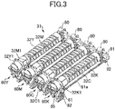
- FIG. 3 is a perspective view of a part of the structure of the image forming apparatus main body 100 including the toner container storing section 31 shown in FIG. 1 .
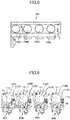
- FIG. 4 is a top view of a part of the structure of the image forming apparatus main body 100 including the toner container storing section 31 shown in FIG. 1 .
- FIG. 5 is a front view of a part of the structure of the image forming apparatus main body 100 including the toner container storing section 31 shown in FIG. 1 .
- the toners contained in the corresponding toner containers 32Y, 32M, 32C, and 32K in the toner container storing section 31 are suitably supplied to the corresponding developing devices by the corresponding toner supplying devices 60Y, 60M, 60C, and 60K based on the consumed amounts of the corresponding toners.
- each of the toner supplying devices 60Y, 60M, 60C, and 60K is substantially equal, and the structure of each of the toner containers 32Y, 32M, 32C, and 32K is substantially equal. Therefore, the toner supplying device 60Y and the toner container 32Y are described as representative.
- the toners contained in the toner container 32Y are discharged from the toner outlet W and are stored in a toner tank of the toner supplying device 60Y.
- FIG. 12 is a schematic diagram showing a state where the toner container 32Y is connected to the toner supplying device 60.
- the toner container 32Y is an approximately cylinder-shaped toner bottle, and includes a spiral protrusion on the internal circumferential surface of the toner container 32Y.
- a spiral groove is viewed.
- the driving section 71 includes a driving motor 80, a driving coupling member 90, and a gear 91 (see FIG. 6 ).
- the toner container 32Y when the toner container 32Y is suitably rotated by the driving section 71, the toners are suitably supplied to a toner tank 61Y of the toner supplying device 60.
- the service life of each of the toner containers 32Y, 32M, 32C, and 32K has passed; that is, when almost all toners in the toner container 32Y have been consumed, an old one is replaced with a new one.
- the toner supplying device 60Y includes the toner tank 61Y, a toner carrying screw 62Y, a toner carrying tube 63Y (see FIG. 13 ), a toner dropping route 64Y (see FIG. 13 ), a toner stirring member 65Y, and a toner end sensor 66Y (detecting unit).
- the toner carrying screw 62Y and the toner carrying tube 63Y form a toner carrying section (see FIG. 13 ).
- FIG. 6 is a side view of a part of the structure of the image forming apparatus main body 100 including the toner container storing section 31 shown in FIG. 1 .
- the driving section 71 includes the driving motor 80, the driving coupling member 90, and a gear train formed of gears 81 through 84 (see FIG. 14 ), 91, and 92, a driving force transmitting shaft 81a, a dropping part shutter 86, a supporting member (not shown), an antenna substrate 120 (see FIG. 10 ), a toner receiving section 85 (see FIG. 3 ), and the shutter 89 (see FIG. 18 ).
- the driving coupling member 90 for engaging with an engaging section 32Y2b (see FIG. 20 ) formed at the bottom of the toner container 32Y is positioned at the back side of the toner supplying device 60Y (at the back side of the toner container attaching direction).
- a driving force of the driving motor 80 is transmitted to the driving coupling member 90 via the gear 91 (double gear), and a container main body 32Y2 of the toner container 32Y is rotated in a predetermined direction by the driving coupling member 90.
- the gear 92 which engages with the gear 91 transmits the driving force to the gear 81 positioned at the front side of the toner supplying device 60Y via the driving force transmitting shaft 81a.
- the driving force transmitted to the gear 81 rotates the toner carrying screw 62Y and the toner stirring member 65Y via the gear train formed of the gears 81 through 84.
- the structure of the toner supplying device 60Y at the front side where the toner carrying screw 62Y and the toner stirring member 65Y are positioned is described below in detail by referring to FIGs. 12 through 18 .
- FIG. 7 is a perspective view of a part of the image forming apparatus main body 100 including the toner container storing section 31.
- FIG. 8 is a front view of a part of the image forming apparatus main body 100 when the main body cover is opened. As shown in FIG. 8 , when the main body cover is opened, an inner cover 109 is exposed in which four inserting openings 109Y, 109M, 109C, and 109K are formed. The toner containers 32Y, 32M, 32C, and 32K are inserted into the corresponding inserting openings 109Y, 109M, 109C, and 109K.
- attaching and detaching operations of the toner containers 32Y, 32M, 32C, and 32K are performed from the front side of the image forming apparatus main body 100 in the long length direction of the toner containers 32Y, 32M, 32C, and 32K.
- FIG. 9 is a front view of inserting openings into which the corresponding toner supplying devices 60Y, 60M, 60C, and 60K are inserted.
- the shapes of the inserting openings 109Y, 109M, 109C, and 109K are the same.
- the shapes of inserting openings 110Y, 110M, 110C, and 110K into which the corresponding toner supplying devices 60Y, 60M, 60C, and 60K are inserted are different from each other.
- a first guide groove 111 into which corresponding guide ribs 32Y1f, 32M1f, 32C1f, and 32K1f (see FIGs. 25 through 28 ) formed at corresponding cap sections of the toner containers 32Y, 32M, 32C, and 32K are engaged; is formed.
- second guide grooves 112Y, 112M, 112C, and 112K into which corresponding protrusion members 32Y1d and 32Y1e, 32M1d and 32M1e, 32C1d and 32C1e, and 32K1d and 32K1e (see FIGs. 25 through 28 ) formed at the corresponding cap sections of the toner containers 32Y, 32M, 32C, and 32K are engaged; are formed. That is, the shapes of the second guide grooves 112Y, 112M, 112C, and 112K are different from each other, and prevent the toner supplying devices 60Y, 60M, 60C, and 60K from being inserted into a wrong position.
- the second guide grooves 112Y, 112M, 112C, and 112K are positioned at the same sides (in FIG. 9 , at the right sides) in the corresponding inserting openings 110Y, 110M, 110C, and 110K, when a virtual vertical line Q passing through the center of the first guide grove 111 is determined to be a reference. That is, the protrusion members 32Y1d and 32Y1e, 32M1d and 32M1e, 32C1d and 32C1e, and 32K1d and 32K1e which are different from each other are positioned near the corresponding guide ribs 32Y1f, 32M1f, 32C1f, and 32K1f.
- the second guide grooves 112Y, 112M, 112C, and 112K in the corresponding inserting openings 110Y, 110M, 110C, and 110K are positioned at the right sides in FIG. 9 ; the distance between the adjacent two of the inserting openings 110Y, 110M, 110C, and 110K can be relatively small.
- a stopped part 113 having a groove shape is formed in each of the inserting openings 110Y, 110M, 110C, and 110K into which the corresponding toner supplying devices 60Y, 60M, 60C, and 60k are inserted.
- a stopping part 32Y1a3 of a shutter member 32Y1a (see FIGs. 40 , 42, and 43 ) of the toner container 32Y is engaged into the stopped part 113.
- the toner container 32Y when the toner container 32Y is attached to or detached from the image forming apparatus main body 100, the movement of the toner container 32Y in the short length direction (the lateral direction of the paper of FIG. 9 ) of the toner container 32Y can be prevented.
- a user rotates a cap section 32Y1 by grasping a handle part 32Y1b (see FIGs.
- the toner container 32Y can be normally attached to the toner supplying device 60Y.
- FIG. 10 is a perspective view of the toner container storing section 31.
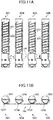
- FIG. 11A is a plan view of the toner supplying devices 60Y, 60M, 60c and 60K to which the corresponding toner containers 32Y, 32M, 32C, and 32K are attached.
- FIG. 11B is a front view of the toner supplying devices 60Y, 60M, 60c and 60K to which the corresponding toner containers 32Y, 32M, 32C, and 32K are attached.
- the toner containers 32Y, 32M, 32C, and 32K are detachably attached to the corresponding toner supplying devices 60Y, 60M, 60C, and 60K.
- the antenna substrate 120 is positioned on a supporting part 115 of the toner container storing section 31.
- antennas 121Y, 121M, 121C, and 121K are positioned on a surface of the antenna substrate 120.
- the four antennas 121Y, 121M, 121C, and 121K communicate with corresponding electronic substrates 32Y1c, 32M1c, 32C1c, and 32K1c (see FIGs. 25 through 28 ) positioned on the circumferential surfaces of the corresponding toner containers 32Y, 32M, 32C, and 32K.
- the antenna substrate 120 is under the toner containers 32Y, 32M, 32C, and 32K positioned on the supporting part 115 of the toner container storing section 31.
- the information to be communicated with each other is, for example, the production serial number of the toner container, the recycled number of the toner container, the kind of toners, the production lot number of toners, the production date of toners, the manufacturer of toners, the amount of toners in the toner container, the color of toners, and a usage history of the image forming apparatus main body 100.
- the electronic substrates 32Y1c, 32M1c, 32C1c, and 32K1c face the corresponding antennas 121Y, 121M, 121C, and 121K; the communications between the electronic substrates 32Y1c, 32M1c, 32C1c, and 32K1c and the corresponding antennas 121Y, 121M, 121C, and 121K are performed in good conditions.
- the antennas 121Y, 121M, 121C, and 121K are positioned under the supporting part 115 of the toner storing section 31, the toner supplying device 60Y, 60M, 60C, and 60K (the image forming apparatus main body 100) are not large sized in the long length direction. With this, cost of components to be used in the image forming apparatus main body 100 and manufacturing cost of the image forming apparatus main body 100 can be relatively low, and the installing capability of the image forming apparatus main body 100 in an office can be increased.
- FIG. 32 is a schematic diagram showing a head part of the toner container 32Y attached to the toner supplying device 60Y.
- the antenna substrate 120 (the antenna 121Y) is positioned at the right side of the toner outlet W of the toner container 32Y. Even if toners are leaked from the toner outlet W, the toners are dropped to the left side of the image forming apparatus main body 100.
- the toner outlet W is separated from the antenna substrate 120 and the electronic substrate 32Y1c facing the antenna substrate 120 by the inserting opening 110Y (see FIG. 9 ). Therefore, the toners are hardly dropped on the antenna substrate 120 directly. Consequently, the decrease of the communication sensitivity due to the drop of the toners at a position between the electronic substrate 32Y1c and the antenna 121Y can be prevented.
- the electronic substrate 32Y1c of the toner container 32Y is positioned to face the antenna substrate 120, the electronic substrate 32Y1c is positioned at the back side relative to the position of the toner outlet W.
- the electronic substrate 32Y1c is positioned at the back side of the toner supplying opening 60Ya of the image forming apparatus main body 100. Therefore, when the toner container 32Y is attached to or detached from the toner supplying device 60Y, the electronic substrate 32Y1c passes through an adjacent position over the toner supplying opening 60Ya. Consequently, there is a risk that the electronic substrate 32Y1c is contaminated by a small amount of a powder smoke of the toners.
- the shutter 89 (the main body side shutter) closes the toner supplying opening 60Ya.
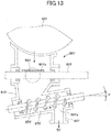
- FIG. 13 is a cut-away side view of the toner supplying device 60Y.
- FIG. 14 is an external side view of the toner supplying device 60Y.
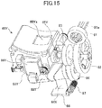
- FIG. 15 is a perspective view of the toner supplying device 60Y.
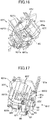
- FIG. 16 is a perspective view of the toner supplying device 60Y when the toner supplying opening 60Ya is opened.
- FIG. 17 is another perspective view of the toner supplying device 60Y when the toner supplying opening 60Ya is opened.
- FIG. 18 is a perspective view of the toner supplying device 60Y when the shutter 89 is attached to a position of the toner supplying opening 60Ya.
- the toner supplying device 60Y includes the toner tank 61Y, the toner carrying screw 62Y, the toner carrying tube 63Y, the toner dropping route 64Y, the toner stirring member 65Y, the toner end sensor 66Y (detecting unit), the gear train formed of the gears 81 through 84, the toner receiving section 85, the shutter 89 (main body side shutter).
- the shutter 89 is only shown in FIGs. 18 and 34 , and is omitted in the other drawings.
- the toner tank 61Y is under the toner outlet W of the cap section 32Y1 of the toner container 32Y and stores the toners discharged from the toner outlet W of the toner container 32Y via the toner supplying opening 60Ya.
- the bottom part of the toner tank 61Y is connected to an upstream side of a toner carrying section (the toner carrying screw 62Y and the toner carrying tube 63Y).
- the toner end sensor 66Y is on a wall surface of the toner tank 61Y at a position having a predetermined height from the bottom surface of the toner tank 61Y.
- the toner end sensor 66Y detects a signal when the amount of the toners stored in the toner tank 61Y becomes a value less than a predetermined value.
- a piezoelectric sensor can be used as the toner end sensor 66Y.
- the controlling section 70 controls the driving section 71 (the driving motor 80, the driving coupling member 90, and the gear 91 (see FIG. 6 )) to rotate the toner container 32Y for a predetermined period so as to supply toners to the toner tank 61Y.
- the controlling section 70 determines that no toners remain in the toner container 32Y. Then the controlling section 70 displays a message which instructs to replace the existing toner container 32Y with a new one on a displaying section (not shown) of the image forming apparatus main body 100.
- the toner stirring member 65Y (rotating member) is at an inner center position of the toner tank 61Y near the toner end sensor 66Y for preventing the toners stored in the toner tank 61Y from being condensed.
- the toner stirring member 65Y includes a flexible member 65Ya, and rotates in the arrow direction clockwise as shown in FIG. 12 , and stirs the toners in the toner tank 61Y.
- the gear 82 (a bevel gear) having a twisting angle of 45 degrees is attached to one end of the shaft of the toner stirring member 65Y, and a driving force is transmitted to the toner stirring member 65Y via the gear 81 (a bevel gear) having a twisting angle of 45 degrees engaged with the bevel gear 82.
- the toner carrying screw 62Y and the toner carrying tube 63Y carry the toners stored in the toner tank 61Y in the obliquely upward direction (the arrow direction). Specifically, the toner carrying screw 62Y and the toner carrying tube 63Y linearly carry the toners from the bottom part (the lowest part) of the toner tank 61Y to a position above the developing device 5Y (a toner dropping opening 64Ya of the toner dropping route 64Y). The toners reaching the toner dropping opening 64Ya are supplied to the developer container 54Y (see FIG. 2 ) of the developing device 5 by the toner's own weight via the toner dropping route 64Y.
- the toner carrying screw 62Y carries the toners by being rotated in a predetermined direction, and the toner carrying tube 63Y has an inner wall adjacent to the toner carrying screw 62Y.
- the toner carrying section includes the toner carrying screw 62Y and the toner carrying tube 63Y.
- the toner carrying screw 62Y is a screw member in which a helicoid is spirally formed on a shaft and is rotatably supported in the toner carrying tube 63Y via bearings (not shown).
- the gear (skew gear) 84 is attached to one end of the toner carrying screw 62Y, and a driving force is transmitted to the toner carrying screw 62Y via the gear 83 (skew gear) attached to the shaft of the toner stirring member 65Y in which the gear 83 is engaged with the gear 84.
- the upstream side of the toner carrying tube 63Y is connected to the toner tank 61Y and the downstream side of the toner carrying tube 63Y is connected to the toner dropping route 64Y via the toner dropping opening 64Ya (see FIG. 13 ).
- the toner carrying tube 63Y is a tube-shaped member formed of a resin material.
- the toner carrying screw 62Y (screw member) is rotatably supported in the toner carrying tube 63Y via a bearing.
- the gap between the external diameter of the toner carrying screw 62Y and the inner wall of the toner carrying tube 63Y is determined to be approximately 0.1 to 0.2 mm. With this, the toners are smoothly carried in the obliquely upward direction against the gravitational force by the toner carrying screw 62Y and the toner carrying tube 63Y.
- the toners stored in the toner tank 61Y are carried in the obliquely upward direction by the toner carrying screw 62Y and the toner carrying tube 63Y, and the carried toners are supplied to the developing device 5Y by the toner's own weight via the toner dropping route 64Y.
- the toner carrying screw 62Y is stopped when the supply of the toners to the developing device 5Y is stopped, the toners remaining in the toner carrying tube 63Y are hardly dropped into the developing device 5Y via the toner dropping route 64Y.
- the toners remaining at a position separated from the toner dropping opening 64Ya slide toward the toner tank 61Y along the oblique toner carrying tube 63Y or stay at the position.
- the toners remaining at a position near the toner dropping opening 64Ya in the toner carrying tube 63Y are not greatly dropped from the toner dropping opening 64Ya by the toner's own weight even if the apparatus is subjected to a great shock, and the toners slide toward the toner tank 61Y along the oblique toner carrying tube 63Y or stay at the position.
- the amount of toners to be supplied to the developing device 5Y can be controlled at high accuracy; that is, the toners can be stably supplied to the developing device 5Y. Consequently, the variation of the toner concentration in the developer G can be prevented. That is, the image density of an output image can be prevented from being high, the toners can be prevented from being scattered, and the background image can be prevented from being degraded.
- the inclination angle ⁇ of the toner carrying screw 62Y and the toner carrying tube 63Y relative to the horizontal direction be 5 or more degrees ( ⁇ ⁇ 5 °).
- the inclination angle ⁇ is determined to be approximately 10 degrees.
- the dropping part shutter 86 is attached to the toner dropping route 64Y, and the dropping part shutter 86 is opened or closed when the developing device 5Y is attached to or detached from the image forming apparatus main body 100.
- the dropping part shutter 86 moves to open the toner dropping route 64Y by being pushed by the developing device 5Y against a force of a spring 87.
- the dropping part shutter 86 moves to close the toner dropping route 64Y by the force of the spring 87.
- a seal member formed of a hair implantation seal 67Y, a sponge seal 68Y2, a sheet-shaped member 68Y3, and so on is adhered onto a part surrounding the toner supplying opening 60Ya of the toner tank 61Y.
- the sponge seal 68Y2 contacts a flange W2 of the toner outlet W (see FIG. 23 ) of the toner container 32Y and obtains the sealing capability between the toner tank 32Y and the toner tank 61Y.
- the sheet-shaped member 68Y3 is formed of a low friction material, contacts the shutter member 32Y1a (see FIG.
- the hair implantation seal 67Y scrapes the toners adhered onto the surface of the shutter member 32Y1a with the detaching operation of the toner container 32Y from the image forming apparatus main body 100.
- the toners scraped by the hair implantation seal 67Y are dropped into the toner receiving section 85 via an opening 85a where a round surface 60Yc is formed.
- Supply opening guides 69Y are at positions which sandwich the toner supplying opening 60Ya of the toner tank 61Y.
- the supply opening guides 69Y guide the flange W2 of the toner outlet W (see FIG. 23 ) and prevent the toner outlet W from being moved in the upward direction from the toner supplying opening 60Ya.
- the shutter 89 main body side shutter
- the shutter 89 which opens or closes the toner supplying opening 60Ya connecting to the toner outlet W of the toner container 32Y (see FIG. 23 )
- the shutter 89 is formed to have a curve so that the shutter 89 fits the circumferential surface of the toner container 32Y (the cap section 32Y1).
- the toner supplying device 60Y includes a sliding surface (not shown) on which the shutter 89 slides in the circumferential direction of the toner supplying device 60Y. In order to fill a gap between the sliding surface and the shutter 89, a sealing member can be adhered onto the sliding surface.
- the shutter 89 opens or closes the toner supplying opening 60Ya by being pushed by the cap section 32Y1 (a guiding member 32Y1g and a contacting section 32Y1h) together with an opening or closing operation of the shutter member 32Y1a. With this, the toner outlet W of the toner container 32Y is connected to the toner supplying opening 60Ya of the toner supplying device 60Y.
- the antenna substrate 120 (see FIG. 10 ) is positioned at the back side in the attaching direction (the right side of FIG. 32 ) of the toner containers 32Y, 32M, 32C, and 32K arrayed on the supporting part 115 of the toner container storing section 31. Therefore, toners are hardly dropped on the antenna 121 directly.
- the antenna 121Y since the antenna 121Y communicates with the electronic substrate 32Y1c without contact, the powder smoke of the toners are prevented from being dropped on the antenna 121Y as described below.
- a brim section 31Ya is positioned to cover the antenna 121Y. That is, when the toner container 32Y is attached to the toner supplying device 60Y in the dotted-line arrow direction, the brim section 31Ya is positioned between the antenna 121Y and the electronic substrate 32Y1c, and communications are performed between the antenna 121Y and the electronic substrate 32Y1c.
- Brim sections (not shown) are positioned between the antenna substrate 120 and the corresponding antennas 121M, 121C, and 121K.
- a partition section 31Yb is positioned between the toner supplying opening 60Ya to be connected to the toner outlet W of the toner container 32Y (the cap section 32Y1) and the brim section 31Ya.
- the partition section 31Yb is a wall member whose height is greater than the heights of the toner supplying opening 60Ya and the brim section 31Ya in the vertical direction. Therefore, the toners are prevented from flowing from the toner supplying opening 60Ya to the brim section 31Ya.
- the brim section 31Ya is formed to be a curved surface so that the circumferential surface of the toner container 32Y (the cap section 32Y1) fits the curved surface. That is, wall sections 31Ya1 are formed to cover the circumferential surface of the toner container 32Y (the cap section 32Y1) at both ends of the brim section 32Ya in the short length direction of the brim section 31Ya. In FIG. 44 , one of the wall sections 31Ya1 is shown. With this, toners are prevented from flying to an adjacent antenna. Specifically, when the wall sections 31Ya1 are formed to the brim section 31Ya, the antenna 121M adjacent to the antenna 121Y is prevented from being contaminated by flying of the toners from the toner container 32Y.
- the toner container 32Y can be smoothly attached to or detached from the toner supplying device 60Y by being guided with the brim section 31Ya. With this, vibrations of the toner containers 32Y at the attaching or detaching operation of the toner container 32Y can be decreased, and toners adhered onto the toner container 32Y can be prevented from being flown and dropped.
- the inventors of the present embodiment have performed an experiment.
- the toner container 32Y containing 200 g of toners was attached to and detached from the toner supplying device 60Y 30 times, and an amount of toners dropped and adhered onto the antenna 121Y was measured.
- the toners adhered onto the antenna 121Y were collected on a transparent tape, and the toners on the transparent tape were optically measured by using an ID measuring instrument X-Rite. When the ID value measured by the ID measuring instrument is great, the amount of adhered toners is great.
- the ID value when the brim section 31Ya was not the curved surface, the ID value was 0.09, when the brim section 31Ya was not the curved surface and the partition section 31Yb was formed, the ID value was 0.04, and when the brim section 31Ya was the curved surface and the partition section 31Yb was not formed, the ID value was 0.06. Further, when the brim section 31Ya was not formed, the ID value was 0.98. Therefore, when the brim section 31Ya was formed, an excellent effect was obtained.
- the toner container 32Y is a cylindrical container, and includes the cap section 32Y1 and the container main body 32Y2.
- the container main body 32Y2 includes an opening section and the opening section is connected to the inside of the cap section 32Y1.
- a spiral protrusion 32Y2a is formed on the inner wall of the container main body 32Y2.
- the container main body 32Y2 is rotated in a predetermined direction by receiving a driving force from the driving coupling member 90 of the image forming apparatus main body 100 for engaging with the engaging sections 32Y2b formed at the bottom of the toner container 32Y. With this, toners in the toner container 32Y are carried toward the cap section 32Y1.
- the toners discharged from the opening section of the container main body 32Y2 are output from the toner outlet W formed at the circumferential surface of the cap section 32Y1, and are supplied to the toner tank 61Y of the toner supplying device 60Y via the toner supplying opening 60Ya (see FIGs. 32 through 34 ).
- two scrapers 32Y30 are positioned at the opening section of the container main body 32Y2.
- the scrapers 32Y30 are rotated together with the container main body 32Y2, and effectively move the toners near the opening section of the container main body 32Y2 to the side of the cap section 32Y1.
- the two engaging sections 32Y2b for engaging with claw members of the driving coupling member 90 of the image forming apparatus main body 100 are positioned by having a distribution angle of 180 degrees with the rotational center axis of the container main body 32Y2 as the reference.
- the number of the engaging sections 32Y2b of the toner container 32Y can be three or more by forming the three or more claw members of the driving coupling member 90 of the image forming apparatus main body 100 in which the distribution angle is determined to be a suitable angle with the rotational center axis of the container main body 32Y2 as the reference.
- torque variation can be decreased.
- a probability may be increased in which the engaging sections 32Y2b interfere with the claw members when the toner container 32Y is attached to the image forming apparatus main body 100.
- the number of the engaging sections 32Y2b and the claw sections must be determined by considering the toner outputting capability from the toner container 32Y determined by the torque variation and the attaching capability of the toner container 32Y to the image forming apparatus 100 determined by the interference between the engaging sections 32Y2b and the claw sections.
- the cap section 32Y1 When the toner container 32Y is attached to the toner supplying device 60Y, the cap section 32Y1 is secured to the toner supplying device 60Y. That is, after attaching the toner container 32Y to the toner supplying device 60Y, the cap section 32Y1 is not rotated, and only the container main body 32Y2, which is rotatably supported by the cap section 32Y1, is rotated.
- the sealing capability between the cap section 32Y1 and the container main body 32Y2 is obtained by a sealing member 32Y20b (see FIG. 29 ) adhered onto a handle main body 32Y20. That is, as shown in FIG. 24 , since the opening section of the container main body 32Y2 breaks into the sealing member 32Y20b of the cap section 32Y1, the toners are prevented from being leaked from a position between the cap section 32Y1 and the container main body 32Y2.
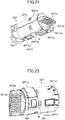
- the cap section 32Y1 includes the toner outlet W, the shutter member 32Y1a, the guiding member 32Y1g, the contacting section 32Y1h, a pushing member 32Y1k, the electronic substrate 32Y1c, a protrusion member 32Y1d (a non-compatible identification member), a rib 32Y1e (a color identifying rib), the guide rib 32Y1f, the handle part 32Y1b, and an elastic member 125 (see FIG. 35 ).
- the guiding member 32Y1g includes a protrusion W1 and the flange W2.
- the cap section 32Y1 is formed by engaging a cap section main body 32Y10 with the handle main body 32Y20 (see FIG. 29 ), and the cap section main body 32Y10 is adhered to the handle main body 32Y20 by using the rib 32Y20c as the adhering surface.
- the shutter member 32Y1a opens or closes the toner outlet W when the toner container 32Y is attached to or detached from the toner supplying device 60Y.
- the toner container 32Y is attached to the toner supplying device 60 (the image forming apparatus main body 100)
- a user inserts the container main body 32Y2 of the toner container 32Y into the inserting opening 110Y (see FIG. 9 ) of the image forming apparatus main body 100 from the bottom section of the container main body 32Y2 while holding the handle part 32y1b of the toner container 32Y.
- the rotation of the cap section 32Y1 is stopped by engaging the inserting opening 110Y and the guide rib 32Y1f on the cap section main body 32Y10 with a first guide groove 111Y.
- the protrusion member 32Y1d and the rib 32Y1e exceed the second guide grooves 112Y.
- the protrusion member 32Y1d is engaged with a stopping member of the toner supplying device 60Y, the toner container 32Y is stopped, and the toner outlet W is opened.
- the toner outlet W engages with toner supplying opening 60Ya of the toner tank 61Y (see FIGs. 32 through 34 ), and the cap section 32Y1 is secured to the toner supplying device 60Y.
- the toner supplying opening 60Ya is opened when the shutter 89 of the toner supplying device 60Y is pushed by the cap section 32Y1 by the movement of the shutter member 32Y1a (the rotation of the cap section 32Y1 of the toner container 32Y) (see FIGs. 18 and 34 ).
- a concave section 32Y1b1 is formed in the upper surface of the handle part 32Y1b and a concave section 32Y20a is formed under the handle part 32Y1b in the handle main body 32Y20.
- the guiding member 32Y1g is formed to surround the toner outlet W in the cap section 32Y1 so as to protrude from the circumferential surface of the cap section 32Y1.
- the guiding member 32Y1g is formed to engage with a grove (see FIG. 35 ) formed in the inner wall of the shutter member 32Y1a, and guides the opening or closing operation of the shutter member 32Y1a in the circumferential direction.
- the guiding member 32Y1g includes the protrusion W1 and the flange W2 to surround the protrusion W1.
- the protrusion W1 breaks into the elastic member 125 (see FIG. 35 ) adhered onto the back surface of the shutter member 32Y1a, and provides a good sealing capability between the toner outlet W and the shutter member 32Y1a.
- the protrusion W1 breaks into a sealing member (not shown) adhered onto a surrounding part of the toner supplying opening 60Ya (see FIG. 18 ), and provides a good sealing capability between the toner outlet W and the toner supplying opening 60Ya.
- the electronic substrate 32Y1c has a function of, for example, an RFID, and as described above, communicates with the antenna substrate 120 (see FIG. 10 ) for communicating information between the toner container 32Y and the image forming apparatus main body 100.
- the protrusion member 32Y1d prevents a different type of toner container from being attached to the image forming apparatus main body 100 in the long length direction. For example, when a manufacturer produces an image forming apparatus under a model name of another company, and supplies a toner container under the name of the company, the protrusion member 32Y1d is formed to identify the toner container 32Y. The protrusion member 32Y1d is formed to sandwich the electronic substrate 32Y1c with the shutter member 32Y1a when the toner outlet W is closed.
- the protrusion member 32Y1d includes three protrusions right after the molding.
- the breaking position of the protrusion is different between the toner containers.
- the protrusion at the upper position is broken for a first company and the protrusions at the upper and lower positions are broken for a second company.
- the shape of the grove, through which the protrusion member 32Y1d passes, is changed in the image forming apparatus main body 100.
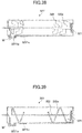
- the protrusion member 32Y1e is formed so that the toner container 32M, 32C, or 32K different from the toner container 32Y is not wrongly inserted into the inserting opening 110Y of the toner supplying device 60Y (see FIG.9 ). That is, ribs of the protrusion member 32Y1e shown in FIG. 25 , ribs of the protrusion member 32M1e shown in FIG. 26 , ribs of the protrusion member 32C1e shown in FIG. 27 , and ribs of the protrusion member 32K1e shown in FIG. 28 are positioned different from each other.
- protrusion members 32Y1e, 32M1e, 32C1e, and 32K1e are engaged with the corresponding second guide groove 112Y, 112M, 112C, and 112K of the inserting openings 110Y, 110M, 110C, and 110K (see FIG. 9 ).
- the guide ribs 32Y1f, 32M1f, 32C1f, and 32K1f guide the corresponding toner containers 32Y, 32M, 32C, and 32K to the inserting openings 110Y, 110M, 110C, and 110K of the toner supplying devices 60Y, 60M, 60C, and 60K with normal positioning.
- the shutter member 32Y1a When the shutter member 32Y1a has closed the toner outlet W (states shown in see FIG. 19 and 24 ) and the toner container 32Y is put on an arbitrary flat surface (for example, a floor), the shutter member 32Y1a and a part of the toner container 32Y form supporting points, and the electronic substrate 32Y1c does not contact the floor.
- the electronic substrate 32Y1c is inside a projection region of the toner container 32Y including the shutter member 32Y1a viewed from the long length direction.
- the electronic substrate 32Y1c is positioned by being sandwiched between the shutter member 32Y1a and the protrusion member 32Y1d. With this, the shutter member 32Y1a and the protrusion member 32Y1d form the supporting points and the electronic substrate 32Y1c does not contact the flat surface. That is, in FIG. 24 , the electronic substrate 32Y1c is positioned in a region which does not exceed a virtual dotted line S connecting the shutter member 32Y1a to the protrusion member 32Y1d.
- the shutter member 32Y1a and the protrusion member 32Y1d form the supporting points and the electronic substrate 32Y1c does not contact the flat surface. Therefore, the electronic substrate 32Y1c is prevented from being broken, the image forming apparatus is prevented from being large sized in the inserting direction of the toner container 32Y, and the sensitivity of the communications between the electronic substrate 32Y1c and the antenna 121Y of the image forming apparatus main body 100 is not restricted.
- the guide rib 32Y1f extends in the long length direction of the cap section main body 32Y20, and also functions not to rotate the cap section main body 32Y20 (the toner container 32Y) in the circumferential direction of the toner container 32Y.
- the shutter member 32Y1a functions as a stopper
- the guide rib 32Y1f functions as a stopper. With this, the rotational range of the toner container 32Y is restricted.
- the length of the guide rib 32Y1f is formed to include the length of the electronic substrate 32Y1c and the length of the protrusion member 32Y1e in the horizontal direction.
- the elastic member 125 is adhered on the back surface of the shutter member 32Y1a and faces the toner outlet W when the toner outlet W is closed, and also functions to absorb an external force when the external force is applied to the shutter member 32Y1a.
- the electronic substrate 32Y1c does not contact a flat surface by the supporting points formed by the shutter member 32Y1a and the protrusion member 32Y1d when the toner container 32Y is put on the flat surface. With this, even if the elastic member 125 is deformed by an external force, the electronic substrate 32Y1c can be prevented from being broken.
- the antenna substrate 120 is formed in which the antennas 121Y, 121M, 121C, and 121K for facing the electronic substrates 32Y1c, 32M1c, 32C1c, and 32K1c positioned on the corresponding circumferential surfaces of the toner containers 32Y, 32M, 32C, and 32K are formed on the supporting part 115.
- the image forming apparatus main body 100 (the toner supplying devices 60Y, 60M, 60C, and 60K) is not caused to be great in the toner container inserting direction, can be manufactured at low cost with relatively low-cost components, and the assembling ability of the image forming apparatus main body 100 can be high.
- the guiding member 32Y1g is formed to surround the toner outlet W so as to protrude from the toner outlet W in the cap section 32Y1 of the toner container 32Y.
- the guiding member 32Y1g is engaged with a groove (not shown) formed in the inner wall of the shutter member 32Y1a, and guides the shutter member 32Y1a so that the shutter member 32Y1a moves in the circumferential direction of the toner container 32Y (the shutter member 32Y1a opens (closes) the toner outlet W.
- the shutter member 32Y1a is surely engaged with the shutter 89, and the shutter 89 is surely opened by interfacing with the opening operation of the shutter member 32Y1a (the rotational operation of the cap section 32y1). With this, an abnormal connection of the toner outlet W with the toner supplying opening 60Ya can be prevented.
- toners dropped from the toner container 32Y to a part surrounding the toner supplying opening 60Ya are hidden by the shutter 89, stains caused by the dropped toners is hardly visible by the user when the toner container 32Y is replaced with a new one. Thus, an unsatisfying impression is not given to the user.
- the pushing member 32Y1k in addition to the end surface 32Y1g1, the pushing member 32Y1k is formed which pushes the shutter 89 together with the end surface 32Y1g1 when the shutter member 32Y1a opens the toner outlet W.
- the pushing member 32Y1K is a step formed in the circumferential surface of the cap section 32Y1 so that the surface of the step becomes the same level as the end surface 32Y1g1 of the guiding member 32Y1g.
- the pushing member 32Y1k pushes the shutter 89 (see FIG. 18 ) together with the end surface 32Y1g1 of the guiding member 32Y1g in contact with the end part 89a of the shutter 89 by moving with the opening operation of the shutter member 32Y1.
- the shutter 89 is pushed in a balanced manner by forming the pushing member 32Y1k.
- the shape of the pushing member 32Y1k is not limited to that shown in FIG. 22 , and can be, for example, an erect pin on the circumferential surface of the cap section 32Y1.
- the contacting section 32Y1h is formed to protrude from the circumferential surface of the cap section 32Y1 of the toner container 32Y.
- the contacting section 32Y1h contacts an end part 89b of the shutter 89 which contacts the end surface 32Y1g1 of the guiding member 32Y1g, and supports the shutter 89 by sandwiching with guiding member 32Y1g.
- the shutter member 32Y1a is closed (the toner outlet W is closed)
- the contacting section 32Y1h pushes the shutter 89, and the toner supplying opening 60Ya is closed.
- a brim section 32Y1a1 extending in the long length direction of the toner container 32Y is formed in the shutter member 32Y1a.
- the brim section 32Y1a1 covers the opening 85a of the toner receiving section 85 (see FIG. 33 ) when the toner container 32Y is attached to the toner supplying device 60Y. With this, toners collected in the toner receiving section 85 are not visible from the user, and as a result, an unsatisfying impression is not given to the user.
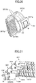
- the brim section 32Y1a1 is not shown in the drawings other than in FIGs. 19 , 22 , 33 , and 41 .
- the brim section 32Y1a1 extends to protrude in the right direction (the detaching direction of the toner container 32Y) from the cap section 32Y1 so that the circumferential surface of the shutter member 32Y1a extends to have the same curvature factor as the curvature factor of the circumferential surface of the cap section 32Y1.
- toners collected in the toner receiving section 85 cannot be viewed by the user who attaches the toner container 32Y to the toner supplying device 60Y. That is, as shown in FIG. 47 , when the brim section 32Y1a1 is not formed in the toner container 32Y, toners in the toner receiving section 85 are visible by the user, and an unsatisfying impression may be given to the user.
- protrusions 32Y1a10 are formed in the brim section 32Y1a1 of the shutter member 32Y1a so that the shutter member 32Y1a is prevented to be assembled with the toner container 32Y (the cap section 32Y1) in the wrong direction.
- the protrusions 32Y1a10 are formed so that the wall surfaces of the shutter member 32Y1a extend from the end surface of the cap section 32Y1.
- the shutter member 32Y1a in a case where the shutter member 32Y1a is assembled with the cap section 32Y1 to be guided by a guiding member (not shown) formed in the cap section 32Y1, when the shutter member 32Y1a is assembled in a wrong direction, the protrusions 32Y1a10 are run on the circumferential surface of the cap section 32Y1, and the shutter member 32Y1a cannot be assembled with the cap section 32Y1. That is, the shutter member 32Y1a is formed to assemble with the cap section 32Y1 in only the one direction (the right direction). With this, the productivity of the toner container 32Y can be increased.
- a control unit is formed in the shutter member 32Y1a so that the toner outlet W is not opened when a force other than a predetermined external force is applied to the shutter member 32Y1a.
- the control unit includes an elastic part 32Y1a2 formed on a side wall of the shutter member 32Y1a and a slope part 32Y1p formed on the circumferential surface of the cap section 32Y1. Notches are formed at the both sides of the elastic part 32Y1a2 and when a force exceeding the predetermined external force is applied to the shutter member 32Y1a, the elastic part 32Y1a2 is bent independently from the main part of the shutter member 32Y1a.
- the height of the slope part 32Y1p is first gradually increased and then gradually decreased in the circumferential direction, and is positioned near the elastic part 32Y1a2 when the shutter member 32Y1a closes the toner outlet W.
- the elastic part 32Y1a2 runs over the slope part 32Y1p by being deformed. That is, when a force having a predetermined amount or more is not applied to the shutter member 32Y1a, the elastic part 32Y1a2 does not run over the slope part 32Y1p, and the toner outlet W is not opened.
- toners in the toner container 32Y are prevented from being leaked in cases in which a small external force is applied to the shutter member 32Y1a of the toner container 32Y during the transportation of the toner container 32Y and a user accidentally touches the shutter member 32Y1 of the toner container 32Y.
- the overlapping amount (the running over amount) between the elastic part 32Y1a2 and the slope part 32Y1p is determined to be approximately 0.1 to 1.0 mm.
- two protrusions 32Y1a4 are formed on the circumferential surface of the cap section 32Y1 at positions separated from each other.
- the protrusions 32Y1a4 support the shutter member 32Y1a by two points at the back side orthogonal to the opening and closing direction of the shutter member 32Y1a (the right side in FIG. 41 ).
- the brim section 32Y1a1 is formed to cover the opening 85a of the toner receiving section 85 in the shutter member 32Y1a which opens or closes the toner outlet W in a attaching or detaching state of the toner container 32Y to or from the toner supplying device 60Y.
- the guiding section 32Y1g enters into the toner supplying device 60Y.
- the shutter member 32Y1a of the toner container 32Y is surely engaged with the shutter 89 (of the main body side).
- the thickness of the shutter 89 is determined to be the distance H2 or less.
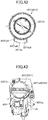
- inner walls of the cap section 32Y1 are formed of a ceiling surface 32Y1h, a slant surface 32Y1n, and a vertical surface 32Y1k.
- the ceiling surface 32Y1h is formed of a part of a cylindrical surface. That is, the inner walls of the cap section 32Y1 (supported section) do not include a horizontal surface.
- the slant surface 32Y1n toward the toner outlet W is formed at the head part and the inner walls other than the ceiling surface 32Y1n are vertical walls.
- toners hardly remain in the cap section 32Y1 when the toners have been almost consumed (at the toner end time). Specifically, when the remaining amount of toners in the toner container 32Y becomes small, toners on the slant surface 32Y1n slide down and are discharged from the toner outlet W.
- the angle ⁇ of the slant surface 32Y1n is preferably to be the repose angle of the toners or more.
- a visual line of an operator (user) is shown.
- the end surface 32Y1g1 of the guiding member 32Y1g pushes the shutter 89 together with the opening operation of the shutter member 32Y1a.
- the toner supplying opening 60Ya of the toner supplying device 60Y is opened, and the toner outlet W of the toner container 32Y is connected to the toner supplying opening 60Ya. Therefore, toners are smoothly supplied to the toner supplying device 60Y from the toner container 32Y. Even if toners are dropped from the toner container 32Y to a part surrounding the toner supplying opening 60Ya, the dropped toners are not visible from a user, and the unsatisfying impression is not given to the user.
- the antennas 121Y, 121M, 121C, and 121K for facing the electronic substrates 32Y1c, 32M1c, 32C1c, and 32K1c positioned on the corresponding circumferential surfaces of the toner containers 32Y, 32M, 32C, and 32K arrayed on the supporting part 115 of the image forming apparatus main body 100 are positioned on the antenna substrate 120.
- the image forming apparatus main body 100 (the toner supplying devices 60Y, 60M, 60C, and 60K) is not caused to be great in size in the toner container inserting direction, and as a result, can be manufactured at low cost with relatively low-cost components, and the assembling efficiency of the image forming apparatus main body 100 can be high.
- FIG. 36 is a perspective view of a toner container according to the second embodiment of the present invention
- FIG. 37 is a cut-away side view of a head part of the toner container shown in FIG. 36 .
- the same reference number 32Y as that in the first embodiment of the present invention is used.
- the head part of the toner container 32Y has a circular cone shape, and the scrapers 32Y30 are not positioned at the opening of the container main body 32Y2.
- the toner container 32Y includes the cap section 32Y1 and the container main body 32Y2 as relatively large components.
- the head part of the container main body 32Y has the circular cone shape toward the opening of the container main body 32Y2.
- an inclination angle ⁇ 2 of a spiral-shaped protrusion 32Y2a formed at the circular cone-shaped part is smaller than an inclination angle ⁇ 1 of a spiral-shaped protrusion 32Y2a formed at the other parts of the container main body 32Y2 ( ⁇ 1 > ⁇ 2).
- the toners are led to the position of the inner diameter position of the sealing member 32Y20b of the cap section 32Y1 from the opening of the container main body 32Y2 on a slope, and the toners are smoothly carried to the toner outlet W. Therefore, the toners can be carried to the toner outlet W without including the scrapers 32Y30.
- the scrapers 32Y30 are effective to stir the toners at positions surrounding the toner outlet W and the opening of the container main body 32Y2.
- the cap section 32Y1 of the toner container 32Y includes the toner outlet W, the shutter member 32Y1a, the guiding member 32Y1g, the contacting section 32Y1h, the pushing member 32Y1k, the electronic substrate 32Y1c, the protrusion member 32Y1d, the protrusion member 32Y1e, the guide rib 32Y1f, the handle part 32Y1d, the elastic member 125, the brim section 32Y1a1, the elastic part 32Y1a2, the stopping part 32Y1a3, the protrusions 32Y1a4, the protrusions 32Ya10, and the slope part 32Y1p.
- the shutter member 32Y1a When the shutter member 32Y1a is opened (closed) (the cap section 32Y1 of the toner container 32Y is rotated), the shutter 89 (of the image forming apparatus main body side) of the toner supplying device 60Y is pushed by the cap section 32Y1 (the guiding member 32Y1g and the contacting section 32Y1h), and the toner supplying opening 60Ya is opened (closed).
- the electronic substrate 32Y1c does not contact the flat surface so that the shutter member 32Y1a and the protrusion member 32Y1d become the supporting points contacting the flat surface.
- the antennas 121Y, 121M, 121C, and 121K for facing the electronic substrates 32Y1c, 32M1c, 32C1c, and 32K1c positioned on the corresponding circumferential surfaces of the toner containers 32Y, 32M, 32C, and 32K arrayed on the supporting part 115 of the image forming apparatus main body 100 are positioned on the antenna substrate 120. Therefore, communications between the electronic substrates 32Y1c, 32M1c, 32C1c, and 32K1c and the corresponding antennas 121Y, 121M, 121C, and 121K are performed in good conditions.
- the image forming apparatus main body 100 (the toner supplying devices 60Y, 60M, 60C, and 60K) is not caused to be great in size in the toner container inserting direction, and as a result, can be manufactured at low cost with relatively low-cost components, and the assembling efficiency of the image forming apparatus main body 100 can be high.
- the end surface 32Y1g1 of the guiding member 32Y1g pushes the shutter 89 together with the opening operation of the shutter member 32Y1a.
- the toner supplying opening 60Ya of the toner supplying device 60Y is opened, and the toner outlet W of the toner container 32Y is connected to the toner supplying opening 60Ya. Therefore, toners are smoothly supplied to the toner supplying device 60Y from the toner container 32Y. Even if toners are dropped from the toner container 32Y to a part surrounding the toner supplying opening 60Ya, the dropped toners are not visible from a user, and the unsatisfying impression is not given to the user.
- FIG. 38 is a cut-away side view of a toner container according to the third embodiment of the present invention
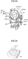
- FIG. 39 is a cut-away side view of another toner container according to the third embodiment of the present invention.
- the reference number of the toner container the same reference number 32Y as that in the first embodiment of the present invention is used.
- a carrying member 320 is formed inside the toner container 32Y.
- the toner container 32Y includes a container main body which is secured to the image forming apparatus main body 100 when the container main body is attached to the image forming apparatus main body 100 (the toner supplying device 60Y) as a relatively large component, and the carrying member 320 formed inside the container main body.
- the carrying member 320 is rotatably supported by two parts of a head part and a tail part of the container main body.
- the carrying member 320 includes plural stirring blades 320a and an engaging member 321 (driven coupling member) which engages with the driving coupling member 90. With this, the carrying member 320 is rotated in a predetermined direction by receiving a driving force from the driving coupling member 90 of the image forming apparatus main body 100, and carries toners in the toner container 32Y in the long length direction (the left direction in FIG. 38 ). Consequently, the toners are discharged from the toner outlet W to the toner tank 61Y.
- the carrying member 320 can be rotatably supported by one part of the tail part of the container main body.
- the shutter member 32Y1a for opening or closing the toner outlet W, the electronic substrate 32Y1c, and so on are formed on the circumferential surface of the toner container 32Y (the container main body).
- the toner container 32Y in order that the toner container 32Y can be operated by being attached to the toner supplying device 60Y, includes the toner outlet W, the shutter member 32Y1a, the guiding member 32Y1g, the contacting section 32Y1h, the pushing member 32Y1k, the electronic substrate 32Y1c, the protrusion member 32Y1d, the protrusion member 32Y1e, the guide rib 32Y1f, the handle part 32Y1d, the elastic member 125, the brim section 32Y1a1, the elastic part 32Y1a2, the stopping part 32Y1a3, the protrusions 32Y1a4, the protrusions 32Ya10, and the slope part 32Y1p.
- the electronic substrate 32Y1c does not contact the flat surface so that the shutter member 32Y1a and the protrusion member 32Y1d become the supporting points contacting the flat surface.
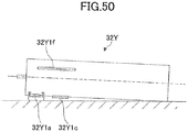
- the shutter member 32Y1a and one end of the toner container 32Y form supporting points and the electronic substrate 32Y1c does not contact the flat surface.
- the electronic substrate 32Y1c is positioned inside a region of a virtual line extending from the shutter member 32Y1a to the one end of the toner container 32Y (the virtual line is the floor surface in FIG. 50 ).
- the protrusion member 32Y1d can be formed.
- the container main body of the toner container 32Y includes the toner outlet W, the shutter member 32Y1a, the guiding member 32Y1g, the contacting section 32Y1h, the pushing member 32Y1k, the electronic substrate 32Y1c, and so on.
- the shutter member 32Y1a When the shutter member 32Y1a is opened (closed) (the toner container 32Y is rotated), the shutter 89 (of the image forming apparatus main body side) of the toner supplying device 60Y is pushed by the container main body (the guiding member 32Y1g and the contacting section 32Y1h), and the toner supplying opening 60Ya is opened (closed).
- the antennas 121Y, 121M, 121C, and 121K for facing the electronic substrates 32Y1c, 32M1c, 32C1c, and 32K1c positioned on the corresponding circumferential surfaces of the toner containers 32Y, 32M, 32C, and 32K arrayed on the supporting part 115 of the image forming apparatus main body 100 are positioned on the antenna substrate 120.
- the image forming apparatus main body 100 (the toner supplying devices 60Y, 60M, 60C, and 60K) is not caused to be great in size in the toner container inserting direction, can be manufactured at low cost with relatively low-cost components, and the assembling efficiency of the image forming apparatus main body 100 can be high.
- the end surface 32Y1g1 of the guiding member 32Y1g pushes the shutter 89 together with the opening operation of the shutter member 32Y1a.
- the toner supplying opening 60Ya of the toner supplying device 60Y is opened, and the toner outlet W of the toner container 32Y is connected to the toner supplying opening 60Ya. Therefore, toners are smoothly supplied to the toner supplying device 60Y from the toner container 32Y. Even if toners are dropped from the toner container 32Y to a part surrounding the toner supplying opening 60Ya, the dropped toners are not visible from a user, and the unsatisfying impression is not given to the user.
- the toner containers 32Y, 32M, 32C, and 32K can contain corresponding two-component developers formed of toners and carrier particles (toner carrier). In this case, the same effects as those in the first through third embodiments of the present invention can be obtained.
- a part or all of the corresponding image forming sections 6Y, 6M, 6C, and 6K can be included in the corresponding process cartridges. In this case, the same effects as those in the first through third embodiments of the present invention can be obtained.
- the toner carrying route formed of the toner tank 61Y, the toner carrying screw 62Y, the toner carrying tube 63Y, and the toner dropping route 64Y of the toner supplying device 60Y is formed in a M-shaped structure viewed from the direction perpendicular to the plane of the paper of FIG. 13 .
- the toner supplying device 60Y is at the left upper position of the image forming section 6Y (process cartridge), and the toner container 32Y is also at the left upper position of the image forming section 6Y. That is, for example, the toner container 32M, and a toner tank and the upstream side of a toner carrying section for magenta are not positioned above the image forming section 6M, but above the image forming section 6Y.
- the present invention is not limited to the specifically disclosed embodiments, and variations and modifications may be made without departing from the scope of the present invention. That is, in the embodiments of the present invention, the number of elements, the positions of the corresponding elements, and the shapes of the corresponding elements are not limited to the specifically disclosed embodiments.
- the present invention is based on Japanese Priority Patent Application No. 2008-231266, filed on September 9, 2008 , Japanese Priority Patent Application No. 2008-234344, filed on September 12, 2008 , Japanese Priority Patent Application No. 2008-248371, filed on September 26, 2008 , and Japanese Priority Patent Application No. 2008-249424, filed on September 29, 2008 , with the Japanese Patent Office, the entire contents of which are hereby incorporated herein by reference.
Landscapes
- Physics & Mathematics (AREA)
- General Physics & Mathematics (AREA)
- Dry Development In Electrophotography (AREA)
Abstract
Description
- The present invention generally relates to a toner container which is attached to an image forming apparatus such as a copying machine, a printer, a facsimile machine, and a multifunctional peripheral having the above functions and an image forming apparatus using the toner container.
- Conventionally, in an image forming apparatus such as a copying machine, a toner container having a cylindrical shape (toner bottle) has been used by being detachably attached to the image forming apparatus (for example, see Patent Document 1).
- In Patent Document 1, a toner container (toner bottle), which is detachably attached to an image forming apparatus main body, is mainly formed of a container main body and a cap section. A spiral protrusion is formed on an inner circumferential surface of the container main body, and when the container main body is rotated, toners contained in the container main body are carried to an opening part of the toner container. The cap section is connected to the container main body and is supported by the image forming apparatus main body without being rotated by the rotation of the container main body. The toners output from the opening part of the container main body are output from a toner output opening of the cap section. The toners output from the toner output opening are supplied to a developing device.
- In addition, a shutter member for opening or closing the toner output opening is formed in the cap section of the toner container. The shutter member opens or closes the toner output opening by being interfaced with attaching or detaching of the toner container to or from the image forming apparatus main body.
- [Patent Document 1] Japanese Unexamined Patent Publication No.
2004-287404 - In a case where the toner container in Patent Document 1 is compared with a toner container without having a cap section, when the toner container in Patent Document 1 is replaced with a new one, stains caused by toners can be decreased. That is, since a toner outlet is opened or closed by interfacing with an attaching or detaching operation of the toner container, a user is prevented from being stained by the toners due to a direct touch of the toner outlet. In addition, since the direction of the toner outlet is a direct downward direction, an amount of toners remaining near the toner outlet may be small as a result of being dropped with the toner's own weight when the toners have been almost consumed (at the toner end time). With this, the stains caused by the toners near the toner outlet can be decreased when the container is replaced with a new one.
- However, a slight amount of toners is adhered onto a part surrounding the toner outlet, and the adhered toners are dropped into the image forming apparatus main body when the toner container is replaced with a new one. In particular, stains caused by the dropped toners have been remarkable at the part surrounding a toner supplying opening of the image forming apparatus main body. Consequently, an unsatisfying impression has been given to the user.
- In order to solve the above problem, it is conceivable that a shutter member is formed to open or close the toner outlet by rotating the toner container in a state where the toner container is attached to the image forming apparatus main body and a main body side shutter is formed to open or close a toner supplying opening of the image forming apparatus main body.
- However, in this case, in order not to generate a toner supplying fault to the image forming apparatus main body, the main body side shutter of the image forming apparatus main body must be surely opened together with an opening operation of the shutter member of the toner container, and the toner outlet of the toner container must be surely connected to the toner supplying opening of the image forming apparatus.
- In a preferred embodiment of the present invention, there is provided a toner container and an image forming apparatus in which a toner supplying fault does not occur from a toner container to an image forming apparatus main body of the image forming apparatus and toners dropped from the toner container to a part surrounding a toner supplying opening of the image forming apparatus main body is hardly visible by a user and the dropped toners do not give an unsatisfying impression to the user when the toner container is replaced with a new one.
- To achieve one or more of these and other advantages, according to one aspect of the present invention, there is provided a toner container having a cylindrical shape which is detachably attached to an image forming apparatus main body of an image forming apparatus. The toner container includes a toner outlet formed at a circumferential surface of the toner container for discharging toners contained in the toner container, a shutter member formed at the circumferential surface of the toner container for opening or closing the toner outlet together with a rotational operation of the toner container in a state where the toner container is attached to the image forming apparatus main body, and a guiding member formed at a part surrounding the toner outlet configured to protrude from the circumferential surface of the toner container for guiding an opening or closing operation of the shutter member in a circumferential direction of the toner container. The image forming apparatus main body includes a toner supplying opening configured to be connected to the toner outlet, and a main body side shutter for opening or closing the toner supplying opening. When the shutter member of the toner container is opened, an end surface of the guiding member pushes the main body side shutter together with the opening operation of the shutter member and the toner outlet is opened, and the toner outlet is connected to the toner supplying opening.
- According to an embodiment of the present invention, when a shutter member opens a toner outlet, an end surface of a guiding member pushes a main body side shutter, and a toner supplying opening is opened. With this, the toner supplying opening is connected to the toner outlet. Therefore, even if toners are adhered onto a surrounding part of the toner supplying opening, the shutter member is surely engaged with the main body side shutter, and the shutter is surely opened by interfacing with the opening operation of the shutter member. With this, an abnormal connection of the toner outlet with the toner supplying opening can be prevented. In addition, since toners dropped from the toner container to a part surrounding the toner supplying opening are hidden by the main body side shutter, stains caused by the dropped toners is hardly visible by a user when the toner container is replaced with a new one. Thus, an unsatisfying impression is not given to the user.
- Features and advantages of the present invention will become more apparent from the following detailed description when read in conjunction with the accompanying drawings, in which:
-
FIG. 1 is a schematic diagram showing a part of a structure of an image forming apparatus main body of an image forming apparatus according to a first embodiment of the present invention; -
FIG. 2 is a schematic diagram showing a part of a structure of the image forming apparatus main body including an image forming section shown inFIG. 1 ; -
FIG. 3 is a perspective view of a part of the structure of the image forming apparatus main body including a toner container storing section shown inFIG. 1 ; -
FIG. 4 is a top view of a part of the structure of the image forming apparatus main body including a toner container storing section shown inFIG. 1 ; -
FIG. 5 is a front view of a part of the structure of the image forming apparatus main body including the toner container storing section shown inFIG. 1 ; -
FIG. 6 is a side view of a part of the structure of the image forming apparatus main body including the toner container storing section shown inFIG. 1 ; -
FIG. 7 is a perspective view of a part of the image forming apparatus main body including the toner container storing section shown inFIG. 1 ; -
FIG. 8 is a front view of a part of the image forming apparatus main body when a main body cover is opened; -
FIG. 9 is a front view of inserting openings into which the corresponding toner supplying devices shown inFIG. 1 are inserted; -
FIG. 10 is a perspective view of the toner container storing section shown inFIG. 1 ; -
FIG. 11A is a plan view of the toner supplying devices shown inFIG. 1 to which the corresponding toner containers are attached; -
FIG. 11B is a front view of the toner supplying devices shown inFIG. 1 to which the corresponding toner containers are attached; -
FIG. 12 is a schematic diagram showing a state where the toner container is connected to the toner supplying device; -
FIG. 13 is a cut-away side view of the toner supplying device; -
FIG. 14 is an external side view of the toner supplying device; -
FIG. 15 is a perspective view of the toner supplying device; -
FIG. 16 is a perspective view of the toner supplying device when the toner supplying opening is opened; -
FIG. 17 is another perspective view of the toner supplying device when the toner supplying opening is opened; -
FIG. 18 is a perspective view of the toner supplying device when a shutter is attached to a position of the toner supplying opening; -
FIG. 19 is a perspective view of the toner container; -
FIG. 20 is another perspective view of the toner container; -
FIG. 21 is a diagram showing the toner container; -
FIG. 22 is a perspective view of a head part of the toner container when a shutter member is opened; -
FIG. 23 is a perspective view of a cap section of the toner container; -
FIG. 24 is a cut-away side view of the head part of the toner container; -
FIG. 25 is a perspective view of a cap section main body of the toner container for yellow; -
FIG. 26 is a perspective view of a cap section main body of the toner container for magenta; -
FIG. 27 is a perspective view of a cap section main body of the toner container for cyan; -
FIG. 28 is a perspective view of a cap section main body of the toner container for black; -
FIG. 29 is a diagram showing a handle main body of the toner container; -
FIG. 30 is a perspective view of the handle main body of the toner container; -
FIG. 31 is a perspective view of a part of the toner container; -
FIG. 32 is a schematic diagram showing the head part of the toner container attached to the toner supplying device; -
FIG. 33 is perspective view when the toner container is attached to the toner supplying device; -
FIG. 34 is a schematic diagram when the toner container is attached to the toner supplying device; -
FIG. 35 is a perspective view of an elastic member; -
FIG. 36 is a perspective view of a toner container according to a second embodiment of the present invention; -
FIG. 37 is a cut-away side view of a head part of the toner container shown inFIG. 36 ; -
FIG. 38 is a cut-away side view of a toner container according to a third embodiment of the present invention; -
FIG. 39 is a cut-away side view of another toner container according to the third embodiment of the present invention; -
FIG. 40 is a perspective view of the head part of the toner container; -
FIG. 41 is a cut-away side view of the head part of the toner container; -
FIG. 42 is a cross-sectional view of the toner container along line X-X ofFIG. 41 ; -
FIG. 43 is a front view of the toner supplying device to which the toner container has been attached; -
FIG. 44 is a perspective view of the toner supplying device to which the toner container has been attached; -
FIG. 45 is a diagram showing a part of the toner supplying device shown inFIG. 43 ; -
FIG. 46 is a diagram showing rolling states of the toner container; -
FIG. 47 is a perspective view of the toner supplying device when a brim section is not formed in the shutter member; -
FIG. 48 is another cut-away side view of the head part of the toner container; -
FIG. 49 is a perspective view of the head part of the toner container according to the third embodiment of the present invention; and -
FIG. 50 is a diagram showing the toner container in a state where the toner contaner is put on a flat surface. - Referring to the drawings, embodiments of the present invention are described in detail.
- Referring to
FIGs. 1 through 35 , a first embodiment of the present invention is described in detail. - First, a structure and operations of an image forming apparatus are described.
-
FIG. 1 is a schematic diagram showing a part of a structure of an image forming apparatusmain body 100 of an image forming apparatus according to the first embodiment of the present invention. - As shown in
FIG. 1 , in a tonercontainer storing section 31 at an upper part of the image forming apparatusmain body 100, fourtoner containers container storing section 31. - An
intermediate transfer unit 15 is provided under the tonercontainer storing section 31. Theintermediate transfer unit 15 includes anintermediate transfer belt 8.Image forming sections intermediate transfer belt 8. -
Toner supplying devices toner containers toner containers image forming sections toner supplying devices - Some elements in
FIG. 1 which are not described above are described below. - In the following, since elements for processing the corresponding colors yellow, magenta, cyan and black are substantially identical to each other, in some cases, elements for the yellow color having suffix Y are described as representative.
-
FIG. 2 is a schematic diagram showing a part of a structure of the image forming apparatusmain body 100 including theimage forming section 6Y shown inFIG. 1 . - As shown in
FIG. 2 , theimage forming section 6Y corresponding to the yellow color includes aphotoconductor drum 1Y, acharging section 4Y facing thephotoconductor drum 1Y, a developingdevice 5Y (developing section), acleaning section 2Y, and a discharging section (not shown). Image forming processes (a charging process, an exposing process, a developing process, a transferring process, and a cleaning process) are performed on thephotoconductor drum 1Y, and a yellow image is formed on thephotoconductor drum 1Y. - Each of the
image forming sections image forming section 6Y and forms a corresponding color image. Therefore, in the following, theimage forming section 6Y is mainly described while omitting the descriptions of theimage forming sections - In
FIG. 2 , thephotoconductor drum 1Y is rotated clockwise by a driving motor (not shown). Then, the surface of thephotoconductor drum 1Y is uniformly charged by the chargingsection 4Y (the charging process). - The surface of the
photoconductor drum 1Y reaches a position where laser beams L are radiated from an exposing device 7 (seeFIG. 1 ) and an electrostatic latent image corresponding to yellow is formed at the position by being exposed by the laser beams (the exposing process). - Then the surface of the
photoconductor drum 1Y on which the electrostatic latent image has been formed reaches a position facing the developingdevice 5Y, the electrostatic latent image is developed at the position, and a yellow toner image is formed (the developing process). - Then the surface of the
photoconductor drum 1Y on which the toner image has been formed reaches a position facing theintermediate transfer belt 8 and a primarytransfer bias roller 9Y, and the toner image on thephotoconductor drum 1Y is transferred onto theintermediate transfer belt 8 at the position (a primary transferring process). At this time, a small amount of toners which have not been transferred onto theintermediate transfer belt 8 remain on thephotoconductor drum 1Y. - Then the surface of the
photoconductor drum 1Y reaches a position facing thecleaning section 2Y and the toners remaining on the surface of thephotoconductor drum 1Y are mechanically removed by acleaning blade 2a (the cleaning process). - Finally, the surface of the
photoconductor drum 1Y reaches a position facing the discharging section and electric charges remaining on the surface of thephotoconductor drum 1Y are discharged. - By the above processes, the image forming process on the
photoconductor drum 1Y is completed. - The above image forming process is performed in the
image forming sections image forming section 6Y. That is, the laser beams L corresponding to image information are radiated onto the corresponding photoconductor drums 1M, 1C, and 1K from the exposingdevice 7 positioned under theimage forming sections device 7 causes a light source to emit the laser beams L and radiates the laser beams L onto the corresponding photoconductor drums 1M, 1C, and 1K via plural optical elements while the laser beams L are scanned by a rotating polygon mirror. - After the developing process, the toner images formed on the corresponding
photoconductor drums intermediate transfer belt 8 by being superposed. With this, a color image is formed on theintermediate transfer belt 8. - Returning to
FIG. 1 , theintermediate transfer unit 15 includes theintermediate transfer belt 8, four primarytransfer bias rollers transfer backup roller 12, plural tension rollers (not shown), and an intermediate transfer cleaning section (not shown). Theintermediate transfer belt 8 is supported by plural rollers and is endlessly rotated in the arrow direction by the secondarytransfer backup roller 12. - Primary transfer nips are formed by sandwiching the
intermediate transfer belt 8 between the four primarytransfer bias rollers photoconductor drums transfer bias rollers - The
intermediate transfer belt 8 sequentially passes through the primary transfer nips of the primarytransfer bias rollers photoconductor drums intermediate transfer belt 8 by being superposed. - The
intermediate transfer belt 8 onto which the toner images have been transferred by being superposed reaches a position facing asecondary transfer roller 19. A secondary transfer nip is formed at the position where theintermediate transfer belt 8 is sandwiched between the secondarytransfer backup roller 12 and thesecondary transfer roller 19. Then, the four-color toner image formed on theintermediate transfer belt 8 is transferred onto a recording medium P (for example, paper) carried to the position of the secondary nip (a secondary transferring process). At this time, toners which have not been transferred onto the recording medium P remain on theintermediate transfer belt 8. - Then the
intermediate transfer belt 8 reaches a position facing the intermediate transfer cleaning section and the toners remaining on theintermediate transfer belt 8 are removed at the position. - With this, the transfer process which is performed on the
intermediate transfer belt 8 is completed. - The recording medium P is carried to the position of the secondary nip from a
paper feeding section 26 at a lower part of the image forming apparatusmain body 100 via apaper feeding roller 27, a pair ofregistration rollers 28, and so on. - Specifically, the plural recording media P (many pieces of paper) are stored in the
paper feeding section 26 by being stacked. When thepaper feeding roller 27 is rotated counterclockwise, a top recording medium P is carried to a position between the pair ofregistration rollers 28. - The recording medium P carried to the pair of
registration rollers 28 is temporarily stopped at a roller nip position of the pair ofregistration rollers 28 whose rotation is stopped. Then the pair ofregistration rollers 28 is rotated again by matching the timing of the color image on theintermediate transfer belt 8, and the recording medium P is carried to the secondary transfer nip. With this, the color image is transferred onto the recording medium P. - The recording medium P onto which the color image has been transferred at the position of the secondary transfer nip is carried to a fixing
section 20 and the color image on the recording medium P is fixed by heat and pressure from a corresponding fixing belt and a pressure applying roller of the fixingsection 20. - The recording medium P on which the color image has been formed is output to a stacking
section 30 via a pair ofpaper outputting rollers 29. When plural recording media P are output, the output plural recording media P are sequentially stacked on the stackingsection 30. - By the above processes, the image forming process in the image forming apparatus
main body 100 is completed. - Next, returning to
FIG. 2 , a structure and operations of the developingdevice 5Y in theimage forming section 6Y are described in detail. - The developing
device 5Y includes a developingroller 51Y facing thephotoconductor drum 1Y, adoctor blade 52Y facing the developingroller 51Y,developer containers screws 55Y in the correspondingdeveloper containers concentration detecting sensor 56Y for detecting a toner concentration in a developer G. - The developing
roller 51Y includes a magnet (not shown) secured inside the developingroller 51Y and a sleeve (not shown) which is rotated around the magnet. The developer G (two-component developer) formed of carrier particles (toner carrier) and toners is contained in thedeveloper containers developer container 54Y is connected to atoner dropping route 64Y via an opening formed at an upper side of thedeveloper container 54Y. - Next, operations of the developing
device 5Y are described. - The sleeve of the developing
roller 51Y is rotated in the arrow direction shown inFIG. 2 . The developer G carried on the developingroller 51Y by a magnetic field generated by the magnet is moved on the developingroller 51Y while the sleeve is rotated. - The toner concentration of the developer G in the developing
device 5Y is adjusted to be a value within a predetermined range. Specifically, toners contained in thetoner container 32Y (seeFIG. 1 ) are supplied to thedeveloper container 54Y via thetoner supplying device 60Y (seeFIG. 1 ) corresponding to a consumed amount of toners in the developingdevice 5Y. Thetoner supplying device 60Y is described below in detail. - The toners supplied to the
developer container 54Y are mixed with the developer G in thedeveloper container 54Y, and the developer G is circulated in the twodeveloper containers screws 55Y. The developer G is moved in the direction perpendicular to the plane of the paper ofFIG. 2 . - The toners in the developer G are adhered to carrier particles by a friction charge with the carrier particles and are carried on the developing
roller 51Y with the carrier particles by a magnetic force formed on the developingroller 51Y. - The developer G carried on the developing
roller 51Y reaches thedoctor blade 52Y by being carried in the arrow direction. The amount of the developer G on the developingroller 51Y is adjusted to be a suitable value by thedoctor blade 52Y and the developer G whose amount is adjusted is carried to a position facing thephotoconductor drum 1Y. The position is a developing region. The toners in the developer G are adhered onto an electrostatic latent image formed on thephotoconductor drum 1Y by an electric field generated in the developing region. The developer G remaining on the developingroller 51Y reaches an upper part in thedeveloper container 53Y by the rotation of the sleeve and the remaining developer G is dropped from the developing roller 51Y._ - Next, referring to
FIGs. 3 through 18 , thetoner supplying devices -
FIG. 3 is a perspective view of a part of the structure of the image forming apparatusmain body 100 including the tonercontainer storing section 31 shown inFIG. 1 .FIG. 4 is a top view of a part of the structure of the image forming apparatusmain body 100 including the tonercontainer storing section 31 shown inFIG. 1 .FIG. 5 is a front view of a part of the structure of the image forming apparatusmain body 100 including the tonercontainer storing section 31 shown inFIG. 1 . - In
FIGs. 3 through 5 , the toners contained in the correspondingtoner containers container storing section 31 are suitably supplied to the corresponding developing devices by the correspondingtoner supplying devices - The structure of each of the
toner supplying devices toner containers toner supplying device 60Y and thetoner container 32Y are described as representative. - In
FIGs. 3 through 5 , when thetoner container 32Y is installed in the tonercontainer storing section 31, a shutter member of thetoner container 32Y is moved in synchronization with the installation of thetoner container 32Y, and a toner outlet W (seeFIG. 12 ) of thetoner container 32Y is opened. In addition, a shutter 89 (main body side shutter) (seeFIG. 18 ) of the image forming apparatusmain body 100 is moved and a toner supplying opening 60Ya (seeFIG. 18 ) of thetoner supplying device 60Y is opened. Consequently, the toner outlet W is connected to the toner supplying opening 60Ya. - With this, the toners contained in the
toner container 32Y are discharged from the toner outlet W and are stored in a toner tank of thetoner supplying device 60Y. -
FIG. 12 is a schematic diagram showing a state where thetoner container 32Y is connected to the toner supplying device 60. - In
FIG. 12 , thetoner container 32Y is an approximately cylinder-shaped toner bottle, and includes a spiral protrusion on the internal circumferential surface of thetoner container 32Y. When the spiral protrusion is viewed from the outside, a spiral groove is viewed. When thetoner container 32Y is rotated in the arrow direction by a drivingsection 71, the spiral protrusion discharges the toners from the toner outlet W. The drivingsection 71 includes a drivingmotor 80, a drivingcoupling member 90, and a gear 91 (seeFIG. 6 ). - That is, when the
toner container 32Y is suitably rotated by the drivingsection 71, the toners are suitably supplied to atoner tank 61Y of the toner supplying device 60. When the service life of each of thetoner containers toner container 32Y have been consumed, an old one is replaced with a new one. - In
FIG. 12 , thetoner supplying device 60Y includes thetoner tank 61Y, atoner carrying screw 62Y, atoner carrying tube 63Y (seeFIG. 13 ), atoner dropping route 64Y (seeFIG. 13 ), atoner stirring member 65Y, and atoner end sensor 66Y (detecting unit). Thetoner carrying screw 62Y and thetoner carrying tube 63Y form a toner carrying section (seeFIG. 13 ). -
FIG. 6 is a side view of a part of the structure of the image forming apparatusmain body 100 including the tonercontainer storing section 31 shown inFIG. 1 . - In
FIG. 6 , the driving section 71 (seeFIG. 12 ) includes the drivingmotor 80, the drivingcoupling member 90, and a gear train formed ofgears 81 through 84 (seeFIG. 14 ), 91, and 92, a drivingforce transmitting shaft 81a, a droppingpart shutter 86, a supporting member (not shown), an antenna substrate 120 (seeFIG. 10 ), a toner receiving section 85 (seeFIG. 3 ), and the shutter 89 (seeFIG. 18 ). - In
FIGs. 3 through 6 , the drivingcoupling member 90 for engaging with an engaging section 32Y2b (seeFIG. 20 ) formed at the bottom of thetoner container 32Y is positioned at the back side of thetoner supplying device 60Y (at the back side of the toner container attaching direction). A driving force of the drivingmotor 80 is transmitted to the drivingcoupling member 90 via the gear 91 (double gear), and a container main body 32Y2 of thetoner container 32Y is rotated in a predetermined direction by the drivingcoupling member 90. - The
gear 92 which engages with thegear 91 transmits the driving force to thegear 81 positioned at the front side of thetoner supplying device 60Y via the drivingforce transmitting shaft 81a. The driving force transmitted to thegear 81 rotates thetoner carrying screw 62Y and thetoner stirring member 65Y via the gear train formed of thegears 81 through 84. The structure of thetoner supplying device 60Y at the front side where thetoner carrying screw 62Y and thetoner stirring member 65Y are positioned is described below in detail by referring toFIGs. 12 through 18 . -
FIG. 7 is a perspective view of a part of the image forming apparatusmain body 100 including the tonercontainer storing section 31. - As shown in
FIG. 7 , when a main body cover (not shown) positioned at the front side of the image forming apparatusmain body 100 is opened, the tonercontainer storing section 31 is exposed.FIG. 8 is a front view of a part of the image forming apparatusmain body 100 when the main body cover is opened. As shown inFIG. 8 , when the main body cover is opened, aninner cover 109 is exposed in which four insertingopenings toner containers openings toner containers main body 100 in the long length direction of thetoner containers -
FIG. 9 is a front view of inserting openings into which the correspondingtoner supplying devices FIG. 8 , the shapes of the insertingopenings FIG. 9 , the shapes of insertingopenings toner supplying devices - Specifically, as shown in
FIG. 9 , in each of the insertingopenings first guide groove 111; into which corresponding guide ribs 32Y1f, 32M1f, 32C1f, and 32K1f (seeFIGs. 25 through 28 ) formed at corresponding cap sections of thetoner containers - In addition, in the inserting
openings second guide grooves FIGs. 25 through 28 ) formed at the corresponding cap sections of thetoner containers second guide grooves toner supplying devices - The
second guide grooves FIG. 9 , at the right sides) in the corresponding insertingopenings first guide grove 111 is determined to be a reference. That is, the protrusion members 32Y1d and 32Y1e, 32M1d and 32M1e, 32C1d and 32C1e, and 32K1d and 32K1e which are different from each other are positioned near the corresponding guide ribs 32Y1f, 32M1f, 32C1f, and 32K1f. - Since the
second guide grooves openings FIG. 9 ; the distance between the adjacent two of the insertingopenings - In
FIG. 9 , in each of the insertingopenings toner supplying devices part 113 having a groove shape is formed. As a representative, a stopping part 32Y1a3 of a shutter member 32Y1a (seeFIGs. 40 ,42, and 43 ) of thetoner container 32Y is engaged into the stoppedpart 113. - With this, when the
toner container 32Y is attached to or detached from the image forming apparatusmain body 100, the movement of thetoner container 32Y in the short length direction (the lateral direction of the paper ofFIG. 9 ) of thetoner container 32Y can be prevented. In particular, when a user rotates a cap section 32Y1 by grasping a handle part 32Y1b (seeFIGs. 40 and43 ) in a state where thetoner container 32Y has been attached to the image forming apparatusmain body 100, even if the a rotational force of the user is biased to one side, since the stopping part 32Y1a3 of thetoner container 32Y has been engaged into the stoppedpart 113 of thetoner supplying device 60Y, thetoner container 32Y can be normally attached to thetoner supplying device 60Y. -
FIG. 10 is a perspective view of the tonercontainer storing section 31.FIG. 11A is a plan view of thetoner supplying devices toner containers FIG. 11B is a front view of thetoner supplying devices toner containers - In the first embodiment of the present invention, the
toner containers toner supplying devices FIG. 10 , theantenna substrate 120 is positioned on a supportingpart 115 of the tonercontainer storing section 31. - Specifically, four
antennas antenna substrate 120. The fourantennas FIGs. 25 through 28 ) positioned on the circumferential surfaces of the correspondingtoner containers antenna substrate 120 is under thetoner containers part 115 of the tonercontainer storing section 31. - Information is transmitted and received between the electronic substrates 32Y1c, 32M1c, 32C1c, and 32K1c of the
toner containers antennas antenna substrate 120 positioned in the image formingmain body 100. The information to be communicated with each other is, for example, the production serial number of the toner container, the recycled number of the toner container, the kind of toners, the production lot number of toners, the production date of toners, the manufacturer of toners, the amount of toners in the toner container, the color of toners, and a usage history of the image forming apparatusmain body 100. - In the first embodiment of the present invention, since the electronic substrates 32Y1c, 32M1c, 32C1c, and 32K1c face the corresponding
antennas antennas antennas part 115 of thetoner storing section 31, thetoner supplying device main body 100 and manufacturing cost of the image forming apparatusmain body 100 can be relatively low, and the installing capability of the image forming apparatusmain body 100 in an office can be increased. -
FIG. 32 is a schematic diagram showing a head part of thetoner container 32Y attached to thetoner supplying device 60Y. As shown inFIG. 32 , the antenna substrate 120 (theantenna 121Y) is positioned at the right side of the toner outlet W of thetoner container 32Y. Even if toners are leaked from the toner outlet W, the toners are dropped to the left side of the image forming apparatusmain body 100. - Specifically, when the engaging section 32Y2b (see
FIG. 20 ) of the container main body 32Y2 is at a position where the engaging section 32Y2b engages with the driving coupling member 90 (seeFIG. 6 ), the toner outlet W is separated from theantenna substrate 120 and the electronic substrate 32Y1c facing theantenna substrate 120 by the insertingopening 110Y (seeFIG. 9 ). Therefore, the toners are hardly dropped on theantenna substrate 120 directly. Consequently, the decrease of the communication sensitivity due to the drop of the toners at a position between the electronic substrate 32Y1c and theantenna 121Y can be prevented. - Since it is preferable that the electronic substrate 32Y1c of the
toner container 32Y is positioned to face theantenna substrate 120, the electronic substrate 32Y1c is positioned at the back side relative to the position of the toner outlet W. - That is, the electronic substrate 32Y1c is positioned at the back side of the toner supplying opening 60Ya of the image forming apparatus
main body 100. Therefore, when thetoner container 32Y is attached to or detached from thetoner supplying device 60Y, the electronic substrate 32Y1c passes through an adjacent position over the toner supplying opening 60Ya. Consequently, there is a risk that the electronic substrate 32Y1c is contaminated by a small amount of a powder smoke of the toners. In order to solve the above problem, the shutter 89 (the main body side shutter) closes the toner supplying opening 60Ya. - Referring to
FIGs. 12 through 18 , a structure and operations of thetoner supplying device 60Y are described in detail. -
FIG. 13 is a cut-away side view of thetoner supplying device 60Y.FIG. 14 is an external side view of thetoner supplying device 60Y.FIG. 15 is a perspective view of thetoner supplying device 60Y.FIG. 16 is a perspective view of thetoner supplying device 60Y when the toner supplying opening 60Ya is opened.FIG. 17 is another perspective view of thetoner supplying device 60Y when the toner supplying opening 60Ya is opened.FIG. 18 is a perspective view of thetoner supplying device 60Y when theshutter 89 is attached to a position of the toner supplying opening 60Ya. - In
FIGs. 12 through 18 , thetoner supplying device 60Y includes thetoner tank 61Y, thetoner carrying screw 62Y, thetoner carrying tube 63Y, thetoner dropping route 64Y, thetoner stirring member 65Y, thetoner end sensor 66Y (detecting unit), the gear train formed of thegears 81 through 84, thetoner receiving section 85, the shutter 89 (main body side shutter). Theshutter 89 is only shown inFIGs. 18 and34 , and is omitted in the other drawings. - The
toner tank 61Y is under the toner outlet W of the cap section 32Y1 of thetoner container 32Y and stores the toners discharged from the toner outlet W of thetoner container 32Y via the toner supplying opening 60Ya. The bottom part of thetoner tank 61Y is connected to an upstream side of a toner carrying section (thetoner carrying screw 62Y and thetoner carrying tube 63Y). - The
toner end sensor 66Y is on a wall surface of thetoner tank 61Y at a position having a predetermined height from the bottom surface of thetoner tank 61Y. Thetoner end sensor 66Y detects a signal when the amount of the toners stored in thetoner tank 61Y becomes a value less than a predetermined value. As thetoner end sensor 66Y, a piezoelectric sensor can be used. - In
FIG. 12 , when thetoner end sensor 66Y detects a signal that the amount of the toners stored in thetoner tank 61Y has become a value less than a predetermined value, the signal is sent to a controllingsection 70. The controllingsection 70 controls the driving section 71 (the drivingmotor 80, the drivingcoupling member 90, and the gear 91 (seeFIG. 6 )) to rotate thetoner container 32Y for a predetermined period so as to supply toners to thetoner tank 61Y. When thetoner end sensor 66Y continues to detect the signal even if the drivingsection 71 repeats rotating thetoner tank 32Y, the controllingsection 70 determines that no toners remain in thetoner container 32Y. Then the controllingsection 70 displays a message which instructs to replace the existingtoner container 32Y with a new one on a displaying section (not shown) of the image forming apparatusmain body 100. - The
toner stirring member 65Y (rotating member) is at an inner center position of thetoner tank 61Y near thetoner end sensor 66Y for preventing the toners stored in thetoner tank 61Y from being condensed. Thetoner stirring member 65Y includes a flexible member 65Ya, and rotates in the arrow direction clockwise as shown inFIG. 12 , and stirs the toners in thetoner tank 61Y. In addition, since the tip of the flexible member 65Ya of thetoner stirring member 65Y slidably contacts the detecting surface of thetoner end sensor 66Y with a rotational cycle of thetoner stirring member 65Y, a decrease in the detecting accuracy due to adhering toners onto the detecting surface of thetoner end sensor 66Y is prevented. - As shown in
FIGs. 14 and15 , the gear 82 (a bevel gear) having a twisting angle of 45 degrees is attached to one end of the shaft of thetoner stirring member 65Y, and a driving force is transmitted to thetoner stirring member 65Y via the gear 81 (a bevel gear) having a twisting angle of 45 degrees engaged with thebevel gear 82. - In
FIG. 13 , thetoner carrying screw 62Y and thetoner carrying tube 63Y carry the toners stored in thetoner tank 61Y in the obliquely upward direction (the arrow direction). Specifically, thetoner carrying screw 62Y and thetoner carrying tube 63Y linearly carry the toners from the bottom part (the lowest part) of thetoner tank 61Y to a position above the developingdevice 5Y (a toner dropping opening 64Ya of thetoner dropping route 64Y). The toners reaching the toner dropping opening 64Ya are supplied to thedeveloper container 54Y (seeFIG. 2 ) of the developing device 5 by the toner's own weight via thetoner dropping route 64Y. - The
toner carrying screw 62Y carries the toners by being rotated in a predetermined direction, and thetoner carrying tube 63Y has an inner wall adjacent to thetoner carrying screw 62Y. As described above, the toner carrying section includes thetoner carrying screw 62Y and thetoner carrying tube 63Y. - The
toner carrying screw 62Y is a screw member in which a helicoid is spirally formed on a shaft and is rotatably supported in thetoner carrying tube 63Y via bearings (not shown). As shown inFIGs. 14 and15 , the gear (skew gear) 84 is attached to one end of thetoner carrying screw 62Y, and a driving force is transmitted to thetoner carrying screw 62Y via the gear 83 (skew gear) attached to the shaft of thetoner stirring member 65Y in which thegear 83 is engaged with thegear 84. - The upstream side of the
toner carrying tube 63Y is connected to thetoner tank 61Y and the downstream side of thetoner carrying tube 63Y is connected to thetoner dropping route 64Y via the toner dropping opening 64Ya (seeFIG. 13 ). Thetoner carrying tube 63Y is a tube-shaped member formed of a resin material. Thetoner carrying screw 62Y (screw member) is rotatably supported in thetoner carrying tube 63Y via a bearing. The gap between the external diameter of thetoner carrying screw 62Y and the inner wall of thetoner carrying tube 63Y is determined to be approximately 0.1 to 0.2 mm. With this, the toners are smoothly carried in the obliquely upward direction against the gravitational force by thetoner carrying screw 62Y and thetoner carrying tube 63Y. - As described above, in the first embodiment of the present invention, the toners stored in the
toner tank 61Y are carried in the obliquely upward direction by thetoner carrying screw 62Y and thetoner carrying tube 63Y, and the carried toners are supplied to the developingdevice 5Y by the toner's own weight via thetoner dropping route 64Y. With this, even if the rotation of thetoner carrying screw 62Y is stopped when the supply of the toners to the developingdevice 5Y is stopped, the toners remaining in thetoner carrying tube 63Y are hardly dropped into the developingdevice 5Y via thetoner dropping route 64Y. - Specifically, the toners remaining at a position separated from the toner dropping opening 64Ya slide toward the
toner tank 61Y along the obliquetoner carrying tube 63Y or stay at the position. In addition, the toners remaining at a position near the toner dropping opening 64Ya in thetoner carrying tube 63Y are not greatly dropped from the toner dropping opening 64Ya by the toner's own weight even if the apparatus is subjected to a great shock, and the toners slide toward thetoner tank 61Y along the obliquetoner carrying tube 63Y or stay at the position. - Therefore, even if the rotation and non-rotation of the
toner carrying screw 62Y are repeated, the amount of toners to be supplied to the developingdevice 5Y can be controlled at high accuracy; that is, the toners can be stably supplied to the developingdevice 5Y. Consequently, the variation of the toner concentration in the developer G can be prevented. That is, the image density of an output image can be prevented from being high, the toners can be prevented from being scattered, and the background image can be prevented from being degraded. - In addition, even if the rotation and non-rotation of the
toner carrying screw 62Y are repeated, a large amount of toners remaining in thetoner carrying tube 63Y are not supplied to the developingdevice 5Y. Therefore, the amount of toners remaining in thetoner tank 61Y is not greatly varied. Consequently, error detection by thetoner end sensor 66Y can be prevented. - In
FIG. 13 , in order to surely obtain the above effect, it is preferable that the inclination angle α of thetoner carrying screw 62Y and thetoner carrying tube 63Y relative to the horizontal direction be 5 or more degrees (α ≥ 5 °). However, when the inclination angle α becomes too large, the toner carrying ability by thetoner carrying screw 62Y and thetoner carrying tube 63Y is lowered and the height of the apparatus becomes great. Therefore, in the first embodiment of the present invention, the inclination angle α is determined to be approximately 10 degrees. - In addition, as shown in
FIGs. 14 ,15 and17 , the droppingpart shutter 86 is attached to thetoner dropping route 64Y, and the droppingpart shutter 86 is opened or closed when the developingdevice 5Y is attached to or detached from the image forming apparatusmain body 100. Specifically, when the developingdevice 5Y is attached to the image forming apparatusmain body 100, the droppingpart shutter 86 moves to open thetoner dropping route 64Y by being pushed by the developingdevice 5Y against a force of aspring 87. When the developingdevice 5Y is detached from the image forming apparatusmain body 100, the droppingpart shutter 86 moves to close thetoner dropping route 64Y by the force of thespring 87. With this, when the developingdevice 5Y is detached from the image forming apparatusmain body 100, the toners cannot be scattered in the image forming apparatusmain body 100 from thetoner dropping route 64Y. - As shown in
FIGs. 16 and 17 , a seal member formed of ahair implantation seal 67Y, a sponge seal 68Y2, a sheet-shaped member 68Y3, and so on is adhered onto a part surrounding the toner supplying opening 60Ya of thetoner tank 61Y. The sponge seal 68Y2 contacts a flange W2 of the toner outlet W (seeFIG. 23 ) of thetoner container 32Y and obtains the sealing capability between thetoner tank 32Y and thetoner tank 61Y. The sheet-shaped member 68Y3 is formed of a low friction material, contacts the shutter member 32Y1a (seeFIG. 23 ) which is opened, and prevents the toners from being stayed between the shutter member 32Y1a and thetoner tank 61Y. Thehair implantation seal 67Y scrapes the toners adhered onto the surface of the shutter member 32Y1a with the detaching operation of thetoner container 32Y from the image forming apparatusmain body 100. The toners scraped by thehair implantation seal 67Y are dropped into thetoner receiving section 85 via anopening 85a where a round surface 60Yc is formed. - Supply opening guides 69Y are at positions which sandwich the toner supplying opening 60Ya of the
toner tank 61Y. The supply opening guides 69Y guide the flange W2 of the toner outlet W (seeFIG. 23 ) and prevent the toner outlet W from being moved in the upward direction from the toner supplying opening 60Ya. - As shown in
FIGs. 18 and34 , the shutter 89 (main body side shutter), which opens or closes the toner supplying opening 60Ya connecting to the toner outlet W of thetoner container 32Y (seeFIG. 23 ), is positioned in thetoner supplying device 60Y (the image forming apparatus main body 100). Theshutter 89 is formed to have a curve so that theshutter 89 fits the circumferential surface of thetoner container 32Y (the cap section 32Y1). - In addition, the
toner supplying device 60Y includes a sliding surface (not shown) on which theshutter 89 slides in the circumferential direction of thetoner supplying device 60Y. In order to fill a gap between the sliding surface and theshutter 89, a sealing member can be adhered onto the sliding surface. - The
shutter 89 opens or closes the toner supplying opening 60Ya by being pushed by the cap section 32Y1 (a guiding member 32Y1g and a contacting section 32Y1h) together with an opening or closing operation of the shutter member 32Y1a. With this, the toner outlet W of thetoner container 32Y is connected to the toner supplying opening 60Ya of thetoner supplying device 60Y. The above elements are described below in detail. - As described above, the antenna substrate 120 (see
FIG. 10 ) is positioned at the back side in the attaching direction (the right side ofFIG. 32 ) of thetoner containers part 115 of the tonercontainer storing section 31. Therefore, toners are hardly dropped on the antenna 121 directly. - In the first embodiment of the present invention, since the
antenna 121Y communicates with the electronic substrate 32Y1c without contact, the powder smoke of the toners are prevented from being dropped on theantenna 121Y as described below. - As shown in
FIG. 44 , in the toner supplying device 60, at a position between theantenna 121Y and the electronic substrate 32Y1c when thetoner container 32Y is attached to thetoner supplying device 60Y, a brim section 31Ya is positioned to cover theantenna 121Y. That is, when thetoner container 32Y is attached to thetoner supplying device 60Y in the dotted-line arrow direction, the brim section 31Ya is positioned between theantenna 121Y and the electronic substrate 32Y1c, and communications are performed between theantenna 121Y and the electronic substrate 32Y1c. - Brim sections (not shown) are positioned between the
antenna substrate 120 and the correspondingantennas - Therefore, even if the attaching and detaching operations of the
toner container 32Y to and from thetoner supplying device 60Y are repeated, toners adhered onto thetoner container 32Y can be prevented from being dropped on theantenna 121Y. Consequently, a communication failure between theantenna 121Y and the electronic substrate 32Y1c can be prevented. - As shown in
FIG. 45 , a partition section 31Yb is positioned between the toner supplying opening 60Ya to be connected to the toner outlet W of thetoner container 32Y (the cap section 32Y1) and the brim section 31Ya. The partition section 31Yb is a wall member whose height is greater than the heights of the toner supplying opening 60Ya and the brim section 31Ya in the vertical direction. Therefore, the toners are prevented from flowing from the toner supplying opening 60Ya to the brim section 31Ya. - In addition, as shown in
FIG. 44 , the brim section 31Ya is formed to be a curved surface so that the circumferential surface of thetoner container 32Y (the cap section 32Y1) fits the curved surface. That is, wall sections 31Ya1 are formed to cover the circumferential surface of thetoner container 32Y (the cap section 32Y1) at both ends of the brim section 32Ya in the short length direction of the brim section 31Ya. InFIG. 44 , one of the wall sections 31Ya1 is shown. With this, toners are prevented from flying to an adjacent antenna. Specifically, when the wall sections 31Ya1 are formed to the brim section 31Ya, theantenna 121M adjacent to theantenna 121Y is prevented from being contaminated by flying of the toners from thetoner container 32Y. - In addition, since the brim section 31Ya is formed to be the curved surface, the
toner container 32Y can be smoothly attached to or detached from thetoner supplying device 60Y by being guided with the brim section 31Ya. With this, vibrations of thetoner containers 32Y at the attaching or detaching operation of thetoner container 32Y can be decreased, and toners adhered onto thetoner container 32Y can be prevented from being flown and dropped. - The inventors of the present embodiment have performed an experiment. In the experiment, the
toner container 32Y containing 200 g of toners was attached to and detached from thetoner supplying 30 times, and an amount of toners dropped and adhered onto thedevice 60Yantenna 121Y was measured. The toners adhered onto theantenna 121Y were collected on a transparent tape, and the toners on the transparent tape were optically measured by using an ID measuring instrument X-Rite. When the ID value measured by the ID measuring instrument is great, the amount of adhered toners is great. - In the results of the experiment, when the brim section 31Ya was not the curved surface, the ID value was 0.09, when the brim section 31Ya was not the curved surface and the partition section 31Yb was formed, the ID value was 0.04, and when the brim section 31Ya was the curved surface and the partition section 31Yb was not formed, the ID value was 0.06. Further, when the brim section 31Ya was not formed, the ID value was 0.98. Therefore, when the brim section 31Ya was formed, an excellent effect was obtained.
- Next, referring to
FIGs. 19 through 35 , thetoner container 32Y is described in detail. - As shown in
FIGs. 19 through 21 , thetoner container 32Y is a cylindrical container, and includes the cap section 32Y1 and the container main body 32Y2. - The container main body 32Y2 includes an opening section and the opening section is connected to the inside of the cap section 32Y1. A spiral protrusion 32Y2a is formed on the inner wall of the container main body 32Y2. The container main body 32Y2 is rotated in a predetermined direction by receiving a driving force from the driving
coupling member 90 of the image forming apparatusmain body 100 for engaging with the engaging sections 32Y2b formed at the bottom of thetoner container 32Y. With this, toners in thetoner container 32Y are carried toward the cap section 32Y1. - The toners discharged from the opening section of the container main body 32Y2 are output from the toner outlet W formed at the circumferential surface of the cap section 32Y1, and are supplied to the
toner tank 61Y of thetoner supplying device 60Y via the toner supplying opening 60Ya (seeFIGs. 32 through 34 ). - As shown in
FIG. 24 , two scrapers 32Y30 are positioned at the opening section of the container main body 32Y2. The scrapers 32Y30 are rotated together with the container main body 32Y2, and effectively move the toners near the opening section of the container main body 32Y2 to the side of the cap section 32Y1. - In
FIG. 20 , the two engaging sections 32Y2b for engaging with claw members of the drivingcoupling member 90 of the image forming apparatusmain body 100 are positioned by having a distribution angle of 180 degrees with the rotational center axis of the container main body 32Y2 as the reference. - The number of the engaging sections 32Y2b of the
toner container 32Y can be three or more by forming the three or more claw members of the drivingcoupling member 90 of the image forming apparatusmain body 100 in which the distribution angle is determined to be a suitable angle with the rotational center axis of the container main body 32Y2 as the reference. In this case, when thetoner container 32Y is rotated, torque variation can be decreased. However, a probability may be increased in which the engaging sections 32Y2b interfere with the claw members when thetoner container 32Y is attached to the image forming apparatusmain body 100. Therefore, the number of the engaging sections 32Y2b and the claw sections must be determined by considering the toner outputting capability from thetoner container 32Y determined by the torque variation and the attaching capability of thetoner container 32Y to theimage forming apparatus 100 determined by the interference between the engaging sections 32Y2b and the claw sections. - When the
toner container 32Y is attached to thetoner supplying device 60Y, the cap section 32Y1 is secured to thetoner supplying device 60Y. That is, after attaching thetoner container 32Y to thetoner supplying device 60Y, the cap section 32Y1 is not rotated, and only the container main body 32Y2, which is rotatably supported by the cap section 32Y1, is rotated. - The sealing capability between the cap section 32Y1 and the container main body 32Y2 is obtained by a sealing member 32Y20b (see
FIG. 29 ) adhered onto a handle main body 32Y20. That is, as shown inFIG. 24 , since the opening section of the container main body 32Y2 breaks into the sealing member 32Y20b of the cap section 32Y1, the toners are prevented from being leaked from a position between the cap section 32Y1 and the container main body 32Y2. - As shown in
FIGs. 22 through 25 , the cap section 32Y1 includes the toner outlet W, the shutter member 32Y1a, the guiding member 32Y1g, the contacting section 32Y1h, a pushing member 32Y1k, the electronic substrate 32Y1c, a protrusion member 32Y1d (a non-compatible identification member), a rib 32Y1e (a color identifying rib), the guide rib 32Y1f, the handle part 32Y1b, and an elastic member 125 (seeFIG. 35 ). In addition, the guiding member 32Y1g includes a protrusion W1 and the flange W2. - The cap section 32Y1 is formed by engaging a cap section main body 32Y10 with the handle main body 32Y20 (see
FIG. 29 ), and the cap section main body 32Y10 is adhered to the handle main body 32Y20 by using the rib 32Y20c as the adhering surface. - The shutter member 32Y1a opens or closes the toner outlet W when the
toner container 32Y is attached to or detached from thetoner supplying device 60Y. - Specifically, when the
toner container 32Y is attached to the toner supplying device 60 (the image forming apparatus main body 100), a user inserts the container main body 32Y2 of thetoner container 32Y into the insertingopening 110Y (seeFIG. 9 ) of the image forming apparatusmain body 100 from the bottom section of the container main body 32Y2 while holding the handle part 32y1b of thetoner container 32Y. At this time, the rotation of the cap section 32Y1 is stopped by engaging the insertingopening 110Y and the guide rib 32Y1f on the cap section main body 32Y10 with a first guide groove 111Y. - After this, when the
toner container 32Y is further pushed while the rotation is stopped, the protrusion member 32Y1d and the rib 32Y1e exceed thesecond guide grooves 112Y. After engaging the engaging sections 32Y2b formed at the bottom of thetoner container 32Y with the drivingcoupling member 90 of the image forming apparatusmain body 100, when the handle part 32Y1b is manually rotated by approximately 90 degrees clockwise, the protrusion member 32Y1d is engaged with a stopping member of thetoner supplying device 60Y, thetoner container 32Y is stopped, and the toner outlet W is opened. At this time, the toner outlet W engages with toner supplying opening 60Ya of thetoner tank 61Y (seeFIGs. 32 through 34 ), and the cap section 32Y1 is secured to thetoner supplying device 60Y. - When the
toner container 32Y is detached from thetoner supplying device 60Y (the image forming apparatus 100), an operation reverse to the above attaching operation is performed. - In addition, the toner supplying opening 60Ya is opened when the
shutter 89 of thetoner supplying device 60Y is pushed by the cap section 32Y1 by the movement of the shutter member 32Y1a (the rotation of the cap section 32Y1 of thetoner container 32Y) (seeFIGs. 18 and34 ). - In
FIG. 29 , in order to increase the operability of the handle part 32Y1b, a concave section 32Y1b1 is formed in the upper surface of the handle part 32Y1b and a concave section 32Y20a is formed under the handle part 32Y1b in the handle main body 32Y20. - In
FIG. 22 , the guiding member 32Y1g is formed to surround the toner outlet W in the cap section 32Y1 so as to protrude from the circumferential surface of the cap section 32Y1. The guiding member 32Y1g is formed to engage with a grove (seeFIG. 35 ) formed in the inner wall of the shutter member 32Y1a, and guides the opening or closing operation of the shutter member 32Y1a in the circumferential direction. - In
FIG. 23 , the guiding member 32Y1g includes the protrusion W1 and the flange W2 to surround the protrusion W1. When the shutter member 32Y1a closes the toner outlet W, the protrusion W1 breaks into the elastic member 125 (seeFIG. 35 ) adhered onto the back surface of the shutter member 32Y1a, and provides a good sealing capability between the toner outlet W and the shutter member 32Y1a. In addition, when the shutter member 32Y1a opens the toner outlet W, the protrusion W1 breaks into a sealing member (not shown) adhered onto a surrounding part of the toner supplying opening 60Ya (seeFIG. 18 ), and provides a good sealing capability between the toner outlet W and the toner supplying opening 60Ya. - The electronic substrate 32Y1c has a function of, for example, an RFID, and as described above, communicates with the antenna substrate 120 (see
FIG. 10 ) for communicating information between thetoner container 32Y and the image forming apparatusmain body 100. - The protrusion member 32Y1d (non-compatible identification member) prevents a different type of toner container from being attached to the image forming apparatus
main body 100 in the long length direction. For example, when a manufacturer produces an image forming apparatus under a model name of another company, and supplies a toner container under the name of the company, the protrusion member 32Y1d is formed to identify thetoner container 32Y. The protrusion member 32Y1d is formed to sandwich the electronic substrate 32Y1c with the shutter member 32Y1a when the toner outlet W is closed. - The protrusion member 32Y1d includes three protrusions right after the molding. When a toner container is used between different image forming apparatuses, the breaking position of the protrusion is different between the toner containers. For example, when two image forming apparatuses are manufactured under two model names of different companies, the protrusion at the upper position is broken for a first company and the protrusions at the upper and lower positions are broken for a second company. In this case, the shape of the grove, through which the protrusion member 32Y1d passes, is changed in the image forming apparatus
main body 100. - In
FIG. 25 , the protrusion member 32Y1e is formed so that thetoner container toner container 32Y is not wrongly inserted into the insertingopening 110Y of thetoner supplying device 60Y (seeFIG.9 ). That is, ribs of the protrusion member 32Y1e shown inFIG. 25 , ribs of the protrusion member 32M1e shown inFIG. 26 , ribs of the protrusion member 32C1e shown inFIG. 27 , and ribs of the protrusion member 32K1e shown inFIG. 28 are positioned different from each other. That is, the protrusion members 32Y1e, 32M1e, 32C1e, and 32K1e are engaged with the correspondingsecond guide groove openings FIG. 9 ). - In addition, in
FIGs, 19 , and25 through 28, the guide ribs 32Y1f, 32M1f, 32C1f, and 32K1f guide the correspondingtoner containers openings toner supplying devices - When the shutter member 32Y1a has closed the toner outlet W (states shown in see
FIG. 19 and24 ) and thetoner container 32Y is put on an arbitrary flat surface (for example, a floor), the shutter member 32Y1a and a part of thetoner container 32Y form supporting points, and the electronic substrate 32Y1c does not contact the floor. - Specifically, as shown in
FIGs. 21(a) ,46 (a), and 46(b) , when the shutter member 32Y1a has closed the toner outlet W, the electronic substrate 32Y1c is inside a projection region of thetoner container 32Y including the shutter member 32Y1a viewed from the long length direction. - As shown in
FIG. 24 , the electronic substrate 32Y1c is positioned by being sandwiched between the shutter member 32Y1a and the protrusion member 32Y1d. With this, the shutter member 32Y1a and the protrusion member 32Y1d form the supporting points and the electronic substrate 32Y1c does not contact the flat surface. That is, inFIG. 24 , the electronic substrate 32Y1c is positioned in a region which does not exceed a virtual dotted line S connecting the shutter member 32Y1a to the protrusion member 32Y1d. - With this, even if the
toner container 32Y is not attached to the image forming apparatusmain body 100 and is put on a flat surface, for example a floor, the shutter member 32Y1a and the protrusion member 32Y1d form the supporting points and the electronic substrate 32Y1c does not contact the flat surface. Therefore, the electronic substrate 32Y1c is prevented from being broken, the image forming apparatus is prevented from being large sized in the inserting direction of thetoner container 32Y, and the sensitivity of the communications between the electronic substrate 32Y1c and theantenna 121Y of the image forming apparatusmain body 100 is not restricted. - As shown in
FIG. 25 , the guide rib 32Y1f extends in the long length direction of the cap section main body 32Y20, and also functions not to rotate the cap section main body 32Y20 (thetoner container 32Y) in the circumferential direction of thetoner container 32Y. Specifically, as shown inFIG. 46 , when thetoner container 32Y is rotated in the arrow direction shown inFIG. 46(a) , the shutter member 32Y1a functions as a stopper, and when thetoner container 32Y is rotated in the arrow direction shown inFIG. 46(b) , the guide rib 32Y1f functions as a stopper. With this, the rotational range of thetoner container 32Y is restricted. - In
FIG. 25 , the length of the guide rib 32Y1f is formed to include the length of the electronic substrate 32Y1c and the length of the protrusion member 32Y1e in the horizontal direction. With this, when thetoner container 32Y is attached to (detached from) thetoner supplying device 60Y, the electronic substrate 32Y1c is prevented from being broken by touching to the insertingopening 110Y, and the cap section 32Y1 is prevented from being interfering with the insertingopening 110Y by being rotated. - In
FIG. 35 , theelastic member 125 is adhered on the back surface of the shutter member 32Y1a and faces the toner outlet W when the toner outlet W is closed, and also functions to absorb an external force when the external force is applied to the shutter member 32Y1a. With this, when the shutter member 32Y1a functions to be one of the supporting points to prevent the electronic substrate 32Y1c from being broken, the toner outlet W can be prevented from being damaged by the external force. - In addition, as described above, even if the
elastic member 125 is compressed in a state where the shutter member 32Y1a closes the toner outlet w, the electronic substrate 32Y1c does not contact a flat surface by the supporting points formed by the shutter member 32Y1a and the protrusion member 32Y1d when thetoner container 32Y is put on the flat surface. With this, even if theelastic member 125 is deformed by an external force, the electronic substrate 32Y1c can be prevented from being broken. - As described above, in the first embodiment of the present invention, the
antenna substrate 120 is formed in which theantennas toner containers part 115. With this, the image forming apparatus main body 100 (thetoner supplying devices main body 100 can be high. - Next, the structure and operations of the guiding member 32Y1g and the shutter member 32Y1a in the
toner container 32Y, and the shutter 89 (main body side shutter) are described in detail. - As shown in
FIG. 22 , the guiding member 32Y1g is formed to surround the toner outlet W so as to protrude from the toner outlet W in the cap section 32Y1 of thetoner container 32Y. The guiding member 32Y1g is engaged with a groove (not shown) formed in the inner wall of the shutter member 32Y1a, and guides the shutter member 32Y1a so that the shutter member 32Y1a moves in the circumferential direction of thetoner container 32Y (the shutter member 32Y1a opens (closes) the toner outlet W. - When the shutter member 32Y1a opens the toner outlet W, an end surface 32Y1g1 of the guiding member 32Y1g pushes the shutter 89 (see
FIG. 18 ), and the toner supplying opening 60Ya is opened. With this, the toner supplying opening 60Ya is connected to the toner outlet W. At this time, the end surface 32Y1g1 of the guiding member 32Y1g contacts anend part 89a of the shutter 89 (seeFIG. 18 ). - Therefore, even if toners are adhered onto the surrounding part of the toner supplying opening 60Ya, the shutter member 32Y1a is surely engaged with the
shutter 89, and theshutter 89 is surely opened by interfacing with the opening operation of the shutter member 32Y1a (the rotational operation of the cap section 32y1). With this, an abnormal connection of the toner outlet W with the toner supplying opening 60Ya can be prevented. In addition, since toners dropped from thetoner container 32Y to a part surrounding the toner supplying opening 60Ya are hidden by theshutter 89, stains caused by the dropped toners is hardly visible by the user when thetoner container 32Y is replaced with a new one. Thus, an unsatisfying impression is not given to the user. - In the first embodiment of the present invention, in addition to the end surface 32Y1g1, the pushing member 32Y1k is formed which pushes the
shutter 89 together with the end surface 32Y1g1 when the shutter member 32Y1a opens the toner outlet W. The pushing member 32Y1K is a step formed in the circumferential surface of the cap section 32Y1 so that the surface of the step becomes the same level as the end surface 32Y1g1 of the guiding member 32Y1g. The pushing member 32Y1k pushes the shutter 89 (seeFIG. 18 ) together with the end surface 32Y1g1 of the guiding member 32Y1g in contact with theend part 89a of theshutter 89 by moving with the opening operation of the shutter member 32Y1. - The
shutter 89 is pushed in a balanced manner by forming the pushing member 32Y1k. The shape of the pushing member 32Y1k is not limited to that shown inFIG. 22 , and can be, for example, an erect pin on the circumferential surface of the cap section 32Y1. - As shown in
FIGs. 18 and22 , the contacting section 32Y1h is formed to protrude from the circumferential surface of the cap section 32Y1 of thetoner container 32Y. The contacting section 32Y1h contacts anend part 89b of theshutter 89 which contacts the end surface 32Y1g1 of the guiding member 32Y1g, and supports theshutter 89 by sandwiching with guiding member 32Y1g. When the shutter member 32Y1a is closed (the toner outlet W is closed), the contacting section 32Y1h pushes theshutter 89, and the toner supplying opening 60Ya is closed. - With this, since toners dropped from the
toner container 32Y to a part surrounding the toner supplying opening 60Ya are hidden by theshutter 89, stains caused by the dropped toners is hardly visible by the user when thetoner container 32Y is replaced with a new one. Thus, an unsatisfying impression is not given to the user. - As shown in
FIGs. 19 and22 , a brim section 32Y1a1 extending in the long length direction of thetoner container 32Y is formed in the shutter member 32Y1a. The brim section 32Y1a1 covers theopening 85a of the toner receiving section 85 (seeFIG. 33 ) when thetoner container 32Y is attached to thetoner supplying device 60Y. With this, toners collected in thetoner receiving section 85 are not visible from the user, and as a result, an unsatisfying impression is not given to the user. The brim section 32Y1a1 is not shown in the drawings other than inFIGs. 19 ,22 ,33 , and41 . - As shown in
FIG. 41 , the brim section 32Y1a1 extends to protrude in the right direction (the detaching direction of thetoner container 32Y) from the cap section 32Y1 so that the circumferential surface of the shutter member 32Y1a extends to have the same curvature factor as the curvature factor of the circumferential surface of the cap section 32Y1. - As shown in
FIG. 33 , when thetoner container 32Y is attached to thetoner supplying device 60Y (the image forming apparatus main body 100), toners collected in thetoner receiving section 85 cannot be viewed by the user who attaches thetoner container 32Y to thetoner supplying device 60Y. That is, as shown inFIG. 47 , when the brim section 32Y1a1 is not formed in thetoner container 32Y, toners in thetoner receiving section 85 are visible by the user, and an unsatisfying impression may be given to the user. - As shown in
FIGs. 40 and 41 , protrusions 32Y1a10 are formed in the brim section 32Y1a1 of the shutter member 32Y1a so that the shutter member 32Y1a is prevented to be assembled with thetoner container 32Y (the cap section 32Y1) in the wrong direction. The protrusions 32Y1a10 are formed so that the wall surfaces of the shutter member 32Y1a extend from the end surface of the cap section 32Y1. - With this, in the manufacturing process of the
toner container 32Y, in a case where the shutter member 32Y1a is assembled with the cap section 32Y1 to be guided by a guiding member (not shown) formed in the cap section 32Y1, when the shutter member 32Y1a is assembled in a wrong direction, the protrusions 32Y1a10 are run on the circumferential surface of the cap section 32Y1, and the shutter member 32Y1a cannot be assembled with the cap section 32Y1. That is, the shutter member 32Y1a is formed to assemble with the cap section 32Y1 in only the one direction (the right direction). With this, the productivity of thetoner container 32Y can be increased. - As shown in
FIG. 40 , in thetoner container 32Y, a control unit is formed in the shutter member 32Y1a so that the toner outlet W is not opened when a force other than a predetermined external force is applied to the shutter member 32Y1a. The control unit includes an elastic part 32Y1a2 formed on a side wall of the shutter member 32Y1a and a slope part 32Y1p formed on the circumferential surface of the cap section 32Y1. Notches are formed at the both sides of the elastic part 32Y1a2 and when a force exceeding the predetermined external force is applied to the shutter member 32Y1a, the elastic part 32Y1a2 is bent independently from the main part of the shutter member 32Y1a. The height of the slope part 32Y1p is first gradually increased and then gradually decreased in the circumferential direction, and is positioned near the elastic part 32Y1a2 when the shutter member 32Y1a closes the toner outlet W. - With this, when the shutter member 32Y1a is moved to open the toner outlet W, the elastic part 32Y1a2 runs over the slope part 32Y1p by being deformed. That is, when a force having a predetermined amount or more is not applied to the shutter member 32Y1a, the elastic part 32Y1a2 does not run over the slope part 32Y1p, and the toner outlet W is not opened.
- Therefore, toners in the
toner container 32Y are prevented from being leaked in cases in which a small external force is applied to the shutter member 32Y1a of thetoner container 32Y during the transportation of thetoner container 32Y and a user accidentally touches the shutter member 32Y1 of thetoner container 32Y. The overlapping amount (the running over amount) between the elastic part 32Y1a2 and the slope part 32Y1p is determined to be approximately 0.1 to 1.0 mm. - As shown in
FIG. 42 , in order to prevent a rough movement of the shutter member 32Y1 relative to the cap section 32Y1, two protrusions 32Y1a4 are formed on the circumferential surface of the cap section 32Y1 at positions separated from each other. The protrusions 32Y1a4 support the shutter member 32Y1a by two points at the back side orthogonal to the opening and closing direction of the shutter member 32Y1a (the right side inFIG. 41 ). - With this, when this case is compared with a case where the shutter member 32Y1a is supported by the cap section 32Y1 at one side, in this case, the rough movement of the shutter member 32Y1a relative to the cap section 32Y1 does not occur in the circumferential direction of the cap section 32Y1. Therefore, the sealing capability by the elastic member 125 (see
FIG. 35 ) positioned between the shutter member 32Y1a and the cap section 32Y1 can be increased. That is, a leakage of toners from a position between the shutter member 32Y1a and the cap section 32Y1 is decreased, and stains of the shutter member 32Y1 caused by toners is decreased. - As described above, in the first embodiment of the present invention, the brim section 32Y1a1 is formed to cover the
opening 85a of thetoner receiving section 85 in the shutter member 32Y1a which opens or closes the toner outlet W in a attaching or detaching state of thetoner container 32Y to or from thetoner supplying device 60Y. With this, stains caused by toners when thetoner container 32Y is replaced with a new one can be decreased, and the toners collected in thetoner receiving section 85 are not visible from the user, and thus an unsatisfying impression is not given to the user. - In
FIG. 34 , when a distance from the circumferential surface of the cap section 32Y1 to the external circumferential surface of the guiding section 32Y1g is defined as H1 and a distance from the circumferential surface of the cap section 32Y1 to a sliding surface 60Yb (the sliding surface of the shutter 89) of thetoner supplying device 60Y is defined as H2, the following relationship is obtained.
- That is, the guiding section 32Y1g enters into the
toner supplying device 60Y. - With this, when the
toner container 32Y is attached to thetoner supplying device 60Y, the shutter member 32Y1a of thetoner container 32Y is surely engaged with the shutter 89 (of the main body side). The thickness of theshutter 89 is determined to be the distance H2 or less. - In
FIG. 48 , in thetoner container 32Y, inner walls of the cap section 32Y1 are formed of a ceiling surface 32Y1h, a slant surface 32Y1n, and a vertical surface 32Y1k. The ceiling surface 32Y1h is formed of a part of a cylindrical surface. That is, the inner walls of the cap section 32Y1 (supported section) do not include a horizontal surface. Specifically, in the cap section 32Y1, the slant surface 32Y1n toward the toner outlet W is formed at the head part and the inner walls other than the ceiling surface 32Y1n are vertical walls. - With this, toners hardly remain in the cap section 32Y1 when the toners have been almost consumed (at the toner end time). Specifically, when the remaining amount of toners in the
toner container 32Y becomes small, toners on the slant surface 32Y1n slide down and are discharged from the toner outlet W. - In order to surely obtain the above effect, in
FIG. 48 , the angle β of the slant surface 32Y1n is preferably to be the repose angle of the toners or more. InFIG. 48 , a visual line of an operator (user) is shown. - As described above, in the first embodiment of the present invention, when the shutter member 32Y1a of the
toner container 32Y is opened, the end surface 32Y1g1 of the guiding member 32Y1g pushes theshutter 89 together with the opening operation of the shutter member 32Y1a. With this, the toner supplying opening 60Ya of thetoner supplying device 60Y is opened, and the toner outlet W of thetoner container 32Y is connected to the toner supplying opening 60Ya. Therefore, toners are smoothly supplied to thetoner supplying device 60Y from thetoner container 32Y. Even if toners are dropped from thetoner container 32Y to a part surrounding the toner supplying opening 60Ya, the dropped toners are not visible from a user, and the unsatisfying impression is not given to the user. - In addition, as described above, in the first embodiment of the present invention, the
antennas toner containers part 115 of the image forming apparatusmain body 100 are positioned on theantenna substrate 120. With this, the image forming apparatus main body 100 (thetoner supplying devices main body 100 can be high. - Next, referring to
FIGs. 36 and 37 , a second embodiment of the present invention is described.FIG. 36 is a perspective view of a toner container according to the second embodiment of the present invention, andFIG. 37 is a cut-away side view of a head part of the toner container shown inFIG. 36 . In the second embodiment of the present invention, as the reference number of the toner container, thesame reference number 32Y as that in the first embodiment of the present invention is used. - When the second embodiment of the present invention is compared with the first embodiment of the present invention, in the second embodiment of the present invention, the head part of the
toner container 32Y has a circular cone shape, and the scrapers 32Y30 are not positioned at the opening of the container main body 32Y2. - As shown in
FIGs. 36 and 37 , similar to the first embodiment of the present invention, in the second embodiment of the present invention, thetoner container 32Y includes the cap section 32Y1 and the container main body 32Y2 as relatively large components. - In the second embodiment of the present invention, as described above, the head part of the container
main body 32Y has the circular cone shape toward the opening of the container main body 32Y2. As shown inFIG. 37 , an inclination angle θ2 of a spiral-shaped protrusion 32Y2a formed at the circular cone-shaped part is smaller than an inclination angle θ1 of a spiral-shaped protrusion 32Y2a formed at the other parts of the container main body 32Y2 (θ1 > θ2). - With this, when toners reach the circular cone-shaped part by being carried toward the opening of the container main body 32Y2, since the moving speed of the toners is accelerated, stagnation of the toners at the circular cone-shaped part whose space is small can be prevented.
- In the second embodiment of the present invention, since the circular cone-shape part is formed, the toners are led to the position of the inner diameter position of the sealing member 32Y20b of the cap section 32Y1 from the opening of the container main body 32Y2 on a slope, and the toners are smoothly carried to the toner outlet W. Therefore, the toners can be carried to the toner outlet W without including the scrapers 32Y30. When the cost of the scrapers 32Y30 is affordable, the scrapers 32Y30 are effective to stir the toners at positions surrounding the toner outlet W and the opening of the container main body 32Y2.
- Similar to the first embodiment of the present invention, in the second embodiment of the present invention, in order that the
toner container 32Y can be operated by being attached to thetoner supplying device 60Y, the cap section 32Y1 of thetoner container 32Y includes the toner outlet W, the shutter member 32Y1a, the guiding member 32Y1g, the contacting section 32Y1h, the pushing member 32Y1k, the electronic substrate 32Y1c, the protrusion member 32Y1d, the protrusion member 32Y1e, the guide rib 32Y1f, the handle part 32Y1d, theelastic member 125, the brim section 32Y1a1, the elastic part 32Y1a2, the stopping part 32Y1a3, the protrusions 32Y1a4, the protrusions 32Ya10, and the slope part 32Y1p. - When the shutter member 32Y1a is opened (closed) (the cap section 32Y1 of the
toner container 32Y is rotated), the shutter 89 (of the image forming apparatus main body side) of thetoner supplying device 60Y is pushed by the cap section 32Y1 (the guiding member 32Y1g and the contacting section 32Y1h), and the toner supplying opening 60Ya is opened (closed). - When the
toner container 32Y is put on an arbitrary flat surface in a state where the shutter member 32Y1a closes the toner outlet W, the electronic substrate 32Y1c does not contact the flat surface so that the shutter member 32Y1a and the protrusion member 32Y1d become the supporting points contacting the flat surface. - Similar to the first embodiment of the present invention, in the second embodiment of the present invention, as described in the first embodiment of the present invention, the
antennas toner containers part 115 of the image forming apparatusmain body 100 are positioned on theantenna substrate 120. Therefore, communications between the electronic substrates 32Y1c, 32M1c, 32C1c, and 32K1c and the correspondingantennas toner supplying devices main body 100 can be high. - Similar to the first embodiment of the present invention, in the second embodiment of the present invention, as described in the first embodiment of the present invention, when the shutter member 32Y1a of the
toner container 32Y is opened, the end surface 32Y1g1 of the guiding member 32Y1g pushes theshutter 89 together with the opening operation of the shutter member 32Y1a. With this, the toner supplying opening 60Ya of thetoner supplying device 60Y is opened, and the toner outlet W of thetoner container 32Y is connected to the toner supplying opening 60Ya. Therefore, toners are smoothly supplied to thetoner supplying device 60Y from thetoner container 32Y. Even if toners are dropped from thetoner container 32Y to a part surrounding the toner supplying opening 60Ya, the dropped toners are not visible from a user, and the unsatisfying impression is not given to the user. - Referring to
FIGs. 38 and 39 , a third embodiment of the present invention is described.FIG. 38 is a cut-away side view of a toner container according to the third embodiment of the present invention andFIG. 39 is a cut-away side view of another toner container according to the third embodiment of the present invention. In the third embodiment of the present invention, as the reference number of the toner container, thesame reference number 32Y as that in the first embodiment of the present invention is used. - When the third embodiment of the present invention is compared with the first embodiment of the present invention, in the third embodiment of the present invention, a carrying
member 320 is formed inside thetoner container 32Y. - As shown in
FIG. 38 , thetoner container 32Y includes a container main body which is secured to the image forming apparatusmain body 100 when the container main body is attached to the image forming apparatus main body 100 (thetoner supplying device 60Y) as a relatively large component, and the carryingmember 320 formed inside the container main body. - The carrying
member 320 is rotatably supported by two parts of a head part and a tail part of the container main body. The carryingmember 320 includesplural stirring blades 320a and an engaging member 321 (driven coupling member) which engages with the drivingcoupling member 90. With this, the carryingmember 320 is rotated in a predetermined direction by receiving a driving force from the drivingcoupling member 90 of the image forming apparatusmain body 100, and carries toners in thetoner container 32Y in the long length direction (the left direction inFIG. 38 ). Consequently, the toners are discharged from the toner outlet W to thetoner tank 61Y. - As shown in
FIG. 39 , the carryingmember 320 can be rotatably supported by one part of the tail part of the container main body. - In the third embodiment of the present invention, the shutter member 32Y1a for opening or closing the toner outlet W, the electronic substrate 32Y1c, and so on are formed on the circumferential surface of the
toner container 32Y (the container main body). - In addition, as shown in
FIG. 49 , similar to the first embodiment of the present invention, in the third embodiment of the present invention, in order that thetoner container 32Y can be operated by being attached to thetoner supplying device 60Y, thetoner container 32Y includes the toner outlet W, the shutter member 32Y1a, the guiding member 32Y1g, the contacting section 32Y1h, the pushing member 32Y1k, the electronic substrate 32Y1c, the protrusion member 32Y1d, the protrusion member 32Y1e, the guide rib 32Y1f, the handle part 32Y1d, theelastic member 125, the brim section 32Y1a1, the elastic part 32Y1a2, the stopping part 32Y1a3, the protrusions 32Y1a4, the protrusions 32Ya10, and the slope part 32Y1p. - In the first embodiment of the present invention, when the
toner container 32Y is put on an arbitrary flat surface, the electronic substrate 32Y1c does not contact the flat surface so that the shutter member 32Y1a and the protrusion member 32Y1d become the supporting points contacting the flat surface. However, in the third embodiment of the present invention, the shutter member 32Y1a and one end of thetoner container 32Y form supporting points and the electronic substrate 32Y1c does not contact the flat surface. - That is, as shown in
FIG. 50 , the electronic substrate 32Y1c is positioned inside a region of a virtual line extending from the shutter member 32Y1a to the one end of thetoner container 32Y (the virtual line is the floor surface inFIG. 50 ). In the third embodiment of the present invention, in addition to the above, the protrusion member 32Y1d can be formed. - In addition, in the third embodiment of the present invention, as described in the first embodiment of the present invention, the container main body of the
toner container 32Y includes the toner outlet W, the shutter member 32Y1a, the guiding member 32Y1g, the contacting section 32Y1h, the pushing member 32Y1k, the electronic substrate 32Y1c, and so on. - When the shutter member 32Y1a is opened (closed) (the
toner container 32Y is rotated), the shutter 89 (of the image forming apparatus main body side) of thetoner supplying device 60Y is pushed by the container main body (the guiding member 32Y1g and the contacting section 32Y1h), and the toner supplying opening 60Ya is opened (closed). - Similar to the first embodiment of the present invention, in the third embodiment of the present invention, as described in the first embodiment of the present invention, the
antennas toner containers part 115 of the image forming apparatusmain body 100 are positioned on theantenna substrate 120. - Therefore, communications between the electronic substrates 32Y1c, 32M1c, 32C1c, and 32K1c and the corresponding
antennas toner supplying devices main body 100 can be high. - Similar to the first embodiment of the present invention, in the third embodiment of the present invention, as described in the first embodiment of the present invention, when the shutter member 32Y1a of the
toner container 32Y is opened, the end surface 32Y1g1 of the guiding member 32Y1g pushes theshutter 89 together with the opening operation of the shutter member 32Y1a. With this, the toner supplying opening 60Ya of thetoner supplying device 60Y is opened, and the toner outlet W of thetoner container 32Y is connected to the toner supplying opening 60Ya. Therefore, toners are smoothly supplied to thetoner supplying device 60Y from thetoner container 32Y. Even if toners are dropped from thetoner container 32Y to a part surrounding the toner supplying opening 60Ya, the dropped toners are not visible from a user, and the unsatisfying impression is not given to the user. - In the first through third embodiments of the present invention, only toners are contained in the
toner containers toner containers - In addition, in the first through third embodiments of the present invention, a part or all of the corresponding
image forming sections - In addition, in
FIGs. 1 and13 , the toner carrying route formed of thetoner tank 61Y, thetoner carrying screw 62Y, thetoner carrying tube 63Y, and thetoner dropping route 64Y of thetoner supplying device 60Y is formed in a M-shaped structure viewed from the direction perpendicular to the plane of the paper ofFIG. 13 . In addition, inFIG. 1 , thetoner supplying device 60Y is at the left upper position of theimage forming section 6Y (process cartridge), and thetoner container 32Y is also at the left upper position of theimage forming section 6Y. That is, for example, thetoner container 32M, and a toner tank and the upstream side of a toner carrying section for magenta are not positioned above theimage forming section 6M, but above theimage forming section 6Y. - With this, in a tandem type image forming apparatus in which plural
image forming sections image forming section 6Y (process cartridge) is attached to or detached from the image forming apparatusmain body 100, theimage forming section 6Y and thetoner supplying device 60Y do not interfere with each other. Therefore, in the image forming apparatusmain body 100, the length in the vertical direction from thetoner containers image forming sections devices 5Y, 5M, 5C, and 5K can be prevented. - Further, the present invention is not limited to the specifically disclosed embodiments, and variations and modifications may be made without departing from the scope of the present invention. That is, in the embodiments of the present invention, the number of elements, the positions of the corresponding elements, and the shapes of the corresponding elements are not limited to the specifically disclosed embodiments.
- The present invention is based on Japanese Priority Patent Application No.
2008-231266, filed on September 9, 2008 2008-234344, filed on September 12, 2008 2008-248371, filed on September 26, 2008 2008-249424, filed on September 29, 2008 -
- Claim 1. A toner container having a cylindrical shape which is detachably attached to an image forming apparatus main body of an image forming apapratus, comprising:
- a toner outlet formed at a circumferential surface of the toner container for discharging toners contained in the toner container;
- a shutter member formed at the circumferential surface of the toner container for opening or closing the toner outlet together with a rotational operation of the toner container in a state where the toner container is attached to the image forming apparatus main body; and
- a guiding member formed at a part surrounding the toner outlet configured to protrude from the circumferential surface of the toner container for guiding an opening or closing operation of the shutter member in a circumferential direction of the toner container; wherein
- the image forming apparatus main body includes
- a toner supplying opening configured to be connected to the toner outlet; and
- a main body side shutter for opening or closing the toner supplying opening;
- when the shutter member of the toner container is opened, an end surface of the guiding member pushes the main body side shutter together with the opening operation of the shutter member and the toner outlet is opened, and the toner outlet is connected to the toner supplying opening.
-
Claim 2. The toner container as claimed in claim 1, further comprising:
a contacting section which contacts an end part of the main body side shutter whose end part is positioned at an opposite side of the main body side shutter where the end surface of the guiding member pushes the main body side shutter, and supports the main body side shutter by sandwiching with the guiding member. - Claim 3. The toner container as claimed in
claim 2, wherein:
when the shutter member is closed, the contacting section pushes the main body side shutter and the toner supplying opening is closed together with a closing operation of the shutter member. - Claim 4. The toner container as claimed in claim 1, wherein:
- when a distance between the circumferential surface of the toner container and an external circumferential surface of the guiding member is defined as H1, and a distance between the circumferential surface of the toner container and a sliding surface of the main body side shutter on the image forming apparatus main body is defined as H2;
- a relationship H1 ≥ H2 is obtained.
- Claim 5. The toner container as claimed in claim 1, further comprising:
a pushing member which pushes the main body side shutter with the end surface of the guiding member together with an opening operation of the shutter member. - Claim 6. The toner container as claimed in claim 1, further comprising:
- a cap section which is secured to the image forming apparatus main body when the toner container is attached to the image forming apparatus main body; and
- a container main body to be connected to the cap section for carrying the toners contained in the container main body by being rotated in a predetermined direction when a driving force is received from the image forming apparatus main body; wherein
- the toner outlet, the shutter member, and the guiding member are positioned in the cap section.
-
Claim 7. The toner container as claimed in claim 1, further comprising:- a container main body which is secured to the image forming apparatus main body when the toner container is attached to the image forming apparatus main body; and
- a carrying member for carrying the toners contained in the container main body by being rotated in a predetermined direction when a driving force is received from the image forming apparatus main body; wherein
- the toner outlet, the shutter member, and the guiding member are positioned in the cap section.
-
Claim 8. The toner container as claimed in claim 1, further comprising:- an electronic substrate which performs communications between the toner container and the image forming apparatus main body with respect to information of the toner container and/or the image forming apparatus main body; wherein
- when the toner container is put on an arbitrary flat surface in a state where the shutter member closes the toner outlet, the shutter member and a part of the toner container become supporting points of the toner container and the electronic substrate does not contact the flat surface.
- Claim 9. The toner container as claimed in
claim 8, wherein:
the electronic substrate is positioned inside a projecting region of the toner container including the shutter member viewed from a long length direction of the toner container in a state where the toner outlet is closed. - Claim 10. The toner container as claimed in
claim 8, wherein:
the part of the toner container becoming one of the supporting points is a protrusion formed on the circumferential surface of the toner container to sandwich the electronic substrate with the shutter member. - Claim 11. The toner container as claimed in
claim 8, wherein:
the part of the toner container becoming one of the supporting points is an end of the toner container at a position separated from a position where the shutter member is formed. -
Claim 12. The toner container as claimed inclaim 8, further comprising:- a guide rib formed to extend on the circumferential surface of the toner container in a long length direction of the toner container for preventing the toner container from being rotated in a circumferential direction of the toner container by being engaged with the image forming apparatus main body when the toner container is attached to the image forming apparatus main body; wherein
- a region of the guide rib in the long length direction includes a region of the electronic substrate in the long length direction.
- Claim 13. The toner container as claimed in
claim 12, further comprising:- a protrusion member for non-compatible identification formed on the circumferential surface of the toner container for preventing a different type of a toner container from being attached to the image forming apparatus main body by being engaged with the image forming apparatus main body when the different type of the toner container is attached to the image forming apparatus main body; wherein
- the protrusion member for non-compatible identification is positioned near the guide rib.
- Claim 14. The toner container as claimed in
claim 12, further comprising:- a protrusion member for non-compatible identification formed on the circumferential surface of the toner container for preventing a different type of a toner container from being attached to the image forming apparatus main body by being engaged with the image forming apparatus main body when the different type of the toner container is attached to the image forming apparatus main body; wherein
- the protrusion member for non-compatible identification is a color identifying rib for preventing a different color toner container from being attached to the image forming apparatus main body; and
- a range of the guide rib in the long length direction includes a range of the color identifying rib in the long length direction.
-
Claim 15. The toner container as claimed inclaim 12, further comprising:
an elastic member positioned between the shutter member and the toner outlet for absorbing an external force when the external force is applied to the shutter member. - Claim 16. The toner container as claimed in
claim 15, wherein:
when the toner container is put on an arbitrary flat surface and even if the elastic member is compressed in a state where the shutter member closes the toner outlet; the shutter member and a part of the toner container become the supporting points contacting the flat surface, and the electronic substrate does not contact the flat surface. - Claim 17. The toner container as claimed in
claim 8, further comprising:- a cap section which is secured to the image forming apparatus main body when the toner container is attached to the image forming apparatus main body; and
- a container main body to be connected to the cap section for carrying the toners contained in the container main body by being rotated in a predetermined direction when a driving force is received from the image forming apparatus main body; wherein
- the toner outlet, the shutter member, and the electronic substrate are positioned in the cap section.
- Claim 18. The toner container as claimed in
claim 8, further comprising:- a container main body to be secured to the image forming apparatus main body when the toner container is attached to the image forming apparatus main body; and
- a carrying member positioned in the container main body for carrying the toners contained in the container main body in the long length direction of the container main body when a driving force is received from the image forming apparatus main body; wherein
- the toner outlet, the shutter member, and the electronic substrate are positioned in the container main body.
-
Claim 19. An image forming apparatus, comprising:
the toner container as claimed in claim 1. -
Claim 20. An image forming apparatus, comprising:
the toner container as claimed inclaim 8.
Claims (9)
- A toner container (32) having a cylindrical shape which is detachably attachable to an image forming apparatus main body, comprising:a container main body (32Y2) including an opening section and a spiral protrusion;a cap section (32Y1) connecting the opening section;a toner outlet (W) formed at a circumferential surface of the cap section (32Y1) for discharging toners contained in the toner container (32) to a toner supplying opening of the image forming apparatus;a shutter member (32Y1a) for opening or closing the toner outlet (W) together with a rotational operation of the cap section (32Y1) in a state where the toner container (32) is attached to the image forming apparatus main body;an electronic substrate (32Y1c) which performs communications between the toner container (32) and the image forming apparatus with respect to information of the toner container (32) and/or the image forming apparatus; anda protrusion member (32Y1d),characterized in that
the electronic substrate (32Y1c), the shutter member (32Y1 a) and the protrusion member (32Y1d) are at the cap section (32Y1), andwherein the electronic substrate (32Y1c) is positioned between the shutter member (32Y1a) and the protrusion member (32Y1d) such that the electronic substrate (32Y1 c) does not exceed a virtual line connecting the shutter member (32Y1a) to the protrusion member. - The toner container (32) as claimed in claim 1, wherein the shutter member (32Y1a) is formed at the circumferential surface of the toner container (32).
- The toner container (32) as claimed in claim 1, further comprising:
a guiding member (32Y1g) formed at a part at least partially surrounding the toner outlet (W) configured to protrude from the circumferential surface of the toner container (32) for guiding an opening or closing operation of the shutter member (32Y1a) in a circumferential direction of the toner container (32). - The toner container (32) as claimed in claim 1,
wherein, with the opening operation of the shutter member (32Y1a), an end surface (32Y1g1) of the guiding member (32Y1g) pushes a main body side shutter which covers the toner supplying opening, and the toner outlet (W) is connected to the toner supplying opening; and
wherein, when the toner container (32) is put on an arbitrary flat surface in a state where the shutter member (32Y1a) closes the toner outlet (W), the shutter member (32Y1a) and a part of the toner container (32) become supporting points of the toner container (32). - The toner container (32) as claimed in claim 1, wherein
the electronic substrate (32Y1c) is disposed at the same end of the toner container (32) as the toner outlet (W). - The toner container (32) as claimed in claims 1 to 5, wherein
the cap section (32Y1) is secured to the image forming apparatus main body when the toner container (32) is attached to the image forming apparatus main body; and wherein the
container main body (32Y2) is configured to be connected to the cap section (32Y1) for carrying the toners contained in the container main body (32Y2) by being rotated in a predetermined direction when a driving force is received from the image forming apparatus main body; wherein
the toner outlet (W), the shutter member (32Y1a), and the guiding member (32Y1g) are positioned in the cap section (32Y1). - The toner container (32) as claimed in claims 1 to 6, further comprising:
an elastic member (125) positioned between the shutter member (32Y1a) and the toner outlet (W) for absorbing an external force when the external force is applied to the shutter member (32Y1a). - The toner container (32) as claimed in claim 7, wherein:when the toner container (32) is put on an arbitrary flat surface and even if the elastic member (125) is compressed in a state where the shutter member (32Y1a) closes the toner outlet (W);the shutter member (32Y1a) and a part of the toner container (32) become the supporting points contacting the flat surface, and the electronic substrate (32Y1c) does not contact the flat surface.
- An image forming apparatus, comprising:
the toner container (32) as claimed in claim 1.
Applications Claiming Priority (6)
| Application Number | Priority Date | Filing Date | Title |
|---|---|---|---|
| JP2008231266A JP5365110B2 (en) | 2008-09-09 | 2008-09-09 | Toner container and image forming apparatus |
| JP2008234344A JP5304124B2 (en) | 2008-09-12 | 2008-09-12 | Toner container and image forming apparatus |
| JP2008248371A JP5365121B2 (en) | 2008-02-04 | 2008-09-26 | Toner supply device and image forming apparatus |
| JP2008249424A JP5170840B2 (en) | 2008-09-29 | 2008-09-29 | Toner container and image forming apparatus |
| EP09812973.7A EP2321707B1 (en) | 2008-09-09 | 2009-08-04 | Toner container and image forming apparatus |
| PCT/JP2009/064082 WO2010029826A1 (en) | 2008-09-09 | 2009-08-04 | Toner container and image forming apparatus |
Related Parent Applications (1)
| Application Number | Title | Priority Date | Filing Date |
|---|---|---|---|
| EP09812973.7A Division EP2321707B1 (en) | 2008-09-09 | 2009-08-04 | Toner container and image forming apparatus |
Publications (2)
| Publication Number | Publication Date |
|---|---|
| EP3623873A1 true EP3623873A1 (en) | 2020-03-18 |
| EP3623873B1 EP3623873B1 (en) | 2022-03-09 |
Family
ID=42005086
Family Applications (2)
| Application Number | Title | Priority Date | Filing Date |
|---|---|---|---|
| EP19205934.3A Active EP3623873B1 (en) | 2008-09-09 | 2009-08-04 | Toner container and image forming apparatus |
| EP09812973.7A Active EP2321707B1 (en) | 2008-09-09 | 2009-08-04 | Toner container and image forming apparatus |
Family Applications After (1)
| Application Number | Title | Priority Date | Filing Date |
|---|---|---|---|
| EP09812973.7A Active EP2321707B1 (en) | 2008-09-09 | 2009-08-04 | Toner container and image forming apparatus |
Country Status (7)
| Country | Link |
|---|---|
| US (4) | US8369738B2 (en) |
| EP (2) | EP3623873B1 (en) |
| KR (1) | KR101143013B1 (en) |
| CN (2) | CN102741761B (en) |
| ES (1) | ES2760500T3 (en) |
| TW (1) | TWI414912B (en) |
| WO (1) | WO2010029826A1 (en) |
Families Citing this family (33)
| Publication number | Priority date | Publication date | Assignee | Title |
|---|---|---|---|---|
| EP1983382B1 (en) * | 2007-04-20 | 2018-07-04 | Ricoh Company, Ltd. | Image forming apparatus |
| US8532542B2 (en) | 2009-07-23 | 2013-09-10 | Ricoh Company, Limited | Toner container and manufacturing method for toner container |
| TWI596452B (en) | 2009-09-04 | 2017-08-21 | Ricoh Co Ltd | Toner container and image forming device |
| JP5910910B2 (en) | 2010-06-11 | 2016-04-27 | 株式会社リコー | Image forming apparatus |
| SG10201504616TA (en) | 2010-06-11 | 2015-07-30 | Ricoh Co Ltd | Information storage device, removable device, developer container, and image forming apparatus |
| JP5120438B2 (en) | 2010-10-25 | 2013-01-16 | 富士ゼロックス株式会社 | Detachable body and image forming apparatus |
| KR101574460B1 (en) | 2010-12-03 | 2015-12-11 | 가부시키가이샤 리코 | Powder container, powder supply device and image forming apparatus |
| JP5811452B2 (en) | 2010-12-06 | 2015-11-11 | 株式会社リコー | Image forming apparatus |
| JP5938883B2 (en) | 2011-03-08 | 2016-06-22 | 株式会社リコー | Image forming apparatus and toner cartridge mounting structure |
| CN103562801B (en) | 2011-03-31 | 2016-12-21 | 株式会社理光 | Powder material container and image forming apparatus and the dusty material compensation process with this powder material container |
| WO2013015455A1 (en) * | 2011-07-27 | 2013-01-31 | Ricoh Company, Ltd. | Developer container, developing device, process unit, and image forming apparatus |
| KR101956851B1 (en) | 2011-11-25 | 2019-03-12 | 가부시키가이샤 리코 | Powder container and image forming apparatus |
| JP5110219B1 (en) | 2012-02-21 | 2012-12-26 | 富士ゼロックス株式会社 | Powder container and image forming apparatus |
| BR112014028842B1 (en) | 2012-06-03 | 2021-12-14 | Ricoh Company, Ltd | POWDER CONTAINER AND IMAGE FORMING APPARATUS |
| JP6015252B2 (en) | 2012-08-31 | 2016-10-26 | 株式会社リコー | Developer container, developer supply device, developing device, and image forming apparatus |
| JP6375609B2 (en) | 2012-10-19 | 2018-08-22 | 株式会社リコー | Detachable device and image forming apparatus |
| US9335662B2 (en) | 2013-01-29 | 2016-05-10 | Ricoh Company, Ltd. | Developing device and image forming apparatus and process cartridge incorporating same |
| US9465317B2 (en) | 2013-02-25 | 2016-10-11 | Ricoh Company, Ltd. | Nozzle insertion member, powder container, and image forming apparatus |
| CN105143991B (en) | 2013-03-15 | 2019-11-15 | 株式会社理光 | Powder containers and image forming equipment |
| US9244382B2 (en) * | 2013-06-25 | 2016-01-26 | Canon Kabushiki Kaisha | Image forming apparatus |
| CN104423208B (en) * | 2013-08-27 | 2019-09-06 | 京瓷办公信息系统株式会社 | Toner container and image forming apparatus having same |
| JP6048346B2 (en) * | 2013-08-29 | 2016-12-21 | コニカミノルタ株式会社 | Developer container |
| US9594332B2 (en) | 2014-08-29 | 2017-03-14 | Ricoh Company, Ltd. | Developing device and image forming apparatus and process cartridge incorporating same |
| KR101660353B1 (en) * | 2015-01-02 | 2016-09-29 | 주식회사신도리코 | Toner bottle for preventing use of abnormal toner |
| JP1537179S (en) * | 2015-03-17 | 2015-11-09 | ||
| JP1537177S (en) * | 2015-03-17 | 2015-11-09 | ||
| JP6774166B2 (en) * | 2015-03-18 | 2020-10-21 | 富士ゼロックス株式会社 | Developer container |
| JP6665431B2 (en) | 2015-06-24 | 2020-03-13 | 株式会社リコー | Powder container and image forming apparatus |
| JP6711672B2 (en) * | 2016-04-05 | 2020-06-17 | キヤノン株式会社 | Image forming device |
| MA46363A (en) | 2016-09-30 | 2019-08-07 | Canon Kk | TONER CARTRIDGE AND TONER FEEDING MECHANISM |
| CN109804318B (en) | 2016-09-30 | 2021-09-28 | 佳能株式会社 | Toner cartridge and toner supply mechanism |
| TWI638247B (en) * | 2017-08-15 | 2018-10-11 | 上福全球科技股份有限公司 | Toner cartridge |
| KR20240024490A (en) * | 2022-08-17 | 2024-02-26 | 휴렛-팩커드 디벨롭먼트 컴퍼니, 엘.피. | position of toner outlet for toner cartridge |
Citations (8)
| Publication number | Priority date | Publication date | Assignee | Title |
|---|---|---|---|---|
| WO1998031548A1 (en) * | 1997-01-21 | 1998-07-23 | Hewlett-Packard Company | Ink container having electronic and mechanical features enabling plug compatibility between multiple supply sizes |
| US20040203413A1 (en) * | 2002-06-17 | 2004-10-14 | Fuji Xerox Co., Ltd. | Wireless communication system and image forming device |
| JP2004287404A (en) | 2003-03-05 | 2004-10-14 | Ricoh Co Ltd | Image forming apparatus and process cartridge |
| US20070177200A1 (en) * | 2006-01-27 | 2007-08-02 | Oki Data Corporation | Exchange unit and image forming apparatus having the same |
| JP2008234344A (en) | 2007-03-20 | 2008-10-02 | Mazda Motor Corp | Curved surface generator |
| JP2008231266A (en) | 2007-03-20 | 2008-10-02 | Mitsui Chemicals Inc | Polypropylene composition and molded article thereof |
| JP2008248371A (en) | 2007-03-30 | 2008-10-16 | Dowa Metaltech Kk | High corrosion resistance, and gold plating member of high productivity |
| JP2008249424A (en) | 2007-03-29 | 2008-10-16 | Sysmex Corp | Sample analysis apparatus and sample analysis method |
Family Cites Families (49)
| Publication number | Priority date | Publication date | Assignee | Title |
|---|---|---|---|---|
| JPH0680903B2 (en) | 1986-03-10 | 1994-10-12 | 株式会社日立製作所 | Electronic controller storage device |
| JPH0414335A (en) | 1990-05-08 | 1992-01-20 | Kokusai Electric Co Ltd | Gain control circuit for time division multiplex communication |
| US5630198A (en) | 1995-12-28 | 1997-05-13 | Brother Kogyo Kabushiki Kaisha | Toner fillable cartridge having protrusions engageable with a development case shutter |
| EP0805379B1 (en) | 1996-04-29 | 1998-08-05 | Brother Kogyo Kabushiki Kaisha | Toner cartridge having protrusions engageable with a development case shutter |
| JPH10171229A (en) | 1996-12-10 | 1998-06-26 | Ricoh Co Ltd | Developing device |
| JP3541691B2 (en) | 1997-10-03 | 2004-07-14 | 株式会社リコー | Image forming apparatus and developer container |
| JP3893222B2 (en) * | 1998-08-31 | 2007-03-14 | キヤノン株式会社 | Shutter pin and developer cartridge |
| JP3628539B2 (en) | 1999-01-25 | 2005-03-16 | 株式会社リコー | Toner container |
| JP4014335B2 (en) | 1999-05-25 | 2007-11-28 | 株式会社リコー | Toner supply device and image forming apparatus |
| JP2001013749A (en) | 1999-06-30 | 2001-01-19 | Ricoh Co Ltd | Image forming device |
| JP3571584B2 (en) | 1999-07-08 | 2004-09-29 | シャープ株式会社 | Image forming device |
| JP2001075455A (en) | 1999-09-03 | 2001-03-23 | Ricoh Co Ltd | Mounting structure for replaceable parts |
| JP3835510B2 (en) | 1999-09-17 | 2006-10-18 | セイコーエプソン株式会社 | Development device |
| JP3747720B2 (en) * | 1999-12-24 | 2006-02-22 | 富士ゼロックス株式会社 | Developer cartridge |
| JP3893861B2 (en) * | 2000-08-18 | 2007-03-14 | 富士ゼロックス株式会社 | Image forming apparatus and replacement parts used therefor |
| JP3848111B2 (en) | 2001-08-29 | 2006-11-22 | キヤノン株式会社 | Toner supply container |
| JP3673755B2 (en) | 2001-12-28 | 2005-07-20 | キヤノン株式会社 | Process cartridge and electrophotographic image forming apparatus |
| WO2004027522A1 (en) | 2002-09-20 | 2004-04-01 | Ricoh Company, Limited | Image forming device, powder feeding device, toner storage container, powder storage container, and method of recycling the containers |
| JP4383898B2 (en) | 2003-02-28 | 2009-12-16 | 株式会社リコー | Developer container, developer supply device, and image forming apparatus |
| CN100349073C (en) | 2003-03-05 | 2007-11-14 | 株式会社理光 | Image forming device and process cartridge |
| JP4693393B2 (en) | 2003-11-19 | 2011-06-01 | キヤノン株式会社 | Developer supply device |
| JP4419589B2 (en) * | 2004-02-06 | 2010-02-24 | 富士ゼロックス株式会社 | Cartridge, developing device and image forming apparatus |
| JP2004326125A (en) | 2004-05-10 | 2004-11-18 | Sharp Corp | Image forming device |
| JP4456957B2 (en) | 2004-08-06 | 2010-04-28 | 株式会社リコー | Toner cartridge and image forming apparatus |
| US7720416B2 (en) | 2004-08-16 | 2010-05-18 | Ricoh Company, Ltd. | Method and toner bottle for image forming apparatus capable of effectively supplying toner to image forming apparatus |
| US7184691B2 (en) | 2004-11-09 | 2007-02-27 | Ricoh Company, Ltd. | Toner container, toner supply device and image forming apparatus |
| US7450890B2 (en) * | 2004-11-12 | 2008-11-11 | Canon Kabushiki Kaisha | Developer supply container having a shutter cleaning feature |
| JP2006171199A (en) | 2004-12-14 | 2006-06-29 | Canon Inc | Developer supply container |
| JP4608307B2 (en) | 2004-12-22 | 2011-01-12 | 株式会社リコー | Image forming apparatus |
| JP2006201362A (en) | 2005-01-19 | 2006-08-03 | Ricoh Co Ltd | Toner storage container and image forming apparatus |
| JP4134061B2 (en) | 2005-02-14 | 2008-08-13 | シャープ株式会社 | Toner cartridge and image forming apparatus to which the toner cartridge is mounted |
| US7409180B2 (en) * | 2005-03-15 | 2008-08-05 | Samsung Electronics Co., Ltd. | Image forming apparatus having toner remover to remove toner leaked from toner cartridge |
| JP4380639B2 (en) | 2005-06-30 | 2009-12-09 | 株式会社リコー | Toner container, image forming apparatus, and toner container manufacturing method |
| TWI464545B (en) | 2005-06-07 | 2014-12-11 | Ricoh Co Ltd | Toner containers |
| JP4748576B2 (en) | 2005-10-18 | 2011-08-17 | 株式会社リコー | Toner supply device, toner container, and image forming apparatus |
| JP4828216B2 (en) | 2005-11-30 | 2011-11-30 | 株式会社リコー | RFID system and image forming apparatus |
| JP2007156260A (en) | 2005-12-07 | 2007-06-21 | Fuji Xerox Co Ltd | Image forming apparatus |
| JP2007199505A (en) | 2006-01-27 | 2007-08-09 | Toshiba Corp | Developer supply device |
| JP2007292968A (en) | 2006-04-25 | 2007-11-08 | Kyocera Mita Corp | Image forming apparatus |
| JP2008040377A (en) * | 2006-08-10 | 2008-02-21 | Kyocera Mita Corp | Attachment/detachment structure of toner container |
| JP4795163B2 (en) * | 2006-08-11 | 2011-10-19 | 京セラミタ株式会社 | Toner container and image forming apparatus |
| JP4714119B2 (en) | 2006-09-28 | 2011-06-29 | 富士ゼロックス株式会社 | Developer cartridge and image forming apparatus |
| JP4997909B2 (en) * | 2006-10-14 | 2012-08-15 | コニカミノルタビジネステクノロジーズ株式会社 | Toner storage container, developing device, color image forming apparatus, and toner storage container manufacturing method |
| JP4786517B2 (en) | 2006-12-15 | 2011-10-05 | 株式会社リコー | Toner bottle unit and image forming apparatus |
| JP4862701B2 (en) * | 2007-03-12 | 2012-01-25 | ブラザー工業株式会社 | Developer cartridge |
| EP1983382B1 (en) | 2007-04-20 | 2018-07-04 | Ricoh Company, Ltd. | Image forming apparatus |
| JP5168006B2 (en) | 2007-09-27 | 2013-03-21 | セイコーエプソン株式会社 | Consumable cartridge and image forming apparatus using the same |
| US8126373B2 (en) | 2007-09-28 | 2012-02-28 | Ricoh Company Limited | Toner supply device and image forming apparatus that prevents toner from being scattered from the device |
| JP5332336B2 (en) | 2008-06-20 | 2013-11-06 | 株式会社リコー | Toner supply device and image forming apparatus |
-
2009
- 2009-08-04 WO PCT/JP2009/064082 patent/WO2010029826A1/en not_active Ceased
- 2009-08-04 EP EP19205934.3A patent/EP3623873B1/en active Active
- 2009-08-04 CN CN200980100927.XA patent/CN102741761B/en active Active
- 2009-08-04 EP EP09812973.7A patent/EP2321707B1/en active Active
- 2009-08-04 ES ES09812973T patent/ES2760500T3/en active Active
- 2009-08-04 KR KR1020107009888A patent/KR101143013B1/en active Active
- 2009-08-04 TW TW098126281A patent/TWI414912B/en active
- 2009-08-04 US US12/682,895 patent/US8369738B2/en active Active
- 2009-08-04 CN CN201510213760.5A patent/CN104765259B/en active Active
-
2012
- 2012-12-19 US US13/720,628 patent/US8600262B2/en active Active
-
2013
- 2013-10-30 US US14/066,965 patent/US8958718B2/en active Active
-
2014
- 2014-12-01 US US14/556,975 patent/US9176424B2/en active Active
Patent Citations (8)
| Publication number | Priority date | Publication date | Assignee | Title |
|---|---|---|---|---|
| WO1998031548A1 (en) * | 1997-01-21 | 1998-07-23 | Hewlett-Packard Company | Ink container having electronic and mechanical features enabling plug compatibility between multiple supply sizes |
| US20040203413A1 (en) * | 2002-06-17 | 2004-10-14 | Fuji Xerox Co., Ltd. | Wireless communication system and image forming device |
| JP2004287404A (en) | 2003-03-05 | 2004-10-14 | Ricoh Co Ltd | Image forming apparatus and process cartridge |
| US20070177200A1 (en) * | 2006-01-27 | 2007-08-02 | Oki Data Corporation | Exchange unit and image forming apparatus having the same |
| JP2008234344A (en) | 2007-03-20 | 2008-10-02 | Mazda Motor Corp | Curved surface generator |
| JP2008231266A (en) | 2007-03-20 | 2008-10-02 | Mitsui Chemicals Inc | Polypropylene composition and molded article thereof |
| JP2008249424A (en) | 2007-03-29 | 2008-10-16 | Sysmex Corp | Sample analysis apparatus and sample analysis method |
| JP2008248371A (en) | 2007-03-30 | 2008-10-16 | Dowa Metaltech Kk | High corrosion resistance, and gold plating member of high productivity |
Also Published As
| Publication number | Publication date |
|---|---|
| EP2321707A1 (en) | 2011-05-18 |
| CN104765259A (en) | 2015-07-08 |
| US20140050509A1 (en) | 2014-02-20 |
| US8369738B2 (en) | 2013-02-05 |
| WO2010029826A1 (en) | 2010-03-18 |
| EP2321707A4 (en) | 2017-07-05 |
| EP3623873B1 (en) | 2022-03-09 |
| US20130129391A1 (en) | 2013-05-23 |
| CN102741761A (en) | 2012-10-17 |
| KR101143013B1 (en) | 2012-05-08 |
| US9176424B2 (en) | 2015-11-03 |
| US20150086244A1 (en) | 2015-03-26 |
| US8958718B2 (en) | 2015-02-17 |
| CN104765259B (en) | 2019-09-06 |
| CN102741761B (en) | 2015-06-03 |
| TWI414912B (en) | 2013-11-11 |
| US8600262B2 (en) | 2013-12-03 |
| EP2321707B1 (en) | 2019-10-30 |
| HK1210280A1 (en) | 2016-04-15 |
| US20100226690A1 (en) | 2010-09-09 |
| TW201011480A (en) | 2010-03-16 |
| KR20100070365A (en) | 2010-06-25 |
| ES2760500T3 (en) | 2020-05-14 |
Similar Documents
| Publication | Publication Date | Title |
|---|---|---|
| EP2321707B1 (en) | Toner container and image forming apparatus | |
| EP2395399B1 (en) | Powder container and image forming apparatus incorporating same | |
| EP1983382B1 (en) | Image forming apparatus | |
| EP2474864B1 (en) | Toner container and image forming device | |
| US8478171B2 (en) | Toner bottle and image formation apparatus provided with the same | |
| JP5365121B2 (en) | Toner supply device and image forming apparatus | |
| JP5327577B2 (en) | Toner container and image forming apparatus | |
| AU721664B2 (en) | Developing cartridge and electrophotographic image forming apparatus | |
| AU724392B2 (en) | Developing cartridge and electrophotographic image forming apparatus | |
| CA2547988C (en) | Powder container and image forming apparatus | |
| US20120308242A1 (en) | Toner container, toner container frame, and image forming apparatus incorporating same | |
| JP2012037752A (en) | Toner supply device and image forming apparatus | |
| JP5304124B2 (en) | Toner container and image forming apparatus | |
| JP2021092797A (en) | Powder storage container and image forming apparatus | |
| JP5170840B2 (en) | Toner container and image forming apparatus | |
| JP2022080195A (en) | Toner container and image forming apparatus | |
| EP4314953B1 (en) | Toner container and image forming apparatus | |
| JP2014092597A (en) | Image forming apparatus |
Legal Events
| Date | Code | Title | Description |
|---|---|---|---|
| PUAI | Public reference made under article 153(3) epc to a published international application that has entered the european phase |
Free format text: ORIGINAL CODE: 0009012 |
|
| STAA | Information on the status of an ep patent application or granted ep patent |
Free format text: STATUS: REQUEST FOR EXAMINATION WAS MADE |
|
| 17P | Request for examination filed |
Effective date: 20191029 |
|
| AC | Divisional application: reference to earlier application |
Ref document number: 2321707 Country of ref document: EP Kind code of ref document: P |
|
| AK | Designated contracting states |
Kind code of ref document: A1 Designated state(s): AT BE BG CH CY CZ DE DK EE ES FI FR GB GR HR HU IE IS IT LI LT LU LV MC MK MT NL NO PL PT RO SE SI SK SM TR |
|
| RIN1 | Information on inventor provided before grant (corrected) |
Inventor name: UCHITANI, TAKESHI Inventor name: OHYAMA, KUNIHIRO Inventor name: YOSHIDA, SATORU Inventor name: KADOTA, ICHIRO Inventor name: TAGUCHI, NOBUYUKI Inventor name: SESHITA, TAKUYA Inventor name: YAMANE, MASAYUKI |
|
| GRAP | Despatch of communication of intention to grant a patent |
Free format text: ORIGINAL CODE: EPIDOSNIGR1 |
|
| STAA | Information on the status of an ep patent application or granted ep patent |
Free format text: STATUS: GRANT OF PATENT IS INTENDED |
|
| INTG | Intention to grant announced |
Effective date: 20211005 |
|
| GRAS | Grant fee paid |
Free format text: ORIGINAL CODE: EPIDOSNIGR3 |
|
| GRAA | (expected) grant |
Free format text: ORIGINAL CODE: 0009210 |
|
| STAA | Information on the status of an ep patent application or granted ep patent |
Free format text: STATUS: THE PATENT HAS BEEN GRANTED |
|
| AC | Divisional application: reference to earlier application |
Ref document number: 2321707 Country of ref document: EP Kind code of ref document: P |
|
| AK | Designated contracting states |
Kind code of ref document: B1 Designated state(s): AT BE BG CH CY CZ DE DK EE ES FI FR GB GR HR HU IE IS IT LI LT LU LV MC MK MT NL NO PL PT RO SE SI SK SM TR |
|
| REG | Reference to a national code |
Ref country code: CH Ref legal event code: EP Ref country code: AT Ref legal event code: REF Ref document number: 1474668 Country of ref document: AT Kind code of ref document: T Effective date: 20220315 |
|
| REG | Reference to a national code |
Ref country code: DE Ref legal event code: R096 Ref document number: 602009064334 Country of ref document: DE |
|
| REG | Reference to a national code |
Ref country code: IE Ref legal event code: FG4D |
|
| REG | Reference to a national code |
Ref country code: NL Ref legal event code: FP |
|
| REG | Reference to a national code |
Ref country code: LT Ref legal event code: MG9D |
|
| PG25 | Lapsed in a contracting state [announced via postgrant information from national office to epo] |
Ref country code: SE Free format text: LAPSE BECAUSE OF FAILURE TO SUBMIT A TRANSLATION OF THE DESCRIPTION OR TO PAY THE FEE WITHIN THE PRESCRIBED TIME-LIMIT Effective date: 20220309 Ref country code: NO Free format text: LAPSE BECAUSE OF FAILURE TO SUBMIT A TRANSLATION OF THE DESCRIPTION OR TO PAY THE FEE WITHIN THE PRESCRIBED TIME-LIMIT Effective date: 20220609 Ref country code: LT Free format text: LAPSE BECAUSE OF FAILURE TO SUBMIT A TRANSLATION OF THE DESCRIPTION OR TO PAY THE FEE WITHIN THE PRESCRIBED TIME-LIMIT Effective date: 20220309 Ref country code: HR Free format text: LAPSE BECAUSE OF FAILURE TO SUBMIT A TRANSLATION OF THE DESCRIPTION OR TO PAY THE FEE WITHIN THE PRESCRIBED TIME-LIMIT Effective date: 20220309 Ref country code: BG Free format text: LAPSE BECAUSE OF FAILURE TO SUBMIT A TRANSLATION OF THE DESCRIPTION OR TO PAY THE FEE WITHIN THE PRESCRIBED TIME-LIMIT Effective date: 20220609 |
|
| REG | Reference to a national code |
Ref country code: AT Ref legal event code: MK05 Ref document number: 1474668 Country of ref document: AT Kind code of ref document: T Effective date: 20220309 |
|
| PG25 | Lapsed in a contracting state [announced via postgrant information from national office to epo] |
Ref country code: LV Free format text: LAPSE BECAUSE OF FAILURE TO SUBMIT A TRANSLATION OF THE DESCRIPTION OR TO PAY THE FEE WITHIN THE PRESCRIBED TIME-LIMIT Effective date: 20220309 Ref country code: GR Free format text: LAPSE BECAUSE OF FAILURE TO SUBMIT A TRANSLATION OF THE DESCRIPTION OR TO PAY THE FEE WITHIN THE PRESCRIBED TIME-LIMIT Effective date: 20220610 Ref country code: FI Free format text: LAPSE BECAUSE OF FAILURE TO SUBMIT A TRANSLATION OF THE DESCRIPTION OR TO PAY THE FEE WITHIN THE PRESCRIBED TIME-LIMIT Effective date: 20220309 |
|
| PG25 | Lapsed in a contracting state [announced via postgrant information from national office to epo] |
Ref country code: SM Free format text: LAPSE BECAUSE OF FAILURE TO SUBMIT A TRANSLATION OF THE DESCRIPTION OR TO PAY THE FEE WITHIN THE PRESCRIBED TIME-LIMIT Effective date: 20220309 Ref country code: SK Free format text: LAPSE BECAUSE OF FAILURE TO SUBMIT A TRANSLATION OF THE DESCRIPTION OR TO PAY THE FEE WITHIN THE PRESCRIBED TIME-LIMIT Effective date: 20220309 Ref country code: RO Free format text: LAPSE BECAUSE OF FAILURE TO SUBMIT A TRANSLATION OF THE DESCRIPTION OR TO PAY THE FEE WITHIN THE PRESCRIBED TIME-LIMIT Effective date: 20220309 Ref country code: PT Free format text: LAPSE BECAUSE OF FAILURE TO SUBMIT A TRANSLATION OF THE DESCRIPTION OR TO PAY THE FEE WITHIN THE PRESCRIBED TIME-LIMIT Effective date: 20220711 Ref country code: ES Free format text: LAPSE BECAUSE OF FAILURE TO SUBMIT A TRANSLATION OF THE DESCRIPTION OR TO PAY THE FEE WITHIN THE PRESCRIBED TIME-LIMIT Effective date: 20220309 Ref country code: EE Free format text: LAPSE BECAUSE OF FAILURE TO SUBMIT A TRANSLATION OF THE DESCRIPTION OR TO PAY THE FEE WITHIN THE PRESCRIBED TIME-LIMIT Effective date: 20220309 Ref country code: CZ Free format text: LAPSE BECAUSE OF FAILURE TO SUBMIT A TRANSLATION OF THE DESCRIPTION OR TO PAY THE FEE WITHIN THE PRESCRIBED TIME-LIMIT Effective date: 20220309 Ref country code: AT Free format text: LAPSE BECAUSE OF FAILURE TO SUBMIT A TRANSLATION OF THE DESCRIPTION OR TO PAY THE FEE WITHIN THE PRESCRIBED TIME-LIMIT Effective date: 20220309 |
|
| PG25 | Lapsed in a contracting state [announced via postgrant information from national office to epo] |
Ref country code: PL Free format text: LAPSE BECAUSE OF FAILURE TO SUBMIT A TRANSLATION OF THE DESCRIPTION OR TO PAY THE FEE WITHIN THE PRESCRIBED TIME-LIMIT Effective date: 20220309 Ref country code: IS Free format text: LAPSE BECAUSE OF FAILURE TO SUBMIT A TRANSLATION OF THE DESCRIPTION OR TO PAY THE FEE WITHIN THE PRESCRIBED TIME-LIMIT Effective date: 20220709 |
|
| REG | Reference to a national code |
Ref country code: DE Ref legal event code: R097 Ref document number: 602009064334 Country of ref document: DE |
|
| PLBE | No opposition filed within time limit |
Free format text: ORIGINAL CODE: 0009261 |
|
| STAA | Information on the status of an ep patent application or granted ep patent |
Free format text: STATUS: NO OPPOSITION FILED WITHIN TIME LIMIT |
|
| PG25 | Lapsed in a contracting state [announced via postgrant information from national office to epo] |
Ref country code: DK Free format text: LAPSE BECAUSE OF FAILURE TO SUBMIT A TRANSLATION OF THE DESCRIPTION OR TO PAY THE FEE WITHIN THE PRESCRIBED TIME-LIMIT Effective date: 20220309 |
|
| 26N | No opposition filed |
Effective date: 20221212 |
|
| PG25 | Lapsed in a contracting state [announced via postgrant information from national office to epo] |
Ref country code: SI Free format text: LAPSE BECAUSE OF FAILURE TO SUBMIT A TRANSLATION OF THE DESCRIPTION OR TO PAY THE FEE WITHIN THE PRESCRIBED TIME-LIMIT Effective date: 20220309 |
|
| PG25 | Lapsed in a contracting state [announced via postgrant information from national office to epo] |
Ref country code: MC Free format text: LAPSE BECAUSE OF FAILURE TO SUBMIT A TRANSLATION OF THE DESCRIPTION OR TO PAY THE FEE WITHIN THE PRESCRIBED TIME-LIMIT Effective date: 20220309 |
|
| REG | Reference to a national code |
Ref country code: CH Ref legal event code: PL |
|
| PG25 | Lapsed in a contracting state [announced via postgrant information from national office to epo] |
Ref country code: LU Free format text: LAPSE BECAUSE OF NON-PAYMENT OF DUE FEES Effective date: 20220804 Ref country code: LI Free format text: LAPSE BECAUSE OF NON-PAYMENT OF DUE FEES Effective date: 20220831 Ref country code: CH Free format text: LAPSE BECAUSE OF NON-PAYMENT OF DUE FEES Effective date: 20220831 |
|
| REG | Reference to a national code |
Ref country code: BE Ref legal event code: MM Effective date: 20220831 |
|
| P01 | Opt-out of the competence of the unified patent court (upc) registered |
Effective date: 20230522 |
|
| PG25 | Lapsed in a contracting state [announced via postgrant information from national office to epo] |
Ref country code: IT Free format text: LAPSE BECAUSE OF FAILURE TO SUBMIT A TRANSLATION OF THE DESCRIPTION OR TO PAY THE FEE WITHIN THE PRESCRIBED TIME-LIMIT Effective date: 20220309 Ref country code: IE Free format text: LAPSE BECAUSE OF NON-PAYMENT OF DUE FEES Effective date: 20220804 |
|
| PG25 | Lapsed in a contracting state [announced via postgrant information from national office to epo] |
Ref country code: BE Free format text: LAPSE BECAUSE OF NON-PAYMENT OF DUE FEES Effective date: 20220831 |
|
| PG25 | Lapsed in a contracting state [announced via postgrant information from national office to epo] |
Ref country code: HU Free format text: LAPSE BECAUSE OF FAILURE TO SUBMIT A TRANSLATION OF THE DESCRIPTION OR TO PAY THE FEE WITHIN THE PRESCRIBED TIME-LIMIT; INVALID AB INITIO Effective date: 20090804 |
|
| PG25 | Lapsed in a contracting state [announced via postgrant information from national office to epo] |
Ref country code: MK Free format text: LAPSE BECAUSE OF FAILURE TO SUBMIT A TRANSLATION OF THE DESCRIPTION OR TO PAY THE FEE WITHIN THE PRESCRIBED TIME-LIMIT Effective date: 20220309 Ref country code: CY Free format text: LAPSE BECAUSE OF FAILURE TO SUBMIT A TRANSLATION OF THE DESCRIPTION OR TO PAY THE FEE WITHIN THE PRESCRIBED TIME-LIMIT Effective date: 20220309 |
|
| PG25 | Lapsed in a contracting state [announced via postgrant information from national office to epo] |
Ref country code: TR Free format text: LAPSE BECAUSE OF FAILURE TO SUBMIT A TRANSLATION OF THE DESCRIPTION OR TO PAY THE FEE WITHIN THE PRESCRIBED TIME-LIMIT Effective date: 20220309 |
|
| PG25 | Lapsed in a contracting state [announced via postgrant information from national office to epo] |
Ref country code: MT Free format text: LAPSE BECAUSE OF FAILURE TO SUBMIT A TRANSLATION OF THE DESCRIPTION OR TO PAY THE FEE WITHIN THE PRESCRIBED TIME-LIMIT Effective date: 20220309 |
|
| PGFP | Annual fee paid to national office [announced via postgrant information from national office to epo] |
Ref country code: NL Payment date: 20250821 Year of fee payment: 17 |
|
| PGFP | Annual fee paid to national office [announced via postgrant information from national office to epo] |
Ref country code: DE Payment date: 20250820 Year of fee payment: 17 |
|
| PGFP | Annual fee paid to national office [announced via postgrant information from national office to epo] |
Ref country code: GB Payment date: 20250820 Year of fee payment: 17 |
|
| PGFP | Annual fee paid to national office [announced via postgrant information from national office to epo] |
Ref country code: FR Payment date: 20250828 Year of fee payment: 17 |