EP3623803A2 - Industrielle vorrichtung umfassend einen sensor zur erfassung einer leitfähigen substanz in einem schmiermittel - Google Patents
Industrielle vorrichtung umfassend einen sensor zur erfassung einer leitfähigen substanz in einem schmiermittel Download PDFInfo
- Publication number
- EP3623803A2 EP3623803A2 EP19192477.8A EP19192477A EP3623803A2 EP 3623803 A2 EP3623803 A2 EP 3623803A2 EP 19192477 A EP19192477 A EP 19192477A EP 3623803 A2 EP3623803 A2 EP 3623803A2
- Authority
- EP
- European Patent Office
- Prior art keywords
- sensor
- industrial device
- electrodes
- lubricant
- pair
- Prior art date
- Legal status (The legal status is an assumption and is not a legal conclusion. Google has not performed a legal analysis and makes no representation as to the accuracy of the status listed.)
- Pending
Links
- 239000000314 lubricant Substances 0.000 title claims abstract description 74
- 239000000126 substance Substances 0.000 title claims abstract description 54
- 239000003638 chemical reducing agent Substances 0.000 claims description 31
- 238000009825 accumulation Methods 0.000 claims description 11
- 239000000843 powder Substances 0.000 abstract description 20
- 238000005299 abrasion Methods 0.000 abstract description 19
- 239000010687 lubricating oil Substances 0.000 description 11
- 239000000463 material Substances 0.000 description 8
- 239000003921 oil Substances 0.000 description 8
- 239000011347 resin Substances 0.000 description 7
- 229920005989 resin Polymers 0.000 description 7
- XEEYBQQBJWHFJM-UHFFFAOYSA-N Iron Chemical compound [Fe] XEEYBQQBJWHFJM-UHFFFAOYSA-N 0.000 description 3
- 230000007423 decrease Effects 0.000 description 3
- 230000005611 electricity Effects 0.000 description 3
- 230000004907 flux Effects 0.000 description 2
- 239000000696 magnetic material Substances 0.000 description 2
- 238000012423 maintenance Methods 0.000 description 2
- 238000003756 stirring Methods 0.000 description 2
- RYGMFSIKBFXOCR-UHFFFAOYSA-N Copper Chemical compound [Cu] RYGMFSIKBFXOCR-UHFFFAOYSA-N 0.000 description 1
- 229910000976 Electrical steel Inorganic materials 0.000 description 1
- 239000011247 coating layer Substances 0.000 description 1
- 238000011109 contamination Methods 0.000 description 1
- 229910052802 copper Inorganic materials 0.000 description 1
- 239000010949 copper Substances 0.000 description 1
- 239000012212 insulator Substances 0.000 description 1
- 229910052742 iron Inorganic materials 0.000 description 1
- 239000002184 metal Substances 0.000 description 1
- 229910052751 metal Inorganic materials 0.000 description 1
- 238000000034 method Methods 0.000 description 1
- 230000002093 peripheral effect Effects 0.000 description 1
- 239000002244 precipitate Substances 0.000 description 1
- 230000003449 preventive effect Effects 0.000 description 1
- 229910000859 α-Fe Inorganic materials 0.000 description 1
Images


Classifications
-
- G—PHYSICS
- G01—MEASURING; TESTING
- G01N—INVESTIGATING OR ANALYSING MATERIALS BY DETERMINING THEIR CHEMICAL OR PHYSICAL PROPERTIES
- G01N33/00—Investigating or analysing materials by specific methods not covered by groups G01N1/00 - G01N31/00
- G01N33/26—Oils; Viscous liquids; Paints; Inks
- G01N33/28—Oils, i.e. hydrocarbon liquids
- G01N33/2888—Lubricating oil characteristics, e.g. deterioration
-
- B—PERFORMING OPERATIONS; TRANSPORTING
- B25—HAND TOOLS; PORTABLE POWER-DRIVEN TOOLS; MANIPULATORS
- B25J—MANIPULATORS; CHAMBERS PROVIDED WITH MANIPULATION DEVICES
- B25J9/00—Programme-controlled manipulators
- B25J9/10—Programme-controlled manipulators characterised by positioning means for manipulator elements
- B25J9/102—Gears specially adapted therefor, e.g. reduction gears
-
- G—PHYSICS
- G01—MEASURING; TESTING
- G01R—MEASURING ELECTRIC VARIABLES; MEASURING MAGNETIC VARIABLES
- G01R31/00—Arrangements for testing electric properties; Arrangements for locating electric faults; Arrangements for electrical testing characterised by what is being tested not provided for elsewhere
-
- B—PERFORMING OPERATIONS; TRANSPORTING
- B25—HAND TOOLS; PORTABLE POWER-DRIVEN TOOLS; MANIPULATORS
- B25J—MANIPULATORS; CHAMBERS PROVIDED WITH MANIPULATION DEVICES
- B25J13/00—Controls for manipulators
- B25J13/08—Controls for manipulators by means of sensing devices, e.g. viewing or touching devices
- B25J13/087—Controls for manipulators by means of sensing devices, e.g. viewing or touching devices for sensing other physical parameters, e.g. electrical or chemical properties
-
- B—PERFORMING OPERATIONS; TRANSPORTING
- B25—HAND TOOLS; PORTABLE POWER-DRIVEN TOOLS; MANIPULATORS
- B25J—MANIPULATORS; CHAMBERS PROVIDED WITH MANIPULATION DEVICES
- B25J19/00—Accessories fitted to manipulators, e.g. for monitoring, for viewing; Safety devices combined with or specially adapted for use in connection with manipulators
- B25J19/0062—Lubrication means
-
- F—MECHANICAL ENGINEERING; LIGHTING; HEATING; WEAPONS; BLASTING
- F16—ENGINEERING ELEMENTS AND UNITS; GENERAL MEASURES FOR PRODUCING AND MAINTAINING EFFECTIVE FUNCTIONING OF MACHINES OR INSTALLATIONS; THERMAL INSULATION IN GENERAL
- F16H—GEARING
- F16H57/00—General details of gearing
- F16H57/04—Features relating to lubrication or cooling or heating
- F16H57/0405—Monitoring quality of lubricant or hydraulic fluids
-
- F—MECHANICAL ENGINEERING; LIGHTING; HEATING; WEAPONS; BLASTING
- F16—ENGINEERING ELEMENTS AND UNITS; GENERAL MEASURES FOR PRODUCING AND MAINTAINING EFFECTIVE FUNCTIONING OF MACHINES OR INSTALLATIONS; THERMAL INSULATION IN GENERAL
- F16N—LUBRICATING
- F16N9/00—Arrangements for supplying oil or unspecified lubricant from a moving reservoir or the equivalent
- F16N9/04—Arrangements for supplying oil or unspecified lubricant from a moving reservoir or the equivalent with reservoir on or in a reciprocating, rocking, or swinging member
-
- G—PHYSICS
- G01—MEASURING; TESTING
- G01M—TESTING STATIC OR DYNAMIC BALANCE OF MACHINES OR STRUCTURES; TESTING OF STRUCTURES OR APPARATUS, NOT OTHERWISE PROVIDED FOR
- G01M13/00—Testing of machine parts
- G01M13/02—Gearings; Transmission mechanisms
- G01M13/021—Gearings
-
- G—PHYSICS
- G01—MEASURING; TESTING
- G01N—INVESTIGATING OR ANALYSING MATERIALS BY DETERMINING THEIR CHEMICAL OR PHYSICAL PROPERTIES
- G01N15/00—Investigating characteristics of particles; Investigating permeability, pore-volume or surface-area of porous materials
- G01N15/06—Investigating concentration of particle suspensions
- G01N15/0606—Investigating concentration of particle suspensions by collecting particles on a support
-
- G—PHYSICS
- G01—MEASURING; TESTING
- G01N—INVESTIGATING OR ANALYSING MATERIALS BY DETERMINING THEIR CHEMICAL OR PHYSICAL PROPERTIES
- G01N15/00—Investigating characteristics of particles; Investigating permeability, pore-volume or surface-area of porous materials
- G01N15/06—Investigating concentration of particle suspensions
- G01N15/0656—Investigating concentration of particle suspensions using electric, e.g. electrostatic methods or magnetic methods
-
- G—PHYSICS
- G01—MEASURING; TESTING
- G01N—INVESTIGATING OR ANALYSING MATERIALS BY DETERMINING THEIR CHEMICAL OR PHYSICAL PROPERTIES
- G01N27/00—Investigating or analysing materials by the use of electric, electrochemical, or magnetic means
- G01N27/02—Investigating or analysing materials by the use of electric, electrochemical, or magnetic means by investigating impedance
- G01N27/04—Investigating or analysing materials by the use of electric, electrochemical, or magnetic means by investigating impedance by investigating resistance
- G01N27/041—Investigating or analysing materials by the use of electric, electrochemical, or magnetic means by investigating impedance by investigating resistance of a solid body
-
- G—PHYSICS
- G01—MEASURING; TESTING
- G01N—INVESTIGATING OR ANALYSING MATERIALS BY DETERMINING THEIR CHEMICAL OR PHYSICAL PROPERTIES
- G01N27/00—Investigating or analysing materials by the use of electric, electrochemical, or magnetic means
- G01N27/02—Investigating or analysing materials by the use of electric, electrochemical, or magnetic means by investigating impedance
- G01N27/04—Investigating or analysing materials by the use of electric, electrochemical, or magnetic means by investigating impedance by investigating resistance
- G01N27/06—Investigating or analysing materials by the use of electric, electrochemical, or magnetic means by investigating impedance by investigating resistance of a liquid
- G01N27/07—Construction of measuring vessels; Electrodes therefor
-
- G—PHYSICS
- G01—MEASURING; TESTING
- G01N—INVESTIGATING OR ANALYSING MATERIALS BY DETERMINING THEIR CHEMICAL OR PHYSICAL PROPERTIES
- G01N33/00—Investigating or analysing materials by specific methods not covered by groups G01N1/00 - G01N31/00
- G01N33/26—Oils; Viscous liquids; Paints; Inks
- G01N33/28—Oils, i.e. hydrocarbon liquids
- G01N33/2835—Specific substances contained in the oils or fuels
- G01N33/2858—Metal particles
-
- G—PHYSICS
- G01—MEASURING; TESTING
- G01R—MEASURING ELECTRIC VARIABLES; MEASURING MAGNETIC VARIABLES
- G01R27/00—Arrangements for measuring resistance, reactance, impedance, or electric characteristics derived therefrom
- G01R27/02—Measuring real or complex resistance, reactance, impedance, or other two-pole characteristics derived therefrom, e.g. time constant
-
- F—MECHANICAL ENGINEERING; LIGHTING; HEATING; WEAPONS; BLASTING
- F16—ENGINEERING ELEMENTS AND UNITS; GENERAL MEASURES FOR PRODUCING AND MAINTAINING EFFECTIVE FUNCTIONING OF MACHINES OR INSTALLATIONS; THERMAL INSULATION IN GENERAL
- F16H—GEARING
- F16H1/00—Toothed gearings for conveying rotary motion
- F16H1/28—Toothed gearings for conveying rotary motion with gears having orbital motion
- F16H1/32—Toothed gearings for conveying rotary motion with gears having orbital motion in which the central axis of the gearing lies inside the periphery of an orbital gear
- F16H2001/323—Toothed gearings for conveying rotary motion with gears having orbital motion in which the central axis of the gearing lies inside the periphery of an orbital gear comprising eccentric crankshafts driving or driven by a gearing
-
- F—MECHANICAL ENGINEERING; LIGHTING; HEATING; WEAPONS; BLASTING
- F16—ENGINEERING ELEMENTS AND UNITS; GENERAL MEASURES FOR PRODUCING AND MAINTAINING EFFECTIVE FUNCTIONING OF MACHINES OR INSTALLATIONS; THERMAL INSULATION IN GENERAL
- F16H—GEARING
- F16H57/00—General details of gearing
- F16H57/01—Monitoring wear or stress of gearing elements, e.g. for triggering maintenance
- F16H2057/012—Monitoring wear or stress of gearing elements, e.g. for triggering maintenance of gearings
-
- F—MECHANICAL ENGINEERING; LIGHTING; HEATING; WEAPONS; BLASTING
- F16—ENGINEERING ELEMENTS AND UNITS; GENERAL MEASURES FOR PRODUCING AND MAINTAINING EFFECTIVE FUNCTIONING OF MACHINES OR INSTALLATIONS; THERMAL INSULATION IN GENERAL
- F16N—LUBRICATING
- F16N2200/00—Condition of lubricant
-
- F—MECHANICAL ENGINEERING; LIGHTING; HEATING; WEAPONS; BLASTING
- F16—ENGINEERING ELEMENTS AND UNITS; GENERAL MEASURES FOR PRODUCING AND MAINTAINING EFFECTIVE FUNCTIONING OF MACHINES OR INSTALLATIONS; THERMAL INSULATION IN GENERAL
- F16N—LUBRICATING
- F16N2200/00—Condition of lubricant
- F16N2200/04—Detecting debris, chips, swarfs
-
- G—PHYSICS
- G01—MEASURING; TESTING
- G01N—INVESTIGATING OR ANALYSING MATERIALS BY DETERMINING THEIR CHEMICAL OR PHYSICAL PROPERTIES
- G01N15/00—Investigating characteristics of particles; Investigating permeability, pore-volume or surface-area of porous materials
- G01N2015/0042—Investigating dispersion of solids
- G01N2015/0053—Investigating dispersion of solids in liquids, e.g. trouble
Definitions
- the present invention relates to an industrial device including a sensor, examples of which includes a device including a gear device such as a speed reducer.
- An industrial device such as a speed reducer is housed in a housing filled with a lubricating oil so as to prevent damage to mechanical parts such as gears.
- abrasion powder is mixed into the lubricating oil.
- An example of the abrasion powder is a conductive substance such as iron powder.
- Patent Literature 1 discloses a sensor that senses the amount of metal powder in an oil.
- the sensor of Patent Literature 1 includes: a sensor head having a permanent magnet; a cup-shaped electrode provided on a distal end surface of the sensor head; and a plurality of rod-shaped conductive members arranged on an outer peripheral surface of the sensor head.
- Patent Literature 1 discloses that an output of the sensor is varied when a short circuit occurs between rod-shaped conductive members due to the abrasion powder accumulated (in a sensing region) between opposed end surfaces of the conductive members and the cup-shaped electrode subjected to a magnetic field by a permanent magnet. This variation of the sensor output indicates a degree of contamination of the oil.
- Patent Literature 1 Japanese Patent Application Publication No. 2005-331324
- abrasion powder conductive substance
- a small industrial device produces a small amount of conductive substance, and therefore, it may be difficult that the conductive substance accumulates on the sensor to an amount necessary for proper failure prediction. Therefore, it is demanded to collect the conductive substance onto the sensor to an amount necessary for failure prediction of the mechanical parts.
- One object of the present invention is to provide an industrial device in which abrasion powder (conductive substance) can accumulate on a sensor to an amount necessary for proper failure prediction.
- An industrial device comprises: a lubricant reservoir portion including a region in which a lubricant circulates; and a sensor including a pair of electrodes disposed in the region in which the lubricant circulates, the sensor being configured to sense variation of electric resistance between the pair of electrodes.
- the industrial device may comprise a speed reducer.
- the industrial device may further comprise: a hollow tubular member; and a center gear disposed in a vicinity of the sensor and configured to rotate about a center axis of the tubular member.
- the senor may be disposed in a region facing the center gear.
- a bracket may be provided in the lubricant reservoir portion, and the sensor may be fixed to the bracket.
- the industrial device may further comprise a drive source at least partially housed in a casing, and may be configured such that one end portion of the lubricant reservoir portion is defined by an end surface of the casing, a drive shaft of the drive source extends through the end surface of the casing, and the sensor is fixed to the end surface of the casing.
- the drive source may be a motor.
- the industrial device may further comprise a carrier capable of rotating, the sensor being fixed to the carrier.
- the carrier may be connected to a first member.
- the first member may be a robot arm.
- the industrial device may further comprise a crank member fixed at such a position as to face the sensor.
- the sensor may be fixed at such a position as to face the crank member in an axial direction of the crank member.
- An industrial device comprises: a lubricant reservoir portion for containing a lubricant; a sensor including a pair of electrodes disposed vertically below the lubricant reservoir portion, the sensor being configured to allow accumulation of conductive substance between the pair of electrodes, so as to sense variation of electric resistance between the pair of electrodes.
- the industrial device may further comprise another sensor including a pair of electrodes disposed vertically above the lubricant reservoir portion, the other sensor being configured to allow accumulation of conductive substance between the pair of electrodes, so as to sense variation of electric resistance between the pair of electrodes.
- One object of the present invention is to provide an industrial device in which abrasion powder (conductive substance) can accumulate on a sensor to an amount necessary for proper failure prediction.
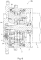
- Fig. 1 is a sectional view showing an example of an industrial device 1 according to a first embodiment of the present invention.
- the industrial device 1 is a movable part of, e.g., a robot arm.
- the industrial device 1 includes a speed reducer 2, a flange 3 provided on an input side, a drive source (e.g., a servo motor) 4, and an output-side device A1.
- the speed reducer 2 includes a casing 12 mounted to the flange 3, an input shaft 14 connected to an output shaft 13 of the drive source 4, and an output shaft 15 connected to the output-side device A1.
- the input shaft 14 and the output shaft 15 are supported so as to be rotatable about an axis AX relative to the casing 12.
- Output of the drive source 4 is input to the speed reducer 2 via the input shaft 14, reduced by the speed reducer 2, and then transmitted to an output-side device A1 via the output shaft 15.
- the output-side device A1 and the flange 3 are rotatable relative to each other.
- the flange 3 is a tubular member having a hollow portion and houses at least a part of the speed reducer 2.
- the drive source 4 is mounted to the flange 3.
- An opening portion in one end of the flange 3 in the direction along the axis AX is closed by the speed reducer 2, and an opening in the other end is closed by the drive source 4.
- the flange 3 contains a tightly closed hollow portion (that is, a lubricant reservoir portion) S.
- the lubricant reservoir portion S contains a lubricant such as a lubricating oil, and the flange 3 also serves as an oil bath.
- the casing 12 of the speed reducer 2 houses, for example, a gear mechanism.
- a space in the casing 12 communicates with the lubricant reservoir portion S in the flange 3.
- rotation of the gear mechanism in the casing 12 causes circulation (or convection) of the lubricant between the space in the casing 12 and the space in the flange 3.
- the conductive substance such as abrasion powder produced in the speed reducer 2 is circulated or discharged into the lubricant reservoir portion S in the flange 3.
- the lubricant reservoir portion S may include a space in the speed reducer 2, in addition to the hollow portion of the flange 3.
- a sensor 5 for sensing the conductive substance contained in the lubricant is installed in the lubricant reservoir portion S.
- a magnet of the sensor 5 causes the conductive substance contained in the lubricant to be accumulated between a pair of electrodes, and the sensor 5 detects the conductive substance in the lubricant by sensing a change in the electric resistance between the pair of electrodes.
- the sensor 5 is installed in a region A shown in Fig. 1 , where the lubricant circulates.
- Fig. 2 shows a configuration of the sensor 5 installed in the industrial device according to an embodiment of the present invention.
- Fig. 2 contains a top view of the sensor 5 and a sectional view along the line A-A of the top view.
- the sensor 5 includes a center electrode (first electrode) 6, a magnet 7, a box-shaped electrode (second electrode) 8, a screw 9, and a resin material 10.
- the center electrode (first electrode) 6 and the magnet 7 are fixed to the box-shaped electrode (second electrode) 8 by the screw 9.
- a signal line 41 shown in Fig. 1 is connected to the box-shaped electrode 8, and a signal line 42 is connected to the center electrode 6.
- the box-shaped electrode 8 is a magnetic member formed of a magnetic material having electric conductivity such as iron, ferrite, or silicon steel.
- the box-shaped electrode 8 has a substantially cylindrical shape and its opening is closed on one end in the axial direction (the bottom in the sectional view of Fig. 2 ) by a bottom portion 8a.
- the box-shaped electrode 8 has a cylindrical box-like shape with an opening at the top.
- the shape of the box-shaped electrode 8 may be a rectangular parallelepiped with an opened top or a polygonal tube with a closed bottom.
- the box-shaped electrode 8 there is disposed a resin material 10, which is a non-magnetic material (an insulator).
- the center electrode (first electrode) 6 and the magnet 7 are formed such that at least a part of them are buried in the central region of the resin material.
- the box-shaped electrode 8 is arranged so as to surround the magnet 7 and the resin material 10.
- the shapes of the magnet 7 and the center electrode 6 are not limited to cylindrical shapes but may be a rectangular parallelepiped, a polygonal column, or the like.
- the outer shape of the center electrode 6 is smaller than the inner periphery of the box-shaped electrode 8. Accordingly, a gap GA is formed between the center electrode 6 and the box-shaped electrode 8 over the entire periphery of the center electrode 6 (so as to surround the center electrode). In other words, the center electrode 6 and the box-shaped electrode 8 are arranged so as to face each other with the gap GA on the resin material 10 interposed therebetween. The gap GA is formed on the resin material 10.
- Output lines are connected to the center electrode 6 and the box-shaped electrode 8, respectively.
- the magnet 7 is either attached or not attached to the bottom of the center electrode 6.
- the magnet 7, which is formed of magnet or an electromagnet may be coated with a nonmagnetic material such as copper, and the signal line 41 or the signal line 42 may be connected to the coating layer.
- the center electrode 6 may also serve as an electrode for the electromagnet.
- the output lines are connected, at the output ends thereof, to a sensor driving circuit (not shown).
- the sensor driving circuit monitors a resistance value of the sensor 5 to predict a failure of the mechanical parts based on variation of the resistance value due to the accumulation of the conductive substance between the electrodes.
- the sensor driving circuit detects the decrease in the electric resistance to predict a failure of the mechanical parts.
- the decrease in the electric resistance may be indicated with an On signal (with electricity passing) and an Off signal (with no electricity passing), so that it is possible to perform sensing between these On and Off states (hereinafter referred to as "digital sensing").
- the sensor driving circuit is connected to a superior control device such as a manipulator in a wired or wireless manner.
- a circuit board 43 in Fig. 1 may transmit outputs of the output lines (an output of the sensor 5) to a superior control device either constantly or intermittently (at regular time intervals) for saving electricity.
- the superior control device may give an alert for demanding maintenance of, for example, the speed reducer 2 with a predetermined notification means (a display or a voice output device).
- the magnet 7 is magnetized to form a magnetic flux path ⁇ A (not shown) in a predetermined direction.
- a strong magnetic flux flows in the gap GA around the center electrode 6.
- the conductive substance from mechanical parts for example, the conductive substance from mechanical parts mixed in the lubricating oil
- the amount of produced conductive substance increases, but this amount greatly differs depending on the size of the industrial device.
- a larger device contains a larger number of mechanical parts or mechanical parts of a larger size, and therefore, more conductive substance is produced.
- a small device produces a small amount of conductive substance, and therefore, it may be difficult that the conductive substance accumulates on the sensor to an amount necessary for proper failure prediction. Therefore, it is preferable to collect the conductive substance onto the sensor 5 to an amount necessary for failure prediction of the mechanical parts.
- the industrial device 1 includes the sensor 5 installed in the region A where the lubricant is circulated.
- the conductive substance contained in the lubricant tends to pass by the sensor 5, so as to be attracted toward the sensor 5. Accordingly, the abrasion powder (conductive substance) can accumulate on the sensor 5 to an amount necessary for proper failure prediction.
- the industrial device 101 includes a flange 3, and at least a part of a speed reducer 2 is housed in the flange 3.
- the flange 3 is a housing member for housing the speed reducer 2, and a drive source (e.g., a motor) 4 is attached to the flange 3.
- the flange 3 is a substantially tubular member having a hollow portion (a lubricant reservoir portion S).
- the lubricant reservoir portion S contains a lubricant (e.g., a lubricating oil).
- the industrial device 101 includes: the lubricant reservoir portion S for containing the lubricant; and the sensor 5 having a pair of electrodes (that is, a first electrode 6 and a second electrode 8) and configured to apply a voltage between the pair of electrodes and allow accumulation of the conductive substance between the electrodes, thereby to sense variation of electric resistance between the pair of electrodes.
- the sensor 5 having a pair of electrodes (that is, a first electrode 6 and a second electrode 8) and configured to apply a voltage between the pair of electrodes and allow accumulation of the conductive substance between the electrodes, thereby to sense variation of electric resistance between the pair of electrodes.
- the industrial device 101 includes a hollow tubular member 17 and a center gear 18 that rotates about the center axis of the tubular member 17.
- the sensor 5 is disposed in the vicinity of the center gear 18.
- the abrasion powder (conductive substance) can accumulate on the sensor 5 to an amount necessary for proper failure prediction.
- the senor 5 is installed in a region facing the center gear 18.
- the rotation of the center gear 18 can cause the lubricant to circulate toward the sensor, such that a larger amount of conductive substance can be collected.
- the abrasion powder (conductive substance) can accumulate on the sensor 5 to an amount necessary for proper failure prediction.
- the industrial device 101 further includes a bracket 19 in the lubricant reservoir portion S, and the sensor 5 is fixed to the bracket 19.
- the sensor is positioned to face the center gear 18, such that a larger amount of conductive substance can be collected. Accordingly, the abrasion powder (conductive substance) can accumulate on the sensor 5 to an amount necessary for proper failure prediction.
- the bracket 19 may be mounted with a screw to an appropriate location in the industrial device 1, but the mounting method can be changed if necessary.
- the industrial device 201 includes a flange 3, and at least a part of a speed reducer 2 is housed in the flange 3.
- the flange 3 is a housing member for housing the speed reducer 2, and a drive source (e.g., a motor) 4 is attached to the flange 3.
- the flange 3 is a substantially tubular member having a hollow portion (a lubricant reservoir portion S).
- the lubricant reservoir portion S contains a lubricant (e.g., a lubricating oil).
- the industrial device 201 includes: the lubricant reservoir portion S for containing the lubricant; and the sensor 5 having a pair of electrodes (that is, a first electrode 6 and a second electrode 8) and configured to apply a voltage between the pair of electrodes and allow accumulation of the conductive substance between the pair of electrodes, thereby to sense variation of electric resistance between the pair of electrodes.
- the sensor 5 having a pair of electrodes (that is, a first electrode 6 and a second electrode 8) and configured to apply a voltage between the pair of electrodes and allow accumulation of the conductive substance between the pair of electrodes, thereby to sense variation of electric resistance between the pair of electrodes.
- the industrial device 201 includes a drive source 4 that is partially housed in a casing 20.
- the drive source 4 is a motor.
- One end portion of the lubricant reservoir portion S is defined by an end surface 22 of the casing 20.
- a drive shaft 21 of the drive source 4 extends through the end surface 22 of the casing 20, and the sensor 5 is fixed to the end surface 22 of the casing 20.
- the rotation of the drive shaft 21 of the drive source 4 can cause the lubricant to circulate toward the sensor 5, such that a larger amount of conductive substance can be collected.
- the abrasion powder conductive substance
- the flange 3 can be shaped more simply, and the connection line of the drive source 4 and the connection line of the sensor 5 can be disposed together more easily.
- the industrial device 301 includes a flange 3, and at least a part of a speed reducer 2 is housed in the flange 3.
- the flange 3 is a housing member for housing the speed reducer 2 including a carrier 23, and a drive source (e.g., a motor) 4 is attached to the flange 3.
- the flange 3 is a substantially tubular member having a hollow portion (the lubricant reservoir portion S).
- the lubricant reservoir portion S contains a lubricant (e.g., a lubricating oil).
- the industrial device 301 includes: the lubricant reservoir portion S for containing the lubricant; and the sensor 5 having a pair of electrodes (that is, a first electrode 6 and a second electrode 8) and configured to apply a voltage between the pair of electrodes and allow accumulation of the conductive substance between the pair of electrodes, thereby to sense variation of electric resistance between the pair of electrodes.
- the sensor 5 having a pair of electrodes (that is, a first electrode 6 and a second electrode 8) and configured to apply a voltage between the pair of electrodes and allow accumulation of the conductive substance between the pair of electrodes, thereby to sense variation of electric resistance between the pair of electrodes.
- the industrial device 1 includes the carrier 23 that is rotatable, and the sensor 5 is fixed to the carrier 23.
- the sensor 5 rotates with the carrier 23, and thus sensor 5 contacts with much lubricant while moving. Accordingly, the abrasion powder (conductive substance) can accumulate on the sensor 5 to an amount necessary for proper failure prediction.
- the industrial device 401 includes a flange 3, and at least a part of a speed reducer 2 including a carrier 23 is housed in the flange 3. On the output side of the speed reducer 2, the carrier 23 is connected to a first member (e.g., a robot arm) 24.
- the flange 3 is a housing member for housing the speed reducer 2, and a drive source (e.g., a motor) 4 is attached to the flange 3.
- the flange 3 is a substantially tubular member having a hollow portion (a lubricant reservoir portion S).
- the lubricant reservoir portion S contains a lubricant (e.g., a lubricating oil).
- the industrial device 401 includes: the lubricant reservoir portion S for containing the lubricant; and the sensor 5 having a pair of electrodes (that is, a first electrode 6 and a second electrode 8) and configured to apply a voltage between the pair of electrodes and allow accumulation of the conductive substance between the pair of electrodes, thereby to sense variation of electric resistance between the pair of electrodes.
- the sensor 5 having a pair of electrodes (that is, a first electrode 6 and a second electrode 8) and configured to apply a voltage between the pair of electrodes and allow accumulation of the conductive substance between the pair of electrodes, thereby to sense variation of electric resistance between the pair of electrodes.
- the industrial device 401 includes the carrier 23 connected to the first member 24.
- the first member 24 is, for example, a robot arm.
- the speed reducer 2 and the members attached thereto can rotate relative to the flange 3, and the sensor 5 is fixed to the first member 24.
- the sensor 5 rotates with the first member 24, and thus sensor 5 contacts with much lubricant while moving. Accordingly, the abrasion powder (conductive substance) can accumulate on the sensor 5 to an amount necessary for proper failure prediction.
- the industrial device 401 includes a crank member (crank mechanism) 25, and the sensor is fixed at such a position as to face the crank member 25.
- the sensor 5 is fixed at such a position as to face the crank member 25 in the axial direction of the crank member 25.
- the sensor 5 contacts with much lubricant while moving in the vicinity of the crank member 25, such that a larger amount of conductive substance can be collected. Accordingly, the abrasion powder (conductive substance) can accumulate on the sensor 5 to an amount necessary for proper failure prediction.
- the industrial device 501 includes a flange 3, and at least a part of a speed reducer 2 is housed in the flange 3.
- the flange 3 is a housing member for housing the speed reducer 2, and a drive source (e.g., a motor) 4 is attached to the flange 3.
- the flange 3 is a substantially tubular member having a hollow portion (a lubricant reservoir portion S).
- the lubricant reservoir portion S contains a lubricant (e.g., a lubricating oil).
- the industrial device 501 includes: the lubricant reservoir portion S for containing the lubricant; and the sensor 5 having a pair of electrodes (that is, a first electrode 6 and a second electrode 8) and configured to apply a voltage between the pair of electrodes and allow accumulation of the conductive substance between the pair of electrodes, thereby to sense variation of electric resistance between the pair of electrodes.
- the sensor 5 having a pair of electrodes (that is, a first electrode 6 and a second electrode 8) and configured to apply a voltage between the pair of electrodes and allow accumulation of the conductive substance between the pair of electrodes, thereby to sense variation of electric resistance between the pair of electrodes.
- the sensor 5 is positioned vertically below the lubricant reservoir portion S.
- the industrial device 501 is disposed such that, for example, a drive shaft of the drive source 4 is orthogonal to the vertical direction.
- the industrial device 501 includes another sensor 5 having a pair of electrodes and configured to allow accumulation of the conductive substance between the pair of electrodes, thereby to sense variation of electric resistance between the pair of electrodes.
- the other sensor 5 is positioned vertically above the lubricant reservoir portion S.
- conductive substance produced upon a failure of the speed reducer precipitates on the sensor 5 disposed above the oil bath.
- the sensor 5 disposed above the oil bath which receives less conductive substance accumulated thereon, reacts a certain period of time after the failure of the speed reducer (more conductive substance is distributed after the failure).
- the sensor 5 disposed vertically below the oil bath that more readily collects conductive substance precipitated thereon is used for failure prediction, and the sensor 5 disposed vertically above the oil bath detects a large amount of conductive substance distributed upon a failure to detect the failure, thus achieving less erroneous sensing operation.
- a sensor group can be constituted that is capable of more reliable and accurate sensing.
Landscapes
- Engineering & Computer Science (AREA)
- Chemical & Material Sciences (AREA)
- Physics & Mathematics (AREA)
- General Physics & Mathematics (AREA)
- Life Sciences & Earth Sciences (AREA)
- Health & Medical Sciences (AREA)
- Analytical Chemistry (AREA)
- Biochemistry (AREA)
- General Health & Medical Sciences (AREA)
- Immunology (AREA)
- Pathology (AREA)
- General Engineering & Computer Science (AREA)
- Mechanical Engineering (AREA)
- Chemical Kinetics & Catalysis (AREA)
- Electrochemistry (AREA)
- Robotics (AREA)
- Food Science & Technology (AREA)
- Medicinal Chemistry (AREA)
- Oil, Petroleum & Natural Gas (AREA)
- General Chemical & Material Sciences (AREA)
- Dispersion Chemistry (AREA)
- Human Computer Interaction (AREA)
- Quality & Reliability (AREA)
- Investigating Or Analyzing Materials By The Use Of Electric Means (AREA)
- General Details Of Gearings (AREA)
- Lubricants (AREA)
- Manipulator (AREA)
Applications Claiming Priority (2)
| Application Number | Priority Date | Filing Date | Title |
|---|---|---|---|
| JP2018154140 | 2018-08-20 | ||
| JP2019139992A JP7319131B2 (ja) | 2018-08-20 | 2019-07-30 | センサを備えた産業装置 |
Publications (2)
| Publication Number | Publication Date |
|---|---|
| EP3623803A2 true EP3623803A2 (de) | 2020-03-18 |
| EP3623803A3 EP3623803A3 (de) | 2020-05-06 |
Family
ID=67659409
Family Applications (1)
| Application Number | Title | Priority Date | Filing Date |
|---|---|---|---|
| EP19192477.8A Pending EP3623803A3 (de) | 2018-08-20 | 2019-08-20 | Industrielle vorrichtung umfassend einen sensor zur erfassung einer leitfähigen substanz in einem schmiermittel |
Country Status (3)
| Country | Link |
|---|---|
| US (1) | US20200057044A1 (de) |
| EP (1) | EP3623803A3 (de) |
| CN (1) | CN110850191A (de) |
Cited By (1)
| Publication number | Priority date | Publication date | Assignee | Title |
|---|---|---|---|---|
| EP3819635A1 (de) * | 2019-11-05 | 2021-05-12 | Nabtesco Corporation | Sensor zur erkennung von leitfähigem abriebpulver in schmieröl |
Families Citing this family (3)
| Publication number | Priority date | Publication date | Assignee | Title |
|---|---|---|---|---|
| CN111855755A (zh) * | 2019-04-26 | 2020-10-30 | 纳博特斯克有限公司 | 传感器 |
| US20220178857A1 (en) * | 2019-04-26 | 2022-06-09 | Nabtesco Corporation | Sensor |
| JP7440240B2 (ja) * | 2019-10-23 | 2024-02-28 | ファナック株式会社 | ロボット |
Citations (1)
| Publication number | Priority date | Publication date | Assignee | Title |
|---|---|---|---|---|
| JP2005331324A (ja) | 2004-05-19 | 2005-12-02 | Ntn Corp | オイルチェックセンサ |
Family Cites Families (14)
| Publication number | Priority date | Publication date | Assignee | Title |
|---|---|---|---|---|
| US4030028A (en) * | 1975-08-13 | 1977-06-14 | Allender David G | Method of and apparatus for detecting conductive particles in an oil flow system |
| US6492787B1 (en) * | 1999-07-23 | 2002-12-10 | Teijin Seiki Co., Ltd. | Speed reducer with rotation detector |
| JP4755357B2 (ja) * | 2001-04-18 | 2011-08-24 | ナブテスコ株式会社 | 減速機 |
| JP4643243B2 (ja) * | 2004-12-13 | 2011-03-02 | Ntn株式会社 | オイルチェックセンサ |
| WO2007046505A1 (ja) * | 2005-10-21 | 2007-04-26 | Nabtesco Corporation | メンテナンス情報出力装置およびメンテナンス情報出力システム |
| JP2010007830A (ja) * | 2008-06-30 | 2010-01-14 | Nabtesco Corp | 歯車装置 |
| KR20180115335A (ko) * | 2010-12-02 | 2018-10-22 | 나부테스코 가부시키가이샤 | 산업 로봇용 감속기 |
| JP5956169B2 (ja) * | 2012-01-25 | 2016-07-27 | ナブテスコ株式会社 | 潤滑油劣化センサーを備えた機械 |
| CN103926276B (zh) * | 2014-03-25 | 2016-01-20 | 天津大学 | 一种在线油液磨粒监测装置及检测方法 |
| US20140347032A1 (en) * | 2014-08-12 | 2014-11-27 | Caterpillar Inc. | Chip detector |
| GB2536473A (en) * | 2015-03-18 | 2016-09-21 | Jaguar Land Rover Ltd | Lubricating system |
| JP6836336B2 (ja) * | 2016-05-20 | 2021-02-24 | ナブテスコ株式会社 | ギア装置 |
| CN107461288B (zh) * | 2016-06-03 | 2018-12-25 | 纳博特斯克有限公司 | 检测装置以及起动装置 |
| JP7086578B2 (ja) * | 2017-11-22 | 2022-06-20 | ナブテスコ株式会社 | センサ |
-
2019
- 2019-08-16 US US16/542,864 patent/US20200057044A1/en active Pending
- 2019-08-20 CN CN201910767944.4A patent/CN110850191A/zh active Pending
- 2019-08-20 EP EP19192477.8A patent/EP3623803A3/de active Pending
Patent Citations (1)
| Publication number | Priority date | Publication date | Assignee | Title |
|---|---|---|---|---|
| JP2005331324A (ja) | 2004-05-19 | 2005-12-02 | Ntn Corp | オイルチェックセンサ |
Cited By (2)
| Publication number | Priority date | Publication date | Assignee | Title |
|---|---|---|---|---|
| EP3819635A1 (de) * | 2019-11-05 | 2021-05-12 | Nabtesco Corporation | Sensor zur erkennung von leitfähigem abriebpulver in schmieröl |
| US11346871B2 (en) | 2019-11-05 | 2022-05-31 | Nabtesco Corporation | Sensor |
Also Published As
| Publication number | Publication date |
|---|---|
| EP3623803A3 (de) | 2020-05-06 |
| US20200057044A1 (en) | 2020-02-20 |
| CN110850191A (zh) | 2020-02-28 |
Similar Documents
| Publication | Publication Date | Title |
|---|---|---|
| EP3623803A2 (de) | Industrielle vorrichtung umfassend einen sensor zur erfassung einer leitfähigen substanz in einem schmiermittel | |
| CN109813208B (zh) | 传感器和机构 | |
| US20180275083A1 (en) | Sensor | |
| US11346871B2 (en) | Sensor | |
| US11852623B2 (en) | Magnetic sensor for capturing metal wear particles in suspension in a lubrication fluid | |
| US11499931B2 (en) | Sensor | |
| JP7452980B2 (ja) | センサ | |
| JP7101486B2 (ja) | センサ | |
| JP7319131B2 (ja) | センサを備えた産業装置 | |
| EP3961201A1 (de) | Sensor | |
| US20230243768A1 (en) | Abnormality detecting device and mechanical device | |
| US20240011887A1 (en) | Abnormality detecting device | |
| CN118112060A (zh) | 传感器 |
Legal Events
| Date | Code | Title | Description |
|---|---|---|---|
| PUAI | Public reference made under article 153(3) epc to a published international application that has entered the european phase |
Free format text: ORIGINAL CODE: 0009012 |
|
| STAA | Information on the status of an ep patent application or granted ep patent |
Free format text: STATUS: THE APPLICATION HAS BEEN PUBLISHED |
|
| AK | Designated contracting states |
Kind code of ref document: A2 Designated state(s): AL AT BE BG CH CY CZ DE DK EE ES FI FR GB GR HR HU IE IS IT LI LT LU LV MC MK MT NL NO PL PT RO RS SE SI SK SM TR |
|
| AX | Request for extension of the european patent |
Extension state: BA ME |
|
| PUAL | Search report despatched |
Free format text: ORIGINAL CODE: 0009013 |
|
| AK | Designated contracting states |
Kind code of ref document: A3 Designated state(s): AL AT BE BG CH CY CZ DE DK EE ES FI FR GB GR HR HU IE IS IT LI LT LU LV MC MK MT NL NO PL PT RO RS SE SI SK SM TR |
|
| AX | Request for extension of the european patent |
Extension state: BA ME |
|
| RIC1 | Information provided on ipc code assigned before grant |
Ipc: B25J 13/08 20060101ALI20200330BHEP Ipc: B25J 19/00 20060101ALI20200330BHEP Ipc: G01M 13/021 20190101ALI20200330BHEP Ipc: F16H 57/04 20100101ALI20200330BHEP Ipc: G01N 27/04 20060101AFI20200330BHEP Ipc: F16H 57/01 20120101ALI20200330BHEP Ipc: F16H 61/12 20100101ALI20200330BHEP Ipc: G01N 33/28 20060101ALI20200330BHEP Ipc: F01M 11/10 20060101ALI20200330BHEP |
|
| STAA | Information on the status of an ep patent application or granted ep patent |
Free format text: STATUS: REQUEST FOR EXAMINATION WAS MADE |
|
| 17P | Request for examination filed |
Effective date: 20201106 |
|
| RBV | Designated contracting states (corrected) |
Designated state(s): AL AT BE BG CH CY CZ DE DK EE ES FI FR GB GR HR HU IE IS IT LI LT LU LV MC MK MT NL NO PL PT RO RS SE SI SK SM TR |
|
| STAA | Information on the status of an ep patent application or granted ep patent |
Free format text: STATUS: EXAMINATION IS IN PROGRESS |
|
| 17Q | First examination report despatched |
Effective date: 20220211 |
|
| P01 | Opt-out of the competence of the unified patent court (upc) registered |
Effective date: 20230523 |