EP3623213A1 - Vehicle seat provided with a removable shelf and vehicle comprising such a seat - Google Patents
Vehicle seat provided with a removable shelf and vehicle comprising such a seat Download PDFInfo
- Publication number
- EP3623213A1 EP3623213A1 EP19197232.2A EP19197232A EP3623213A1 EP 3623213 A1 EP3623213 A1 EP 3623213A1 EP 19197232 A EP19197232 A EP 19197232A EP 3623213 A1 EP3623213 A1 EP 3623213A1
- Authority
- EP
- European Patent Office
- Prior art keywords
- seat
- backrest
- tablet
- rear face
- magnets
- Prior art date
- Legal status (The legal status is an assumption and is not a legal conclusion. Google has not performed a legal analysis and makes no representation as to the accuracy of the status listed.)
- Granted
Links
- 229910052751 metal Inorganic materials 0.000 claims description 19
- 239000002184 metal Substances 0.000 claims description 19
- 230000002787 reinforcement Effects 0.000 claims description 6
- 238000012423 maintenance Methods 0.000 description 2
- 230000003014 reinforcing effect Effects 0.000 description 2
- 208000031968 Cadaver Diseases 0.000 description 1
- 229910052779 Neodymium Inorganic materials 0.000 description 1
- 238000010073 coating (rubber) Methods 0.000 description 1
- 230000000295 complement effect Effects 0.000 description 1
- 230000014759 maintenance of location Effects 0.000 description 1
- 239000000463 material Substances 0.000 description 1
- QEFYFXOXNSNQGX-UHFFFAOYSA-N neodymium atom Chemical compound [Nd] QEFYFXOXNSNQGX-UHFFFAOYSA-N 0.000 description 1
- 238000005192 partition Methods 0.000 description 1
- 229910000859 α-Fe Inorganic materials 0.000 description 1
Images

Classifications
-
- B—PERFORMING OPERATIONS; TRANSPORTING
- B60—VEHICLES IN GENERAL
- B60N—SEATS SPECIALLY ADAPTED FOR VEHICLES; VEHICLE PASSENGER ACCOMMODATION NOT OTHERWISE PROVIDED FOR
- B60N3/00—Arrangements or adaptations of other passenger fittings, not otherwise provided for
- B60N3/001—Arrangements or adaptations of other passenger fittings, not otherwise provided for of tables or trays
- B60N3/002—Arrangements or adaptations of other passenger fittings, not otherwise provided for of tables or trays of trays
-
- B—PERFORMING OPERATIONS; TRANSPORTING
- B60—VEHICLES IN GENERAL
- B60N—SEATS SPECIALLY ADAPTED FOR VEHICLES; VEHICLE PASSENGER ACCOMMODATION NOT OTHERWISE PROVIDED FOR
- B60N2/00—Seats specially adapted for vehicles; Arrangement or mounting of seats in vehicles
- B60N2/02—Seats specially adapted for vehicles; Arrangement or mounting of seats in vehicles the seat or part thereof being movable, e.g. adjustable
- B60N2/20—Seats specially adapted for vehicles; Arrangement or mounting of seats in vehicles the seat or part thereof being movable, e.g. adjustable the back-rest being tiltable, e.g. to permit easy access
- B60N2/206—Seats specially adapted for vehicles; Arrangement or mounting of seats in vehicles the seat or part thereof being movable, e.g. adjustable the back-rest being tiltable, e.g. to permit easy access to a position in which it can be used as a support for objects, e.g. as a tray
Definitions
- the present invention relates to a vehicle seat equipped with a removable tablet, as well as a vehicle equipped with such a seat.
- a vehicle equipped with such a seat relates to a seat whose back can be folded back onto the seat, and whose back is equipped with a removable shelf and which can be fixed in writing position on the folded back.
- This type of seat is mainly used in utility vehicles.
- An example of such a seat is described in the document FR2982547A1 .
- the seats fitted with writing tablets are very practical and give full satisfaction.
- the present invention meets this objective and provides a motor vehicle seat comprising a seat and a folding backrest comprising a rear face provided with a tablet, the backrest being able to be folded back onto the seat so as to bring its rear face into a substantially horizontal position, the tablet being removable and affixed against the rear face of the backrest inside a housing produced on the rear face of the seat backrest, characterized in that said tablet comprises a plurality of magnets and in that said seat has on its rear face elements for receiving said magnets intended to receive the magnets of the tablet when the latter is placed in the housing.
- the tablet is reinforced in its usual holding behind the backrest.
- the tablet can be placed and maintained in other locations in the vehicle, in particular along the metal surfaces, for example inside the loading space. The tablet is thus not only used for writing and consulting documents inside the passenger compartment, but also in the loading space.
- the invention also relates to a vehicle comprising a row of at least two seats, at least one of which conforms to any one of the preceding characteristics and / or a tablet according to the preceding characteristics.
- front In the context of the present application, the terms “front”, “rear”, “left”, “right”, “lower”, “upper” are understood to mean a reference for motor vehicles comprising a first longitudinal axis X, horizontal and oriented from rear to front, that is to say from the boot to the hood, a transverse axis Y and a vertical axis Z directed from the bottom up, i.e. from the floor to the roof of the vehicle, with a seat arranged in the vehicle, the seatback being in the position of use facing the road.
- the same references designate identical or similar elements.
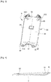
- the figure 1 is a rear perspective view of a seat provided with a tablet according to the invention.
- the seat includes a seat 2 and a backrest 3 provided with a rear shell 31 against which a shelf 9 is placed.
- the seat applying the invention is in our example a first row utility vehicle central seat.
- the seat 1 comprises a backrest 3 which can be folded back onto the seat 2 so as to bring its rear face into a substantially position horizontal.
- the back side of the backrest is covered with a plastic back shell 31, in which is housed a housing 32 inside which a removable shelf 9 can be placed.
- the tablet is placed inside the housing and figure 2 , the tablet is removed from the housing.
- the tablet extracted from the housing, can then be placed in the writing position, that is to say arranged inside grooves 37, 371, 372, 373, 374 located in the upper part of the back of the backrest, when the backrest 3 is in the folded position.
- the grooves 37, 371, 372, 373, 374 are four in number and arranged in a cross shape, two grooves being aligned along a first axis and two other grooves being aligned along a second axis.
- the shelf 9 comprises an elongated planar body 94, having at one of its ends along the length an inclined edge 95 defining an inner face 98 and an outer face 99 of the shelf.
- the inner face 98 is visible in figure 3 and the outer face 99 is visible at figure 1 and in figure 2 .
- the tablet is substantially rectangular.
- the tablet comprises a plurality of magnets 91, 92, 93 projecting from the inner face.
- the tablet 9 is in contact with the rear face of the seat back by means of the magnets 91, 92, 93.
- the seat has on its rear face 31 receiving elements 34, 35, 36, 39 of said magnets intended to receive the magnets of the tablet 9 when the latter is placed in the housing 32.
- the seat is provided with receiving elements 34, 35, 36, 39 which include recesses 34, 35, 36 and the shelf 9 is in contact with the rear face of the seat back 31 at least in part by means of the magnets 91, 92, 93 inserted inside the recesses 34, 35, 36.
- the tablet includes three magnets and the housing 32 on the back of the backrest 31 has on the side of the seat, a recess 33 and three recesses 34, 35, 36.
- the recesses 34, 35, 36 are substantially circular shape.
- the tablet is arranged in the housing 32 so that its inclined edge 95 comes to be inserted in the recess 33, and the three magnets 91, 92, 93 inserted in the three recesses 34, 35, 36.
- the recesses in which s 'engage the three magnets 91, 92, 93 are deep and allow to strengthen the maintenance of the tablet in its housing behind the back thanks to the maintenance achieved by the contact of the magnets with the side walls of the orifice of the recess.
- the magnets are in contact with the internal surface of the recess by their external surface 910, 920, 930.
- the fixing can be further reinforced by the placement of the recesses 34, 35, 36 on the seat near the metal reinforcing portions.
- the receiving elements 34, 35, 36, 39 consist of a metal bar 391 and the shelf 9 is in contact with the rear face of the seat back 31 at least in part by means of the magnets 91, 92, 93 arranged at the contact of the metal bar 391.
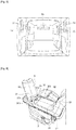
- the magnets 91, 92, 93 not only make it possible to strengthen the fixing of the shelf 9 in the housing behind the backrest, they also allow the shelf 9 to be positioned along any flat metallic surface 51, 52 , 53, 54, 55 present inside and outside the vehicle, as visible in figure 5 . These surfaces 51, 52, 53, 54, 55 are located on the side partitions and the doors defining the loading space.
- the attachment to the lateral surfaces is practical, and advantageously allows, for example, during operations to delivery with a utility vehicle, to the occupant not to lose the tablet 9 and avoid placing the tablet 9 on the vehicle floor.
- the tablet comprises three magnets 91, 92, 93 on its rear face 98 and these are distributed according to two distinct heights, namely two magnets are placed aligned in the upper part and a magnet in the lower part of the tablet.
- the two magnets in the upper part make it possible to strengthen the fixing of the tablet in the upper part and thus ensure better attachment to the support in the upper part.
- the retention of the tablet in the case where it is placed vertically in writing mode, is thus improved, in particular in the case where the upper part of the tablet is arranged upwards on the support.
- a distribution of the magnets in two separate alignments also makes it easier to remove the tablet from the walls against which it is fixed, by providing a free passage between the two alignments, this passage being usable for gripping with the fingers of hand of the tablet.
- the tablet comprises a single magnet 91 at the bottom, and this is arranged between two side lobes 96, 97, in detail in the junction space between the two side lobes.
- the side lobes 96, 97 are in particular used for fixing in writing mode behind the back.
- the grooves 37, 371, 372, 373, 374 comprise a holding space 38 located at the intersection of the four grooves, the holding space comprising a recess 380 intended to receive a magnet 91, 92, 93 of the tablet when the tablet is placed in the upright position.
- the holding space comprises a metal reinforcement 381 intended to promote the attraction of at least one magnet 91, 92, 93 of the tablet, when the latter is placed in the upright position, the metal reinforcement is intended to promote the attraction of at least one magnet of the tablet, in particular the magnet placed in the lower part, and thus making it possible to strengthen the fixing in writing position of the tablet on the seat.
- the magnet 91 in the lower part is located substantially in the middle of the tablet, at equal distance likewise from the magnets 92, 93 located in the upper part of the tablet, which makes it possible to balance the attraction exerted by the three magnets towards the support.
- the three magnets 91, 92, 93 have a protruding surface portion included in the same plane P1.
- This plan is that of a support on which the rear face of the tablet would be positioned.
- An attachment of the three magnets, and therefore of the tablet, is advantageously possible on a flat support.
- Examples of mounting surfaces are disclosed in figure 5 , showing a view of the cargo space of a utility vehicle.
- the fixing surfaces 51, 52, 53, 54, 55 are located on the interior side walls of the vehicle and along the rear doors in particular.
- the tablet can also adhere to a surface which is not necessarily strictly flat, with reduced adhesion, however, since it depends on the proximity of the magnets to the support.
- the shelf is intended to be used exclusively when stationary, it must be replaced at the back of the backrest for driving.
- the magnets used may for example be magnets of circular shape, which makes it possible to reinforce the centering when the tablet is fixed in its housing, and made of neodymium material with rubber coating on their external surface in order to protect the painted surfaces of the vehicle against scratches that could be caused when handling the tablet. Ferrite magnets can also alternatively be envisaged.
- the tablet is used as follows: After disengagement of its housing on the back of the backrest by the user, it can be placed in the grooves 37, 371, 372, 373, 374 at the top of the backrest opposite the driver or d 'an occupant passenger, or be put on hold easily, on any metal surface inside in the cargo space or outside the vehicle, at the choice of the user. In all these positions, the magnets 91, 92 and 93 come as reinforcement or fully secure it to the support.
- the invention is in no way limited to the embodiments described.
Abstract
Siège (1) de véhicule automobile comprenant une assise (2) et un dossier repliable comportant une face arrière (31) munie d'une tablette (9), le dossier étant apte à être replié sur l'assise (2) de manière à amener sa face arrière (31) dans une position sensiblement horizontale, la tablette (9) étant amovible et apposée contre la face arrière (31) du dossier à l'intérieur d'un logement (32) réalisé en face arrière de dossier de siège (31), ladite tablette (9) comprenant une pluralité d'aimants et ledit siège présentant sur sa face arrière (31) des éléments de réception (34, 35, 36) desdits aimants destinés à accueillir les aimants de la tablette (9) lorsque cette dernière est placée dans le logement (32).Motor vehicle seat (1) comprising a seat (2) and a folding backrest comprising a rear face (31) provided with a shelf (9), the backrest being able to be folded back onto the seat (2) so as to bringing its rear face (31) into a substantially horizontal position, the shelf (9) being removable and affixed against the rear face (31) of the backrest inside a housing (32) produced on the rear face of the seat backrest (31), said tablet (9) comprising a plurality of magnets and said seat having on its rear face (31) receiving elements (34, 35, 36) of said magnets intended to receive the magnets of the tablet (9) when the latter is placed in the housing (32).
Description
La présente invention concerne un siège de véhicule équipé d'une tablette amovible, ainsi qu'un véhicule équipé d'un tel siège. En particulier, elle concerne un siège dont le dossier peut se replier sur l'assise, et dont le dossier est équipé d'une tablette amovible et qui peut être fixée en position écritoire sur le dossier replié. Ce type de siège équipe principalement les véhicules de type utilitaire. Un exemple de tel siège est décrit dans le document
Dans le cas des véhicules utilitaires, les sièges équipés de tablettes écritoire sont très pratiques et donnent pleinement satisfaction. Néanmoins, il peut être souhaitable d'améliorer encore ces équipements afin notamment que ceux-ci puissent assurer des fonctions supplémentaires et complémentaires dans le véhicule.
La présente invention répond à cet objectif et propose un siège de véhicule automobile comprenant une assise et un dossier repliable comportant une face arrière munie d'une tablette, le dossier étant apte à être replié sur l'assise de manière à amener sa face arrière dans une position sensiblement horizontale, la tablette étant amovible et apposée contre la face arrière du dossier à l'intérieur d'un logement réalisé en face arrière de dossier de siège, caractérisée en ce que ladite tablette comprend une pluralité d'aimants et en ce que ledit siège présente sur sa face arrière des éléments de réception desdits aimants destinés à accueillir les aimants de la tablette lorsque cette dernière est placée dans le logement.
Avantageusement, grâce aux aimants et aux éléments de réception en face arrière du siège, la tablette est renforcée dans son maintien habituel en arrière de dossier. Avantageusement, grâce aux aimants, la tablette peut être placée et maintenue en d'autres localisations dans le véhicule, notamment le long des surfaces métalliques, par exemple à l'intérieur de l'espace de chargement. La tablette est ainsi non seulement utilisée pour l'écriture et la consultation de documents à l'intérieur de l'habitacle, mais aussi dans l'espace de chargement.The present invention relates to a vehicle seat equipped with a removable tablet, as well as a vehicle equipped with such a seat. In particular, it relates to a seat whose back can be folded back onto the seat, and whose back is equipped with a removable shelf and which can be fixed in writing position on the folded back. This type of seat is mainly used in utility vehicles. An example of such a seat is described in the document
In the case of commercial vehicles, the seats fitted with writing tablets are very practical and give full satisfaction. However, it may be desirable to further improve this equipment so that it can perform additional and complementary functions in the vehicle.
The present invention meets this objective and provides a motor vehicle seat comprising a seat and a folding backrest comprising a rear face provided with a tablet, the backrest being able to be folded back onto the seat so as to bring its rear face into a substantially horizontal position, the tablet being removable and affixed against the rear face of the backrest inside a housing produced on the rear face of the seat backrest, characterized in that said tablet comprises a plurality of magnets and in that said seat has on its rear face elements for receiving said magnets intended to receive the magnets of the tablet when the latter is placed in the housing.
Advantageously, thanks to the magnets and the receiving elements on the rear face of the seat, the tablet is reinforced in its usual holding behind the backrest. Advantageously, thanks to the magnets, the tablet can be placed and maintained in other locations in the vehicle, in particular along the metal surfaces, for example inside the loading space. The tablet is thus not only used for writing and consulting documents inside the passenger compartment, but also in the loading space.
Dans des formes de réalisation préférées de l'invention, on a en outre recours à l'une et/ou à l'autre des dispositions suivantes prises seules ou en combinaison :
- Les éléments de réception comprennent des évidements et ladite tablette est en contact avec la face arrière de dossier de siège au moins en partie au moyen desdits aimants insérés à l'intérieur des évidements.
- Les évidements sont de forme circulaire.
- Le dossier comprend au moins une portion métallique placée à proximité dudit au moins un évidement, afin de favoriser l'attraction des aimants de la tablette pour ladite portion métallique et ainsi renforcer la fixation de la tablette à la face arrière du dossier.
- Les éléments de réception sont constitués d'au moins une barre métallique et ladite tablette est en contact avec la face arrière de dossier de siège au moins en partie au moyen desdits aimants disposés au contact de la barre métallique.
- Le logement en face arrière de dossier présente à proximité de l'assise, un renfoncement et au moins un évidement disposé en partie sur le renfoncement et la tablette comporte un corps plan terminé par un bord incliné, ladite tablette étant disposée dans le logement de sorte que son bord incliné vienne s'insérer dans ledit renfoncement, et au moins un aimant soit inséré dans le au moins évidement.
- La face arrière du dossier est dotée d'au moins deux rainures alignées suivant un même axe, permettant de recevoir la tablette et la maintenir dans une position dressée lorsque ledit dossier est placé sensiblement horizontal, les deux rainures étant séparées par un espace de maintien, l'espace de maintien comprenant un évidement destiné à recevoir un aimant de la tablette, lorsque cette dernière est placée en position dressée.
- La face arrière du dossier est dotée d'au moins deux rainures alignées suivant un même axe, permettant de recevoir la tablette et la maintenir dans une position dressée lorsque ledit dossier est placé sensiblement horizontal, les deux rainures étant séparées par un espace de maintien, l'espace de maintien comprenant un renforcement métallique destiné à favoriser l'attraction d'au moins un aimant de la tablette, lorsque cette dernière est placée en position dressée.
- The receiving elements include recesses and said shelf is in contact with the rear face of the seat back at least in part by means of said magnets inserted inside the recesses.
- The recesses are circular in shape.
- The file comprises at least one metal portion placed near said at least one recess, in order to promote the attraction of the magnets of the tablet for said metal portion and thus strengthen the fixing of the tablet to the rear face of the file.
- The receiving elements consist of at least one metal bar and said shelf is in contact with the rear face of the seat back at least in part by means of said magnets arranged in contact with the metal bar.
- The housing on the rear face of the backrest has, near the seat, a recess and at least one recess partially arranged on the recess and the shelf has a flat body terminated by an inclined edge, said shelf being arranged in the housing so that its inclined edge comes to be inserted in said recess, and at least one magnet is inserted in the at least recess.
- The rear face of the backrest is provided with at least two grooves aligned along the same axis, making it possible to receive the shelf and keep it in an upright position when said backrest is placed substantially horizontal, the two grooves being separated by a holding space, the holding space comprising a recess intended to receive a magnet of the tablet, when the latter is placed in the upright position.
- The rear face of the backrest is provided with at least two grooves aligned along the same axis, making it possible to receive the shelf and keep it in an upright position when said backrest is placed substantially horizontal, the two grooves being separated by a holding space, the holding space comprising a metal reinforcement intended to promote the attraction of at least one magnet of the tablet, when the latter is placed in the upright position.
L'invention concerne aussi un véhicule comportant une rangée d'au moins deux sièges, dont au moins un siège conforme à l'une quelconque des caractéristiques précédentes et/ ou une tablette selon les caractéristiques précédentes.The invention also relates to a vehicle comprising a row of at least two seats, at least one of which conforms to any one of the preceding characteristics and / or a tablet according to the preceding characteristics.
D'autres caractéristiques et avantages de l'invention apparaîtront au cours de la description suivante de plusieurs de ses formes de réalisation, données à titre d'exemples non limitatifs, en regard des dessins joints.
Sur les dessins:
- [
Fig. 1 ] représente une vue arrière du siège selon l'invention - [
Fig. 2 ] est une vue latérale du siège avec un dossier replié sur l'assise en position tablette - [
Fig. 3 ] est une vue arrière de la tablette avec ses aimants - [
Fig. 4 ] est une vue de profil de la tablette - [
Fig. 5 ] est une vue de l'espace de chargement d'un véhicule utilitaire - [
Fig. 6 ] est une vue latérale du siège avec un dossier replié sur l'assise en position tablette dans un mode de réalisation alternatif
In the drawings:
- [
Fig. 1 ] shows a rear view of the seat according to the invention - [
Fig. 2 ] is a side view of the seat with a folded backrest on the seat in the tablet position - [
Fig. 3 ] is a rear view of the tablet with its magnets - [
Fig. 4 ] is a side view of the tablet - [
Fig. 5 ] is a view of the cargo space of a commercial vehicle - [
Fig. 6 ] is a side view of the seat with a folded backrest on the seat in the tablet position in an alternative embodiment
Dans le contexte de la présente demande, les termes « avant », « arrière », « gauche », « droite », « inférieur », « supérieur », s'entendent en référence à un repère des véhicules automobiles comprenant un premier axe longitudinal X, horizontal et orienté de l'arrière vers l'avant, c'est-à-dire du coffre vers le capot, un axe transversal Y et un axe vertical Z dirigé du bas vers le haut, c'est-à-dire du plancher vers le toit du véhicule, avec un siège disposé dans le véhicule, le dossier du siège étant en position d'utilisation face à la route.
Par ailleurs, sur les différentes figures, les mêmes références désignent des éléments identiques ou similaires.In the context of the present application, the terms “front”, “rear”, “left”, “right”, “lower”, “upper” are understood to mean a reference for motor vehicles comprising a first longitudinal axis X, horizontal and oriented from rear to front, that is to say from the boot to the hood, a transverse axis Y and a vertical axis Z directed from the bottom up, i.e. from the floor to the roof of the vehicle, with a seat arranged in the vehicle, the seatback being in the position of use facing the road.
Furthermore, in the different figures, the same references designate identical or similar elements.
La
Comme visible en
Comme visible en
La tablette 9 est en contact avec la face arrière de dossier de siège au moyen des aimants 91, 92, 93. Le siège présente sur sa face arrière 31 des éléments de réception 34, 35, 36, 39 desdits aimants destinés à accueillir les aimants de la tablette 9 lorsque cette dernière est placée dans le logement 32.
Dans le mode de réalisation décrit en
La
De plus, les aimants 91, 92, 93 permettent non seulement de renforcer la fixation de la tablette 9 dans le logement en arrière de dossier, ils permettent aussi à la tablette 9 d'être positionnée le long de toute surface métallique plane 51, 52, 53, 54, 55 présente à l'intérieur et à l'extérieur du véhicule, comme visible en
De manière préférentielle, comme visible en
Une répartition des aimants suivant deux alignements distincts permet de plus, de faciliter le retrait de la tablette des parois contre lesquelles celle-ci est fixée, en offrant un passage libéré entre les deux alignements, ce passage étant utilisable pour la préhension avec les doigts de la main de la tablette. De manière préférentielle, la tablette comprend un unique aimant 91 en partie basse, et celui-ci est disposé entre deux lobes latéraux 96, 97, en détail dans l'espace de jonction entre les deux lobes latéraux. Les lobes latéraux 96, 97 sont notamment utilisés pour la fixation en mode écritoire en arrière de dossier. Ces derniers sont ainsi placés à l'intérieur des rainures 37, 371, 372, 373, 374 pour le positionnement de la tablette en mode écritoire. L'aimant 91 en partie basse, est fixé à la jonction des deux lobes, et permet de renforcer encore l'adhérence de la tablette au support lorsque celle-ci est disposée verticalement, notamment de façon dressée en mode écritoire. Dans un mode de réalisation particulier, les rainures 37, 371, 372, 373, 374 comprennent un espace de maintien 38 situé au croisement des quatre rainures, l'espace de maintien comprenant un évidement 380 destiné à recevoir un aimant 91, 92, 93 de la tablette lorsque la tablette est placée en position dressée. Dans un mode de réalisation alternatif ou en complément, l'espace de maintien comprend un renforcement métallique 381 destiné à favoriser l'attraction d'au moins un aimant 91, 92, 93 de la tablette, lorsque cette dernière est placée en position dressée, le renforcement métallique est destiné à favoriser l'attraction d'au moins un aimant de la tablette, notamment l'aimant placé en partie basse, et permettant ainsi de renforcer la fixation en position écritoire de la tablette sur le siège.
Dans le mode de réalisation décrit, l'aimant 91 en partie basse est situé sensiblement au milieu de la tablette, à égale distance de même des aimants 92, 93 localisés en partie haute de tablette, ce qui permet de d'équilibrer l'attraction exercée par les trois aimants vers le support. Comme visible plus en détail en
Les aimants utilisés peuvent être par exemple des aimants de forme circulaire, ce qui permet de renforcer le centrage lors de la fixation de la tablette dans son logement, et en matière néodyme avec revêtement en caoutchouc sur leur surface externe afin de protéger les surfaces peintes du véhicule contre les rayures qui pourraient être occasionnées lors de la manipulation de la tablette. Des aimants en ferrite peuvent être aussi alternativement être envisagés.
La tablette est utilisée de la façon suivante : Après désengagement de son logement en face arrière de dossier par l'usager, elle peut être placée dans les rainures 37, 371, 372, 373, 374 en haut de dossier en regard du conducteur ou d'un occupant passager, ou être mise en attente de façon aisée, sur une quelconque surface métallique à l'intérieur dans l'espace de chargement ou à l'extérieur du véhicule, au choix de l'utilisateur. Dans toutes ces positions, les aimants 91, 92 et 93 viennent en renfort ou assurent intégralement la fixation au support. L'invention n'est en aucun cas limitée aux modes de réalisation décrits.The
As visible in
As visible in
The
In the embodiment described in
The
In addition, the
Preferably, as visible in
A distribution of the magnets in two separate alignments also makes it easier to remove the tablet from the walls against which it is fixed, by providing a free passage between the two alignments, this passage being usable for gripping with the fingers of hand of the tablet. Preferably, the tablet comprises a
In the embodiment described, the
The magnets used may for example be magnets of circular shape, which makes it possible to reinforce the centering when the tablet is fixed in its housing, and made of neodymium material with rubber coating on their external surface in order to protect the painted surfaces of the vehicle against scratches that could be caused when handling the tablet. Ferrite magnets can also alternatively be envisaged.
The tablet is used as follows: After disengagement of its housing on the back of the backrest by the user, it can be placed in the
Claims (9)
Applications Claiming Priority (1)
| Application Number | Priority Date | Filing Date | Title |
|---|---|---|---|
| FR1871030A FR3085899B1 (en) | 2018-09-13 | 2018-09-13 | VEHICLE SEAT EQUIPPED WITH A REMOVABLE SHELF AND VEHICLE INCLUDING SUCH SEAT |
Publications (2)
| Publication Number | Publication Date |
|---|---|
| EP3623213A1 true EP3623213A1 (en) | 2020-03-18 |
| EP3623213B1 EP3623213B1 (en) | 2021-10-27 |
Family
ID=65201620
Family Applications (1)
| Application Number | Title | Priority Date | Filing Date |
|---|---|---|---|
| EP19197232.2A Active EP3623213B1 (en) | 2018-09-13 | 2019-09-13 | Vehicle seat provided with a removable shelf and vehicle comprising such a seat |
Country Status (2)
| Country | Link |
|---|---|
| EP (1) | EP3623213B1 (en) |
| FR (1) | FR3085899B1 (en) |
Citations (3)
| Publication number | Priority date | Publication date | Assignee | Title |
|---|---|---|---|---|
| FR2924387A3 (en) * | 2007-11-30 | 2009-06-05 | Renault Sas | Writing support for use in storage case of motor vehicle, has clamp for attaching paper sheet or stack of sheets on side of plate when support is fixed on vertical surface in position, which is different from functional position |
| FR2982547A1 (en) | 2011-11-16 | 2013-05-17 | Renault Sa | VEHICLE SEAT EQUIPPED WITH A REMOVABLE TABLET |
| FR3023515A1 (en) * | 2014-07-11 | 2016-01-15 | Faurecia Sieges Automobile | TABLET FOR ARMREST FOR SEAT OF MOTOR VEHICLE |
-
2018
- 2018-09-13 FR FR1871030A patent/FR3085899B1/en not_active Expired - Fee Related
-
2019
- 2019-09-13 EP EP19197232.2A patent/EP3623213B1/en active Active
Patent Citations (3)
| Publication number | Priority date | Publication date | Assignee | Title |
|---|---|---|---|---|
| FR2924387A3 (en) * | 2007-11-30 | 2009-06-05 | Renault Sas | Writing support for use in storage case of motor vehicle, has clamp for attaching paper sheet or stack of sheets on side of plate when support is fixed on vertical surface in position, which is different from functional position |
| FR2982547A1 (en) | 2011-11-16 | 2013-05-17 | Renault Sa | VEHICLE SEAT EQUIPPED WITH A REMOVABLE TABLET |
| FR3023515A1 (en) * | 2014-07-11 | 2016-01-15 | Faurecia Sieges Automobile | TABLET FOR ARMREST FOR SEAT OF MOTOR VEHICLE |
Also Published As
| Publication number | Publication date |
|---|---|
| FR3085899B1 (en) | 2020-09-04 |
| FR3085899A1 (en) | 2020-03-20 |
| EP3623213B1 (en) | 2021-10-27 |
Similar Documents
| Publication | Publication Date | Title |
|---|---|---|
| FR2979865A1 (en) | INSTALLATION AND RETENTION OF SLIDING ARMOR COMPONENTS | |
| EP3359405A1 (en) | Battery support arrangement for hybrid vehicle | |
| FR2955077A1 (en) | Motor vehicle i.e. car, has reinforcement element placed at side of longitudinal tunnel that is utilized for placing battery, where another side of longitudinal tunnel is equipped with access unit for accessing battery | |
| EP3284125B1 (en) | Device for mounting and protecting a battery, and corresponding vehicle | |
| EP3623213B1 (en) | Vehicle seat provided with a removable shelf and vehicle comprising such a seat | |
| EP2222507B1 (en) | A support for one or more elements which are intended to be fastened to a motor vehicle structure | |
| FR3085900A1 (en) | REMOVABLE VEHICLE SEAT TABLET AND VEHICLE EQUIPPED WITH SUCH A TABLET. | |
| FR2934830A1 (en) | FIXING STRUCTURE FOR INPUTTING WASHER | |
| FR3002753A1 (en) | MOTOR VEHICLE COMPRISING A SEAT WITH A REMOVABLE SEAT MEMBER TO RELEASE THE ACCESS TO A REINFORCEMENT OF ITS INTERNAL STRUCTURE | |
| FR3055476A1 (en) | DIVIDED CONNECTOR | |
| EP3448701B1 (en) | Vehicle door with reinforcer and vehicle comprising such a door | |
| FR2907396A1 (en) | Load receiving area arrangement for motor vehicle, has front edge of load area with articulated part that occupies position in which part extends in extension of area to cover part of row of rear seat in retracted position | |
| EP1640205A2 (en) | Module enchoring device in a vehicle | |
| EP2864159B1 (en) | Device for stowing objects in a vehicle and corresponding vehicle | |
| EP3735364B1 (en) | Support structure for an element to be fixed to a front pillar of a vehicle | |
| FR3063126B1 (en) | PROTECTION FOR ELECTRICAL CONDUCTOR SHEATH OR MOTOR VEHICLE FLUID | |
| FR2501309A1 (en) | Panel assembly profile for caissons - has key piece inserted into groove in bottom of U=section panel retaining profile | |
| FR3058978A1 (en) | AUTOMOBILE TRUCK VEHICLE WITH A PIECE DELIMITATING A SPACE FOR A WHEEL OF SUPPORT OR AS A SUPPORT FOR A WHEEL | |
| FR3058108A1 (en) | FLOOR DEVICE FOR VEHICLE AND VEHICLE COMPRISING SAID FLOOR DEVICE | |
| EP4077104A1 (en) | Structural shelf for a motor vehicle | |
| FR2887200A1 (en) | Lateral left and right supports for luggage covering shelf, have parcel trays that are formed in facades and facade plates and fixed on support body by ratchets, where trays are accessed by using opening | |
| FR3017083A1 (en) | SETTING DEVICE FOR TRUNK CARPET OF A MOTOR VEHICLE. | |
| FR3112721A1 (en) | Vehicle air vent comprising means for holding an electronic object. | |
| FR3123020A1 (en) | MOTOR VEHICLE SIDE DOOR FOR VEHICLE WITH COVERING OR NON-COVERING DOOR | |
| EP1844985B1 (en) | Retaining and articulating device for a rear parcel shelf for vehicles |
Legal Events
| Date | Code | Title | Description |
|---|---|---|---|
| PUAI | Public reference made under article 153(3) epc to a published international application that has entered the european phase |
Free format text: ORIGINAL CODE: 0009012 |
|
| STAA | Information on the status of an ep patent application or granted ep patent |
Free format text: STATUS: THE APPLICATION HAS BEEN PUBLISHED |
|
| AK | Designated contracting states |
Kind code of ref document: A1 Designated state(s): AL AT BE BG CH CY CZ DE DK EE ES FI FR GB GR HR HU IE IS IT LI LT LU LV MC MK MT NL NO PL PT RO RS SE SI SK SM TR |
|
| AX | Request for extension of the european patent |
Extension state: BA ME |
|
| STAA | Information on the status of an ep patent application or granted ep patent |
Free format text: STATUS: REQUEST FOR EXAMINATION WAS MADE |
|
| 17P | Request for examination filed |
Effective date: 20200819 |
|
| RBV | Designated contracting states (corrected) |
Designated state(s): AL AT BE BG CH CY CZ DE DK EE ES FI FR GB GR HR HU IE IS IT LI LT LU LV MC MK MT NL NO PL PT RO RS SE SI SK SM TR |
|
| GRAP | Despatch of communication of intention to grant a patent |
Free format text: ORIGINAL CODE: EPIDOSNIGR1 |
|
| STAA | Information on the status of an ep patent application or granted ep patent |
Free format text: STATUS: GRANT OF PATENT IS INTENDED |
|
| RIC1 | Information provided on ipc code assigned before grant |
Ipc: B60N 3/00 20060101AFI20210324BHEP Ipc: B60N 2/20 20060101ALI20210324BHEP |
|
| INTG | Intention to grant announced |
Effective date: 20210428 |
|
| GRAS | Grant fee paid |
Free format text: ORIGINAL CODE: EPIDOSNIGR3 |
|
| GRAA | (expected) grant |
Free format text: ORIGINAL CODE: 0009210 |
|
| STAA | Information on the status of an ep patent application or granted ep patent |
Free format text: STATUS: THE PATENT HAS BEEN GRANTED |
|
| AK | Designated contracting states |
Kind code of ref document: B1 Designated state(s): AL AT BE BG CH CY CZ DE DK EE ES FI FR GB GR HR HU IE IS IT LI LT LU LV MC MK MT NL NO PL PT RO RS SE SI SK SM TR |
|
| REG | Reference to a national code |
Ref country code: GB Ref legal event code: FG4D Free format text: NOT ENGLISH |
|
| REG | Reference to a national code |
Ref country code: CH Ref legal event code: EP |
|
| REG | Reference to a national code |
Ref country code: AT Ref legal event code: REF Ref document number: 1441495 Country of ref document: AT Kind code of ref document: T Effective date: 20211115 |
|
| REG | Reference to a national code |
Ref country code: DE Ref legal event code: R096 Ref document number: 602019008662 Country of ref document: DE |
|
| REG | Reference to a national code |
Ref country code: IE Ref legal event code: FG4D Free format text: LANGUAGE OF EP DOCUMENT: FRENCH |
|
| REG | Reference to a national code |
Ref country code: LT Ref legal event code: MG9D |
|
| RAP4 | Party data changed (patent owner data changed or rights of a patent transferred) |
Owner name: RENAULT S.A.S |
|
| REG | Reference to a national code |
Ref country code: NL Ref legal event code: MP Effective date: 20211027 |
|
| REG | Reference to a national code |
Ref country code: AT Ref legal event code: MK05 Ref document number: 1441495 Country of ref document: AT Kind code of ref document: T Effective date: 20211027 |
|
| PG25 | Lapsed in a contracting state [announced via postgrant information from national office to epo] |
Ref country code: RS Free format text: LAPSE BECAUSE OF FAILURE TO SUBMIT A TRANSLATION OF THE DESCRIPTION OR TO PAY THE FEE WITHIN THE PRESCRIBED TIME-LIMIT Effective date: 20211027 Ref country code: LT Free format text: LAPSE BECAUSE OF FAILURE TO SUBMIT A TRANSLATION OF THE DESCRIPTION OR TO PAY THE FEE WITHIN THE PRESCRIBED TIME-LIMIT Effective date: 20211027 Ref country code: FI Free format text: LAPSE BECAUSE OF FAILURE TO SUBMIT A TRANSLATION OF THE DESCRIPTION OR TO PAY THE FEE WITHIN THE PRESCRIBED TIME-LIMIT Effective date: 20211027 Ref country code: BG Free format text: LAPSE BECAUSE OF FAILURE TO SUBMIT A TRANSLATION OF THE DESCRIPTION OR TO PAY THE FEE WITHIN THE PRESCRIBED TIME-LIMIT Effective date: 20220127 Ref country code: AT Free format text: LAPSE BECAUSE OF FAILURE TO SUBMIT A TRANSLATION OF THE DESCRIPTION OR TO PAY THE FEE WITHIN THE PRESCRIBED TIME-LIMIT Effective date: 20211027 |
|
| PG25 | Lapsed in a contracting state [announced via postgrant information from national office to epo] |
Ref country code: IS Free format text: LAPSE BECAUSE OF FAILURE TO SUBMIT A TRANSLATION OF THE DESCRIPTION OR TO PAY THE FEE WITHIN THE PRESCRIBED TIME-LIMIT Effective date: 20220227 Ref country code: SE Free format text: LAPSE BECAUSE OF FAILURE TO SUBMIT A TRANSLATION OF THE DESCRIPTION OR TO PAY THE FEE WITHIN THE PRESCRIBED TIME-LIMIT Effective date: 20211027 Ref country code: PT Free format text: LAPSE BECAUSE OF FAILURE TO SUBMIT A TRANSLATION OF THE DESCRIPTION OR TO PAY THE FEE WITHIN THE PRESCRIBED TIME-LIMIT Effective date: 20220228 Ref country code: PL Free format text: LAPSE BECAUSE OF FAILURE TO SUBMIT A TRANSLATION OF THE DESCRIPTION OR TO PAY THE FEE WITHIN THE PRESCRIBED TIME-LIMIT Effective date: 20211027 Ref country code: NO Free format text: LAPSE BECAUSE OF FAILURE TO SUBMIT A TRANSLATION OF THE DESCRIPTION OR TO PAY THE FEE WITHIN THE PRESCRIBED TIME-LIMIT Effective date: 20220127 Ref country code: NL Free format text: LAPSE BECAUSE OF FAILURE TO SUBMIT A TRANSLATION OF THE DESCRIPTION OR TO PAY THE FEE WITHIN THE PRESCRIBED TIME-LIMIT Effective date: 20211027 Ref country code: LV Free format text: LAPSE BECAUSE OF FAILURE TO SUBMIT A TRANSLATION OF THE DESCRIPTION OR TO PAY THE FEE WITHIN THE PRESCRIBED TIME-LIMIT Effective date: 20211027 Ref country code: HR Free format text: LAPSE BECAUSE OF FAILURE TO SUBMIT A TRANSLATION OF THE DESCRIPTION OR TO PAY THE FEE WITHIN THE PRESCRIBED TIME-LIMIT Effective date: 20211027 Ref country code: GR Free format text: LAPSE BECAUSE OF FAILURE TO SUBMIT A TRANSLATION OF THE DESCRIPTION OR TO PAY THE FEE WITHIN THE PRESCRIBED TIME-LIMIT Effective date: 20220128 Ref country code: ES Free format text: LAPSE BECAUSE OF FAILURE TO SUBMIT A TRANSLATION OF THE DESCRIPTION OR TO PAY THE FEE WITHIN THE PRESCRIBED TIME-LIMIT Effective date: 20211027 |
|
| RAP4 | Party data changed (patent owner data changed or rights of a patent transferred) |
Owner name: RENAULT S.A.S |
|
| REG | Reference to a national code |
Ref country code: DE Ref legal event code: R097 Ref document number: 602019008662 Country of ref document: DE |
|
| PG25 | Lapsed in a contracting state [announced via postgrant information from national office to epo] |
Ref country code: SM Free format text: LAPSE BECAUSE OF FAILURE TO SUBMIT A TRANSLATION OF THE DESCRIPTION OR TO PAY THE FEE WITHIN THE PRESCRIBED TIME-LIMIT Effective date: 20211027 Ref country code: SK Free format text: LAPSE BECAUSE OF FAILURE TO SUBMIT A TRANSLATION OF THE DESCRIPTION OR TO PAY THE FEE WITHIN THE PRESCRIBED TIME-LIMIT Effective date: 20211027 Ref country code: RO Free format text: LAPSE BECAUSE OF FAILURE TO SUBMIT A TRANSLATION OF THE DESCRIPTION OR TO PAY THE FEE WITHIN THE PRESCRIBED TIME-LIMIT Effective date: 20211027 Ref country code: EE Free format text: LAPSE BECAUSE OF FAILURE TO SUBMIT A TRANSLATION OF THE DESCRIPTION OR TO PAY THE FEE WITHIN THE PRESCRIBED TIME-LIMIT Effective date: 20211027 Ref country code: DK Free format text: LAPSE BECAUSE OF FAILURE TO SUBMIT A TRANSLATION OF THE DESCRIPTION OR TO PAY THE FEE WITHIN THE PRESCRIBED TIME-LIMIT Effective date: 20211027 Ref country code: CZ Free format text: LAPSE BECAUSE OF FAILURE TO SUBMIT A TRANSLATION OF THE DESCRIPTION OR TO PAY THE FEE WITHIN THE PRESCRIBED TIME-LIMIT Effective date: 20211027 |
|
| PLBE | No opposition filed within time limit |
Free format text: ORIGINAL CODE: 0009261 |
|
| STAA | Information on the status of an ep patent application or granted ep patent |
Free format text: STATUS: NO OPPOSITION FILED WITHIN TIME LIMIT |
|
| 26N | No opposition filed |
Effective date: 20220728 |
|
| PG25 | Lapsed in a contracting state [announced via postgrant information from national office to epo] |
Ref country code: AL Free format text: LAPSE BECAUSE OF FAILURE TO SUBMIT A TRANSLATION OF THE DESCRIPTION OR TO PAY THE FEE WITHIN THE PRESCRIBED TIME-LIMIT Effective date: 20211027 |
|
| PG25 | Lapsed in a contracting state [announced via postgrant information from national office to epo] |
Ref country code: SI Free format text: LAPSE BECAUSE OF FAILURE TO SUBMIT A TRANSLATION OF THE DESCRIPTION OR TO PAY THE FEE WITHIN THE PRESCRIBED TIME-LIMIT Effective date: 20211027 |
|
| PG25 | Lapsed in a contracting state [announced via postgrant information from national office to epo] |
Ref country code: MC Free format text: LAPSE BECAUSE OF FAILURE TO SUBMIT A TRANSLATION OF THE DESCRIPTION OR TO PAY THE FEE WITHIN THE PRESCRIBED TIME-LIMIT Effective date: 20211027 |
|
| REG | Reference to a national code |
Ref country code: CH Ref legal event code: PL |
|
| REG | Reference to a national code |
Ref country code: BE Ref legal event code: MM Effective date: 20220930 |
|
| PG25 | Lapsed in a contracting state [announced via postgrant information from national office to epo] |
Ref country code: IT Free format text: LAPSE BECAUSE OF FAILURE TO SUBMIT A TRANSLATION OF THE DESCRIPTION OR TO PAY THE FEE WITHIN THE PRESCRIBED TIME-LIMIT Effective date: 20211027 |
|
| PG25 | Lapsed in a contracting state [announced via postgrant information from national office to epo] |
Ref country code: LU Free format text: LAPSE BECAUSE OF NON-PAYMENT OF DUE FEES Effective date: 20220913 |
|
| P01 | Opt-out of the competence of the unified patent court (upc) registered |
Effective date: 20230608 |
|
| PG25 | Lapsed in a contracting state [announced via postgrant information from national office to epo] |
Ref country code: LI Free format text: LAPSE BECAUSE OF NON-PAYMENT OF DUE FEES Effective date: 20220930 Ref country code: IE Free format text: LAPSE BECAUSE OF NON-PAYMENT OF DUE FEES Effective date: 20220913 Ref country code: CH Free format text: LAPSE BECAUSE OF NON-PAYMENT OF DUE FEES Effective date: 20220930 |
|
| PG25 | Lapsed in a contracting state [announced via postgrant information from national office to epo] |
Ref country code: BE Free format text: LAPSE BECAUSE OF NON-PAYMENT OF DUE FEES Effective date: 20220930 |
|
| PGFP | Annual fee paid to national office [announced via postgrant information from national office to epo] |
Ref country code: GB Payment date: 20230920 Year of fee payment: 5 |
|
| PGFP | Annual fee paid to national office [announced via postgrant information from national office to epo] |
Ref country code: FR Payment date: 20230928 Year of fee payment: 5 Ref country code: DE Payment date: 20230920 Year of fee payment: 5 |
|
| PG25 | Lapsed in a contracting state [announced via postgrant information from national office to epo] |
Ref country code: HU Free format text: LAPSE BECAUSE OF FAILURE TO SUBMIT A TRANSLATION OF THE DESCRIPTION OR TO PAY THE FEE WITHIN THE PRESCRIBED TIME-LIMIT; INVALID AB INITIO Effective date: 20190913 |