EP3623209A1 - Rear-facing occupant protection device - Google Patents
Rear-facing occupant protection device Download PDFInfo
- Publication number
- EP3623209A1 EP3623209A1 EP19190958.9A EP19190958A EP3623209A1 EP 3623209 A1 EP3623209 A1 EP 3623209A1 EP 19190958 A EP19190958 A EP 19190958A EP 3623209 A1 EP3623209 A1 EP 3623209A1
- Authority
- EP
- European Patent Office
- Prior art keywords
- seatback
- energy absorbing
- vehicle
- absorbing member
- facing
- Prior art date
- Legal status (The legal status is an assumption and is not a legal conclusion. Google has not performed a legal analysis and makes no representation as to the accuracy of the status listed.)
- Granted
Links
Images




Classifications
-
- B—PERFORMING OPERATIONS; TRANSPORTING
- B60—VEHICLES IN GENERAL
- B60N—SEATS SPECIALLY ADAPTED FOR VEHICLES; VEHICLE PASSENGER ACCOMMODATION NOT OTHERWISE PROVIDED FOR
- B60N2/00—Seats specially adapted for vehicles; Arrangement or mounting of seats in vehicles
- B60N2/24—Seats specially adapted for vehicles; Arrangement or mounting of seats in vehicles for particular purposes or particular vehicles
- B60N2/42—Seats specially adapted for vehicles; Arrangement or mounting of seats in vehicles for particular purposes or particular vehicles the seat constructed to protect the occupant from the effect of abnormal g-forces, e.g. crash or safety seats
- B60N2/4207—Seats specially adapted for vehicles; Arrangement or mounting of seats in vehicles for particular purposes or particular vehicles the seat constructed to protect the occupant from the effect of abnormal g-forces, e.g. crash or safety seats characterised by the direction of the g-forces
- B60N2/4214—Seats specially adapted for vehicles; Arrangement or mounting of seats in vehicles for particular purposes or particular vehicles the seat constructed to protect the occupant from the effect of abnormal g-forces, e.g. crash or safety seats characterised by the direction of the g-forces longitudinal
- B60N2/4221—Seats specially adapted for vehicles; Arrangement or mounting of seats in vehicles for particular purposes or particular vehicles the seat constructed to protect the occupant from the effect of abnormal g-forces, e.g. crash or safety seats characterised by the direction of the g-forces longitudinal due to impact coming from the front
-
- B—PERFORMING OPERATIONS; TRANSPORTING
- B60—VEHICLES IN GENERAL
- B60N—SEATS SPECIALLY ADAPTED FOR VEHICLES; VEHICLE PASSENGER ACCOMMODATION NOT OTHERWISE PROVIDED FOR
- B60N2/00—Seats specially adapted for vehicles; Arrangement or mounting of seats in vehicles
- B60N2/005—Arrangement or mounting of seats in vehicles, e.g. dismountable auxiliary seats
- B60N2/01—Arrangement of seats relative to one another
- B60N2/012—The seat support being a part of the vehicle body or chassis
-
- B—PERFORMING OPERATIONS; TRANSPORTING
- B60—VEHICLES IN GENERAL
- B60N—SEATS SPECIALLY ADAPTED FOR VEHICLES; VEHICLE PASSENGER ACCOMMODATION NOT OTHERWISE PROVIDED FOR
- B60N2/00—Seats specially adapted for vehicles; Arrangement or mounting of seats in vehicles
- B60N2/02—Seats specially adapted for vehicles; Arrangement or mounting of seats in vehicles the seat or part thereof being movable, e.g. adjustable
- B60N2/04—Seats specially adapted for vehicles; Arrangement or mounting of seats in vehicles the seat or part thereof being movable, e.g. adjustable the whole seat being movable
- B60N2/14—Seats specially adapted for vehicles; Arrangement or mounting of seats in vehicles the seat or part thereof being movable, e.g. adjustable the whole seat being movable rotatable, e.g. to permit easy access
- B60N2/143—Seats specially adapted for vehicles; Arrangement or mounting of seats in vehicles the seat or part thereof being movable, e.g. adjustable the whole seat being movable rotatable, e.g. to permit easy access taking a position opposite to the original one
-
- B—PERFORMING OPERATIONS; TRANSPORTING
- B60—VEHICLES IN GENERAL
- B60N—SEATS SPECIALLY ADAPTED FOR VEHICLES; VEHICLE PASSENGER ACCOMMODATION NOT OTHERWISE PROVIDED FOR
- B60N2/00—Seats specially adapted for vehicles; Arrangement or mounting of seats in vehicles
- B60N2/24—Seats specially adapted for vehicles; Arrangement or mounting of seats in vehicles for particular purposes or particular vehicles
- B60N2/42—Seats specially adapted for vehicles; Arrangement or mounting of seats in vehicles for particular purposes or particular vehicles the seat constructed to protect the occupant from the effect of abnormal g-forces, e.g. crash or safety seats
- B60N2/427—Seats or parts thereof displaced during a crash
- B60N2/42709—Seats or parts thereof displaced during a crash involving residual deformation or fracture of the structure
-
- B—PERFORMING OPERATIONS; TRANSPORTING
- B60—VEHICLES IN GENERAL
- B60N—SEATS SPECIALLY ADAPTED FOR VEHICLES; VEHICLE PASSENGER ACCOMMODATION NOT OTHERWISE PROVIDED FOR
- B60N2/00—Seats specially adapted for vehicles; Arrangement or mounting of seats in vehicles
- B60N2/24—Seats specially adapted for vehicles; Arrangement or mounting of seats in vehicles for particular purposes or particular vehicles
- B60N2/42—Seats specially adapted for vehicles; Arrangement or mounting of seats in vehicles for particular purposes or particular vehicles the seat constructed to protect the occupant from the effect of abnormal g-forces, e.g. crash or safety seats
- B60N2/427—Seats or parts thereof displaced during a crash
- B60N2/42727—Seats or parts thereof displaced during a crash involving substantially rigid displacement
- B60N2/42736—Seats or parts thereof displaced during a crash involving substantially rigid displacement of the whole seat
-
- B—PERFORMING OPERATIONS; TRANSPORTING
- B60—VEHICLES IN GENERAL
- B60N—SEATS SPECIALLY ADAPTED FOR VEHICLES; VEHICLE PASSENGER ACCOMMODATION NOT OTHERWISE PROVIDED FOR
- B60N2/00—Seats specially adapted for vehicles; Arrangement or mounting of seats in vehicles
- B60N2/24—Seats specially adapted for vehicles; Arrangement or mounting of seats in vehicles for particular purposes or particular vehicles
- B60N2/42—Seats specially adapted for vehicles; Arrangement or mounting of seats in vehicles for particular purposes or particular vehicles the seat constructed to protect the occupant from the effect of abnormal g-forces, e.g. crash or safety seats
- B60N2/427—Seats or parts thereof displaced during a crash
- B60N2/42727—Seats or parts thereof displaced during a crash involving substantially rigid displacement
- B60N2/42745—Seats or parts thereof displaced during a crash involving substantially rigid displacement of the back-rest
-
- B—PERFORMING OPERATIONS; TRANSPORTING
- B60—VEHICLES IN GENERAL
- B60N—SEATS SPECIALLY ADAPTED FOR VEHICLES; VEHICLE PASSENGER ACCOMMODATION NOT OTHERWISE PROVIDED FOR
- B60N2/00—Seats specially adapted for vehicles; Arrangement or mounting of seats in vehicles
- B60N2/64—Back-rests or cushions
- B60N2/643—Back-rests or cushions shape of the back-rests
-
- B—PERFORMING OPERATIONS; TRANSPORTING
- B60—VEHICLES IN GENERAL
- B60N—SEATS SPECIALLY ADAPTED FOR VEHICLES; VEHICLE PASSENGER ACCOMMODATION NOT OTHERWISE PROVIDED FOR
- B60N2/00—Seats specially adapted for vehicles; Arrangement or mounting of seats in vehicles
- B60N2/70—Upholstery springs ; Upholstery
- B60N2/7017—Upholstery springs ; Upholstery characterised by the manufacturing process; manufacturing upholstery or upholstery springs not otherwise provided for
-
- B—PERFORMING OPERATIONS; TRANSPORTING
- B60—VEHICLES IN GENERAL
- B60R—VEHICLES, VEHICLE FITTINGS, OR VEHICLE PARTS, NOT OTHERWISE PROVIDED FOR
- B60R21/00—Arrangements or fittings on vehicles for protecting or preventing injuries to occupants or pedestrians in case of accidents or other traffic risks
- B60R21/02—Occupant safety arrangements or fittings, e.g. crash pads
- B60R21/04—Padded linings for the vehicle interior ; Energy absorbing structures associated with padded or non-padded linings
- B60R21/045—Padded linings for the vehicle interior ; Energy absorbing structures associated with padded or non-padded linings associated with the instrument panel or dashboard
-
- B—PERFORMING OPERATIONS; TRANSPORTING
- B60—VEHICLES IN GENERAL
- B60R—VEHICLES, VEHICLE FITTINGS, OR VEHICLE PARTS, NOT OTHERWISE PROVIDED FOR
- B60R21/00—Arrangements or fittings on vehicles for protecting or preventing injuries to occupants or pedestrians in case of accidents or other traffic risks
- B60R21/02—Occupant safety arrangements or fittings, e.g. crash pads
- B60R21/055—Padded or energy-absorbing fittings, e.g. seat belt anchors
-
- B—PERFORMING OPERATIONS; TRANSPORTING
- B60—VEHICLES IN GENERAL
- B60R—VEHICLES, VEHICLE FITTINGS, OR VEHICLE PARTS, NOT OTHERWISE PROVIDED FOR
- B60R22/00—Safety belts or body harnesses in vehicles
- B60R22/18—Anchoring devices
-
- B—PERFORMING OPERATIONS; TRANSPORTING
- B60—VEHICLES IN GENERAL
- B60R—VEHICLES, VEHICLE FITTINGS, OR VEHICLE PARTS, NOT OTHERWISE PROVIDED FOR
- B60R22/00—Safety belts or body harnesses in vehicles
- B60R22/34—Belt retractors, e.g. reels
-
- B—PERFORMING OPERATIONS; TRANSPORTING
- B60—VEHICLES IN GENERAL
- B60R—VEHICLES, VEHICLE FITTINGS, OR VEHICLE PARTS, NOT OTHERWISE PROVIDED FOR
- B60R22/00—Safety belts or body harnesses in vehicles
- B60R22/18—Anchoring devices
- B60R22/26—Anchoring devices secured to the seat
- B60R2022/263—Front seats
Definitions
- the present invention relates to a rear-facing occupant protection device.
- JP 2017-149331 A discloses, in a vehicle in which two seats are aligned to face each other in a vehicle front-rear direction, a technology relating to a structure including a crossing air bag configured to be deployed so as to cross between the two seats aligned to face each other in the front-rear direction.
- the crossing air bag intervenes between occupants sitting in the both seats at the time of a collision to reduce injury values of the occupants.
- the present invention provides a rear-facing occupant protection device capable of improving absorption of kinetic energy caused when a rear-facing seated occupant inertially moves toward the front side of the vehicle at the time of a frontal collision.
- a first aspect of the invention provides a rear-facing occupant protection device applied to a vehicle in which a seatback of a front seat is mounted in a rear-facing state in which a back surface of the seatback faces a vehicle-body-side vertical wall portion disposed at a front end of a vehicle cabin, or mounted such that the seat back is capable of taking the rear-facing state, the rear-facing occupant protection device.
- the rear-facing occupant protection device includes: an energy absorbing portion disposed on at least one of a back surface of a seatback pad of the seatback and a rear surface of the vehicle-body-side vertical wall portion, the energy absorbing portion being configured to be deformed so as to absorb energy at a time of a frontal collision of the vehicle.
- a concept that "an energy absorbing portion is disposed on at least one" in the description that "an energy absorbing portion configured to be deformed so as to absorb energy at the time of a frontal collision is disposed on at least one" may include not only the case in which the energy absorbing portion is directly disposed on at least one, but also the case in which the energy absorbing portion is disposed via an intervention on at least one".
- the rear-facing seated occupant inertially moves toward the vehicle front side, that is, toward the seatback side (seat rear side), and the energy absorbing portion is deformed due to this inertial movement, and thus kinetic energy of the seated occupant at the time of a frontal collision is absorbed.
- the energy absorbing portion may include an energy absorbing member configured to absorb the energy at the time of the frontal collision by being plastically deformed, and the energy absorbing member is disposed on the back surface of the seatback pad within a range that includes an upper region including a position corresponding to a center of gravity of a chest of a seated occupant, and a lower region including a position corresponding to a center of gravity of a waist of the seated occupant.
- the back of the chest of the seated occupant is supported by the rear surface of the vehicle-side vertical wall via the seatback pad and the upper region of the energy absorbing member, and the waist of the seated occupant is supported by the rear surface of the vehicle-body-side vertical wall via the seatback pad and the lower region of the energy absorbing member.
- the region including the upper region and the lower region of the energy absorbing member is plastically deformed due to the inertial movement of the seated occupant, whereby kinetic energy of the seated occupant at the time of a frontal collision is absorbed.
- the energy absorbing portion may be configured to be deformed such that an amount of displacement is greater in a lower portion of a backrest surface of the seatback than in an upper portion of the backrest surface of the seatback when a pressing load of a predetermined value or more is applied to the backrest surface of the seatback from an seated occupant.
- the energy absorbing portion is deformed such that the amount of displacement becomes greater in the lower portion of the backrest surface than in the upper portion of the backrest surface.
- the energy absorbing portion may be configured to be deformed such that an amount of displacement is greater in a lower portion of a backrest surface of the seatback than in an upper portion of the backrest surface of the seatback when a pressing load of a predetermined value or more is applied to the backrest surface of the seatback from the seated occupant
- the energy absorbing member may be configured to be plastically deformed such that an amount of displacement is greater in a lower portion of the energy absorbing member than in an upper portion of the energy absorbing member when a pressing load of a predetermined value or more is applied to the backrest surface of the seatback from the seated occupant.
- the energy absorbing portion is plastically deformed more greatly in the lower portion of the back surface than in the upper portion of the back surface.
- a hardness in the lower region of the energy absorbing member may be lower than a hardness in the upper region of the energy absorbing member.
- the lower region of the energy absorbing member can be plastically deformed more greatly than the upper region of the energy absorbing member at the time of a frontal collision.
- the energy absorbing member may be set such that a surface of the energy absorbing member located on a seating occupant side in a seat side view is inclined toward a seat lower side to the seated occupant side, and a thickness in a seat front-rear direction of the energy absorbing member may be gradually increased from an upper end portion in a seat height direction of the energy absorbing member toward a lower end portion in the seat height direction of the energy absorbing member.
- the amount of deformation can be set greater in the lower portion of the energy absorbing member than in the upper portion of the energy absorbing member at the time of a frontal collision.
- side support portions bulging more frontward of the seatback than an intermediate portion of the seatback pad in a seat width direction may be provided on both sides of the seatback pad in the seat width direction
- the energy absorbing member may include a bulging portion disposed along a back surface of the seatback pad and disposed inward of the side support portion, and a surface of the energy absorbing member closer to the seated occupant may be set into a shape, in a flat sectional shape of the surface, corresponding to a shape extending from a back surface to side surfaces near the back surface of the seated occupant.
- the description that "toward a seatback front side” may be considered as a front side in the front-rear direction of the seatback (seat front-rear direction).
- kinetic energy of the seated occupant is absorbed by the energy absorbing member at the time of a frontal collision, and holding performance of the seated occupant by the seatback is improved by the energy absorbing member at the normal time.
- the energy absorbing member may be integrally molded with the seatback pad.
- the rear-facing occupant protection device may further include: a pair of side frames that extend in a seatback height direction at respective ends of the seatback in a vehicle width direction; an upper frame coupling upper ends of the pair of side frames to each other; and a holding pipe that couples the pair of side frames and is disposed below the upper frame in the seatback height direction.
- the energy absorbing portion may include an energy absorbing member that is plastically deformed so as to absorb the energy at the time of the frontal collision, the energy absorbing member may overlap both the upper frame and the holding pipe from a seat back-surface side in a direction orthogonal to the surface of the seatback, and a reinforcing member that reinforces a part pressed by the energy absorbing member at the time of the frontal collision may be fixed to the vehicle-body-side vertical wall portion.
- the energy absorbing member moves together with the upper frame and the holding pipe toward the vehicle front side, and thus presses the vehicle-body-side vertical wall portion.
- a part of the vehicle-body-side vertical wall portion pressed by the energy absorbing member is reinforced by the reinforcing member. Accordingly, at the time of a frontal collision, the energy absorbing member is plastically deformed in a preferable manner so as to absorb kinetic energy of the seated occupant at the time of the frontal collision. As a result, an impact applied on the chest of the seated occupant is effectively reduced.
- the rear-facing occupant protection device may further include: a pair of side frames that extend in a seatback height direction on respective sides of the seatback; an upper frame coupling respective upper ends of the pair of side frames to each other; and a holding pipe that couples the pair of side frames and is disposed below the upper frame in the seatback height direction.
- the energy absorbing portion may include an energy absorbing member configured to be plastically deformed so as to absorb the energy at the time of the frontal collision.
- the energy absorbing member may be held to a part pressed by the upper frame and the holding pipe at the time of the frontal collision on a rear surface of the vehicle-body-side vertical wall portion in a vehicle front-rear direction, and a reinforcing member that reinforces the vehicle-body-side vertical wall portion may be fixed on an opposite side of the vehicle-body-side vertical wall portion from the energy absorbing member.
- the upper frame and the holding pipe move toward the vehicle front side, and press the rear surface of the vehicle-body-side vertical wall portion.
- the energy absorbing member is held at a part of the rear surface of the vehicle-body-side vertical wall portion, the part pressed by the upper frame and the holding pipe at the time of a frontal collision, and the reinforcing member for reinforcing the vehicle-body-side vertical wall portion is fixed on the opposite side of the vehicle-body-side vertical wall portion from the energy absorbing member.
- the energy absorbing member is plastically deformed in a preferable manner so as to absorb kinetic energy of the seated occupant at the time of the frontal collision.
- an impact applied on the chest of the seated occupant is effectively mitigated.
- the energy absorbing portion may be configured to be deformed such that an amount of displacement is greater in a lower portion of a backrest surface of the seatback than in an upper portion of the backrest surface of the seatback when a pressing load of a predetermined value or more is applied to the backrest surface of the seatback from an seated occupant
- the rear-facing occupant protection device may further includes: a seatback frame to which the seatback pad is held; and a hinge portion couples an upper end of the seatback frame and a first vehicle-body-side component provided on the vehicle-body-side vertical wall portion so as to turnably support the seatback frame about an axis in a seat width direction.
- the energy absorbing portion may include an elastic member that is interposed between a lower end of the seatback frame and a second vehicle-body-side component so as to urge the lower end of the seatback frame toward the seated occupant, the second vehicle-body-side component being provided below the first vehicle-body-side component.
- the seatback frame turns about the axis of the hinge portion in the seat width direction while an elastic member contracts.
- deformation of the elastic member absorbs the kinetic energy of the seated occupant at the time of the frontal collision.
- the amount of displacement is greater in the lower portion of the seatback frame than in the upper portion thereof, and the posture of the upper body of the seated occupant in a vehicle side view changes so as to approach the vertical posture; therefore, upward displacement of the seated occupant along the back surface of the seatback is reduced.
- the rear-facing occupant protection device may further include: a three-point seat belt unit applied to the vehicle in which the seatback is mounted in the rear-facing state, the three-point seat belt unit including a retractor configured to wind up a seat belt, the three-point seat belt unit being configured to restrain an upper body of an occupant seated in the rear-facing front seat by a shoulder belt portion configuring a part of the seat belt, and restrain a waist of the occupant by a lap belt portion configuring another part of the seat belt.
- the retractor fixed to the vehicle body in the front part of the vehicle winds up the seat belt at the time of a frontal collision
- the upper body of the rear-facing seated occupant is restrained by the shoulder belt portion and the waist of the seated occupant is restrained by the lap belt portion at the same time. Therefore, the rear-facing seated occupant can be effectively restrained by the three-point seat belt unit at the time of the frontal collision.
- a second aspect of the invention provides a rear-facing occupant protection device applied to a vehicle in which a seatback of a vehicle seat is mounted in a rear-facing state or mounted and configured to face rearward.
- the rear-facing occupant protection device includes: a pair of side frames extended in a height direction of the seatback on respective ends of the seatback in a vehicle width direction; a movable body having an upper end supported to upper portions of the pair of side frames so as to be turnable about an axis in a seat width direction, the movable body including a seatback panel portion supporting a back of a seated occupant; a coupling member disposed on an opposite side of the seatback panel portion from the seated occupant so as to couple the pair of side frames in the seat width direction; and an elastic member interposed between a lower end of the seatback panel portion and the coupling member so as to urge the lower end of the seatback panel portion toward the seated occupant.
- the movable body when the rear-facing seated occupant inertially moves toward the seatback side at the time of a frontal collision, the movable body turns about the axis in the seat width direction while the elastic member contracts. At this time, deformation of the elastic member absorbs kinetic energy of the seated occupant at the time of the frontal collision.
- the amount of displacement of the seatback panel portion is greater in the lower portion of the seatback panel portion than in the upper portion of the seatback panel portion, and the posture of the upper body of the seated occupant in a vehicle side view changes so as to approach the vertical posture. Therefore, upward displacement of the seated occupant is reduced, and restraint performance of the seated occupant is improved.
- the rear-facing occupant protection device may further include a reclining mechanism configured to adjust a tilt angle of the seatback.
- the reclining mechanism since the reclining mechanism is provided, there is a possibility that the rear-facing seated occupant may tilt slightly in the direction in which the seatback is reclined when the rear-facing seated occupant inertially moves toward the seatback side at the time of a frontal collision. If the seated occupant tilts in the direction where the seatback is reclined, this is disadvantageous in reducing the upward displacement of the seated occupant.
- the seatback panel portion turns about the axis in the seat width direction while the elastic member contracts; therefore, it is possible to suppress the upper body of the seated occupant in a vehicle side view from tilting toward the front lower side of the vehicle. Accordingly, even if the reclining mechanism is provided, upward displacement of the seated occupant at the time of a frontal collision is reduced.
- the rear-facing occupant protection device of the present invention it is possible to exert an excellent effect to sufficiently absorb kinetic energy caused when a rear-facing seated occupant inertially moves toward the vehicle front side at the time of a frontal collision.
- FIG. 1 is a side view showing a rear-facing occupant protection device 18 according to the present embodiment.
- an arrow FR indicates a front side of the vehicle
- an arrow UP indicates an upper side of the vehicle.
- a front body panel 20 is disposed on the front end side of a vehicle cabin 12 of a vehicle (automobile) 10, and the front body panel 20 extends along a width direction of the vehicle.
- the front body panel 20 includes a top wall portion 22 extending from a vicinity of a lower end of a windshield (not shown) disposed between a pair of right and left front pillars 14 toward a rear side of the vehicle along a vehicle front-rear direction.
- the front body panel 20 is provided with an inclined vertical wall portion 24 as a vehicle-body-side vertical wall portion extending from a rear end of the top wall portion 22 toward a lower rear side of the vehicle.
- a rear-facing front seat 30 is mounted rearward of vehicle of the front body panel 20 in a front part of the vehicle cabin 12.
- the front seat 30 has a seat cushion 32 for supporting the buttocks and thighs of a seated occupant P, and a seatback 34 coupled to an end of the seat cushion 32 located on the rear side in a seat front-rear direction so as to support the back of the seated occupant P, and a headrest 36 coupled to an upper end of the seatback 34 so as to support the head of the seated occupant P.
- the vehicle 10 in the present embodiment is an automobile (vehicle) in which the seatback 34 of the front seat 30 is mounted so as to face rearward with the back surface of the seatback 34 facing the inclined vertical wall portion 24 of the front body panel 20.
- a dummy P for a collision test is seated in the front seat 30 in place of an actual occupant.
- This dummy P is an AM50 (50 percentile of American adult males).
- AM50 50 percentile of American adult males
- the dummy P seated in the front seat 30 in a rear-facing state is referred to as a "seated occupant P".
- the seatback 34 includes a seatback pad 34A configuring an elastically deformable cushion portion, and a seat skin (not shown) covering the seatback pad 34A.
- the seatback pad 34A is formed of foam, such as urethane foam.
- An energy absorbing member 38 configuring an energy absorbing portion is disposed on a back surface 34B of the seatback pad 34A of the seatback 34. This energy absorbing member 38 is held between the back surface 34B of the seatback pad 34A and a rear surface 24A of the inclined vertical wall portion 24 (an element also understood as a "body supporting surface”).
- the energy absorbing member 38 is configured to be elastically deformed so as to absorb energy at the time of a frontal collision.
- the energy absorbing member 38 is fixed to the back surface 34B of the seatback pad 34A, within a continuous range that includes: an upper region 38A (a region of the energy absorbing member 38 located above a two-dot chain line B1) including a position corresponding to a center of gravity Cx of a chest C of the seated occupant P; and a lower region 38B (a region of the energy absorbing member 38 located below the two-dot chain line B1) including a position corresponding to the center of gravity Lx of the waist L of the seated occupant P. More simply, the lower region 38B may be set as a region in the energy absorbing member 38, the region being located lower than the central portion of the energy absorbing member 38 in the seat height direction of the energy absorbing member 38.
- the energy absorbing member 38 is formed of, for example, a hard urethane foam, and is fixed to the seatback pad 34A by being integrally molded (more specifically, integrally foam-molded) with the seatback pad 34A.
- the energy absorbing member 38 may be formed of expanded polypropylene (EPP).
- EPP expanded polypropylene
- the energy absorbing member 38 may be configured by resin ribs (for example, resin ribs in grid).
- a three-point seat belt unit 40 is provided so as to correspond to the above-described front seat 30.
- the three-point seat belt unit 40 includes a seat belt 42 for restraining the occupant.
- One end of the seat belt 42 is attached, via an anchor plate 44, to a side portion (side surface portion shown in FIG. 1 ) of the seat cushion 32 located on one side in the vehicle width direction, and the other end of the seat belt 42 is locked to a spool 46S of a retractor 46.
- a buckle unit 48 is provided upright on a side portion (side surface portion on the back side in the drawing of FIG. 1 ) of the seat cushion 32 on the other side in the vehicle width direction.
- a tongue plate 49 supported with being inserted into an intermediate portion of the seat belt 42 is configured to be engageable with the buckle unit 48.
- the three-point seat belt unit 40 restrains the upper body of the seated occupant P by a shoulder belt portion 42X configuring a part of the seat belt 42, and restrains a waist L of the seated occupant P by a lap belt portion 42Y configuring another part of the seat belt 42.
- the retractor 46 of the three-point seat belt unit 40 is fixed to the vehicle body in the front part of the vehicle.
- the retractor 46 is disposed inside the front body panel 20 and fixed to a vehicle body frame (not shown), and the seat belt 42 extended from the retractor 46 is inserted through a not-shown belt through-hole of the inclined vertical wall portion 24 to be arranged in the vehicle cabin 12.
- the retractor 46 is configured to wind up the seat belt 42 by the spool 46S.
- the axial direction of the spool 46S is disposed along the vehicle width direction.
- the retractor 46 is always urged in a direction in which the spool 46S winds up the seat belt 42 by a not-shown urging mechanism.
- the three-point seat belt unit 40 includes a not-shown pre-tensioner.
- the pre-tensioner operates so as to rotate the spool 46S in a direction where the seat belt 42 is wound up when a not-shown frontal collision detection unit or frontal collision prediction unit detects or predicts a frontal collision of the vehicle 10.
- the rear-facing seated occupant P inertially moves toward the vehicle front side, that is, toward the seatback 34 side (seat rear side).
- a rear part of the chest C of the seated occupant P is supported on the rear surface 24A of the inclined vertical wall portion 24 via the seatback pad 34A and the upper region 38A of the energy absorbing member 38.
- the waist L of the seated occupant P is supported on the rear surface 24A of the inclined vertical wall portion 24 via the seatback pad 34A and the lower region 38B of the energy absorbing member 38.
- the entire region of the energy absorbing member 38 including the upper region 38A and the lower region 38B is plastically deformed due to inertial movement of the seated occupant P, whereby kinetic energy of the seated occupant P at the time of a frontal collision is absorbed.
- the rear-facing occupant protection device 18 of the present embodiment it is possible to sufficiently absorb kinetic energy caused when the rear-facing seated occupant P inertially moves toward the vehicle front side at the time of a frontal collision.
- the energy absorbing member 38 is disposed on the back surface 34B of the seatback pad 34A within a continuous range including the position corresponding to the center of gravity Cx of the chest C of the seated occupant P and the position corresponding to the center of gravity Lx of the waist L of the seated occupant P. Therefore, at the time of a frontal collision, a load from the seatback pad 34A can be received in a wide range, and for example, deformation of the chest C of the seated occupant P at the time of the frontal collision can be effectively reduced.
- the energy absorbing member 38 is integrally molded with the seatback pad 34A, which facilities manufacturing and can reduce the cost.
- the rear-facing seat occupant P can be effectively restrained by the three-point seat belt unit 40 at the time of a frontal collision.
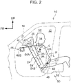
- FIG. 2 is a side view of a rear-facing occupant protection device 50 according to the present embodiment.
- an energy absorbing portion that absorbs energy at the time of a frontal collision by being deformed
- an energy absorbing member 54 in place of the energy absorbing member 38 (see FIG. 1 ), which differs from the rear-facing occupant protection device 18 (see FIG. 1 ) according to the first embodiment.
- the other configurations are substantially the same as those of the first embodiment. Therefore, the same reference numerals are added to components substantially the same as those of the first embodiment, and description thereof is omitted.
- the energy absorbing member 54 is arranged on the back surface 34B of the seatback pad 34A within a continuous range that includes: an upper region 54A including a position corresponding to the center of gravity Cx of the chest C of the seated occupant P; and a lower region 54B including a position corresponding to the center of gravity Lx of the waist L of the seated occupant P.
- This energy absorbing member 54 is held between the back surface 34B of the seatback pad 34A and the rear surface 24A of the inclined vertical wall portion 24.
- the energy absorbing member 54 is set such that a hardness in the lower region 54B is lower than a hardness in the upper region 54A.
- Such a configuration may be realized by applying materials having different material properties respectively to the upper region 54A and the lower region 54B, or by setting a density to be lower in the lower region 54B than in the upper region 54A.
- the hardness may be set to be lower in lower region 54B than in upper region 54A by changing a plate thickness and a pitch of the resin ribs in each of the lower region 54B and the upper region 54A.
- the energy absorbing member 54 is configured to be plastically deformed more greatly in the lower portion of the energy absorbing member 54 than in the upper portion of the energy absorbing member 54 when a pressing load of a predetermined value or more acts on a backrest surface 34X of the seatback 34 from the seated occupant P side.
- the amount of displacement becomes greater in the lower portion of the backrest surface 34X of the seatback 34 than in the upper portion of the backrest surface 34X of the seatback 34 when a pressing load of the predetermined value or more acts on the backrest surface 34X from the seated occupant P side.
- the energy absorbing member 54 is plastically deformed more greatly in the lower portion than in the upper portion. In other words, the energy absorbing member 54 is deformed in such a manner that the amount of displacement becomes greater in the lower portion of the backrest surface 34X of the seatback 34 than in the upper portion of the backrest surface 34X.
- the posture of the upper body of the seated occupant P in a vehicle side view changes so as to approach the vertical posture (so as to decrease the torso angle). For this reason, upward displacement of the seated occupant P along the backrest surface 34X of the seatback 34 is reduced, thereby improving the restraint performance of the seated occupant P, and kinetic energy of the seated occupant P at the time of a frontal collision can be thus absorbed by the energy absorbing member 54 in a preferable manner.
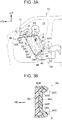
- FIG. 3A is a side view showing a rear-facing occupant protection device 60 according to the present embodiment
- FIG. 3B is an enlarged sectional view taken along line 3B-3B in FIG. 3A .
- the same reference numerals are added to substantially the same components as those of the first embodiment, and description thereof is omitted.
- a seatback pad 64A is provided in a front seat 62 of the present embodiment.
- a seatback 64 provided with the seatback pad 64A is mounted in a rear-facing state, as in the case of the seatback 34 (see FIG. 1 ) of the first embodiment.
- side support portions 64S bulging more frontward of the seatback than an intermediate portion in the seat width direction of the seatback pad 64A are provided on both sides in the seat width direction of the seatback pad 64A.
- an energy absorbing member 66 configuring an energy absorbing portion is provided.
- the energy absorbing member 66 is made of the same hard urethane foam as that of the energy absorbing member 38 (see FIG. 1 ) in the first embodiment. As shown in FIG.
- the energy absorbing member 66 is fixed to a back surface 64B of the seatback pad 64A, within a continuous range that includes: an upper region 66A (a region of the energy absorbing member 66 located above a two-dot chain line B3) including a position corresponding to the center of gravity Cx of the chest C of the seated occupant P; and a lower region 66B (a region of the energy absorbing member 66 located below the two-dot chain line B3) including a position corresponding to the center of gravity Lx of the waist L of the seated occupant P.
- This energy absorbing member 66 is held between the back surface 64B of the seatback pad 64A and the rear surface 24A of the inclined vertical wall portion 24.
- the energy absorbing member 66 includes a bulging portion 66S disposed along the back surface 64B of the seatback pad 64A and disposed inward of the side support portion 64S of the seatback pad 64A.
- a surface 66P of the energy absorbing member 66 closer to the seated occupant P is set into a shape, in a flat sectional shape of the surface 66P, corresponding to a shape extending from the back surface to the side surfaces closer to the back surface of the seating occupant P (a shape indicated by a two-dot chain line in FIG. 3B ).
- the same operation and effect as those of the above-described first embodiment can be obtained, and the holding performance of the seated occupant P by the seatback 64 can be improved by the energy absorbing member 66 under normal conditions.
- FIG. 4 is a side view showing a rear-facing occupant protection device 70 according to the present embodiment.
- the rear-facing occupant protection device of the present embodiment is different from the rear-facing occupant protection device 18 (see FIG. 1 ) according to the first embodiment in that an energy absorbing member 74 configuring an energy absorbing portion is provided, in place of the energy absorbing member 38 (see FIG. 1 ).
- the other configurations are substantially the same as those of the first embodiment. Therefore, the same reference numerals are added to substantially the same components as those of the first embodiment, and description thereof is omitted.
- the energy absorbing member 74 is formed of the same hard urethane foam as that of the energy absorbing member 38 (see FIG. 1 ) in the first embodiment.
- the energy absorbing member 74 is fixed to the back surface 34B of the seatback pad 34A, within a continuous range that includes: an upper region 74A (a region of the energy absorbing member 74 located above a two-dot chain line B4) including a position corresponding to the center of gravity Cx of the chest C of the seated occupant P; and a lower region 74B (a region of the energy absorbing member 74 located below the two-dot chain line B4) including a position corresponding to the center of gravity Lx of the waist L of the seated occupant P.
- the energy absorbing member 74 is held between the back surface 34B of the seatback pad 34A and the rear surface 24A of the inclined vertical wall portion 24.
- the energy absorbing member 74 is set such that a surface 74P closer to the seating occupant P is inclined downward of the seat toward the seating occupant P side, in a seat side view, and the thickness in the seat front-rear direction is gradually thicker from an upper end portion 74C in the seat height direction toward a lower end portion 74D in the seat height direction.
- the energy absorbing member 74 is set to be elastically deformed more greatly in a lower portion of the energy absorbing member 74 than in a upper portion of the energy absorbing member 74 when a pressing load of a predetermined value or more acts on the backrest surface 34X of the seatback 34 from the seated occupant P side.
- the energy absorbing member 74 is deformed such that the amount of displacement is greater in the lower portion than in the upper portion of the backrest surface 34X.
- FIG. 5 is a side view showing a rear-facing occupant protection device 80 according to the present embodiment.
- the same reference numerals are added to substantially the same components as those of the first embodiment, and description thereof is omitted.
- the seatback 84 includes a seatback frame 84F on the back surface 34B side of the seatback pad 34A.
- the seatback frame 84F is a frame-like member.
- the seatback pad 34A is held to the seatback frame 84F.
- a hinge portion 86H is provided to an upper end of the seatback frame 84F.
- the hinge portion 86H couples the upper end of the seatback frame 84F and a first vehicle-body-side component 88A provided on the inclined vertical wall portion 24 so as to support and allow the seatback frame 84F to be turnable about the axis in the seat width direction.
- the seatback frame 84F indicated by a two-dot chain line shows a state in which the seatback frame 84F is turned in the vehicle forward direction by a predetermined angle from a position of the seatback frame 84F indicated by a solid line.
- the first vehicle-body-side component 88A is configured by a reinforcement fixed to the upper end of the inclined vertical wall portion 24.
- Springs 86S as an elastic member are provided to a lower end of the seatback frame 84F.
- the springs 86S are compression coil springs in the present embodiment, and are provided in pair on the right and left of the seat width direction, for example.
- the pair of right and left springs 86S are interposed between the lower end of the seatback frame 84F and a second vehicle-body-side component 88B provided below the first vehicle-body-side component 88A, and urges the lower end of the seatback frame 84F toward the seated occupant P side.
- the second vehicle-body-side component 88B is a part of the lower end of the inclined vertical wall portion 24, for an example.
- a surface of the second vehicle-body-side component 88B located on the vehicle front side may be reinforced by a reinforcing member.
- the spring 86S configures an energy absorbing portion. That is, the springs 86S are disposed between the back surface 34B of the seatback pad 34A of the seatback 84 and the rear surface 24A of the inclined vertical wall portion 24, and becomes deformed to absorb energy at the time of a frontal collision.
- the seatback frame 84F turns about the axis of the hinge portion 86H in the seat width direction while the springs 86S contract. At this time, deformation of the spring 86S absorbs kinetic energy of the seated occupant P at the time of the frontal collision.
- the amount of displacement is greater in the lower portion of the seatback frame 84F than in the upper portion thereof, and thus the posture of the upper body of the seated occupant P in a vehicle side view changes so as to approach the vertical posture; therefore, upward displacement of the seated occupant P along the backrest surface 34X of the seatback 84 is reduced.
- this configuration also contributes to improvement of the ride down effect.
- FIG. 6A is a side view showing in-situ major parts of a rear-facing occupant protection device 90 according to the present embodiment
- FIG. 6B is an enlarged cross-sectional view taken along line 6B-6B of FIG. 6A
- FIG. 7 is a perspective view showing the major parts of the rear-facing occupant protection device 90 according to the sixth embodiment.
- the same reference numerals are added to substantially the same components as those of the first embodiment, and description thereof is omitted.
- a seatback 94 of a vehicle seat 92 (hereinafter referred to simply as a "seat 92") is mounted in a rear-facing state in the vehicle 10.
- FIGS. 6A, 6B and FIG. 7 show only skeleton parts of the seat 92, and illustration of the pad and others is omitted.
- the seat 92 is a front seat, but the seat 92 may be a second seat (seat located in a second row) of seats in three rows.
- the rear-facing occupant protection device 90 of the present embodiment has a reclining mechanism 98 capable of adjusting a tilt angle of the seatback 94.
- a reclining mechanism having a known configuration is adopted as this reclining mechanism 98; therefore, detailed description is omitted.
- the seatback 94 includes a pair of right and left side frames 94F that extend in the seatback height direction on both sides of the seatback 94. Respective upper ends of the right and left side frames 94F in pair are coupled to each other by an upper frame 94U formed in a reverse U-shape in a seatback front view. Respective lower portions of the right and left side frames 94F are coupled to each other by a reclining rod 98S. Then, the seatback 94 is configured to be able to recline about the axis of the reclining rod 98S.
- the movable body 94M includes: a shaft 94X configuring an upper end of the movable body 94M and extended in the seat width direction; and a plate-like seatback panel portion 94A extended from the shaft 94X toward the seat lower side.
- the shaft 94X is turnably suspended across the pair of right and left side frames 94F, and the seatback panel portion 94A supports the back of the seated occupant P (see FIG. 6A ).
- a plate-like coupling member 94B is disposed on the opposite side of the seatback panel portion 94A from the seated occupant P. As shown in FIG. 6B , the coupling member 94B couples respective lower portions of the pair of the right and left side frames 94F in the seat width direction.
- springs 94S as an elastic member are interposed between the lower end of the seatback panel portion 94A and the coupling member 94B.
- the springs 94S are compression coil springs in the present embodiment, and are provided, for example, in pair on the right and left sides in the seat width direction.
- One side of the springs 94S is fixed to the lower end of the seatback panel 94A, the other side thereof is fixed to the coupling members 94B, and the lower end of the seatback panel 94A is urged toward the seated occupant P (see FIG. 6A ) side.
- the movable body 94M turns about the axis in the seat width direction while the springs 94S contract.
- deformation of the springs 94S absorbs kinetic energy of the seated occupant P at the time of the frontal collision.
- the amount of displacement is greater in the lower portion of the seatback panel portion 94A than in the upper portion thereof, and the posture of the upper body of the seated occupant P in a vehicle side view changes so as to approach the vertical posture.
- the rear-facing occupant protection device 90 since the rear-facing occupant protection device 90 has the reclining mechanism 98, when the rear-facing seated occupant P inertially moves toward the seatback 94 side at the time of a frontal collision, there is a possibility that the seatback 94 may slightly tilt in a reclining direction. If the seatback 94 tilts in the reclining direction, this is disadvantageous in reducing the upward displacement of the seated occupant P.
- the seatback panel portion 94A turns about the axis in the seat width direction while the springs 94S contract; therefore, it is possible to suppress the upper body of the seated occupant P in a vehicle side view from tilting toward the front lower side of the vehicle. Therefore, even if the reclining mechanism 98 is provided, upward displacement of the seated occupant P at the time of a frontal collision is reduced.
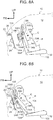
- FIG. 8A is a side view showing a rear-facing occupant protection device 100 according to the present embodiment
- FIG. 8B is a side view showing a state of the rear facing occupant protection device 100 at the time of a frontal collision.
- components inside the front seat 102 are simply illustrated in a sectional view showing a state in which an intermediate portion of the front seat 102 in the seat width direction is cut along the seat height direction, as viewed from the seat side.
- the same reference numerals are added to substantially the same components as those of the first embodiment, and description thereof is omitted.
- the front seat 102 of the present embodiment shown in FIG. 8A includes a pair of right and left side frames 104F that extend in the seatback height direction on both sides of the seatback 104. Upper ends of the pair of right and left side frames 104F are coupled to each other in the seat width direction by an upper frame 104A.
- a headrest stay 105A is attached to the upper frame 104A, and the seatback 104 and the headrest 105 are coupled to each other in the seat height direction by the headrest stay 105A.
- a holding pipe 104B that couples the pair of right and left side frames 104F in the seat width direction is disposed below the upper frame 104A in the height direction of the seatback.
- the holding pipe 104B is disposed in an upper portion of the seatback 104.
- the upper frame 104A and the holding pipe 104B each have a rectangular cross-sectional shape in a side view of the seat.
- An energy absorbing member 106 configuring an energy absorbing portion is disposed on rear surfaces of the upper frame 104A and the holding pipe 104B.
- An upper portion of the energy absorbing member 106 is fixed to the upper frame 104A by an adhesive, and a lower portion of the energy absorbing member 106 is fixed to the holding pipe 104B by an adhesive.
- the energy absorbing member 106 overlaps both the upper frame 104A and the holding pipe 104B from the seat back-surface side, and the energy absorbing member 106 is disposed on an upper portion of the back surface 34B of the seatback pad 34A of the seatback 104 via the upper frame 104A and the holding pipe 104B.
- the energy absorbing member 106 is set in a chest corresponding region including the position corresponding to the center of gravity Cx of the chest C of the seated occupant P.
- this energy absorbing member 106 is made of an aluminum alloy, and is formed in a structure (e.g. a honeycomb structure) including a porous material that absorbs energy at the time of a frontal collision as the energy absorbing member 106 by plastically deformation.
- a portion of the seatback 104 to which the energy absorbing member 106 is provided is a protrusion 108 that protrudes toward the rear side in the front-rear direction of the seatback.
- a bracket 112 as a reinforcing member for reinforcing a part pressed by the energy absorbing member 106 at the time of a frontal collision is fixed to a vehicle front portion of the inclined vertical wall portion 24 of the front body panel 20 by welding or the like.
- the bracket 112 is extended along the vehicle width direction and is set at a position corresponding to a part where the energy absorbing member 106 presses the inclined vertical wall portion 24 when the seatback 104 moves toward the vehicle front side while tilting toward the vehicle front side by the reclining mechanism at the time of a frontal collision (see FIG. 8B ).
- the bracket 112 is formed in a substantially hat-like shape having an opening directed toward the vehicle rear side in a vehicle side view. Upper and lower flange portions of the bracket 112 are joined to the inclined vertical wall portion 24 so as to form a closed cross-sectional portion extending along the vehicle width direction.
- the seatback 104 moves toward the vehicle front side while tilting toward the front side of the seat, and then, the protrusion 108 abuts against the rear surface 24A of the inclined vertical wall portion 24 via the lining material 110. Then, plastic deformation of the energy absorbing member 106 absorbs kinetic energy of the seated occupant P at the time of the frontal collision. As a result, impact on the chest C of the seated occupant P is effectively reduced. Further, since the energy absorbing member 106 is provided to the seatback 104, it is possible to cope with an oblique collision without increasing the width of the energy absorbing member 106 for the oblique collision.
- FIG. 9 is a side view showing the rear-facing occupant protection device 120 according to the present embodiment at the time of a frontal collision.
- components inside a front seat 122 are simply illustrated in a sectional view showing a state in which an intermediate portion of the front seat 122 in the seat width direction is cut along the seat height direction, as viewed from the seat side.
- the posture of the seatback 124 of the front seat 122 in a state before a frontal collision is the same as the posture of the seatback 104 shown in FIG. 8A , as an example.
- the same reference numerals are added to substantially the same components as those of the first and seventh embodiments, and description thereof is omitted.
- the seatback 124 is not provided with the energy absorbing member 106 (see FIG. 8A and 8B ) in the seventh embodiment, which differs from the seatback 104 of the seventh embodiment.
- the seatback 124 includes a protrusion 126 that protrudes toward the rear side in the front-rear direction of the seatback, in an upper portion (a chest corresponding region including the position corresponding to the center of gravity Cx of the chest C of the seated occupant P) of the seatback 124 where the upper frame 104A and the holding pipe 104B are disposed.
- the inner side of the vehicle cabin 12 of the front body panel 20 is covered with a lining material 130.
- a portion of the lining material 130 located on the vehicle rear side of the inclined vertical wall portion 24 of the front body panel 20 is formed in a substantially hat-like shape having an opening facing toward the vehicle front side in a vehicle side view, and an intermediate portion of the lining material 130 in the vehicle height direction is set as a protrusion 132 that protrudes toward the vehicle rear side.
- the protrusion 132 is set at a position where the protrusion 132 is pressed by the upper frame 104A and the holding pipe 104B at the time of a frontal collision (in a state shown in FIG. 9 ).
- An energy absorbing member 134 configuring an energy absorbing portion is disposed between the inclined vertical wall portion 24 of the front body panel 20 and the protrusion 132 of the lining material 130.
- the energy absorbing member 134 is configured substantially the same as the energy absorbing member 106 in the seventh embodiment, and is a member that absorbs energy at the time of a frontal collision by being plastically deformed.
- the energy absorbing member 134 is fixed by an adhesive to a portion of the rear surface 24A of the inclined vertical wall portion 24 of the front body panel 20, the portion pressed being pressed by the upper frame 104A and the holding pipe 104B at the time of a frontal collision.
- the protrusion 132 and the energy absorbing member 134 extend not only through the same range in the vehicle width direction as that of the seatback 124 but also to predetermined positions on both sides of the seatback 124.
- a bracket 112 for reinforcing the inclined vertical wall portion 24 is fixed on the opposite side of the inclined vertical wall portion 24 from the energy absorbing member 134.
- the bracket 112 is disposed in the same range in the vehicle width direction as that of the energy absorbing member 134.
- the seatback 124 moves toward the vehicle front side, so that the protrusion 126 of the seatback 124 abuts against the protrusion 132 of the lining 130, as shown in FIG 9 .
- a load is input from the protrusion 126 of the seatback 124 to the energy absorbing member 134 via the protrusion 132 of the lining material 130, and the energy absorbing member 134 is plastically deformed, thereby absorbing kinetic energy of the seated occupant P at a frontal collision.
- an impact on the chest C of the seated occupant P is effectively reduced.
- the energy absorbing member 134 is disposed on the front body panel 20 side, whereby the mass of the front seat 122 can be reduced. Therefore, an input load from the front seat 122 to the vehicle body side can be reduced.
- each of the front seats 30, 52, 62, 72, 82, 102, 122, and the seat 92 is each mounted in the vehicle 10 in a rear-facing state; however, the vehicle seat including the front seat may be mounted in an automobile (vehicle) in such a manner that the vehicle seat is configured to be turnable about the axis extending in the vehicle height direction so as to face rearward.
- the energy absorbing members 54, 66, 74 are fixed to the seatback pads 34A, 64A by being integrally molded (more specifically, integrally foam-molded) with the seatback pads 34A, 64A, for example.
- the energy absorbing member and the seatback pad may be separately formed, and thereafter, they both may be joined to each other with an adhesive or the like.
- the energy absorbing members 38, 54, 66, 74 are formed "continuously" in the height direction of the seatback, but the description "a range that includes” set forth in claim 2 is not limited to a single range.
- the energy absorbing member may include: an upper region including the position corresponding to the center of gravity (Cx) of the chest (C) of the seated occupant (P); and a lower region including the position corresponding to the center of gravity (Lx) of the waist (L) of the seated occupant (P), the upper region and the lower region being divided in the height direction.
- the springs 86S and 94S as elastic members are compression coil springs.
- the elastic member may be configured by springs other than the compression coil springs, such as springs formed by stacking a plurality of plate springs, or may be a member configured to include springs and rubber.
- the rear-facing occupant protection device 90 includes the reclining mechanism 98, but the rear-facing passenger protection device may be a device including a configuration excluding the reclining mechanism 98 in the configuration of the sixth embodiment.
- the seat belt unit is also applied to these embodiments.
- the present invention is not limited to the above, and it is needless to mention that other than the above, the present invention can be variously modified and carried out without deviating from the invention.
Landscapes
- Engineering & Computer Science (AREA)
- Mechanical Engineering (AREA)
- Aviation & Aerospace Engineering (AREA)
- Transportation (AREA)
- Manufacturing & Machinery (AREA)
- Seats For Vehicles (AREA)
Abstract
Description
- The present invention relates to a rear-facing occupant protection device.
- Techniques regarding vehicle seat devices are known (see Japanese Patent Application Publication No.
2017-149331 2017-149351 2018-52347 2017-210173 JP 2017-149331 A - However, there is room for improvement of sufficient absorption of kinetic energy caused when the rear-facing seated occupant inertially moves toward the front side of the vehicle at the time of a frontal collision.
- The present invention provides a rear-facing occupant protection device capable of improving absorption of kinetic energy caused when a rear-facing seated occupant inertially moves toward the front side of the vehicle at the time of a frontal collision.
- A first aspect of the invention provides a rear-facing occupant protection device applied to a vehicle in which a seatback of a front seat is mounted in a rear-facing state in which a back surface of the seatback faces a vehicle-body-side vertical wall portion disposed at a front end of a vehicle cabin, or mounted such that the seat back is capable of taking the rear-facing state, the rear-facing occupant protection device. The rear-facing occupant protection device includes: an energy absorbing portion disposed on at least one of a back surface of a seatback pad of the seatback and a rear surface of the vehicle-body-side vertical wall portion, the energy absorbing portion being configured to be deformed so as to absorb energy at a time of a frontal collision of the vehicle. A concept that "an energy absorbing portion is disposed on at least one" in the description that "an energy absorbing portion configured to be deformed so as to absorb energy at the time of a frontal collision is disposed on at least one" may include not only the case in which the energy absorbing portion is directly disposed on at least one, but also the case in which the energy absorbing portion is disposed via an intervention on at least one".
- According to the above configuration, at the time of a frontal collision, the rear-facing seated occupant inertially moves toward the vehicle front side, that is, toward the seatback side (seat rear side), and the energy absorbing portion is deformed due to this inertial movement, and thus kinetic energy of the seated occupant at the time of a frontal collision is absorbed.
- In the first aspect, the energy absorbing portion may include an energy absorbing member configured to absorb the energy at the time of the frontal collision by being plastically deformed, and the energy absorbing member is disposed on the back surface of the seatback pad within a range that includes an upper region including a position corresponding to a center of gravity of a chest of a seated occupant, and a lower region including a position corresponding to a center of gravity of a waist of the seated occupant.
- According to the above configuration, at the time of a frontal collision, the back of the chest of the seated occupant is supported by the rear surface of the vehicle-side vertical wall via the seatback pad and the upper region of the energy absorbing member, and the waist of the seated occupant is supported by the rear surface of the vehicle-body-side vertical wall via the seatback pad and the lower region of the energy absorbing member. Then, the region including the upper region and the lower region of the energy absorbing member is plastically deformed due to the inertial movement of the seated occupant, whereby kinetic energy of the seated occupant at the time of a frontal collision is absorbed.
- In the first aspect, the energy absorbing portion may be configured to be deformed such that an amount of displacement is greater in a lower portion of a backrest surface of the seatback than in an upper portion of the backrest surface of the seatback when a pressing load of a predetermined value or more is applied to the backrest surface of the seatback from an seated occupant.
- According to the above-described configuration, when the rear-facing seated occupant inertially moves toward the seatback side at the time of a frontal collision and a pressing load of a predetermined value or more is applied to the backrest surface of the seatback from the seated occupant side, the energy absorbing portion is deformed such that the amount of displacement becomes greater in the lower portion of the backrest surface than in the upper portion of the backrest surface. With this configuration, since the posture of the upper body of the seated occupant in the vehicle side view changes so as to approach the vertical posture, upward displacement of the seated occupant along the backrest surface of the seatback is reduced, and the restraint performance of the seated occupant is thus improved.
- In the first aspect, the energy absorbing portion may be configured to be deformed such that an amount of displacement is greater in a lower portion of a backrest surface of the seatback than in an upper portion of the backrest surface of the seatback when a pressing load of a predetermined value or more is applied to the backrest surface of the seatback from the seated occupant, and the energy absorbing member may be configured to be plastically deformed such that an amount of displacement is greater in a lower portion of the energy absorbing member than in an upper portion of the energy absorbing member when a pressing load of a predetermined value or more is applied to the backrest surface of the seatback from the seated occupant.
- According to the above-described configuration, when the rear-facing seated occupant inertially moves toward the seatback side at the time of a frontal collision and a pressing load of a predetermined value or more is applied to the backrest surface of the seatback from the seated occupant side, the energy absorbing portion is plastically deformed more greatly in the lower portion of the back surface than in the upper portion of the back surface. With this configuration, while improving the restraint performance of the seated occupant, it is possible to preferably absorb kinetic energy of the seated occupant at the time of a frontal collision by the energy absorbing member.
- In the above configuration, a hardness in the lower region of the energy absorbing member may be lower than a hardness in the upper region of the energy absorbing member.
- According to the above configuration, even with such a simple configuration, the lower region of the energy absorbing member can be plastically deformed more greatly than the upper region of the energy absorbing member at the time of a frontal collision.
- In the above configuration, the energy absorbing member may be set such that a surface of the energy absorbing member located on a seating occupant side in a seat side view is inclined toward a seat lower side to the seated occupant side, and a thickness in a seat front-rear direction of the energy absorbing member may be gradually increased from an upper end portion in a seat height direction of the energy absorbing member toward a lower end portion in the seat height direction of the energy absorbing member.
- According to the above configuration, even with such a simple configuration, the amount of deformation can be set greater in the lower portion of the energy absorbing member than in the upper portion of the energy absorbing member at the time of a frontal collision.
- In the first aspect, side support portions bulging more frontward of the seatback than an intermediate portion of the seatback pad in a seat width direction may be provided on both sides of the seatback pad in the seat width direction, the energy absorbing member may include a bulging portion disposed along a back surface of the seatback pad and disposed inward of the side support portion, and a surface of the energy absorbing member closer to the seated occupant may be set into a shape, in a flat sectional shape of the surface, corresponding to a shape extending from a back surface to side surfaces near the back surface of the seated occupant. The description that "toward a seatback front side" may be considered as a front side in the front-rear direction of the seatback (seat front-rear direction).
- According to the above configuration, kinetic energy of the seated occupant is absorbed by the energy absorbing member at the time of a frontal collision, and holding performance of the seated occupant by the seatback is improved by the energy absorbing member at the normal time.
- In the above configuration, the energy absorbing member may be integrally molded with the seatback pad.
- According to the above configuration, manufacturing is facilitated and cost reduction can be achieved.
- In the first aspect, the rear-facing occupant protection device may further include: a pair of side frames that extend in a seatback height direction at respective ends of the seatback in a vehicle width direction; an upper frame coupling upper ends of the pair of side frames to each other; and a holding pipe that couples the pair of side frames and is disposed below the upper frame in the seatback height direction. The energy absorbing portion may include an energy absorbing member that is plastically deformed so as to absorb the energy at the time of the frontal collision, the energy absorbing member may overlap both the upper frame and the holding pipe from a seat back-surface side in a direction orthogonal to the surface of the seatback, and a reinforcing member that reinforces a part pressed by the energy absorbing member at the time of the frontal collision may be fixed to the vehicle-body-side vertical wall portion.
- According to the above configuration, when the rear-facing seated occupant inertially moves toward the seatback side at the time of a frontal collision, the energy absorbing member moves together with the upper frame and the holding pipe toward the vehicle front side, and thus presses the vehicle-body-side vertical wall portion. Here, a part of the vehicle-body-side vertical wall portion pressed by the energy absorbing member is reinforced by the reinforcing member. Accordingly, at the time of a frontal collision, the energy absorbing member is plastically deformed in a preferable manner so as to absorb kinetic energy of the seated occupant at the time of the frontal collision. As a result, an impact applied on the chest of the seated occupant is effectively reduced.
- In the first aspect, the rear-facing occupant protection device may further include: a pair of side frames that extend in a seatback height direction on respective sides of the seatback; an upper frame coupling respective upper ends of the pair of side frames to each other; and a holding pipe that couples the pair of side frames and is disposed below the upper frame in the seatback height direction. The energy absorbing portion may include an energy absorbing member configured to be plastically deformed so as to absorb the energy at the time of the frontal collision. The energy absorbing member may be held to a part pressed by the upper frame and the holding pipe at the time of the frontal collision on a rear surface of the vehicle-body-side vertical wall portion in a vehicle front-rear direction, and a reinforcing member that reinforces the vehicle-body-side vertical wall portion may be fixed on an opposite side of the vehicle-body-side vertical wall portion from the energy absorbing member.
- According to the above configuration, when the rear-facing seated occupant inertially moves toward the seatback side at the time of a frontal collision, the upper frame and the holding pipe move toward the vehicle front side, and press the rear surface of the vehicle-body-side vertical wall portion. Here, the energy absorbing member is held at a part of the rear surface of the vehicle-body-side vertical wall portion, the part pressed by the upper frame and the holding pipe at the time of a frontal collision, and the reinforcing member for reinforcing the vehicle-body-side vertical wall portion is fixed on the opposite side of the vehicle-body-side vertical wall portion from the energy absorbing member. Accordingly, at the time of a frontal collision, the energy absorbing member is plastically deformed in a preferable manner so as to absorb kinetic energy of the seated occupant at the time of the frontal collision. As a result, an impact applied on the chest of the seated occupant is effectively mitigated.
- In the first aspect, the energy absorbing portion may be configured to be deformed such that an amount of displacement is greater in a lower portion of a backrest surface of the seatback than in an upper portion of the backrest surface of the seatback when a pressing load of a predetermined value or more is applied to the backrest surface of the seatback from an seated occupant, and the rear-facing occupant protection device may further includes: a seatback frame to which the seatback pad is held; and a hinge portion couples an upper end of the seatback frame and a first vehicle-body-side component provided on the vehicle-body-side vertical wall portion so as to turnably support the seatback frame about an axis in a seat width direction. The energy absorbing portion may include an elastic member that is interposed between a lower end of the seatback frame and a second vehicle-body-side component so as to urge the lower end of the seatback frame toward the seated occupant, the second vehicle-body-side component being provided below the first vehicle-body-side component.
- According to the above configuration, when the rear-facing seated occupant inertially moves toward the seatback side at the time of a frontal collision, the seatback frame turns about the axis of the hinge portion in the seat width direction while an elastic member contracts. At this time, deformation of the elastic member absorbs the kinetic energy of the seated occupant at the time of the frontal collision. Further, at this time, the amount of displacement is greater in the lower portion of the seatback frame than in the upper portion thereof, and the posture of the upper body of the seated occupant in a vehicle side view changes so as to approach the vertical posture; therefore, upward displacement of the seated occupant along the back surface of the seatback is reduced.
- In the first aspect, the rear-facing occupant protection device may further include: a three-point seat belt unit applied to the vehicle in which the seatback is mounted in the rear-facing state, the three-point seat belt unit including a retractor configured to wind up a seat belt, the three-point seat belt unit being configured to restrain an upper body of an occupant seated in the rear-facing front seat by a shoulder belt portion configuring a part of the seat belt, and restrain a waist of the occupant by a lap belt portion configuring another part of the seat belt.
- According to the above configuration, when the retractor fixed to the vehicle body in the front part of the vehicle winds up the seat belt at the time of a frontal collision, the upper body of the rear-facing seated occupant is restrained by the shoulder belt portion and the waist of the seated occupant is restrained by the lap belt portion at the same time. Therefore, the rear-facing seated occupant can be effectively restrained by the three-point seat belt unit at the time of the frontal collision.
- A second aspect of the invention provides a rear-facing occupant protection device applied to a vehicle in which a seatback of a vehicle seat is mounted in a rear-facing state or mounted and configured to face rearward. The rear-facing occupant protection device includes: a pair of side frames extended in a height direction of the seatback on respective ends of the seatback in a vehicle width direction; a movable body having an upper end supported to upper portions of the pair of side frames so as to be turnable about an axis in a seat width direction, the movable body including a seatback panel portion supporting a back of a seated occupant; a coupling member disposed on an opposite side of the seatback panel portion from the seated occupant so as to couple the pair of side frames in the seat width direction; and an elastic member interposed between a lower end of the seatback panel portion and the coupling member so as to urge the lower end of the seatback panel portion toward the seated occupant.
- According to the above configuration, when the rear-facing seated occupant inertially moves toward the seatback side at the time of a frontal collision, the movable body turns about the axis in the seat width direction while the elastic member contracts. At this time, deformation of the elastic member absorbs kinetic energy of the seated occupant at the time of the frontal collision. In addition, at this time, the amount of displacement of the seatback panel portion is greater in the lower portion of the seatback panel portion than in the upper portion of the seatback panel portion, and the posture of the upper body of the seated occupant in a vehicle side view changes so as to approach the vertical posture. Therefore, upward displacement of the seated occupant is reduced, and restraint performance of the seated occupant is improved.
- In the second aspect, the rear-facing occupant protection device may further include a reclining mechanism configured to adjust a tilt angle of the seatback.
- According to the above configuration, since the reclining mechanism is provided, there is a possibility that the rear-facing seated occupant may tilt slightly in the direction in which the seatback is reclined when the rear-facing seated occupant inertially moves toward the seatback side at the time of a frontal collision. If the seated occupant tilts in the direction where the seatback is reclined, this is disadvantageous in reducing the upward displacement of the seated occupant. However, in the present invention, when the rear-facing seat occupant inertially moves toward the seatback side at the time of a frontal collision, the seatback panel portion turns about the axis in the seat width direction while the elastic member contracts; therefore, it is possible to suppress the upper body of the seated occupant in a vehicle side view from tilting toward the front lower side of the vehicle. Accordingly, even if the reclining mechanism is provided, upward displacement of the seated occupant at the time of a frontal collision is reduced.
- As described above, according to the rear-facing occupant protection device of the present invention, it is possible to exert an excellent effect to sufficiently absorb kinetic energy caused when a rear-facing seated occupant inertially moves toward the vehicle front side at the time of a frontal collision.
- Features, advantages, and technical and industrial significance of exemplary embodiments of the invention will be described below with reference to the accompanying drawings, in which like numerals denote like elements, and wherein:
-
FIG. 1 is a side view showing a rear-facing occupant protection device according to a first embodiment; -
FIG. 2 is a side view showing a rear-facing occupant protection device according to a second embodiment; -
FIG. 3A is a side view showing a rear-facing occupant protection device according to a third embodiment; -
FIG. 3B is an enlarged sectional view taken alongline 3B-3B inFIG. 3A ; -
FIG. 4 is a side view showing a rear-facing occupant protection device according to a fourth embodiment; -
FIG. 5 is a side view showing a rear-facing occupant protection device according to a fifth embodiment; -
FIG. 6A is a side view showing in-situ major parts of a rear-facing occupant protection device according to a sixth embodiment; -
FIG. 6B is an enlarged sectional view taken alongline 6B-6B ofFIG. 6A ; -
FIG. 7 is a perspective view showing major parts of the rear-facing occupant protection device according to the sixth embodiment; -
FIG. 8A is a side view showing a rear-facing occupant protection device according to a seventh embodiment; -
FIG. 8B is a side view showing a state of the rear-facing occupant protection device according to the seventh embodiment at the time of a frontal collision; and -
FIG. 9 is a side view showing a state of a rear-facing occupant protection device according to an eighth embodiment at the time of a frontal collision. - A rear-facing occupant protection device according to the first embodiment of the present invention will be described with reference to
FIG. 1. FIG. 1 is a side view showing a rear-facingoccupant protection device 18 according to the present embodiment. In each of the drawings, an arrow FR indicates a front side of the vehicle, and an arrow UP indicates an upper side of the vehicle. - As shown in
FIG. 1 , afront body panel 20 is disposed on the front end side of avehicle cabin 12 of a vehicle (automobile) 10, and thefront body panel 20 extends along a width direction of the vehicle. Thefront body panel 20 includes atop wall portion 22 extending from a vicinity of a lower end of a windshield (not shown) disposed between a pair of right and leftfront pillars 14 toward a rear side of the vehicle along a vehicle front-rear direction. Further, thefront body panel 20 is provided with an inclinedvertical wall portion 24 as a vehicle-body-side vertical wall portion extending from a rear end of thetop wall portion 22 toward a lower rear side of the vehicle. - A rear-facing
front seat 30 is mounted rearward of vehicle of thefront body panel 20 in a front part of thevehicle cabin 12. Thefront seat 30 has aseat cushion 32 for supporting the buttocks and thighs of a seated occupant P, and aseatback 34 coupled to an end of theseat cushion 32 located on the rear side in a seat front-rear direction so as to support the back of the seated occupant P, and aheadrest 36 coupled to an upper end of theseatback 34 so as to support the head of the seated occupant P. - That is, the
vehicle 10 in the present embodiment is an automobile (vehicle) in which theseatback 34 of thefront seat 30 is mounted so as to face rearward with the back surface of theseatback 34 facing the inclinedvertical wall portion 24 of thefront body panel 20. - In
FIG. 1 , a dummy P for a collision test is seated in thefront seat 30 in place of an actual occupant. This dummy P is an AM50 (50 percentile of American adult males). Hereinafter, for easiness of description, the dummy P seated in thefront seat 30 in a rear-facing state is referred to as a "seated occupant P". - The
seatback 34 includes aseatback pad 34A configuring an elastically deformable cushion portion, and a seat skin (not shown) covering theseatback pad 34A. Theseatback pad 34A is formed of foam, such as urethane foam. - An
energy absorbing member 38 configuring an energy absorbing portion is disposed on aback surface 34B of theseatback pad 34A of theseatback 34. Thisenergy absorbing member 38 is held between theback surface 34B of theseatback pad 34A and arear surface 24A of the inclined vertical wall portion 24 (an element also understood as a "body supporting surface"). Theenergy absorbing member 38 is configured to be elastically deformed so as to absorb energy at the time of a frontal collision. Theenergy absorbing member 38 is fixed to theback surface 34B of theseatback pad 34A, within a continuous range that includes: anupper region 38A (a region of theenergy absorbing member 38 located above a two-dot chain line B1) including a position corresponding to a center of gravity Cx of a chest C of the seated occupant P; and alower region 38B (a region of theenergy absorbing member 38 located below the two-dot chain line B1) including a position corresponding to the center of gravity Lx of the waist L of the seated occupant P. More simply, thelower region 38B may be set as a region in theenergy absorbing member 38, the region being located lower than the central portion of theenergy absorbing member 38 in the seat height direction of theenergy absorbing member 38. - The
energy absorbing member 38 is formed of, for example, a hard urethane foam, and is fixed to theseatback pad 34A by being integrally molded (more specifically, integrally foam-molded) with theseatback pad 34A. Theenergy absorbing member 38 may be formed of expanded polypropylene (EPP). In addition, as another modification, theenergy absorbing member 38 may be configured by resin ribs (for example, resin ribs in grid). - Further, a three-point
seat belt unit 40 is provided so as to correspond to the above-describedfront seat 30. The three-pointseat belt unit 40 includes aseat belt 42 for restraining the occupant. One end of theseat belt 42 is attached, via ananchor plate 44, to a side portion (side surface portion shown inFIG. 1 ) of theseat cushion 32 located on one side in the vehicle width direction, and the other end of theseat belt 42 is locked to aspool 46S of aretractor 46. Further, abuckle unit 48 is provided upright on a side portion (side surface portion on the back side in the drawing ofFIG. 1 ) of theseat cushion 32 on the other side in the vehicle width direction. Atongue plate 49 supported with being inserted into an intermediate portion of theseat belt 42 is configured to be engageable with thebuckle unit 48. - As described above, in a state where the
seat belt 42 is fastened to the seated occupant P (seeFIG. 1 ), the three-pointseat belt unit 40 restrains the upper body of the seated occupant P by ashoulder belt portion 42X configuring a part of theseat belt 42, and restrains a waist L of the seated occupant P by alap belt portion 42Y configuring another part of theseat belt 42. - The
retractor 46 of the three-pointseat belt unit 40 is fixed to the vehicle body in the front part of the vehicle. As an example, theretractor 46 is disposed inside thefront body panel 20 and fixed to a vehicle body frame (not shown), and theseat belt 42 extended from theretractor 46 is inserted through a not-shown belt through-hole of the inclinedvertical wall portion 24 to be arranged in thevehicle cabin 12. Theretractor 46 is configured to wind up theseat belt 42 by thespool 46S. The axial direction of thespool 46S is disposed along the vehicle width direction. Theretractor 46 is always urged in a direction in which thespool 46S winds up theseat belt 42 by a not-shown urging mechanism. The three-pointseat belt unit 40 includes a not-shown pre-tensioner. The pre-tensioner operates so as to rotate thespool 46S in a direction where theseat belt 42 is wound up when a not-shown frontal collision detection unit or frontal collision prediction unit detects or predicts a frontal collision of thevehicle 10. - Operation and effects of the above embodiment will be described hereinafter.
- In the present embodiment, at the time of a frontal collision, the rear-facing seated occupant P inertially moves toward the vehicle front side, that is, toward the
seatback 34 side (seat rear side). At this time, a rear part of the chest C of the seated occupant P is supported on therear surface 24A of the inclinedvertical wall portion 24 via theseatback pad 34A and theupper region 38A of theenergy absorbing member 38. In addition, the waist L of the seated occupant P is supported on therear surface 24A of the inclinedvertical wall portion 24 via theseatback pad 34A and thelower region 38B of theenergy absorbing member 38. The entire region of theenergy absorbing member 38 including theupper region 38A and thelower region 38B is plastically deformed due to inertial movement of the seated occupant P, whereby kinetic energy of the seated occupant P at the time of a frontal collision is absorbed. - As described above, according to the rear-facing
occupant protection device 18 of the present embodiment, it is possible to sufficiently absorb kinetic energy caused when the rear-facing seated occupant P inertially moves toward the vehicle front side at the time of a frontal collision. - In the present embodiment, the
energy absorbing member 38 is disposed on theback surface 34B of theseatback pad 34A within a continuous range including the position corresponding to the center of gravity Cx of the chest C of the seated occupant P and the position corresponding to the center of gravity Lx of the waist L of the seated occupant P. Therefore, at the time of a frontal collision, a load from theseatback pad 34A can be received in a wide range, and for example, deformation of the chest C of the seated occupant P at the time of the frontal collision can be effectively reduced. - In addition, in the present embodiment, since the
energy absorbing member 38 is integrally molded with theseatback pad 34A, which facilities manufacturing and can reduce the cost. - Moreover, in the present embodiment, at the time of a frontal collision, when the
retractor 46 fixed to the vehicle body in the front part of the vehicle winds up theseat belt 42, the upper body of the rear-facing seated occupant P is restrained by theshoulder belt portion 42X and the waist L of the seated occupant P is restrained by thelap belt portion 42Y. Therefore, the rear-facing seat occupant P can be effectively restrained by the three-pointseat belt unit 40 at the time of a frontal collision. - Next, a rear-facing occupant protection device according to the second embodiment of the present invention will be described with reference to
FIG. 2. FIG. 2 is a side view of a rear-facingoccupant protection device 50 according to the present embodiment. In the present embodiment, as a member constituting an energy absorbing portion (hereinafter, simply referred to as an "energy absorbing portion") that absorbs energy at the time of a frontal collision by being deformed, provided is anenergy absorbing member 54 in place of the energy absorbing member 38 (seeFIG. 1 ), which differs from the rear-facing occupant protection device 18 (seeFIG. 1 ) according to the first embodiment. The other configurations are substantially the same as those of the first embodiment. Therefore, the same reference numerals are added to components substantially the same as those of the first embodiment, and description thereof is omitted. - In the
front seat 52, theenergy absorbing member 54 is arranged on theback surface 34B of theseatback pad 34A within a continuous range that includes: anupper region 54A including a position corresponding to the center of gravity Cx of the chest C of the seated occupant P; and alower region 54B including a position corresponding to the center of gravity Lx of the waist L of the seated occupant P. Thisenergy absorbing member 54 is held between theback surface 34B of theseatback pad 34A and therear surface 24A of the inclinedvertical wall portion 24. Theenergy absorbing member 54 is set such that a hardness in thelower region 54B is lower than a hardness in theupper region 54A. Such a configuration may be realized by applying materials having different material properties respectively to theupper region 54A and thelower region 54B, or by setting a density to be lower in thelower region 54B than in theupper region 54A. - As a modification of the present embodiment, for example, when the
energy absorbing member 54 is configured by resin ribs (resin ribs in grid, for example), the hardness may be set to be lower inlower region 54B than inupper region 54A by changing a plate thickness and a pitch of the resin ribs in each of thelower region 54B and theupper region 54A. - The
energy absorbing member 54 is configured to be plastically deformed more greatly in the lower portion of theenergy absorbing member 54 than in the upper portion of theenergy absorbing member 54 when a pressing load of a predetermined value or more acts on abackrest surface 34X of theseatback 34 from the seated occupant P side. In other words, in theenergy absorbing member 54, the amount of displacement becomes greater in the lower portion of thebackrest surface 34X of theseatback 34 than in the upper portion of thebackrest surface 34X of theseatback 34 when a pressing load of the predetermined value or more acts on thebackrest surface 34X from the seated occupant P side. - According to the configuration of the present embodiment, as in the first embodiment, when the rear-facing seated occupant P inertially moves toward the
seatback 34 side at the time of a frontal collision, a pressing load of a predetermined value or more acts on thebackrest surface 34X of theseatback 34 from the seated occupant P side. In this case, theenergy absorbing member 54 is plastically deformed more greatly in the lower portion than in the upper portion. In other words, theenergy absorbing member 54 is deformed in such a manner that the amount of displacement becomes greater in the lower portion of thebackrest surface 34X of theseatback 34 than in the upper portion of thebackrest surface 34X. As a result, the posture of the upper body of the seated occupant P in a vehicle side view changes so as to approach the vertical posture (so as to decrease the torso angle). For this reason, upward displacement of the seated occupant P along thebackrest surface 34X of theseatback 34 is reduced, thereby improving the restraint performance of the seated occupant P, and kinetic energy of the seated occupant P at the time of a frontal collision can be thus absorbed by theenergy absorbing member 54 in a preferable manner. - Next, a rear-facing occupant protection device according to the third embodiment of the present invention will be described with reference to
FIGS. 3A, 3B. FIG. 3A is a side view showing a rear-facingoccupant protection device 60 according to the present embodiment, andFIG. 3B is an enlarged sectional view taken alongline 3B-3B inFIG. 3A . In addition, the same reference numerals are added to substantially the same components as those of the first embodiment, and description thereof is omitted. - As shown in
FIG. 3A , in afront seat 62 of the present embodiment, in place of theseatback pad 34A (seeFIG. 1 ) of the first embodiment, aseatback pad 64A is provided. Aseatback 64 provided with theseatback pad 64A is mounted in a rear-facing state, as in the case of the seatback 34 (seeFIG. 1 ) of the first embodiment. As shown inFIG. 3B ,side support portions 64S bulging more frontward of the seatback than an intermediate portion in the seat width direction of theseatback pad 64A are provided on both sides in the seat width direction of theseatback pad 64A. - Further, in the present embodiment, in place of the energy absorbing member 38 (see
FIG. 1 ) in the first embodiment, anenergy absorbing member 66 configuring an energy absorbing portion is provided. As an example, theenergy absorbing member 66 is made of the same hard urethane foam as that of the energy absorbing member 38 (seeFIG. 1 ) in the first embodiment. As shown inFIG. 3A , theenergy absorbing member 66 is fixed to aback surface 64B of theseatback pad 64A, within a continuous range that includes: anupper region 66A (a region of theenergy absorbing member 66 located above a two-dot chain line B3) including a position corresponding to the center of gravity Cx of the chest C of the seated occupant P; and alower region 66B (a region of theenergy absorbing member 66 located below the two-dot chain line B3) including a position corresponding to the center of gravity Lx of the waist L of the seated occupant P. Thisenergy absorbing member 66 is held between theback surface 64B of theseatback pad 64A and therear surface 24A of the inclinedvertical wall portion 24. - As shown in
FIG. 3B , theenergy absorbing member 66 includes a bulgingportion 66S disposed along theback surface 64B of theseatback pad 64A and disposed inward of theside support portion 64S of theseatback pad 64A. Asurface 66P of theenergy absorbing member 66 closer to the seated occupant P (seeFIG. 3A ) is set into a shape, in a flat sectional shape of thesurface 66P, corresponding to a shape extending from the back surface to the side surfaces closer to the back surface of the seating occupant P (a shape indicated by a two-dot chain line inFIG. 3B ). - According to the present embodiment, the same operation and effect as those of the above-described first embodiment can be obtained, and the holding performance of the seated occupant P by the
seatback 64 can be improved by theenergy absorbing member 66 under normal conditions. - Next, a rear-facing occupant protection device according to the fourth embodiment of the present invention will be described with reference to
FIG. 4. FIG. 4 is a side view showing a rear-facingoccupant protection device 70 according to the present embodiment. As shown in this drawing, the rear-facing occupant protection device of the present embodiment is different from the rear-facing occupant protection device 18 (seeFIG. 1 ) according to the first embodiment in that anenergy absorbing member 74 configuring an energy absorbing portion is provided, in place of the energy absorbing member 38 (seeFIG. 1 ). The other configurations are substantially the same as those of the first embodiment. Therefore, the same reference numerals are added to substantially the same components as those of the first embodiment, and description thereof is omitted. - In the
front seat 72, for example, theenergy absorbing member 74 is formed of the same hard urethane foam as that of the energy absorbing member 38 (seeFIG. 1 ) in the first embodiment. Theenergy absorbing member 74 is fixed to theback surface 34B of theseatback pad 34A, within a continuous range that includes: anupper region 74A (a region of theenergy absorbing member 74 located above a two-dot chain line B4) including a position corresponding to the center of gravity Cx of the chest C of the seated occupant P; and alower region 74B (a region of theenergy absorbing member 74 located below the two-dot chain line B4) including a position corresponding to the center of gravity Lx of the waist L of the seated occupant P. Theenergy absorbing member 74 is held between theback surface 34B of theseatback pad 34A and therear surface 24A of the inclinedvertical wall portion 24. Theenergy absorbing member 74 is set such that asurface 74P closer to the seating occupant P is inclined downward of the seat toward the seating occupant P side, in a seat side view, and the thickness in the seat front-rear direction is gradually thicker from anupper end portion 74C in the seat height direction toward alower end portion 74D in the seat height direction. - The
energy absorbing member 74 is set to be elastically deformed more greatly in a lower portion of theenergy absorbing member 74 than in a upper portion of theenergy absorbing member 74 when a pressing load of a predetermined value or more acts on thebackrest surface 34X of theseatback 34 from the seated occupant P side. In other words, when a pressing load of a predetermined value or more acts on thebackrest surface 34X of theseatback 34 from the seated occupant P side, theenergy absorbing member 74 is deformed such that the amount of displacement is greater in the lower portion than in the upper portion of thebackrest surface 34X. - According to the configuration of the present embodiment, substantially the same operation and effect as those of the second embodiment can be obtained. In addition, this configuration also contributes to improvement of the ride down effect.
- Next, a rear-facing occupant protection device according to the fifth embodiment of the present invention will be described with reference to
FIG. 5. FIG. 5 is a side view showing a rear-facingoccupant protection device 80 according to the present embodiment. The same reference numerals are added to substantially the same components as those of the first embodiment, and description thereof is omitted. - In the
front seat 82 of the present embodiment, theseatback 84 includes aseatback frame 84F on theback surface 34B side of theseatback pad 34A. As an example, theseatback frame 84F is a frame-like member. Theseatback pad 34A is held to theseatback frame 84F. - A
hinge portion 86H is provided to an upper end of theseatback frame 84F. Thehinge portion 86H couples the upper end of theseatback frame 84F and a first vehicle-body-side component 88A provided on the inclinedvertical wall portion 24 so as to support and allow theseatback frame 84F to be turnable about the axis in the seat width direction. Theseatback frame 84F indicated by a two-dot chain line shows a state in which theseatback frame 84F is turned in the vehicle forward direction by a predetermined angle from a position of theseatback frame 84F indicated by a solid line. As an example, the first vehicle-body-side component 88A is configured by a reinforcement fixed to the upper end of the inclinedvertical wall portion 24. -
Springs 86S as an elastic member are provided to a lower end of theseatback frame 84F. Thesprings 86S are compression coil springs in the present embodiment, and are provided in pair on the right and left of the seat width direction, for example. The pair of right and leftsprings 86S are interposed between the lower end of theseatback frame 84F and a second vehicle-body-side component 88B provided below the first vehicle-body-side component 88A, and urges the lower end of theseatback frame 84F toward the seated occupant P side. In the present embodiment, the second vehicle-body-side component 88B is a part of the lower end of the inclinedvertical wall portion 24, for an example. A surface of the second vehicle-body-side component 88B located on the vehicle front side may be reinforced by a reinforcing member. - In the present embodiment, the
spring 86S configures an energy absorbing portion. That is, thesprings 86S are disposed between theback surface 34B of theseatback pad 34A of theseatback 84 and therear surface 24A of the inclinedvertical wall portion 24, and becomes deformed to absorb energy at the time of a frontal collision. - According to the present embodiment, when the rear-facing seated occupant P inertially moves toward the
seatback 84 at the time of a frontal collision, theseatback frame 84F turns about the axis of thehinge portion 86H in the seat width direction while thesprings 86S contract. At this time, deformation of thespring 86S absorbs kinetic energy of the seated occupant P at the time of the frontal collision. In addition, at this time, the amount of displacement is greater in the lower portion of theseatback frame 84F than in the upper portion thereof, and thus the posture of the upper body of the seated occupant P in a vehicle side view changes so as to approach the vertical posture; therefore, upward displacement of the seated occupant P along thebackrest surface 34X of theseatback 84 is reduced. In addition, in the present embodiment, this configuration also contributes to improvement of the ride down effect. - Next, a rear-facing occupant protection device according to the sixth embodiment of the present invention will be described with reference to
FIGS. 6A, 6B and7 .FIG. 6A is a side view showing in-situ major parts of a rear-facingoccupant protection device 90 according to the present embodiment, andFIG. 6B is an enlarged cross-sectional view taken alongline 6B-6B ofFIG. 6A . Further,FIG. 7 is a perspective view showing the major parts of the rear-facingoccupant protection device 90 according to the sixth embodiment. The same reference numerals are added to substantially the same components as those of the first embodiment, and description thereof is omitted. - As shown in
FIG. 6A , aseatback 94 of a vehicle seat 92 (hereinafter referred to simply as a "seat 92") is mounted in a rear-facing state in thevehicle 10.FIGS. 6A, 6B andFIG. 7 show only skeleton parts of theseat 92, and illustration of the pad and others is omitted. In the present embodiment, as an example, theseat 92 is a front seat, but theseat 92 may be a second seat (seat located in a second row) of seats in three rows. Further, the rear-facingoccupant protection device 90 of the present embodiment has areclining mechanism 98 capable of adjusting a tilt angle of theseatback 94. A reclining mechanism having a known configuration is adopted as thisreclining mechanism 98; therefore, detailed description is omitted. - On the other hand, as shown in
FIG. 7 , theseatback 94 includes a pair of right and leftside frames 94F that extend in the seatback height direction on both sides of theseatback 94. Respective upper ends of the right and left side frames 94F in pair are coupled to each other by anupper frame 94U formed in a reverse U-shape in a seatback front view. Respective lower portions of the right and left side frames 94F are coupled to each other by areclining rod 98S. Then, theseatback 94 is configured to be able to recline about the axis of thereclining rod 98S. - An upper end of a
movable body 94M is supported to upper portions of the pair of right and left side frames 94F so as to be turnable about the axis in the seat width direction. Themovable body 94M includes: ashaft 94X configuring an upper end of themovable body 94M and extended in the seat width direction; and a plate-likeseatback panel portion 94A extended from theshaft 94X toward the seat lower side. Theshaft 94X is turnably suspended across the pair of right and left side frames 94F, and theseatback panel portion 94A supports the back of the seated occupant P (seeFIG. 6A ). Further, a plate-like coupling member 94B is disposed on the opposite side of theseatback panel portion 94A from the seated occupant P. As shown inFIG. 6B , thecoupling member 94B couples respective lower portions of the pair of the right and left side frames 94F in the seat width direction. - As shown in
FIG. 6B andFIG. 7 , springs 94S as an elastic member are interposed between the lower end of theseatback panel portion 94A and thecoupling member 94B. Thesprings 94S are compression coil springs in the present embodiment, and are provided, for example, in pair on the right and left sides in the seat width direction. One side of thesprings 94S is fixed to the lower end of theseatback panel 94A, the other side thereof is fixed to thecoupling members 94B, and the lower end of theseatback panel 94A is urged toward the seated occupant P (seeFIG. 6A ) side. - According to the configuration of the present embodiment, when the rear-facing seated occupant P shown in
FIG. 6A inertially moves toward theseatback 94 side at the time of a frontal collision, themovable body 94M turns about the axis in the seat width direction while thesprings 94S contract. At this time, deformation of thesprings 94S absorbs kinetic energy of the seated occupant P at the time of the frontal collision. Further, at this time, the amount of displacement is greater in the lower portion of theseatback panel portion 94A than in the upper portion thereof, and the posture of the upper body of the seated occupant P in a vehicle side view changes so as to approach the vertical posture. Accordingly, upward displacement of the seated occupant P is reduced, and restraint performance of the seated occupant P is improved; therefore, the kinetic energy of the seated occupant P at the time of a frontal collision is favorably absorbed by the deformation of thesprings 94S. - On the other hand, in the present embodiment, since the rear-facing
occupant protection device 90 has thereclining mechanism 98, when the rear-facing seated occupant P inertially moves toward theseatback 94 side at the time of a frontal collision, there is a possibility that theseatback 94 may slightly tilt in a reclining direction. If theseatback 94 tilts in the reclining direction, this is disadvantageous in reducing the upward displacement of the seated occupant P. However, in the present embodiment, as described above, when the rear-facing seated occupant P inertially moves toward theseatback 94 side at the time of a frontal collision, theseatback panel portion 94A turns about the axis in the seat width direction while thesprings 94S contract; therefore, it is possible to suppress the upper body of the seated occupant P in a vehicle side view from tilting toward the front lower side of the vehicle. Therefore, even if thereclining mechanism 98 is provided, upward displacement of the seated occupant P at the time of a frontal collision is reduced. - Next, a rear-facing passenger protection device according to the seventh embodiment of the present invention will be described with reference to
FIGS. 8A and 8B. FIG. 8A is a side view showing a rear-facingoccupant protection device 100 according to the present embodiment, andFIG. 8B is a side view showing a state of the rear facingoccupant protection device 100 at the time of a frontal collision. InFIGS. 8A and 8B , components inside thefront seat 102 are simply illustrated in a sectional view showing a state in which an intermediate portion of thefront seat 102 in the seat width direction is cut along the seat height direction, as viewed from the seat side. The same reference numerals are added to substantially the same components as those of the first embodiment, and description thereof is omitted. - The
front seat 102 of the present embodiment shown inFIG. 8A includes a pair of right and leftside frames 104F that extend in the seatback height direction on both sides of theseatback 104. Upper ends of the pair of right and left side frames 104F are coupled to each other in the seat width direction by anupper frame 104A. A headrest stay 105A is attached to theupper frame 104A, and theseatback 104 and theheadrest 105 are coupled to each other in the seat height direction by the headrest stay 105A. In addition, a holdingpipe 104B that couples the pair of right and left side frames 104F in the seat width direction is disposed below theupper frame 104A in the height direction of the seatback. The holdingpipe 104B is disposed in an upper portion of theseatback 104. Theupper frame 104A and the holdingpipe 104B each have a rectangular cross-sectional shape in a side view of the seat. - An
energy absorbing member 106 configuring an energy absorbing portion is disposed on rear surfaces of theupper frame 104A and the holdingpipe 104B. An upper portion of theenergy absorbing member 106 is fixed to theupper frame 104A by an adhesive, and a lower portion of theenergy absorbing member 106 is fixed to the holdingpipe 104B by an adhesive. Thus, theenergy absorbing member 106 overlaps both theupper frame 104A and the holdingpipe 104B from the seat back-surface side, and theenergy absorbing member 106 is disposed on an upper portion of theback surface 34B of theseatback pad 34A of theseatback 104 via theupper frame 104A and the holdingpipe 104B. In addition, theenergy absorbing member 106 is set in a chest corresponding region including the position corresponding to the center of gravity Cx of the chest C of the seated occupant P. As an example, thisenergy absorbing member 106 is made of an aluminum alloy, and is formed in a structure (e.g. a honeycomb structure) including a porous material that absorbs energy at the time of a frontal collision as theenergy absorbing member 106 by plastically deformation. A portion of theseatback 104 to which theenergy absorbing member 106 is provided is aprotrusion 108 that protrudes toward the rear side in the front-rear direction of the seatback. - On the other hand, the inner side of the
vehicle cabin 12 of thefront body panel 20 is covered with alining material 110. Further, abracket 112 as a reinforcing member for reinforcing a part pressed by theenergy absorbing member 106 at the time of a frontal collision is fixed to a vehicle front portion of the inclinedvertical wall portion 24 of thefront body panel 20 by welding or the like. For supplemental description, thebracket 112 is extended along the vehicle width direction and is set at a position corresponding to a part where theenergy absorbing member 106 presses the inclinedvertical wall portion 24 when theseatback 104 moves toward the vehicle front side while tilting toward the vehicle front side by the reclining mechanism at the time of a frontal collision (seeFIG. 8B ). Thebracket 112 is formed in a substantially hat-like shape having an opening directed toward the vehicle rear side in a vehicle side view. Upper and lower flange portions of thebracket 112 are joined to the inclinedvertical wall portion 24 so as to form a closed cross-sectional portion extending along the vehicle width direction. - In the present embodiment, when the rear-facing seat occupant P inertially moves toward the vehicle front side at the time of a frontal collision, as shown in
FIG. 8B , theseatback 104 moves toward the vehicle front side while tilting toward the front side of the seat, and then, theprotrusion 108 abuts against therear surface 24A of the inclinedvertical wall portion 24 via thelining material 110. Then, plastic deformation of theenergy absorbing member 106 absorbs kinetic energy of the seated occupant P at the time of the frontal collision. As a result, impact on the chest C of the seated occupant P is effectively reduced. Further, since theenergy absorbing member 106 is provided to theseatback 104, it is possible to cope with an oblique collision without increasing the width of theenergy absorbing member 106 for the oblique collision. - Next, a rear-facing occupant protection device according to the eighth embodiment of the present invention will be described with reference to
FIG. 9. FIG. 9 is a side view showing the rear-facingoccupant protection device 120 according to the present embodiment at the time of a frontal collision. InFIG. 9 , components inside afront seat 122 are simply illustrated in a sectional view showing a state in which an intermediate portion of thefront seat 122 in the seat width direction is cut along the seat height direction, as viewed from the seat side. Further, the posture of theseatback 124 of thefront seat 122 in a state before a frontal collision is the same as the posture of theseatback 104 shown inFIG. 8A , as an example. The same reference numerals are added to substantially the same components as those of the first and seventh embodiments, and description thereof is omitted. - In the
front seat 122 of the present embodiment shown inFIG. 9 , theseatback 124 is not provided with the energy absorbing member 106 (seeFIG. 8A and 8B ) in the seventh embodiment, which differs from theseatback 104 of the seventh embodiment. Theseatback 124 includes aprotrusion 126 that protrudes toward the rear side in the front-rear direction of the seatback, in an upper portion (a chest corresponding region including the position corresponding to the center of gravity Cx of the chest C of the seated occupant P) of theseatback 124 where theupper frame 104A and the holdingpipe 104B are disposed. - On the other hand, the inner side of the
vehicle cabin 12 of thefront body panel 20 is covered with alining material 130. A portion of thelining material 130 located on the vehicle rear side of the inclinedvertical wall portion 24 of thefront body panel 20 is formed in a substantially hat-like shape having an opening facing toward the vehicle front side in a vehicle side view, and an intermediate portion of thelining material 130 in the vehicle height direction is set as aprotrusion 132 that protrudes toward the vehicle rear side. Theprotrusion 132 is set at a position where theprotrusion 132 is pressed by theupper frame 104A and the holdingpipe 104B at the time of a frontal collision (in a state shown inFIG. 9 ). - An
energy absorbing member 134 configuring an energy absorbing portion is disposed between the inclinedvertical wall portion 24 of thefront body panel 20 and theprotrusion 132 of thelining material 130. Theenergy absorbing member 134 is configured substantially the same as theenergy absorbing member 106 in the seventh embodiment, and is a member that absorbs energy at the time of a frontal collision by being plastically deformed. Theenergy absorbing member 134 is fixed by an adhesive to a portion of therear surface 24A of the inclinedvertical wall portion 24 of thefront body panel 20, the portion pressed being pressed by theupper frame 104A and the holdingpipe 104B at the time of a frontal collision. In consideration of the movement direction of theseatback 124 at the time of an oblique collision, theprotrusion 132 and theenergy absorbing member 134 extend not only through the same range in the vehicle width direction as that of theseatback 124 but also to predetermined positions on both sides of theseatback 124. Further, abracket 112 for reinforcing the inclinedvertical wall portion 24 is fixed on the opposite side of the inclinedvertical wall portion 24 from theenergy absorbing member 134. As an example, thebracket 112 is disposed in the same range in the vehicle width direction as that of theenergy absorbing member 134. - In the present embodiment, when the rear-facing seated occupant P inertially moves toward the vehicle front side at the time of a frontal collision, while tilting toward the front side of the seat, the
seatback 124 moves toward the vehicle front side, so that theprotrusion 126 of theseatback 124 abuts against theprotrusion 132 of thelining 130, as shown inFIG 9 . Hence, a load is input from theprotrusion 126 of theseatback 124 to theenergy absorbing member 134 via theprotrusion 132 of thelining material 130, and theenergy absorbing member 134 is plastically deformed, thereby absorbing kinetic energy of the seated occupant P at a frontal collision. As a result, an impact on the chest C of the seated occupant P is effectively reduced. - Further, in the present embodiment, the
energy absorbing member 134 is disposed on thefront body panel 20 side, whereby the mass of thefront seat 122 can be reduced. Therefore, an input load from thefront seat 122 to the vehicle body side can be reduced. - In the above embodiment, each of the
front seats seat 92 is each mounted in thevehicle 10 in a rear-facing state; however, the vehicle seat including the front seat may be mounted in an automobile (vehicle) in such a manner that the vehicle seat is configured to be turnable about the axis extending in the vehicle height direction so as to face rearward. - Although description has been omitted in the second to fourth embodiments, the
energy absorbing members seatback pads seatback pads - In the first to fourth embodiments, the
energy absorbing members - In the fifth and sixth embodiments, the
springs - Further, in the sixth embodiment, the rear-facing
occupant protection device 90 includes thereclining mechanism 98, but the rear-facing passenger protection device may be a device including a configuration excluding thereclining mechanism 98 in the configuration of the sixth embodiment. - Moreover, although the illustration of the seat belt unit is omitted in the sixth to eighth embodiments, the seat belt unit is also applied to these embodiments.
- Note that the above-described embodiments and the above-described modifications can be implemented in appropriate combinations.
- As mentioned above, although an example of the present invention was explained, the present invention is not limited to the above, and it is needless to mention that other than the above, the present invention can be variously modified and carried out without deviating from the invention.
Claims (14)
- A rear-facing occupant protection device (18) configured to be applied to a vehicle in which a seatback (34) of a front seat (30) is mounted in a rear-facing state in which a back surface of the seatback faces a vehicle-body-side vertical wall portion (24) disposed at a front end of a vehicle cabin (12), or mounted such that the seat back is capable of taking the rear-facing state, the rear-facing occupant protection device (18) characterized in that:
an energy absorbing portion is configured to be disposed on at least one of a back surface of a seatback pad (34A) of the seatback and a rear surface of the vehicle-body-side vertical wall portion (24), the energy absorbing portion being configured to be deformed so as to absorb energy at a time of a frontal collision of the vehicle. - The rear-facing occupant protection device according to claim 1, wherein
the energy absorbing portion is configured to be deformed such that an amount of displacement is greater in a lower portion of a backrest surface (34X) of the seatback than in an upper portion of the backrest surface of the seatback when a pressing load of a predetermined value or more is applied to the backrest surface of the seatback from an seated occupant. - The rear-facing occupant protection device according to claim 1 or 2, wherein
the energy absorbing portion includes an energy absorbing member (38) configured to absorb the energy at the time of the frontal collision by being plastically deformed, and
the energy absorbing member is configured to be disposed on the back surface (34B) of the seatback pad within a range that includes an upper region including a position corresponding to a center of gravity of a chest of a seated occupant, and a lower region including a position corresponding to a center of gravity of a waist of the seated occupant. - The rear-facing occupant protection device according to claim 3, wherein
the energy absorbing member is configured to be plastically deformed such that an amount of displacement is greater in a lower portion of the energy absorbing member than in an upper portion of the energy absorbing member when a pressing load of a predetermined value or more is applied to the backrest surface of the seatback from the seated occupant. - The rear-facing occupant protection device according to claim 4, wherein
a hardness in the lower region of the energy absorbing member is lower than a hardness in the upper region of the energy absorbing member. - The rear-facing occupant protection device according to claim 5, wherein
the energy absorbing member is configured to be set such that a surface of the energy absorbing member located on a seating occupant side in a seat side view is inclined toward a seat lower side to the seated occupant side, and a thickness in a seat front-rear direction of the energy absorbing member is gradually increased from an upper end portion in a seat height direction of the energy absorbing member toward a lower end portion in the seat height direction of the energy absorbing member. - The rear-facing occupant protection device according to any one of claims 3 to 5, comprising
side support portions (64S) bulging more frontward of the seatback than an intermediate portion of the seatback pad in a seat width direction are provided for both sides of the seatback pad in the seat width direction; and wherein
the energy absorbing member includes a bulging portion (66S) configured to be disposed along a back surface (64B) of the seatback pad and disposed inward of the side support portion, and
a surface of the energy absorbing member closer to the seated occupant is set into a shape, in a flat sectional shape of the surface, corresponding to a shape extending from a back surface to side surfaces near the back surface of the seated occupant. - The rear-facing occupant protection device according to any one of claims 3 to 7, wherein,
the energy absorbing member is integrally molded with the seatback pad. - The rear-facing occupant protection device according to claim 1, further comprising:a pair of side frames (104F) configured to extend in a seatback height direction at respective ends of the seatback in a vehicle width direction;an upper frame (104A) coupling upper ends of the pair of side frames to each other; anda holding pipe (104B) that couples the pair of side frames and is disposed below the upper frame in the seatback height direction,
whereinthe energy absorbing portion includes an energy absorbing member that is plastically deformed so as to absorb the energy at the time of the frontal collision,the energy absorbing member overlaps both the upper frame and the holding pipe from a seat back-surface side in a direction orthogonal to the surface of the seatback, anda reinforcing member that reinforces a part pressed by the energy absorbing member at the time of the frontal collision is configured to be fixed to the vehicle-body-side vertical wall portion. - The rear-facing occupant protection device according to claim 1, further comprising:a pair of side frames (104F) that extend in a seatback height direction on respective sides of the seatback;an upper frame (104A) coupling respective upper ends of the pair of side frames to each other; anda holding pipe (104B) that couples the pair of side frames and is disposed below the upper frame in the seatback height direction,
whereinthe energy absorbing portion includes an energy absorbing member configured to be plastically deformed so as to absorb the energy at the time of the frontal collision,the energy absorbing member is configured to be held to a part pressed by the upper frame and the holding pipe at the time of the frontal collision on a rear surface of the vehicle-body-side vertical wall portion in a vehicle front-rear direction, anda reinforcing member for reinforcing the vehicle-body-side vertical wall portion is configured to be fixed on an opposite side of the vehicle-body-side vertical wall portion from the energy absorbing member. - The rear-facing occupant protection device according to claim 2, comprising:a seatback frame (84F) configured to hold to the seatback pad; anda hinge portion (86H) configured to couple an upper end of the seatback frame and a first vehicle-body-side component (88A) provided on the vehicle-body-side vertical wall portion so as to turnably support the seatback frame about an axis in a seat width direction,
whereinthe energy absorbing portion includes an elastic member that is configured to be interposed between a lower end of the seatback frame and a second vehicle-body-side component so as to urge the lower end of the seatback frame toward the seated occupant, the second vehicle-body-side component being provided below the first vehicle-body-side component. - The rear-facing occupant protection device according to any one of claim 1 to claim 11, further comprising:
a three-point seat belt unit (40) configured to be applied to the vehicle in which the seatback is mounted in the rear-facing state, the three-point seat belt unit including a retractor (46) configured to wind up a seat belt (42), the three-point seat belt unit being configured to restrain an upper body of an occupant seated in the rear-facing front seat by a shoulder belt portion (42X) configuring a part of the seat belt, and restrain a waist of the occupant by a lap belt portion (42Y) configuring another part of the seat belt. - A rear-facing occupant protection device configured to be applied to a vehicle (10) in which a seatback (94) of a vehicle seat (92) is mounted in a rear-facing state or mounted and configured to face rearward, the rear-facing occupant protection device comprising:a pair of side frames (94F) configured to be extended in a height direction of the seatback on respective ends of the seatback in a vehicle width direction;a movable body (94M) having an upper end supported to upper portions of the pair of side frames so as to be turnable about an axis in a seat width direction, the movable body including a seatback panel portion (94A) for supporting a back of a seated occupant;a coupling member (94B) disposed on an opposite side of the seatback panel portion from the seated occupant so as to couple the pair of side frames in the seat width direction; andan elastic member (94S) interposed between a lower end of the seatback panel portion and the coupling member so as to urge the lower end of the seatback panel portion toward the seated occupant.
- The rear-facing occupant protection device according to claim 13, further comprising a reclining mechanism (98) configured to adjust a tilt angle of the seatback.
Priority Applications (1)
| Application Number | Priority Date | Filing Date | Title |
|---|---|---|---|
| EP26162389.6A EP4725775A2 (en) | 2018-09-12 | 2019-08-09 | Rear-facing occupant protection device |
Applications Claiming Priority (1)
| Application Number | Priority Date | Filing Date | Title |
|---|---|---|---|
| JP2018170902A JP7099210B2 (en) | 2018-09-12 | 2018-09-12 | Rearward occupant protection device |
Related Child Applications (2)
| Application Number | Title | Priority Date | Filing Date |
|---|---|---|---|
| EP26162389.6A Division EP4725775A2 (en) | 2018-09-12 | 2019-08-09 | Rear-facing occupant protection device |
| EP26162389.6A Division-Into EP4725775A2 (en) | 2018-09-12 | 2019-08-09 | Rear-facing occupant protection device |
Publications (2)
| Publication Number | Publication Date |
|---|---|
| EP3623209A1 true EP3623209A1 (en) | 2020-03-18 |
| EP3623209B1 EP3623209B1 (en) | 2026-04-15 |
Family
ID=67587608
Family Applications (2)
| Application Number | Title | Priority Date | Filing Date |
|---|---|---|---|
| EP19190958.9A Active EP3623209B1 (en) | 2018-09-12 | 2019-08-09 | Rear-facing occupant protection device |
| EP26162389.6A Pending EP4725775A2 (en) | 2018-09-12 | 2019-08-09 | Rear-facing occupant protection device |
Family Applications After (1)
| Application Number | Title | Priority Date | Filing Date |
|---|---|---|---|
| EP26162389.6A Pending EP4725775A2 (en) | 2018-09-12 | 2019-08-09 | Rear-facing occupant protection device |
Country Status (4)
| Country | Link |
|---|---|
| US (1) | US11192475B2 (en) |
| EP (2) | EP3623209B1 (en) |
| JP (1) | JP7099210B2 (en) |
| CN (1) | CN110893806B (en) |
Families Citing this family (7)
| Publication number | Priority date | Publication date | Assignee | Title |
|---|---|---|---|---|
| JP7103166B2 (en) | 2018-11-02 | 2022-07-20 | トヨタ自動車株式会社 | Vehicle seat |
| US11752907B1 (en) * | 2019-06-26 | 2023-09-12 | Zoox, Inc. | Actuation of restraint surface adjustment safety system |
| US11607980B2 (en) * | 2021-02-10 | 2023-03-21 | Ford Global Technologies, Llc | Seat assembly with deployable panel |
| US12083937B1 (en) * | 2021-04-29 | 2024-09-10 | Zoox, Inc. | Safety structure with energy absorber(s) and motion control assembly for rearward-facing occupant |
| JP2023140550A (en) * | 2022-03-23 | 2023-10-05 | トヨタ自動車株式会社 | vehicle seat structure |
| JP2023157032A (en) * | 2022-04-14 | 2023-10-26 | 株式会社Subaru | vehicle seat |
| KR20250096184A (en) * | 2023-12-20 | 2025-06-27 | 현대자동차주식회사 | Seat belt retractor mounting structure and vehicle body including the same |
Citations (8)
| Publication number | Priority date | Publication date | Assignee | Title |
|---|---|---|---|---|
| JPS58108941U (en) * | 1982-01-20 | 1983-07-25 | 小林 平太郎 | car |
| JPH10119616A (en) * | 1996-08-30 | 1998-05-12 | Toyota Motor Corp | Vehicle seat |
| DE10066052A1 (en) * | 2000-05-24 | 2002-07-18 | Lear Corp Gmbh & Co Kg | vehicle seat |
| JP2005247065A (en) * | 2004-03-02 | 2005-09-15 | Nissan Motor Co Ltd | Vehicle headrest device |
| JP2017149331A (en) | 2016-02-25 | 2017-08-31 | ダイハツ工業株式会社 | Vehicle structure |
| JP2017149351A (en) | 2016-02-26 | 2017-08-31 | ダイハツ工業株式会社 | Vehicle structure |
| JP2017210173A (en) | 2016-05-27 | 2017-11-30 | 富士通テン株式会社 | Control device for occupant protection device, occupant protection system, and control method for occupant protection device |
| JP2018052347A (en) | 2016-09-29 | 2018-04-05 | ダイハツ工業株式会社 | Crew protection structure |
Family Cites Families (15)
| Publication number | Priority date | Publication date | Assignee | Title |
|---|---|---|---|---|
| JPS5213953A (en) * | 1975-07-21 | 1977-02-02 | Tokuichirou Yoshida | Vehicle chair |
| US4468051A (en) * | 1981-11-09 | 1984-08-28 | Heitaro Kobayashi | Motor vehicle |
| CN1472094A (en) * | 2002-07-31 | 2004-02-04 | 郑州宇通客车股份有限公司 | Damper block and damper seat backrest therefrom |
| JP2005186670A (en) * | 2003-12-24 | 2005-07-14 | Delta Kogyo Co Ltd | Vehicle seat |
| GB0612662D0 (en) | 2006-06-27 | 2006-08-02 | Univ Cranfield | Seat |
| DE102007002185A1 (en) * | 2007-01-15 | 2008-07-17 | Volkswagen Ag | Vehicle seat comprises associated crash system or pre crash system, where sensor records event of accident, where actuating mediums operate actuator, arranged in vehicle seat |
| JP5345420B2 (en) | 2009-03-10 | 2013-11-20 | 富士重工業株式会社 | Vehicle seat structure |
| CN102205808B (en) * | 2011-01-21 | 2012-11-28 | 浙江吉利汽车研究院有限公司 | Backrest framework of vehicle seat |
| DE102011016581A1 (en) | 2011-04-07 | 2012-10-11 | Daimler Ag | Vehicle has damping element arranged on vehicle structural component, so that impact of vehicle seat to vehicle structural component during collision of vehicle is partly damped |
| JP6336910B2 (en) * | 2012-10-01 | 2018-06-06 | テイ・エス テック株式会社 | Seat backrest |
| JP5940479B2 (en) * | 2013-03-12 | 2016-06-29 | 株式会社タチエス | Seat back of vehicle seat |
| JP6220607B2 (en) * | 2013-09-04 | 2017-10-25 | テイ・エス テック株式会社 | Seat back frame |
| JP6294772B2 (en) * | 2014-06-24 | 2018-03-14 | 日本発條株式会社 | Vehicle seat |
| US10875495B2 (en) * | 2017-09-01 | 2020-12-29 | Ford Global Technologies, Llc | Seat belt assembly |
| US10569676B1 (en) * | 2018-09-11 | 2020-02-25 | Gm Global Technology Operations, Llc | Fixed seat dampener |
-
2018
- 2018-09-12 JP JP2018170902A patent/JP7099210B2/en active Active
-
2019
- 2019-07-30 US US16/525,694 patent/US11192475B2/en active Active
- 2019-07-31 CN CN201910699261.XA patent/CN110893806B/en active Active
- 2019-08-09 EP EP19190958.9A patent/EP3623209B1/en active Active
- 2019-08-09 EP EP26162389.6A patent/EP4725775A2/en active Pending
Patent Citations (8)
| Publication number | Priority date | Publication date | Assignee | Title |
|---|---|---|---|---|
| JPS58108941U (en) * | 1982-01-20 | 1983-07-25 | 小林 平太郎 | car |
| JPH10119616A (en) * | 1996-08-30 | 1998-05-12 | Toyota Motor Corp | Vehicle seat |
| DE10066052A1 (en) * | 2000-05-24 | 2002-07-18 | Lear Corp Gmbh & Co Kg | vehicle seat |
| JP2005247065A (en) * | 2004-03-02 | 2005-09-15 | Nissan Motor Co Ltd | Vehicle headrest device |
| JP2017149331A (en) | 2016-02-25 | 2017-08-31 | ダイハツ工業株式会社 | Vehicle structure |
| JP2017149351A (en) | 2016-02-26 | 2017-08-31 | ダイハツ工業株式会社 | Vehicle structure |
| JP2017210173A (en) | 2016-05-27 | 2017-11-30 | 富士通テン株式会社 | Control device for occupant protection device, occupant protection system, and control method for occupant protection device |
| JP2018052347A (en) | 2016-09-29 | 2018-04-05 | ダイハツ工業株式会社 | Crew protection structure |
Also Published As
| Publication number | Publication date |
|---|---|
| JP2020040584A (en) | 2020-03-19 |
| EP4725775A2 (en) | 2026-04-15 |
| US20200079254A1 (en) | 2020-03-12 |
| CN110893806A (en) | 2020-03-20 |
| CN110893806B (en) | 2022-08-16 |
| JP7099210B2 (en) | 2022-07-12 |
| EP3623209B1 (en) | 2026-04-15 |
| US11192475B2 (en) | 2021-12-07 |
Similar Documents
| Publication | Publication Date | Title |
|---|---|---|
| EP3623209B1 (en) | Rear-facing occupant protection device | |
| EP4035954B1 (en) | Airbag device and vehicle seat | |
| JP7095492B2 (en) | Vehicle seat | |
| EP1615805B1 (en) | An airbag arrangement | |
| US8282126B2 (en) | Occupant restraint system | |
| WO2007080991A1 (en) | Vehicle seat | |
| EP4043295B1 (en) | Airbag device and vehicle seat | |
| JP2010006254A (en) | Occupant restraint system for vehicle | |
| JP7035515B2 (en) | Vehicle seat | |
| JP6927059B2 (en) | Vehicle seat | |
| US20230286426A1 (en) | System and method for protecting an occupant in a rear impact of a vehicle | |
| WO2013061308A2 (en) | Child restraint system | |
| CN105799633B (en) | Vehicle seat with an airbag module arranged in the seat part | |
| EP4105084B1 (en) | Airbag device and vehicle seat | |
| JP5544837B2 (en) | Vehicle seat device | |
| JP5317721B2 (en) | Vehicle seat | |
| JP2022157514A (en) | Vehicle seat and method for manufacturing vehicle seat | |
| JP6958454B2 (en) | Vehicle occupant protection device | |
| CN116803769B (en) | Seat-mounted airbag device | |
| US20230286425A1 (en) | System and method for protecting an occupant in a rear impact of a vehicle | |
| KR100747883B1 (en) | Reinforcement structure of three-point seat belt | |
| JP2003312340A (en) | Car seat | |
| JP3255153U (en) | Vehicle seats with shock absorption mechanisms | |
| CN110641327B (en) | Seat locking device | |
| JP2020083173A (en) | Vehicular seat |
Legal Events
| Date | Code | Title | Description |
|---|---|---|---|
| PUAI | Public reference made under article 153(3) epc to a published international application that has entered the european phase |
Free format text: ORIGINAL CODE: 0009012 |
|
| STAA | Information on the status of an ep patent application or granted ep patent |
Free format text: STATUS: REQUEST FOR EXAMINATION WAS MADE |
|
| 17P | Request for examination filed |
Effective date: 20190809 |
|
| AK | Designated contracting states |
Kind code of ref document: A1 Designated state(s): AL AT BE BG CH CY CZ DE DK EE ES FI FR GB GR HR HU IE IS IT LI LT LU LV MC MK MT NL NO PL PT RO RS SE SI SK SM TR |
|
| AX | Request for extension of the european patent |
Extension state: BA ME |
|
| STAA | Information on the status of an ep patent application or granted ep patent |
Free format text: STATUS: EXAMINATION IS IN PROGRESS |
|
| 17Q | First examination report despatched |
Effective date: 20210928 |
|
| GRAP | Despatch of communication of intention to grant a patent |
Free format text: ORIGINAL CODE: EPIDOSNIGR1 |
|
| STAA | Information on the status of an ep patent application or granted ep patent |
Free format text: STATUS: GRANT OF PATENT IS INTENDED |
|
| INTG | Intention to grant announced |
Effective date: 20251107 |
|
| GRAS | Grant fee paid |
Free format text: ORIGINAL CODE: EPIDOSNIGR3 |
|
| GRAA | (expected) grant |
Free format text: ORIGINAL CODE: 0009210 |
|
| STAA | Information on the status of an ep patent application or granted ep patent |
Free format text: STATUS: THE PATENT HAS BEEN GRANTED |
|
| AK | Designated contracting states |
Kind code of ref document: B1 Designated state(s): AL AT BE BG CH CY CZ DE DK EE ES FI FR GB GR HR HU IE IS IT LI LT LU LV MC MK MT NL NO PL PT RO RS SE SI SK SM TR |
|
| REG | Reference to a national code |
Ref country code: CH Ref legal event code: F10 Free format text: ST27 STATUS EVENT CODE: U-0-0-F10-F00 (AS PROVIDED BY THE NATIONAL OFFICE) Effective date: 20260415 Ref country code: GB Ref legal event code: FG4D |
|
| REG | Reference to a national code |
Ref country code: DE Ref legal event code: R096 Ref document number: 602019083616 Country of ref document: DE |