EP3623073A1 - Method for manufacturing forming mold for tire - Google Patents
Method for manufacturing forming mold for tire Download PDFInfo
- Publication number
- EP3623073A1 EP3623073A1 EP17908795.2A EP17908795A EP3623073A1 EP 3623073 A1 EP3623073 A1 EP 3623073A1 EP 17908795 A EP17908795 A EP 17908795A EP 3623073 A1 EP3623073 A1 EP 3623073A1
- Authority
- EP
- European Patent Office
- Prior art keywords
- casting
- mold
- riser
- tire
- molten metal
- Prior art date
- Legal status (The legal status is an assumption and is not a legal conclusion. Google has not performed a legal analysis and makes no representation as to the accuracy of the status listed.)
- Withdrawn
Links
- 238000004519 manufacturing process Methods 0.000 title claims abstract description 19
- 238000000034 method Methods 0.000 title claims description 12
- 238000005266 casting Methods 0.000 claims abstract description 336
- 238000000465 moulding Methods 0.000 claims abstract description 78
- 229910052751 metal Inorganic materials 0.000 claims description 90
- 239000002184 metal Substances 0.000 claims description 90
- 238000003860 storage Methods 0.000 claims description 61
- 230000007547 defect Effects 0.000 abstract description 24
- 230000004308 accommodation Effects 0.000 description 27
- 238000007711 solidification Methods 0.000 description 22
- 230000008023 solidification Effects 0.000 description 22
- 239000000463 material Substances 0.000 description 12
- 229910052602 gypsum Inorganic materials 0.000 description 11
- 239000010440 gypsum Substances 0.000 description 11
- 230000002093 peripheral effect Effects 0.000 description 10
- 239000012774 insulation material Substances 0.000 description 9
- 238000002347 injection Methods 0.000 description 6
- 239000007924 injection Substances 0.000 description 6
- 238000001816 cooling Methods 0.000 description 4
- 229910000838 Al alloy Inorganic materials 0.000 description 3
- 229910000831 Steel Inorganic materials 0.000 description 3
- 230000002860 competitive effect Effects 0.000 description 3
- 230000037361 pathway Effects 0.000 description 3
- 239000010959 steel Substances 0.000 description 3
- 229910001018 Cast iron Inorganic materials 0.000 description 2
- 239000000919 ceramic Substances 0.000 description 2
- 230000006835 compression Effects 0.000 description 2
- 238000007906 compression Methods 0.000 description 2
- 238000005520 cutting process Methods 0.000 description 2
- 230000000694 effects Effects 0.000 description 2
- 230000005484 gravity Effects 0.000 description 2
- 238000004073 vulcanization Methods 0.000 description 2
- 229910052918 calcium silicate Inorganic materials 0.000 description 1
- 239000000378 calcium silicate Substances 0.000 description 1
- OYACROKNLOSFPA-UHFFFAOYSA-N calcium;dioxido(oxo)silane Chemical compound [Ca+2].[O-][Si]([O-])=O OYACROKNLOSFPA-UHFFFAOYSA-N 0.000 description 1
- 230000010485 coping Effects 0.000 description 1
- 230000003247 decreasing effect Effects 0.000 description 1
- 230000003111 delayed effect Effects 0.000 description 1
- 239000000835 fiber Substances 0.000 description 1
- 238000005187 foaming Methods 0.000 description 1
- 238000009413 insulation Methods 0.000 description 1
- 238000002844 melting Methods 0.000 description 1
- 230000008018 melting Effects 0.000 description 1
- 239000004576 sand Substances 0.000 description 1
Images



Classifications
-
- B—PERFORMING OPERATIONS; TRANSPORTING
- B22—CASTING; POWDER METALLURGY
- B22C—FOUNDRY MOULDING
- B22C9/00—Moulds or cores; Moulding processes
- B22C9/22—Moulds for peculiarly-shaped castings
- B22C9/28—Moulds for peculiarly-shaped castings for wheels, rolls, or rollers
-
- B—PERFORMING OPERATIONS; TRANSPORTING
- B22—CASTING; POWDER METALLURGY
- B22C—FOUNDRY MOULDING
- B22C9/00—Moulds or cores; Moulding processes
- B22C9/08—Features with respect to supply of molten metal, e.g. ingates, circular gates, skim gates
- B22C9/082—Sprues, pouring cups
-
- B—PERFORMING OPERATIONS; TRANSPORTING
- B22—CASTING; POWDER METALLURGY
- B22C—FOUNDRY MOULDING
- B22C9/00—Moulds or cores; Moulding processes
- B22C9/06—Permanent moulds for shaped castings
-
- B—PERFORMING OPERATIONS; TRANSPORTING
- B22—CASTING; POWDER METALLURGY
- B22C—FOUNDRY MOULDING
- B22C9/00—Moulds or cores; Moulding processes
- B22C9/06—Permanent moulds for shaped castings
- B22C9/065—Cooling or heating equipment for moulds
-
- B—PERFORMING OPERATIONS; TRANSPORTING
- B22—CASTING; POWDER METALLURGY
- B22C—FOUNDRY MOULDING
- B22C9/00—Moulds or cores; Moulding processes
- B22C9/08—Features with respect to supply of molten metal, e.g. ingates, circular gates, skim gates
-
- B—PERFORMING OPERATIONS; TRANSPORTING
- B29—WORKING OF PLASTICS; WORKING OF SUBSTANCES IN A PLASTIC STATE IN GENERAL
- B29D—PRODUCING PARTICULAR ARTICLES FROM PLASTICS OR FROM SUBSTANCES IN A PLASTIC STATE
- B29D30/00—Producing pneumatic or solid tyres or parts thereof
- B29D30/06—Pneumatic tyres or parts thereof (e.g. produced by casting, moulding, compression moulding, injection moulding, centrifugal casting)
- B29D30/0601—Vulcanising tyres; Vulcanising presses for tyres
- B29D30/0606—Vulcanising moulds not integral with vulcanising presses
-
- B—PERFORMING OPERATIONS; TRANSPORTING
- B29—WORKING OF PLASTICS; WORKING OF SUBSTANCES IN A PLASTIC STATE IN GENERAL
- B29C—SHAPING OR JOINING OF PLASTICS; SHAPING OF MATERIAL IN A PLASTIC STATE, NOT OTHERWISE PROVIDED FOR; AFTER-TREATMENT OF THE SHAPED PRODUCTS, e.g. REPAIRING
- B29C33/00—Moulds or cores; Details thereof or accessories therefor
- B29C33/10—Moulds or cores; Details thereof or accessories therefor with incorporated venting means
Definitions
- the present invention relates to a method for manufacturing a mold for tire, in which the mold is manufactured by casting.
- plate members e.g., sipes or blades which are separately manufactured are sometimes fixed to the molding part.
- a casting process has been widely adopted for manufacturing the mold.
- dimensional accuracy can be improved even if the mold is metal (e.g., aluminum alloy) casting having a relatively high melting point.
- cutting and assembling works can be easily carried out and plate members can be easily fixed (cast-in), too.
- the gypsum mold of a complicated shape can be easily formed by using a rubber mold.
- Patent Literature 1 Japanese Patent Laid-Open No. S57-58968
- the present invention has been made in view of the above-described conventional problems and an object thereof is to easily suppress the generation of a casting defect in the casting of the mold when the mold for tire is manufactured by casting, so that the manufacturing efficiency of the mold is improved.
- the present invention is a method for manufacturing a mold for tire by molding parts arranged along a tire width direction, wherein the mold for tire is manufactured by casting.
- a width direction of a casting of the mold corresponding to the tire width direction is matched with a vertical direction, a riser is connected to a part of a rear-face part of the casting located on a back side of the molding parts and a chiller is arranged on the part other than the riser of the rear -face part.
- the generation of the casting defect in the casting of the mold is easily suppressed, and thus the manufacturing efficiency of the mold can be improved.
- the mold is manufactured by casting, in which the mold having the shape corresponding to the shape of the tire is formed.
- the mold is a vulcanizing mold for tires and is used at the time of molding of the tire (at the time of vulcanization).
- the tire is vulcanized while it is molded by the mold.
- Fig. 1 is a plan view of a mold 1 of the first embodiment and shows the mold 1 viewed from the outside in a width direction of a tire 2.
- Fig. 2 is a sectional view of the mold 1 of the first embodiment and shows the mold 1 which is cut along the line X1-X1 in Fig. 1 .
- the tire 2 molded by the mold 1 is schematically shown by a dot-dash line.
- the mold 1 is a ring-shaped outer die for molding the outside of the tire 2 and is provided in a molding device (vulcanizer) for the tire 2.
- the mold 1 forms a tread part 2A of the tire 2 while surrounding a ring-shaped tire 2.
- a width direction (mold width direction W1) of the mold 1 corresponds to the width direction (tire width direction W2) of the tire 2.
- a radial direction (mold radial direction K1) of the mold 1 corresponds to the radial direction (tire radial direction K2) of the tire 2
- a circumferential direction (mold circumferential direction S1) of the mold 1 corresponds to a circumferential direction (tire circumferential direction S2) of the tire 2.
- the mold 1 comprises a plurality of (here nine) split molds 3 successively arranged along the tire circumferential direction S2 (mold circumferential direction S1).
- the plurality of split molds 3 are segments divided in the mold circumferential direction S1 and are tread molds which form the tread part 2A of the tire 2.
- each of the split molds 3 has a molding part 3A formed on the tire 2 side and a rear-face part 3B formed on a rear-face side.
- the rear-face part 3B is located on the opposite side to the molding part 3A (the outside in the tire radial direction K2 (mold radial direction K1)).
- the plurality of split molds 3 are put together into a ring shape with their ends being in contact each other and surround the tire 2.
- the mold 1 and the molding parts 3A are arranged along the tire width direction W2 (mold width direction W1).
- the mold 1 is in contact with the tire 2 (tread part 2A) at the molding parts 3A of split mold 3 and molds the tire 2 with the molding part 3A.
- the molding part 3A molds recessed parts (e.g., grooves, sipes) on the tread part 2A of the tire 2 with a plurality of projections 3C.
- Fig. 3 is a perspective view illustrating a casting 4 of the mold 1 of the first embodiment.
- the mold 1 is a die manufactured by metal (e.g., aluminum alloy) casting, and is made from the casting 4.
- the casting 4 is a product part of a cast body which shall be the mold 1, and is formed by casting.
- the plurality of split molds 3 are formed, for example, by dividing a ring-shaped casting 4 in a circumferential direction S4 (mold circumferential direction S1). Therefore, the casting 4 of the mold 1 is a material (mold material) of the mold 1 and the split molds 3, and includes a casting of the plurality of split molds 3.
- the casting 4 is formed into a ring shape, corresponding to a ring-shaped mold 1.
- the casting 4 of the mold 1 has a molding part 4A corresponding to the molding part 3A of the mold 1 (split mold 3) and a rear-face part 4B located on the rear-face side of the molding part 3A (molding part 4A).
- the molding part 4A is an internal peripheral part of the casting 4, which is formed into a ring shape on the inner part in a radial direction K4 (mold radial direction K1) of the casting 4.
- the rear-face part 4B is an outer peripheral part of the casting 4 located on the side opposite to the molding part 4A and is formed into a ring shape on an outer part in the radial direction K4 of the casting 4.
- the rear-face part 4B is a part corresponding to the rear-face part 3B of the mold 1 and is formed on the opposite side (rear face side) of the casting 4 to the molding part 3A (molding part 4A).
- a width direction W4 of the casting 4 is a direction corresponding to the mold width direction W1 and the tire width direction W2, and the circumferential direction S4 of the casting 4 is a direction corresponding to the mold circumferential direction S1 and the tire circumferential direction S2.
- the radial direction K4 of the casting 4 is a direction corresponding to the mold radial direction K1 and the tire radial direction K2.
- the casting 4 of the mold 1 is cast by a casting device of the mold 1 and is formed integrally with other parts (riser parts etc.).
- the width direction W4 of the casting 4 is arranged along the vertical direction.
- Figs. 4 to 8 are perspective views illustrating a casting device 10 for the mold 1 of the first embodiment.
- Fig. 4 shows the whole of the casting device 10 which is decomposed
- Figs. 5 to 8 show the casting device 10, wherein each part of which is successively put together with the other part thereof.
- the casting device 10 forms a ring-shaped cast body 5 (cf. Fig. 4 ) including the casting 4 of the mold 1 and a plurality of riser parts 20 by casting (here, gravity casting).
- the plurality of riser parts 20 are the parts of the risers that are solidified, respectively, and are successively formed along the circumferential direction S4 of the casting 4 and are connected to the rear-face part 4B of the casting 4.
- the casting device 10 comprises a disk-shaped table 30, a disk-shaped surface plate 31, a plurality of heat insulation materials 32, a ring-shaped casting mold 40, a plurality of storage parts 50 for the riser and a disk-shaped upper plate 33, a plurality of gate members 60 and a ring-shaped molding flask 70.
- the surface plate 31 (cf. Fig. 5 ) is arranged in the central part of the table 30 and is held by the table 30.
- the plurality of heat insulation materials 32 are arranged around the surface plate 31 on an upper surface part of the table 30. Moreover, the plurality of heat insulation materials 32 are arranged at equal intervals along an outer peripheral part of the surface plate 31.
- the casting mold 40 is mounted on the surface plate 31 and is arranged in the central part of the table 30.
- the plurality of gate members 60 extend upward from the heat insulation materials 32 and are arranged so as to surround the casting mold 40.
- the plurality of storage parts 50 (cf. Fig. 6 ) for the riser are put on the heat insulation materials 32, respectively, and are arranged around the casting mold 40.
- the plurality of storage parts 50 are arranged at the positions separated from the casting mold 40 and surround the casting mold 40 at the outside of the casting mold 40.
- Eight storage parts 50 are arranged at equal intervals along an outer peripheral part of the casting mold 40, and the gate members 60 are accommodated within four storage parts 50, respectively.
- the storage part 50 accommodating the gate member 60 and the storage part 50 not accommodating the gate members 60 are alternately arranged along the outer peripheral part of the casting mold 40.
- the outer peripheral part of the casting mold 40 is a mold part 41 to form the molding part 4A of the casting 4, and the storage parts 50 are opposite to the mold part 41 of the casting mold 40.
- the molding flask 70 (cf. Fig. 4 ) has a plurality of opposing parts 71 opposite to the mold part 41 of the casting mold 40 and a plurality of projecting parts 72 projecting from the opposing parts 71 towards the opposite side to the casting mold 40.
- the opposing parts 71 and the projecting parts 72 are each alternatively formed, and the plurality of the projecting parts 72 project radially.
- the molding flask 70 (cf. Fig. 7 ) is mounted on the table 30 and surrounds the casting mold 40 and the plurality of storage parts 50. The whole of the casting mold 40 and the lower parts of the storage parts 50 are accommodated inside the molding flask 70.
- the plurality of storage parts 50 are arranged inside the projecting parts 72 of the molding flask 70 and are held in the projecting parts 72, respectively.
- the opposing part 71 of the molding flask 70 is located between adjacent storage parts 50.
- the opposing parts 71 of the molding flask 70 and the parts on the casting mold 40 side of the storage parts 50 form a ring-shaped wall part continuing along the outer peripheral part (mold part 41) of the casting mold 40 and are opposite to the mold part 41 of the casting mold 40.
- the upper plate 33 (cf. Fig. 8 ) is mounted on the casting mold 40 and the molding flask 70 and brought into contact with the upper end of the casting mold 40 and the opposing parts 71 of the molding flask 70.
- Fig. 9 is a sectional view illustrating the casting device 10 for the mold 1 of the first embodiment and shows the casting device 10 cut along the line X2-X2 in Fig. 8 .
- the gate member 60 is schematically shown by a dot-dash line.
- the casting device 10 comprises a lower plate 34 consisting of the table 30 and the surface plate 31.
- the surface plate 31 is accommodated in a recessed part 35 of the table 30, and thus an upper surface of the surface plate 31 and the upper surface of the table 30 are continuous.
- the upper plate 33 is arranged above the lower plate 34, and the upper plate 33 and the lower plate 34 are opposite to each other in the vertical direction.
- the casting mold 40 is a mold member to mold the molding part 4A of the casting 4 by the mold part 41.
- the casting mold 40 is a gypsum mold made of gypsum, and is arranged inside the molding flask 70 and the plurality of storage parts 50 for the riser 21.
- the mold part 41 of the casting mold 40 is formed in a shape corresponding to the shape of the tire 2 (tread part 2A) formed by the mold 1 and is provided on the outer peripheral part of the casting mold 40.
- the casting mold 40, the opposing parts 71 of the molding flask 70 and the parts on the casting mold 40 side of the storage parts 50 are arranged between the lower plate 34 and the upper plate 33.
- a casting space 11 of the casting 4 is formed by the casting mold 40, the opposing parts 71 of the molding flask 70, the storage parts 50, the lower plate 34 and the upper plate 33.
- the casting space 11 is a space to cast the casting 4 of the mold 1, and is formed into a ring shape in the casting device 10.
- An upper end of the casting space 11 is defined by the upper plate 33, and a lower end of the casting space 11 is defined by the lower plate 34.
- An internal peripheral part of the casting space 11 is defined by the casting mold 40 (mold part 41), and an outer peripheral part of the casting space 11 is defined by the opposing parts 71 of the molding flask 70 and the storage parts 50.
- the molten metal is injected into the casting space 11 by using some storage parts 50 of the plurality of storage parts 50 as injection parts (casting parts) of the molten metal.
- the injection part of molten metal is the storage part 50 accommodating the tubular gate member 60.
- the molten metal is injected into the storage part 50 through the gate member 60 and is stored in the storage part 50. Moreover, the molten metal is injected into the casting space 11 from the storage part 50 and thus is filled in the casting space 11. In the storage part 50 without accommodating the gate member 60, the molten metal is injected into the storage part 50 from the casting space 11 and is stored in the storage part 50.
- the molten metal in the plurality of storage parts 50 shall be risers 21 for the casting space 11 and the casting 4.A plurality of risers 21 are successively arranged along the circumferential direction S4 of the casting 4 and are separated from each other in the circumferential direction S4 of the casting 4. Here, eight risers 21 are arranged at equal intervals along the circumferential direction S4 of the casting 4 (circumferential direction of the casting space 11).
- the plurality of heat insulation materials 32 are sheet materials having heat insulation characteristics and are provided between the storage parts 50 and the lower plate 34 (here the table 30), respectively.
- the storage part 50 is a hollow riser cell to store the risers 21 and supplies the casting space 11 with the molten metal of the riser 21.
- the storage part 50 has a cylindrical accommodation part 51 accommodating the riser 21 and a supply part 52 located between the accommodation part 51 and the casting space 11.
- the accommodation part 51 is arranged upward from the lower plate 34 and projects upward relative to the supply part 52.
- the supply part 52 connects the accommodation part 51 to the casting space 11 and supplies the riser 21 in the accommodation part 51 towards the casting space 11.
- the molten metal of the riser 21 is supplied to the casting space 11 through the supply part 52.
- the space in the accommodation space 51 is an accommodation part 53 (storage space) which accommodates the riser 21, and the space in the supply part 52 is a supply path 54 (supply passage) of the riser 21.
- the supply path 54 is located between the accommodation space 53 of the riser 21 and the casting space 11 and is opened towards the accommodation space 53 and the casting space 11. The riser 21 is supplied to the casting space 11 from the accommodation space 53 through the supply path 54.
- the riser 21 in the storage part 51 is a main body of the riser 21 (riser body 22) and the riser 21 in the supply path 52 (supply passage 54) is a connecting part 23 of the riser 21.
- the supply passage 54 and the connecting part 23 are formed along the radial direction K4 of the casting 4.
- the connecting part 23 is located between the riser body 22 and the casting space 11 and connects the riser body 22 to the casting space 11 and supplies the riser 21 (molten metal) of the riser body 22 to the casting space 11.
- Fig. 10 is a sectional view illustrating a part of the casting device 10 including the storage part 50 for the riser 21 and shows the casting device 10 cut along the line X3-X3 in Fig. 9 .
- the supply path 54 in the supply part 52 is thinner than the accommodation space 53 in the accommodation part 51, and becomes narrower towards the casting space 11 from the accommodation space 53.
- the connecting part 23 of the riser 21 becomes thinner (narrower) than the riser body 22 by making the supply path 54 thinner (narrower) than the accommodation space 53.
- the upper plate 33, the lower plate 34 and the molding flask 70 are made of metal (e.g., steel, cast iron) and are used as chillers 36, 37, 73, respectively.
- the upper plate 33 is a chiller 36 on an upper end side (the first chiller) which performs cooling at the upper end of the casting 4
- the lower plate 34 is a chiller 37 on a lower end side (the second chiller) which performs cooling at the lower end of the casting 4.
- the opposing part 71 of the molding flask 70 is a chiller 73 on a rear-face side (the third chiller) which performs cooling on the rear-face part 4B of the casting 4, and is arranged between two chillers 36 and 37.
- the chillers 36, 37 are put on an upper end and a lower end of the casting space 11, so that the chillers 36, 37 are arranged on the upper end and the lower end of the casting 4.
- the chiller 73 is put on a rear-face of the casting space 11, so that the chiller 73 is arranged on a part of the rear-face part 4B of the casting 4.
- the upper end and the lower end of the casting space 11 are parts corresponding to the upper end and the lower end of the casting 4, respectively, and the rear-face part of the casting space 11 is a part corresponding to the rear-face part 4B of the casting 4.
- the chillers 36, 37, 73 made of metal are exposed to the casting space 11 and in contact with the molten metal.
- the casting 4 of the mold 1 is cast while solidification (cooling) of the molten metal in the casting space 11 is adjusted by the chillers 36, 37, 73.
- the upper end of the casting 4 is molded by the chiller 36 (upper plate 33), and the lower end of the casting 4 is molded by the chiller 37 (lower surface 34).
- the molding part 4A of the casting 4 is molded by the mold part 41 of the casting mold 40 and the rear-face part 4B of the casting 4 is molded by the chiller 73 (opposing part 71 of the molding flask 70) and the storage part 50.
- the storage part 50 is made of materials (e.g., sand, ceramic) having lower heat conductivity than that of the upper plate 33, the lower plate 34 and the molding flask 70.
- the molding flask 70 made of metal and the storage part 50 having lower heat conductivity than the molding flask 70 are arranged at the rear-face side of the casting space 11 and thus are arranged on the rear-face part 4B side of the casting 4.
- the riser 21 in the storage part 50 is supplied to a part of the back part of the casting space 11 and thus is connected to a part of the rear-face part 4B of the casting 4.
- a part in contact with the molding flask 70 of the rear-face part 4B is formed by the molding flask 70 while using a part in contact with the rear-face part 4B of the molding flask 70 as the chiller 73.
- the part in contact with the rear-face part 4B of the molding flask 70 is the opposing part 71 of the molding flask 70.
- the opposing part 71 (chiller 73) and the storage part 50 (riser 21) are alternately arranged along the rear-face part 4B.
- Each of the chillers 73 is arranged between two risers 21 (connecting part 23), and each of the risers 21 is arranged between two chillers 73.
- the width direction W4 of the casting 4 is matched with the vertical direction and, in the casting device 10, the casting space 11 of the casting 4 is formed in the casting device 10.
- the storage part 50 for the riser 21 is connected to only a part of the rear-face part side of the casting space 11, so that the riser 21 is connected to only a part of the rear-face part 4B of the casting 4.
- the riser 21 of the riser body 22 is supplied towards the casting space 11 through the connecting part 23 which is thinner than the riser body 22, so that the riser 21 and the riser body 22 are connected to the rear-face part 4B of the casting 4.
- the chiller 73 (opposing part 71 of the molding flask 70) is put on parts other than the storage part 50 on the rear-face part side of the casting space 11, so that the chiller 73 is arranged on the part other than the riser 21 of the rear-face part 4B of the casting 4. With this, the chiller 73 is arranged on parts other than the connecting part 23 in the rear-face part 4B. In the rear-face part 4B, the chiller 73 is arranged on some part of parts other than the riser 21 and the connecting part 23.
- the molten metal is injected into the storage part 50 (accommodation part 51) through the gate member 60 and is injected into the casting space 11 from the storage part 50.
- the molten metal is injected into the accommodation part 51 (accommodation space 53) and is then injected into the casting space 11 through the supply part 52 (supply path 54).
- the gate member 60 is a supply pipe for the molten metal accommodated within the accommodation part 51 and is arranged along the vertical direction. An upper end 61 of the gate member 60 is placed at an upper end of the accommodation part 51, and a lower end 62 of the gate member 60 is located at a lower end of the accommodation part 51.
- the molten metal is injected into the upper end 61 of the gate member 60 and is then supplied into the storage part 50 from the lower end 62 of the gate member 60.
- the lower end 62 of the gate member 60 bends towards the side opposite to the casting space 11 (casting 4) and is arranged along a wall surface of the accommodation part 51.
- the molten metal is supplied along the wall surface of the accommodation part 51 and flows along the wall surface of accommodation part 51.
- Fig. 11 is a perspective view illustrating the molten metal in the casting device 10 of the first embodiment and shows a part of the molten metal in the casting space 11 and the riser 21.
- the molten metal is injected into the casting space 11 from the parts of the riser 21 while air bubbles are removed from the molten metal (cf. Fig. 9 ) and the molten metal is cast in the casting space 11. Moreover, the molten metal is filled in the casting space 11 and the riser 21 is stored in the storage part 50. The molten metal in the casting space 11 is cooled by the chillers 36, 37, 73 and is gradually solidified. On this occasion, the molten metal is supplied into the casting space 11 from the riser 21. The molten metal in the casting space 11 is solidified and thus the casting 4 of the mold 1 is cast. Moreover, the riser 21 in the storage part 50 is solidified, and the solidified riser part 20 is formed in the storage part 50.
- the solidification of the molten metal is started from the chillers 36, 37, 73 without being started from the casting mold 40 side.
- the solidification of the molten metal is started from the chiller 73 and progressed towards the casting mold 40. With this, the solidification of the molten metal is progressed in a thickness direction of the casting 4, and molten metal is solidified from the rear-face part 4B of the casting 4 to the molding part 4A.
- the molten metal is smoothly supplied to the casting space 11 in accordance with solidification of the molten metal by supplying the molten metal of the riser 21 from the rear-face part 4B side. Moreover, the molten metal of the riser 21 is surely supplied because pathways from the riser 21 to the molding part 4A become shorter than ever before. In this way, a casting defect (e.g., shrinkage cavity) occuring in the casting 4 can be retrained.
- the solidification time of the molten metal is shortened because the solidification of the molten metal is progressed from the position of the chiller 73 to the circumferential direction S4 of the casting 4.
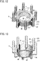
- Figs. 12 and 13 are perspective views illustrating the cast body 5 of the first embodiment.
- Fig. 12 shows the cast body 5 viewed from the upper end side of the riser part 20
- Fig. 13 shows the cast body 5 viewed from the lower end side of the riser part 20.
- the ring-shaped casting 4 is cast and the plurality of risers 21 are spaced in the circumferential direction S4 of the casting 4 and are connected to the rear-face part 4B of the casting 4.
- the cast body 5 is formed.
- the cast body 5 is a ring-shaped member 5A and has the plurality of parts of the risers 21 (riser parts 20) which are solidified and the casting 4 of the mold 1.
- the plurality of riser parts 20 project toward outside in the radial direction K4 of the casting 4 and are formed radially.
- an external force is applied to the ring-shaped member 5A and thus the shape of the casting 4 of the mold 1 is corrected by the external force.
- the casting 4 is deformed by the external force applied to the ring-shaped member 5A and a diameter or roundness of the casting 4 is corrected.
- a correction device an external force in the radial direction K4 is applied to the casting 4 and the diameter or roundness of the casting 4 is changed. In this way, the diameter or roundness of the casting 4 is corrected to a value in the predetermined tolerance level.
- the correction device is an expansion device (expanders etc.), a compression device or a pressurizing device.
- the correction device expansion device
- the casting 4 whole or a part
- the correction device compression device
- an external force is applied inwardly in the radial direction K4 to the casting 4, and the casting 4 (whole or a part) is compressed so that the diameter of the casting 4 is reduced. In this way, the diameter or roundness of the casting 4 is corrected.
- the ring-shaped casting 4 is reinforced by the plurality of riser parts 20.
- the casting 4 is thereby accurately corrected while the shape of the molding part 4A of the casting 4 is maintained.
- the end (upper end, lower end) in the width direction W4 of the casting 4 is suppressed to outwardly expand in the radial direction K4 with respect to the central part in the width direction W4 of the casting 4, and thus the whole of the casting 4 is accurately corrected.
- the plurality of riser parts 20 are removed from the ring-shaped member 5A by cutting or the like of the riser parts 20 and thus the casting 4 of the mold 1 is produced.
- the plurality of split molds 3 (cf. Fig. 1 ) of the mold 1 are formed from the casting 4.
- Fig. 14 is a perspective view illustrating examples of the conventional casting bodies 100, 101 and shows two casting bodies 100, 101 including the casting 4 of the mold 1.
- a plurality of columnar riser parts 103 are formed on the upper end of the casting 4 by solidification of the plurality of risers 102.
- one ring-shaped riser part 105 is formed on the upper end of the casting 4 by solidification of one riser 104.
- the risers 102, 104 are connected to the upper end of the casting 4, and the pathways from the risers 102, 104 to the lower end of the casting 4 are elongated. Therefore, the generation of the casting defect is concerned about, and the solidification time of the molten metal might become longer, too.
- the cast body 5 (cf. Fig. 12 ) of the first embodiment
- generation of the casting defect in the casting 4 of the mold 1 is easily suppressed and thus the manufacturing efficiency of the mold 1 can be improved.
- the quality of the casting 4 can be improved and the solidification time of the molten metal can be made shorter than ever before.
- the solidification of the molten metal can be easily adjusted by using a part of the molding flask 70 as the chiller 73.
- the heat conductivity of the storage part 50 is lower than the heat conductivity of the molding flask 70
- the solidification of the risers 21 can be suppressed and thus the molten metal of the risers 21 can be smoothly supplied.
- the generation of the casting defect air bubbles defect
- Fig. 15 is a perspective view illustrating a cast body 6 of the second embodiment and shows the cast body 6 as is the case in Fig. 12 .
- Fig. 16 is a perspective view illustrating the molten metal in the casting device 10 of the second embodiment and shows a part of the molten metal and the riser 21 in the casting space 11 as is the case in Fig. 11 .
- the supply path 54 and the connecting part 23 are inclined relative to the radial direction K4 of the casting 4.
- the connecting parts 23 of the plurality of risers 21 are each inclined toward the same side in the circumferential direction S4 of the casting 4 relative to the radial direction K4 of the casting 4, whereby the swirling current easily occurs in the riser body 22 and air bubbles can be certainly separated.
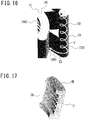
- Fig. 17 is a perspective view illustrating a casting 7 of the mold 1 of the third embodiment.
- Fig. 18 is a perspective view illustrating a cast body 8 of the third embodiment.
- the casting 7 is a casting of one split mold 3 of the plurality of split molds 3 (cf. Fig. 1 ) of the mold 1. Therefore, here, the mold 1 means the split mold 3.
- the casting 7 of the mold 1 (split mold 3) has a molding part 7A and a rear-face part 7B and is formed into a block shape.
- the molding part 7A of the casting 7 corresponds to the molding part 4A of the casting 4, and the rear-face part 7B of the casting 7 corresponds to the rear-face part 4B of the casting 4.
- One riser 21 is connected to a part of the rear-face part 7B, and the chiller is arranged on parts other than the riser 21 of the rear-face part 7B.
- the molding flask is arranged along both side parts and the rear-face part 7B of the casting 7, and the storage part 50.
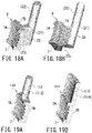
- Fig. 19 is a perspective view illustrating examples of the conventional cast bodies 110, 111 and shows two cast bodies 110, 111 including the casting 7 of the mold 1.
- a columnar riser part 113 is formed on the upper end of the casting 7 by solidification of a riser 112.
- a plate-like riser part 115 is formed on the upper end of the casting 7 by solidification of a riser 114.
- generation of the casting defect can be more easily suppressed than in the conventional cast bodies 110, 111.
- the castings 4, 7 may be cast by low-pressure casting.
- the cast bodies 5, 6, 8 are formed into an upside down shape to the shape shown in Fig. 12 , Fig. 15 , Fig. 18 .
- the molten metal is injected from the parts of each of the risers 21.
- a dam-type sprue runner (runner) is connected to the lower part of the casting 4 and the molten metal may be injected into the casting space 11 and the storage part 50 from the sprue runner.
- the first embodiment (cf. Fig. 12 ), eight risers 21 were arranged at equal intervals in the circumferential direction S4 of the casting 4, so that the cast body 5 was formed.
- the diameter of the riser body 22 was ⁇ 100mm, and the height of the riser body 22 is 600mm.
- the height of the connecting part 23 of the riser 21 was 270mm, and the width of the part connecting to the rear-face part 4B of the connecting part 23 was 30mm.
- the storage part 50 (width (110mm)) was arranged.
- Temperatures of the molding flask 70, the lower plate 34 and the upper plate 33 before injecting the molten metal were room temperatures (approximately 30 °C).
- the molten metal was injected thorough the dam-type sprue runner and the casting 4 was cast. Injection quantity of the molten metal was 7 kg per one second (7kg/sec). In the casting 4 of the first embodiment, the shrinkage cavity and air bubbles defect were scarcely generated in the casting 4 and thus generation of the casting defect was suppressed. Moreover, it was determined that the quality of the casting 4 was good.
- the first comparison example (cf. Fig. 14A ) is a competitive examination to the first embodiment.
- Eight risers 102 were arranged at equal intervals on the upper end of the casting 4 so that the cast body 100 was formed.
- the diameter of the riser 102 was ⁇ 90mm, and the height of the riser 102 was 300mm.
- Other conditions were the same as the conditions in the first embodiment.
- the casting 4 of the first comparison example there were relatively few air bubbles defects, but numerous shrinkage cavities were generated in the molding part 4A of the casting 4. Moreover, it was determined that the quality of the casting 4 was poor. In contrast, the change in the casting defect was not found even if the materials of the upper plate 33 was changed to the insulation material (calcium silicate board) or even if the molding flask was preheated to 250 °C.
- the molten metal was injected from the part of the riser 21 and, in the riser 21, air bubbles were separated from the molten metal by the swirling current.
- the risers 21 to inject the molten metal were the risers 21 in four storage parts 50 accommodating the gate members 60, respectively.
- the injection quantity (total values in four parts) of the molten metal was 16 kg per one second (16kg/sec). Other conditions were the same as the conditions in the first embodiment.
- the generation of the casting defect shrinkage cavity, air bubbles defect
- the generation of air bubbles defect was suppressed as with the casting 4 of the first embodiment, and it was determined that its quality was good.
- the generation of air bubbles defect was suppressed more certainly in the casting.
- the second comparison example (cf. Fig. 14A ) is a competitive examination to the second embodiment.
- the molten metal was injected from the parts of four risers 102 so that the cast body 100 was formed.
- the injection quantity (total values in four parts) of the molten metal was 16 kg per one second (16kg/sec).
- numerous shrinkage cavities were generated in the molding part 4A of the casting 4 as with the casting 4 of the first comparison example.
- numerous air bubbles defects ( ⁇ 0.3 - ⁇ 5mm) were generated in the molding part 4A of the casting 4, and it was determined that the quality of the casting 4 was poor.
- the external force was applied to the ring-shaped member 5A (cast body 5) formed in the second embodiment so that the diameter of the casting 4 was corrected.
- the correction of the casting 4 was performed while the plurality of riser parts 20 were connected to the casting 4.
- a force was applied outwardly in the radial direction K4 to the end (upper end, lower end) of the casting 4 so that a diameter of the central part of the casting 4 was increased by approximately 0.4mm.
- the plurality of riser parts 20 were removed.
- a change amount of the radius of the end was bigger by 0.07mm than the change amount of the radius of the central part. As a result, the difference in two change amounts was fallen in the tolerance range.
- the third comparison example (cf. Fig. 12 ) is a competitive examination to the third embodiment.
- the diameter of the central part of the casting 4 was increased by approximately 0.4mm as with the third embodiment.
- the change amount of the radius of the end was bigger by 0.21mm than the change amount of the radius of the central part. As a result, the difference in two change amounts is fallen out of the tolerance range.
Landscapes
- Engineering & Computer Science (AREA)
- Mechanical Engineering (AREA)
- Molds, Cores, And Manufacturing Methods Thereof (AREA)
Abstract
Description
- The present invention relates to a method for manufacturing a mold for tire, in which the mold is manufactured by casting.
- In the mold for tire, as a shape of a molding part for molding a tire is complicated, plate members (e.g., sipes or blades) which are separately manufactured are sometimes fixed to the molding part.
- Because of that, a casting process has been widely adopted for manufacturing the mold. Especially, when a gypsum mold is used, dimensional accuracy can be improved even if the mold is metal (e.g., aluminum alloy) casting having a relatively high melting point. Moreover, in the gypsum mold, cutting and assembling works can be easily carried out and plate members can be easily fixed (cast-in), too. The gypsum mold of a complicated shape can be easily formed by using a rubber mold.
- However, in the gypsum mold, solidification of a molten metal is delayed on the gypsum mold side due to its heat conduction property, and thus casting defects (shrinkage cavity etc.) are sometimes generated in the casting of the mold.
For coping with this, generation of casting defects has been conventionally suppressed by chillers and risers. For example, the chillers are each arranged on the lower side or the upper side relative to a gypsum mold and the risers are each arranged on the opposite side to each chiller. Generation of a closed space on the gypsum mold side is suppressed by making molten metal solidify from the chiller toward a riser, and thus casting defects are reduced. Moreover, a casting mold for low pressure casting has been known, in which a die for tire molding and vulcanization is cast by filling molten metal in the mold from the lower side by pressure of gas (cf. Patent Literature 1). - In the conventional casting mold for low pressure casting described in
Patent Literature 1, the molten metal is gradually solidified while the molten metal is pushed up through a stalk. However, in the casting mold for low pressure casting, as pathways from the riser in the stalk to the upper end of the casting is elongated, it is difficult to control a solidification direction of the molten metal. Moreover, as parts other than the casting in the die are solidified earlier, it is concerned that a supply of the molten metal to the parts of the casting would be obstructed. When a casting defect is generated, it is required to take countermeasures for the defect (the disposal or repair of casting, etc.), and thus the manufacturing efficiency of the die may be decreased. Therefore, also in a viewpoint of the manufacturing efficiency, it is required to easily suppress generation of the casting defect. - Patent Literature 1: Japanese Patent Laid-Open No.
S57-58968 - The present invention has been made in view of the above-described conventional problems and an object thereof is to easily suppress the generation of a casting defect in the casting of the mold when the mold for tire is manufactured by casting, so that the manufacturing efficiency of the mold is improved.
- The present invention is a method for manufacturing a mold for tire by molding parts arranged along a tire width direction, wherein the mold for tire is manufactured by casting. A width direction of a casting of the mold corresponding to the tire width direction is matched with a vertical direction, a riser is connected to a part of a rear-face part of the casting located on a back side of the molding parts and a chiller is arranged on the part other than the riser of the rear -face part.
- According to the present invention, when the mold for tire is manufactured by casting, the generation of the casting defect in the casting of the mold is easily suppressed, and thus the manufacturing efficiency of the mold can be improved.
-
-
Fig. 1 is a plan view of a mold of a first embodiment; -
Fig. 2 is a sectional view of the mold of the first embodiment; -
Fig. 3 is a perspective view illustrating a casting of the mold of the first embodiment; -
Fig. 4 is a perspective view illustrating a casting device for the mold of the first embodiment; -
Fig. 5 is a perspective view illustrating the casting device for the mold of the first embodiment; -
Fig. 6 is a perspective view illustrating the casting device for the mold of the first embodiment; -
Fig. 7 is a perspective view illustrating the casting device for the mold of the first embodiment; -
Fig. 8 is a perspective view illustrating the casting device for the mold of the first embodiment; -
Fig. 9 is a sectional view illustrating the casting device for the mold of the first embodiment; -
Fig. 10 is a sectional view illustrating a part of the casting device including a storage part for a riser; -
Fig. 11 is a perspective view illustrating a molten metal in the casting device of the first embodiment; -
Fig. 12 is a perspective view illustrating a cast body of the first embodiment; -
Fig. 13 is a perspective view illustrating the cast body of the first embodiment; -
Fig. 14 is a perspective view illustrating examples of a conventional cast bodies; -
Fig. 15 is a perspective view illustrating a cast body of a second embodiment; -
Fig. 16 is a perspective view illustrating the molten metal in the casting device of the second embodiment; -
Fig. 17 is a perspective view illustrating a casting of a mold of a third embodiment; -
Fig. 18 is a perspective view illustrating a cast body of the third embodiment -
Fig. 19 is a perspective view illustrating examples of a conventional cast bodies. - An embodiment of a method for manufacturing a mold for tire will be described with reference to the attached drawings.
- In the method for manufacturing a mold of the present embodiment, the mold is manufactured by casting, in which the mold having the shape corresponding to the shape of the tire is formed. The mold is a vulcanizing mold for tires and is used at the time of molding of the tire (at the time of vulcanization). The tire is vulcanized while it is molded by the mold.
-
Fig. 1 is a plan view of amold 1 of the first embodiment and shows themold 1 viewed from the outside in a width direction of atire 2.Fig. 2 is a sectional view of themold 1 of the first embodiment and shows themold 1 which is cut along the line X1-X1 inFig. 1 . InFigs. 1 and 2 , thetire 2 molded by themold 1 is schematically shown by a dot-dash line. - As illustrated, the
mold 1 is a ring-shaped outer die for molding the outside of thetire 2 and is provided in a molding device (vulcanizer) for thetire 2. Themold 1 forms atread part 2A of thetire 2 while surrounding a ring-shaped tire 2. - With respect to directions of the
mold 1 and thetire 2, a width direction (mold width direction W1) of themold 1 corresponds to the width direction (tire width direction W2) of thetire 2. Moreover, a radial direction (mold radial direction K1) of themold 1 corresponds to the radial direction (tire radial direction K2) of thetire 2 and a circumferential direction (mold circumferential direction S1) of themold 1 corresponds to a circumferential direction (tire circumferential direction S2) of thetire 2. - The
mold 1 comprises a plurality of (here nine)split molds 3 successively arranged along the tire circumferential direction S2 (mold circumferential direction S1). The plurality ofsplit molds 3 are segments divided in the mold circumferential direction S1 and are tread molds which form thetread part 2A of thetire 2. - In the
mold 1, each of thesplit molds 3 has amolding part 3A formed on thetire 2 side and a rear-face part 3B formed on a rear-face side. In themold 1 and thesplit molds 3, the rear-face part 3B is located on the opposite side to themolding part 3A (the outside in the tire radial direction K2 (mold radial direction K1)). - At the time of molding the
tire 2, the plurality ofsplit molds 3 are put together into a ring shape with their ends being in contact each other and surround thetire 2. In such state, themold 1 and themolding parts 3A are arranged along the tire width direction W2 (mold width direction W1). Themold 1 is in contact with the tire 2 (treadpart 2A) at themolding parts 3A ofsplit mold 3 and molds thetire 2 with themolding part 3A. Themolding part 3A molds recessed parts (e.g., grooves, sipes) on thetread part 2A of thetire 2 with a plurality ofprojections 3C. -
Fig. 3 is a perspective view illustrating acasting 4 of themold 1 of the first embodiment. - As illustrated, the
mold 1 is a die manufactured by metal (e.g., aluminum alloy) casting, and is made from thecasting 4. Thecasting 4 is a product part of a cast body which shall be themold 1, and is formed by casting. The plurality ofsplit molds 3 are formed, for example, by dividing a ring-shapedcasting 4 in a circumferential direction S4 (mold circumferential direction S1). Therefore, the casting 4 of themold 1 is a material (mold material) of themold 1 and thesplit molds 3, and includes a casting of the plurality ofsplit molds 3. Thecasting 4 is formed into a ring shape, corresponding to a ring-shapedmold 1. - The casting 4 of the
mold 1 has amolding part 4A corresponding to themolding part 3A of the mold 1 (split mold 3) and a rear-face part 4B located on the rear-face side of themolding part 3A (molding part 4A). - The
molding part 4A is an internal peripheral part of thecasting 4, which is formed into a ring shape on the inner part in a radial direction K4 (mold radial direction K1) of thecasting 4. The rear-face part 4B is an outer peripheral part of thecasting 4 located on the side opposite to themolding part 4A and is formed into a ring shape on an outer part in the radial direction K4 of thecasting 4. The rear-face part 4B is a part corresponding to the rear-face part 3B of themold 1 and is formed on the opposite side (rear face side) of thecasting 4 to themolding part 3A (molding part 4A). - A width direction W4 of the
casting 4 is a direction corresponding to the mold width direction W1 and the tire width direction W2, and the circumferential direction S4 of thecasting 4 is a direction corresponding to the mold circumferential direction S1 and the tire circumferential direction S2. - Moreover, the radial direction K4 of the
casting 4 is a direction corresponding to the mold radial direction K1 and the tire radial direction K2. The casting 4 of themold 1 is cast by a casting device of themold 1 and is formed integrally with other parts (riser parts etc.). At the time of casting thecasting 4, the width direction W4 of thecasting 4 is arranged along the vertical direction. -
Figs. 4 to 8 are perspective views illustrating acasting device 10 for themold 1 of the first embodiment.Fig. 4 shows the whole of thecasting device 10 which is decomposed, andFigs. 5 to 8 show thecasting device 10, wherein each part of which is successively put together with the other part thereof. - As illustrated, the
casting device 10 forms a ring-shaped cast body 5 (cf.Fig. 4 ) including the casting 4 of themold 1 and a plurality ofriser parts 20 by casting (here, gravity casting). The plurality ofriser parts 20 are the parts of the risers that are solidified, respectively, and are successively formed along the circumferential direction S4 of thecasting 4 and are connected to the rear-face part 4B of thecasting 4. - The
casting device 10 comprises a disk-shaped table 30, a disk-shapedsurface plate 31, a plurality ofheat insulation materials 32, a ring-shapedcasting mold 40, a plurality ofstorage parts 50 for the riser and a disk-shapedupper plate 33, a plurality ofgate members 60 and a ring-shapedmolding flask 70. - The surface plate 31 (cf.
Fig. 5 ) is arranged in the central part of the table 30 and is held by the table 30. The plurality ofheat insulation materials 32 are arranged around thesurface plate 31 on an upper surface part of the table 30. Moreover, the plurality ofheat insulation materials 32 are arranged at equal intervals along an outer peripheral part of thesurface plate 31. The castingmold 40 is mounted on thesurface plate 31 and is arranged in the central part of the table 30. The plurality ofgate members 60 extend upward from theheat insulation materials 32 and are arranged so as to surround the castingmold 40. - The plurality of storage parts 50 (cf.
Fig. 6 ) for the riser are put on theheat insulation materials 32, respectively, and are arranged around the castingmold 40. - Moreover, the plurality of
storage parts 50 are arranged at the positions separated from the castingmold 40 and surround the castingmold 40 at the outside of the castingmold 40. Eightstorage parts 50 are arranged at equal intervals along an outer peripheral part of the castingmold 40, and thegate members 60 are accommodated within fourstorage parts 50, respectively.
Thestorage part 50 accommodating thegate member 60 and thestorage part 50 not accommodating thegate members 60 are alternately arranged along the outer peripheral part of the castingmold 40. The outer peripheral part of the castingmold 40 is amold part 41 to form themolding part 4A of thecasting 4, and thestorage parts 50 are opposite to themold part 41 of the castingmold 40. - The molding flask 70 (cf.
Fig. 4 ) has a plurality of opposingparts 71 opposite to themold part 41 of the castingmold 40 and a plurality of projectingparts 72 projecting from the opposingparts 71 towards the opposite side to the castingmold 40.
The opposingparts 71 and the projectingparts 72 are each alternatively formed, and the plurality of the projectingparts 72 project radially. The molding flask 70 (cf.Fig. 7 ) is mounted on the table 30 and surrounds the castingmold 40 and the plurality ofstorage parts 50. The whole of the castingmold 40 and the lower parts of thestorage parts 50 are accommodated inside themolding flask 70. - The plurality of
storage parts 50 are arranged inside the projectingparts 72 of themolding flask 70 and are held in the projectingparts 72, respectively. The opposingpart 71 of themolding flask 70 is located betweenadjacent storage parts 50. The opposingparts 71 of themolding flask 70 and the parts on the castingmold 40 side of thestorage parts 50 form a ring-shaped wall part continuing along the outer peripheral part (mold part 41) of the castingmold 40 and are opposite to themold part 41 of the castingmold 40. The upper plate 33 (cf.Fig. 8 ) is mounted on the castingmold 40 and themolding flask 70 and brought into contact with the upper end of the castingmold 40 and the opposingparts 71 of themolding flask 70. -
Fig. 9 is a sectional view illustrating thecasting device 10 for themold 1 of the first embodiment and shows thecasting device 10 cut along the line X2-X2 inFig. 8 . InFig. 9 , thegate member 60 is schematically shown by a dot-dash line. - As illustrated, the
casting device 10 comprises alower plate 34 consisting of the table 30 and thesurface plate 31. Thesurface plate 31 is accommodated in a recessedpart 35 of the table 30, and thus an upper surface of thesurface plate 31 and the upper surface of the table 30 are continuous. - The
upper plate 33 is arranged above thelower plate 34, and theupper plate 33 and thelower plate 34 are opposite to each other in the vertical direction. The castingmold 40 is a mold member to mold themolding part 4A of thecasting 4 by themold part 41. Moreover, the castingmold 40 is a gypsum mold made of gypsum, and is arranged inside themolding flask 70 and the plurality ofstorage parts 50 for theriser 21. Themold part 41 of the castingmold 40 is formed in a shape corresponding to the shape of the tire 2 (treadpart 2A) formed by themold 1 and is provided on the outer peripheral part of the castingmold 40. - The casting
mold 40, the opposingparts 71 of themolding flask 70 and the parts on the castingmold 40 side of thestorage parts 50 are arranged between thelower plate 34 and theupper plate 33. A castingspace 11 of thecasting 4 is formed by the castingmold 40, the opposingparts 71 of themolding flask 70, thestorage parts 50, thelower plate 34 and theupper plate 33.
The castingspace 11 is a space to cast the casting 4 of themold 1, and is formed into a ring shape in thecasting device 10. An upper end of the castingspace 11 is defined by theupper plate 33, and a lower end of the castingspace 11 is defined by thelower plate 34. An internal peripheral part of the castingspace 11 is defined by the casting mold 40 (mold part 41), and an outer peripheral part of the castingspace 11 is defined by the opposingparts 71 of themolding flask 70 and thestorage parts 50. - When the casting 4 of the
mold 1 is cast, the molten metal is injected into the castingspace 11 by using somestorage parts 50 of the plurality ofstorage parts 50 as injection parts (casting parts) of the molten metal. The injection part of molten metal is thestorage part 50 accommodating thetubular gate member 60. - The molten metal is injected into the
storage part 50 through thegate member 60 and is stored in thestorage part 50. Moreover, the molten metal is injected into the castingspace 11 from thestorage part 50 and thus is filled in the castingspace 11. In thestorage part 50 without accommodating thegate member 60, the molten metal is injected into thestorage part 50 from the castingspace 11 and is stored in thestorage part 50.
The molten metal in the plurality ofstorage parts 50 shall berisers 21 for the castingspace 11 and the casting 4.A plurality ofrisers 21 are successively arranged along the circumferential direction S4 of thecasting 4 and are separated from each other in the circumferential direction S4 of thecasting 4. Here, eightrisers 21 are arranged at equal intervals along the circumferential direction S4 of the casting 4 (circumferential direction of the casting space 11). - The plurality of
heat insulation materials 32 are sheet materials having heat insulation characteristics and are provided between thestorage parts 50 and the lower plate 34 (here the table 30), respectively. Thestorage part 50 is a hollow riser cell to store therisers 21 and supplies the castingspace 11 with the molten metal of theriser 21. Moreover, thestorage part 50 has acylindrical accommodation part 51 accommodating theriser 21 and asupply part 52 located between theaccommodation part 51 and the castingspace 11. Theaccommodation part 51 is arranged upward from thelower plate 34 and projects upward relative to thesupply part 52. Thesupply part 52 connects theaccommodation part 51 to the castingspace 11 and supplies theriser 21 in theaccommodation part 51 towards the castingspace 11. The molten metal of theriser 21 is supplied to the castingspace 11 through thesupply part 52. - The space in the
accommodation space 51 is an accommodation part 53 (storage space) which accommodates theriser 21, and the space in thesupply part 52 is a supply path 54 (supply passage) of theriser 21. Thesupply path 54 is located between theaccommodation space 53 of theriser 21 and the castingspace 11 and is opened towards theaccommodation space 53 and the castingspace 11. Theriser 21 is supplied to the castingspace 11 from theaccommodation space 53 through thesupply path 54. - In the
riser 21 stored in thestorage part 50, theriser 21 in the storage part 51 (accommodation space 53) is a main body of the riser 21 (riser body 22) and theriser 21 in the supply path 52 (supply passage 54) is a connectingpart 23 of theriser 21.
Thesupply passage 54 and the connectingpart 23 are formed along the radial direction K4 of thecasting 4. In thestorage part 50, the connectingpart 23 is located between theriser body 22 and the castingspace 11 and connects theriser body 22 to the castingspace 11 and supplies the riser 21 (molten metal) of theriser body 22 to the castingspace 11. -
Fig. 10 is a sectional view illustrating a part of thecasting device 10 including thestorage part 50 for theriser 21 and shows thecasting device 10 cut along the line X3-X3 inFig. 9 . - As illustrated, when viewed in a horizontal section, the
supply path 54 in thesupply part 52 is thinner than theaccommodation space 53 in theaccommodation part 51, and becomes narrower towards the castingspace 11 from theaccommodation space 53. The connectingpart 23 of theriser 21 becomes thinner (narrower) than theriser body 22 by making thesupply path 54 thinner (narrower) than theaccommodation space 53. - The
upper plate 33, thelower plate 34 and the molding flask 70 (cf.Fig. 9 ) are made of metal (e.g., steel, cast iron) and are used aschillers upper plate 33 is achiller 36 on an upper end side (the first chiller) which performs cooling at the upper end of thecasting 4, and thelower plate 34 is achiller 37 on a lower end side (the second chiller) which performs cooling at the lower end of thecasting 4.
The opposingpart 71 of themolding flask 70 is achiller 73 on a rear-face side (the third chiller) which performs cooling on the rear-face part 4B of thecasting 4, and is arranged between twochillers mold 1 is cast, thechillers space 11, so that thechillers casting 4. Moreover, thechiller 73 is put on a rear-face of the castingspace 11, so that thechiller 73 is arranged on a part of the rear-face part 4B of thecasting 4. - The upper end and the lower end of the casting
space 11 are parts corresponding to the upper end and the lower end of thecasting 4, respectively, and the rear-face part of the castingspace 11 is a part corresponding to the rear-face part 4B of thecasting 4. Thechillers space 11 and in contact with the molten metal. The casting 4 of themold 1 is cast while solidification (cooling) of the molten metal in the castingspace 11 is adjusted by thechillers
The upper end of thecasting 4 is molded by the chiller 36 (upper plate 33), and the lower end of thecasting 4 is molded by the chiller 37 (lower surface 34). Moreover, themolding part 4A of thecasting 4 is molded by themold part 41 of the castingmold 40 and the rear-face part 4B of thecasting 4 is molded by the chiller 73 (opposingpart 71 of the molding flask 70) and thestorage part 50. Thestorage part 50 is made of materials (e.g., sand, ceramic) having lower heat conductivity than that of theupper plate 33, thelower plate 34 and themolding flask 70. - The
molding flask 70 made of metal and thestorage part 50 having lower heat conductivity than themolding flask 70 are arranged at the rear-face side of the castingspace 11 and thus are arranged on the rear-face part 4B side of thecasting 4. When thecasting 4 is cast, theriser 21 in thestorage part 50 is supplied to a part of the back part of the castingspace 11 and thus is connected to a part of the rear-face part 4B of thecasting 4. Moreover, a part in contact with themolding flask 70 of the rear-face part 4B is formed by themolding flask 70 while using a part in contact with the rear-face part 4B of themolding flask 70 as thechiller 73. The part in contact with the rear-face part 4B of themolding flask 70 is the opposingpart 71 of themolding flask 70. The opposing part 71 (chiller 73) and the storage part 50 (riser 21) are alternately arranged along the rear-face part 4B. Each of thechillers 73 is arranged between two risers 21 (connecting part 23), and each of therisers 21 is arranged between twochillers 73. - When the casting 4 of the
mold 1 is cast, the width direction W4 of thecasting 4 is matched with the vertical direction and, in thecasting device 10, the castingspace 11 of thecasting 4 is formed in thecasting device 10. Moreover, thestorage part 50 for theriser 21 is connected to only a part of the rear-face part side of the castingspace 11, so that theriser 21 is connected to only a part of the rear-face part 4B of thecasting 4.
In thestorage part 50, theriser 21 of theriser body 22 is supplied towards the castingspace 11 through the connectingpart 23 which is thinner than theriser body 22, so that theriser 21 and theriser body 22 are connected to the rear-face part 4B of thecasting 4. The chiller 73 (opposingpart 71 of the molding flask 70) is put on parts other than thestorage part 50 on the rear-face part side of the castingspace 11, so that thechiller 73 is arranged on the part other than theriser 21 of the rear-face part 4B of thecasting 4. With this, thechiller 73 is arranged on parts other than the connectingpart 23 in the rear-face part 4B. In the rear-face part 4B, thechiller 73 is arranged on some part of parts other than theriser 21 and the connectingpart 23. - The molten metal is injected into the storage part 50 (accommodation part 51) through the
gate member 60 and is injected into the castingspace 11 from thestorage part 50. The molten metal is injected into the accommodation part 51 (accommodation space 53) and is then injected into the castingspace 11 through the supply part 52 (supply path 54). Thegate member 60 is a supply pipe for the molten metal accommodated within theaccommodation part 51 and is arranged along the vertical direction. Anupper end 61 of thegate member 60 is placed at an upper end of theaccommodation part 51, and alower end 62 of thegate member 60 is located at a lower end of theaccommodation part 51. - The molten metal is injected into the
upper end 61 of thegate member 60 and is then supplied into thestorage part 50 from thelower end 62 of thegate member 60. Thelower end 62 of thegate member 60 bends towards the side opposite to the casting space 11 (casting 4) and is arranged along a wall surface of theaccommodation part 51. By thelower end 62 of thegate member 60, the molten metal is supplied along the wall surface of theaccommodation part 51 and flows along the wall surface ofaccommodation part 51. -
Fig. 11 is a perspective view illustrating the molten metal in thecasting device 10 of the first embodiment and shows a part of the molten metal in the castingspace 11 and theriser 21. - As illustrated, since the molten metal flows along the wall surface of the
accommodation part 51 in thestorage part 50 accommodating thegate member 60, a swirling current of the molten metal occurs in theriser body 22 in the accommodation part 51 (cf. arrow F). In this way, air bubbles in the molten metal is floated in theriser 21 and separated from the molten metal. - At the time of injection of the molten metal, gas (air etc.) is drawn into the molten metal, and air bubbles are generated in the molten metal. In the molten metal, buoyancy acts on air bubbles. Moreover, by swirling current, a centrifugal force acts on the molten metal, and a power (centripetal force) toward a center of the swirling current acts on air bubbles. Air bubbles move towards the center of the swirling current while being carried by the swirling current. The center of the swirling current is the stagnant portion of the molten metal, and air bubbles are gathered in the center of the swirling current. In the center of the swirling current, air bubbles are floated in the molten metal and thus is separated from the molten metal.
- The molten metal is injected into the casting
space 11 from the parts of theriser 21 while air bubbles are removed from the molten metal (cf.Fig. 9 ) and the molten metal is cast in the castingspace 11. Moreover, the molten metal is filled in the castingspace 11 and theriser 21 is stored in thestorage part 50. The molten metal in the castingspace 11 is cooled by thechillers space 11 from theriser 21. The molten metal in the castingspace 11 is solidified and thus the casting 4 of themold 1 is cast. Moreover, theriser 21 in thestorage part 50 is solidified, and the solidifiedriser part 20 is formed in thestorage part 50. - Due to heat conduction properties of the casting
mold 40 made of gypsum, the solidification of the molten metal is started from thechillers mold 40 side. On the rear-face part 4B side of thecasting 4, the solidification of the molten metal is started from thechiller 73 and progressed towards the castingmold 40. With this, the solidification of the molten metal is progressed in a thickness direction of thecasting 4, and molten metal is solidified from the rear-face part 4B of thecasting 4 to themolding part 4A. On this occasion, the molten metal is smoothly supplied to the castingspace 11 in accordance with solidification of the molten metal by supplying the molten metal of theriser 21 from the rear-face part 4B side. Moreover, the molten metal of theriser 21 is surely supplied because pathways from theriser 21 to themolding part 4A become shorter than ever before. In this way, a casting defect (e.g., shrinkage cavity) occuring in thecasting 4 can be retrained. The solidification time of the molten metal is shortened because the solidification of the molten metal is progressed from the position of thechiller 73 to the circumferential direction S4 of thecasting 4. - In the upper end side and the lower end side of the
casting 4, solidification of the molten metal is started from thechillers casting 4. In this way, moreover to the solidification of the molten metal from the rear-face part 4B side, the solidification of the molten metal is progressed along themold part 41 of the castingmold 40. Therefore, the generation of the casting defect is suppressed while the solidification time of the molten metal is shortened. After solidification of the molten metal in thecasting device 10 has been completed, thecasting device 10 is dismantled, and the cast body 5 is taken out. -
Figs. 12 and 13 are perspective views illustrating the cast body 5 of the first embodiment.Fig. 12 shows the cast body 5 viewed from the upper end side of theriser part 20, andFig. 13 shows the cast body 5 viewed from the lower end side of theriser part 20. - As illustrated, when the casting 4 of the
mold 1 is cast, the ring-shapedcasting 4 is cast and the plurality ofrisers 21 are spaced in the circumferential direction S4 of thecasting 4 and are connected to the rear-face part 4B of thecasting 4. In this way, the cast body 5 is formed. The cast body 5 is a ring-shapedmember 5A and has the plurality of parts of the risers 21 (riser parts 20) which are solidified and the casting 4 of themold 1. The plurality ofriser parts 20 project toward outside in the radial direction K4 of thecasting 4 and are formed radially. - After the ring-shaped
member 5A (cast body 5) has been formed, an external force is applied to the ring-shapedmember 5A and thus the shape of the casting 4 of themold 1 is corrected by the external force. Here, thecasting 4 is deformed by the external force applied to the ring-shapedmember 5A and a diameter or roundness of thecasting 4 is corrected. For example, by a correction device, an external force in the radial direction K4 is applied to thecasting 4 and the diameter or roundness of thecasting 4 is changed. In this way, the diameter or roundness of thecasting 4 is corrected to a value in the predetermined tolerance level. For example, the correction device is an expansion device (expanders etc.), a compression device or a pressurizing device. - By the correction device (expansion device), an external force is applied outwardly in the radial direction K4 to the
casting 4 and the casting 4 (whole or a part) is expanded, so that the diameter of thecasting 4 is increased. In contrast, by the correction device (compression device), an external force is applied inwardly in the radial direction K4 to thecasting 4, and the casting 4 (whole or a part) is compressed so that the diameter of thecasting 4 is reduced. In this way, the diameter or roundness of thecasting 4 is corrected. - When the
casting 4 is corrected, the ring-shapedcasting 4 is reinforced by the plurality ofriser parts 20. Thecasting 4 is thereby accurately corrected while the shape of themolding part 4A of thecasting 4 is maintained. - Moreover, the end (upper end, lower end) in the width direction W4 of the
casting 4 is suppressed to outwardly expand in the radial direction K4 with respect to the central part in the width direction W4 of thecasting 4, and thus the whole of thecasting 4 is accurately corrected. After correction of thecasting 4, the plurality ofriser parts 20 are removed from the ring-shapedmember 5A by cutting or the like of theriser parts 20 and thus the casting 4 of themold 1 is produced. Successively, the plurality of split molds 3 (cf.Fig. 1 ) of themold 1 are formed from thecasting 4. -
Fig. 14 is a perspective view illustrating examples of theconventional casting bodies bodies mold 1. - As illustrated, in one cast body 100 (cf.
Fig. 14A ), a plurality ofcolumnar riser parts 103 are formed on the upper end of thecasting 4 by solidification of the plurality ofrisers 102. In the other cast body 101 (cf.Fig. 14B ), one ring-shapedriser part 105 is formed on the upper end of thecasting 4 by solidification of oneriser 104. In theconventional cast bodies risers casting 4, and the pathways from therisers casting 4 are elongated. Therefore, the generation of the casting defect is concerned about, and the solidification time of the molten metal might become longer, too. - In contrast, in the cast body 5 (cf.
Fig. 12 ) of the first embodiment, generation of the casting defect in thecasting 4 of themold 1 is easily suppressed and thus the manufacturing efficiency of themold 1 can be improved. Moreover, the quality of thecasting 4 can be improved and the solidification time of the molten metal can be made shorter than ever before.
The solidification of the molten metal can be easily adjusted by using a part of themolding flask 70 as thechiller 73. As the heat conductivity of thestorage part 50 is lower than the heat conductivity of themolding flask 70, the solidification of therisers 21 can be suppressed and thus the molten metal of therisers 21 can be smoothly supplied. The generation of the casting defect (air bubbles defect) can be easily suppressed by separating the air bubbles in therisers 21. - Outflow of air bubbles from the
risers 21 is suppressed by making the connectingpart 23 of therisers 21 thinner than theriser body 22, so that, in therisers 21, the air bubbles can be certainly separated. Moreover, since the swirling current easily occurs in theriser body 22, air bubbles can be certainly separated in the center of the swirling current. As the volume of the connectingpart 23 becomes small, the quantity of theriser 21 can be also reduced. Theriser part 20 can be easily removed by separating theriser part 20 from the casting 4 at the position of the connectingpart 23. - Next, the other embodiments will be explained. With respect to following other embodiments, description about matters same as those of the first embodiment is omitted and the matters differing from those of the first embodiment will be described.
-
Fig. 15 is a perspective view illustrating acast body 6 of the second embodiment and shows thecast body 6 as is the case inFig. 12 .Fig. 16 is a perspective view illustrating the molten metal in thecasting device 10 of the second embodiment and shows a part of the molten metal and theriser 21 in the castingspace 11 as is the case inFig. 11 . - As illustrated, in the
supply part 52 of thestorage part 50, thesupply path 54 and the connectingpart 23 are inclined relative to the radial direction K4 of thecasting 4. The connectingparts 23 of the plurality ofrisers 21 are each inclined toward the same side in the circumferential direction S4 of thecasting 4 relative to the radial direction K4 of thecasting 4, whereby the swirling current easily occurs in theriser body 22 and air bubbles can be certainly separated. -
Fig. 17 is a perspective view illustrating acasting 7 of themold 1 of the third embodiment.Fig. 18 is a perspective view illustrating acast body 8 of the third embodiment. - As illustrated, the
casting 7 is a casting of onesplit mold 3 of the plurality of split molds 3 (cf.Fig. 1 ) of themold 1. Therefore, here, themold 1 means thesplit mold 3. The casting 7 of the mold 1 (split mold 3) has amolding part 7A and a rear-face part 7B and is formed into a block shape. Themolding part 7A of thecasting 7 corresponds to themolding part 4A of thecasting 4, and the rear-face part 7B of thecasting 7 corresponds to the rear-face part 4B of thecasting 4. Oneriser 21 is connected to a part of the rear-face part 7B, and the chiller is arranged on parts other than theriser 21 of the rear-face part 7B. The molding flask is arranged along both side parts and the rear-face part 7B of thecasting 7, and thestorage part 50. -
Fig. 19 is a perspective view illustrating examples of theconventional cast bodies bodies mold 1. - As illustrated, in one cast body 110 (cf.
Fig. 19A ), acolumnar riser part 113 is formed on the upper end of thecasting 7 by solidification of ariser 112. In the other cast body 111 (cf.Fig. 19B ), a plate-like riser part 115 is formed on the upper end of thecasting 7 by solidification of ariser 114. In thecast body 8 of the casting 7 of the third embodiment, generation of the casting defect can be more easily suppressed than in theconventional cast bodies - As mentioned above, while examples in which the
castings castings cast bodies Fig. 12 ,Fig. 15 ,Fig. 18 . The molten metal is injected from the parts of each of therisers 21. Moreover, separately from theriser 21, a dam-type sprue runner (runner) is connected to the lower part of thecasting 4 and the molten metal may be injected into the castingspace 11 and thestorage part 50 from the sprue runner. - To confirm an effect of the present invention, a test to cast the casting 4 of the
mold 1 was performed by the manufacturing method described above. The examination condition is as follows. - Shape of the casting 4: Ring shape including the casting of nine split
molds 3 - Dimensions of the casting 4: Inner diameter (ø 600mm), width (300mm), the smallest wall thickness (50mm)
- Materials of the casting mold 40: Non-foaming gypsum (product made by Noritake Co., Ltd., product name: G-6)
- Materials of the casting 4 (molten metal): Aluminum alloy (AC7A: Japanese Industrial Standards) (4% Mg, 0.2% Si)
- Molding flask 70: Ring-shaped molding flask made from spherical black lead cast iron, the height (300mm), the wall thickness (30-50mm)
- Materials of the lower plate 34 (table 30, surface plate 31): Steel materials for general structure (SS400: Japanese Industrial Standards)
- Materials of the upper plate 33: Steel materials for general structure (SS400: Japanese Industrial Standards)
- Materials of the storage part 50: Insulation material (molding product of the ceramic fiber)
- Temperature of the molten metal: 670 °C
- In the first embodiment (cf.
Fig. 12 ), eightrisers 21 were arranged at equal intervals in the circumferential direction S4 of thecasting 4, so that the cast body 5 was formed. The diameter of theriser body 22 was ø 100mm, and the height of theriser body 22 is 600mm. The height of the connectingpart 23 of theriser 21 was 270mm, and the width of the part connecting to the rear-face part 4B of the connectingpart 23 was 30mm.
Around theriser 21, the storage part 50 (width (110mm)) was arranged. Temperatures of themolding flask 70, thelower plate 34 and theupper plate 33 before injecting the molten metal were room temperatures (approximately 30 °C). The molten metal was injected thorough the dam-type sprue runner and thecasting 4 was cast. Injection quantity of the molten metal was 7 kg per one second (7kg/sec). In thecasting 4 of the first embodiment, the shrinkage cavity and air bubbles defect were scarcely generated in thecasting 4 and thus generation of the casting defect was suppressed. Moreover, it was determined that the quality of thecasting 4 was good. - The first comparison example (cf.
Fig. 14A ) is a competitive examination to the first embodiment. Eightrisers 102 were arranged at equal intervals on the upper end of thecasting 4 so that thecast body 100 was formed. The diameter of theriser 102 was ø 90mm, and the height of theriser 102 was 300mm. Other conditions were the same as the conditions in the first embodiment. In thecasting 4 of the first comparison example, there were relatively few air bubbles defects, but numerous shrinkage cavities were generated in themolding part 4A of thecasting 4. Moreover, it was determined that the quality of thecasting 4 was poor. In contrast, the change in the casting defect was not found even if the materials of theupper plate 33 was changed to the insulation material (calcium silicate board) or even if the molding flask was preheated to 250 °C. - In the second embodiment (cf.
Fig. 11 ), the molten metal was injected from the part of theriser 21 and, in theriser 21, air bubbles were separated from the molten metal by the swirling current. Therisers 21 to inject the molten metal were therisers 21 in fourstorage parts 50 accommodating thegate members 60, respectively. - The injection quantity (total values in four parts) of the molten metal was 16 kg per one second (16kg/sec). Other conditions were the same as the conditions in the first embodiment. In the
casting 4 of the second embodiment, the generation of the casting defect (shrinkage cavity, air bubbles defect) was suppressed as with the casting 4 of the first embodiment, and it was determined that its quality was good. Moreover, the generation of air bubbles defect was suppressed more certainly in the casting. - The second comparison example (cf.
Fig. 14A ) is a competitive examination to the second embodiment. In contrast to the first comparison example, the molten metal was injected from the parts of fourrisers 102 so that thecast body 100 was formed. The injection quantity (total values in four parts) of the molten metal was 16 kg per one second (16kg/sec). In thecasting 4 of the second comparison example, numerous shrinkage cavities were generated in themolding part 4A of thecasting 4 as with the casting 4 of the first comparison example. Moreover, numerous air bubbles defects (ø 0.3 - ø 5mm) were generated in themolding part 4A of thecasting 4, and it was determined that the quality of thecasting 4 was poor. - In the third embodiment (cf.
Fig. 12 ), the external force was applied to the ring-shapedmember 5A (cast body 5) formed in the second embodiment so that the diameter of thecasting 4 was corrected. The correction of thecasting 4 was performed while the plurality ofriser parts 20 were connected to thecasting 4. - Moreover, a force was applied outwardly in the radial direction K4 to the end (upper end, lower end) of the
casting 4 so that a diameter of the central part of thecasting 4 was increased by approximately 0.4mm. After correction of thecasting 4, the plurality ofriser parts 20 were removed. In thecasting 4 of the third embodiment, a change amount of the radius of the end was bigger by 0.07mm than the change amount of the radius of the central part. As a result, the difference in two change amounts was fallen in the tolerance range. - The third comparison example (cf.
Fig. 12 ) is a competitive examination to the third embodiment. After the plurality ofriser parts 20 were removed from the ring-shapedmember 5A formed in the second embodiment, the diameter of the central part of thecasting 4 was increased by approximately 0.4mm as with the third embodiment. In thecasting 4 of the third comparison example, the change amount of the radius of the end was bigger by 0.21mm than the change amount of the radius of the central part. As a result, the difference in two change amounts is fallen out of the tolerance range. -
- 1
- mold
- 2
- tire
- 3
- split mold
- 4
- casting
- 5
- cast body
- 6
- cast body
- 7
- casting
- 8
- cast body
- 10
- casting device
- 11
- casting space
- 20
- riser part
- 21
- riser
- 22
- riser body
- 23
- connecting part
- 30
- table
- 31
- surface plate
- 32
- insulation material
- 33
- upper plate
- 34
- lower plate
- 35
- recessed part
- 36
- chiller
- 37
- chiller
- 40
- casting mold
- 41
- mold part
- 50
- storage part
- 51
- accommodating part
- 52
- supply part
- 53
- accommodation space
- 54
- supply path
- 60
- gate member
- 61
- upper end
- 62
- lower end
- 70
- molding flask
- 71
- opposing part
- 72
- projecting part
- 73
- chiller
Claims (6)
- A method for manufacturing a mold for tire by casting, wherein the mold for molding a tire is molded by molding parts arranged along a tire width direction,the method comprising the steps of;
matching a width direction of a casting of the mold corresponding to the tire width direction with a vertical direction,connecting a riser to a part of a rear-face part of the casting located on a rear-face side of the molding part, andarranging a chiller on a part other than the riser of the rear-face part. - The method for manufacturing a mold for tire as set forth in claim 1, wherein
chillers are arranged in an upper end and a lower end of the casting of the mold. - The method for manufacturing a mold for tire as set forth in claim 1 or claim 2, wherein
a riser body is connected to the rear-face part of the casting through a connecting part which is thinner than the riser body. - The method for manufacturing a mold for tire as set forth in any one of claims 1 to 3, whereina molding flask made of metal and a storage part for the riser having lower heat conductivity than the molding flask are arranged on the rear-face part side of the casting,the riser in the storage part is connected to a part of the rear-face part, anda part in contact with the rear-face part of the molding flask is used as a chiller.
- The method for manufacturing a mold for tire as set forth in any one of claims 1 to 4, wherein
a molten metal is injected from the part of the riser to cast the casting of the mold and air bubbles in the molten metal are floated in the riser and separated from the molten metal. - The method for manufacturing a mold for tire as set forth in any one of claims 1 to 5, wherein
a ring-shaped casting of the mold is cast and a plurality of risers are successively spaced in a circumferential direction of the casting and are connected to the rear-face part of the casting, so that a ring-shaped member which has a plurality of parts of solidified risers and the casting of the mold is formed, and
after the diameter or the roundness of the casting of the mold have been corrected by an external force applied to the ring-shaped member, parts of the plurality of risers are removed from the ring-shaped member.
Applications Claiming Priority (2)
| Application Number | Priority Date | Filing Date | Title |
|---|---|---|---|
| JP2017093219A JP2018187655A (en) | 2017-05-09 | 2017-05-09 | Method for producing molding mold for tire |
| PCT/JP2017/041075 WO2018207389A1 (en) | 2017-05-09 | 2017-11-15 | Method for manufacturing forming mold for tire |
Publications (2)
| Publication Number | Publication Date |
|---|---|
| EP3623073A1 true EP3623073A1 (en) | 2020-03-18 |
| EP3623073A4 EP3623073A4 (en) | 2020-11-04 |
Family
ID=64105177
Family Applications (1)
| Application Number | Title | Priority Date | Filing Date |
|---|---|---|---|
| EP17908795.2A Withdrawn EP3623073A4 (en) | 2017-05-09 | 2017-11-15 | Method for manufacturing forming mold for tire |
Country Status (5)
| Country | Link |
|---|---|
| US (1) | US20200164429A1 (en) |
| EP (1) | EP3623073A4 (en) |
| JP (1) | JP2018187655A (en) |
| CN (1) | CN110612171B (en) |
| WO (1) | WO2018207389A1 (en) |
Families Citing this family (2)
| Publication number | Priority date | Publication date | Assignee | Title |
|---|---|---|---|---|
| CN115056413B (en) * | 2022-08-05 | 2022-11-01 | 常熟常春汽车零部件有限公司 | Integral die for forming automobile foaming material |
| CN117564224B (en) * | 2024-01-17 | 2024-04-23 | 山东豪迈机械科技股份有限公司 | Gypsum ring for casting tire mold |
Family Cites Families (10)
| Publication number | Priority date | Publication date | Assignee | Title |
|---|---|---|---|---|
| DE2227773A1 (en) * | 1972-06-07 | 1973-12-20 | Heine Nachf Inh Alfred Schuber | METHOD AND EQUIPMENT FOR THE CASTING OF RING-SHAPED WORKPIECES OF HIGH DIMENSIONS |
| JPS5758968U (en) | 1980-09-24 | 1982-04-07 | ||
| US6908587B1 (en) * | 2000-11-17 | 2005-06-21 | The Goodyear Tire & Rubber Co. | Post cure correction of tire uniformity |
| JP4268024B2 (en) * | 2003-11-28 | 2009-05-27 | 日本碍子株式会社 | Tire molding mold manufacturing method and tire molding mold |
| JP4789241B2 (en) * | 2005-11-29 | 2011-10-12 | 日本碍子株式会社 | Tire mold casting method |
| JP4930063B2 (en) * | 2007-01-11 | 2012-05-09 | 横浜ゴム株式会社 | Two-part mold for tire molding |
| JP5243157B2 (en) * | 2008-09-11 | 2013-07-24 | 株式会社ブリヂストン | Manufacturing method of casting for tire mold |
| JP5361483B2 (en) * | 2009-03-23 | 2013-12-04 | 株式会社ブリヂストン | Manufacturing method of tire mold |
| CN103551521B (en) * | 2013-11-14 | 2015-07-29 | 宁夏共享集团有限责任公司 | A kind of casting method of guide vane foundry goods |
| JP5814441B2 (en) * | 2014-09-03 | 2015-11-17 | 株式会社ブリヂストン | Tire molding die casting apparatus and tire molding die casting method using the same |
-
2017
- 2017-05-09 JP JP2017093219A patent/JP2018187655A/en active Pending
- 2017-11-15 EP EP17908795.2A patent/EP3623073A4/en not_active Withdrawn
- 2017-11-15 WO PCT/JP2017/041075 patent/WO2018207389A1/en not_active Ceased
- 2017-11-15 US US16/612,997 patent/US20200164429A1/en not_active Abandoned
- 2017-11-15 CN CN201780090615.XA patent/CN110612171B/en active Active
Also Published As
| Publication number | Publication date |
|---|---|
| JP2018187655A (en) | 2018-11-29 |
| WO2018207389A1 (en) | 2018-11-15 |
| US20200164429A1 (en) | 2020-05-28 |
| EP3623073A4 (en) | 2020-11-04 |
| CN110612171A (en) | 2019-12-24 |
| CN110612171B (en) | 2021-10-26 |
Similar Documents
| Publication | Publication Date | Title |
|---|---|---|
| CN111659876B (en) | Process method for casting thin-wall aluminum alloy casting at low pressure | |
| EP2206594B1 (en) | Shaping mold and method of shaping | |
| CN102686332B (en) | Without box mold with for the method for its manufacture | |
| EP3623073A1 (en) | Method for manufacturing forming mold for tire | |
| CN105904677B (en) | A kind of modified ball end dustproof cover class mold | |
| KR101673157B1 (en) | A mold device for forming wheel and manufacture method | |
| JP2010064115A (en) | Method for manufacturing casting for tire mold | |
| US3506061A (en) | Apparatus for vacuum-casting a plurality of metal parts in a single mold | |
| CN207857830U (en) | A kind of lamp body shell cover die-casting forming die | |
| CN205439030U (en) | Mould in double -deck plastic boats and ships rotational moulding manufacture equipment | |
| CN105531091B (en) | Manufacturing molds for multi-cavity tires | |
| US20230001471A1 (en) | Rapid manufacturing process for high definition ceramic core used for investment casting applications | |
| CN106670436A (en) | Casting method of aluminum alloy wheel hub | |
| KR102651330B1 (en) | Mold device for multi-stage press casting process | |
| KR100710989B1 (en) | Mold for forming aluminum wheel | |
| US8276644B2 (en) | Mold and casting method using the mold and design method of the mold | |
| CN105636720B (en) | Method for molding sand molds using foamed sand, molding dies, and sand molds | |
| CN116213650B (en) | Four-side formed metal connecting piece, casting device and casting method thereof | |
| KR100550426B1 (en) | Bladder with reinforcement and device for manufacturing same | |
| JPH06344345A (en) | Tire forming mold and manufacture thereof | |
| CN215090521U (en) | Wax rod for preventing sprue cup from cracking after dewaxing | |
| CN114425603B (en) | Long impeller die | |
| CN104822474B (en) | A kind of method for the thin-wall metal element for manufacturing die casting | |
| CN111448011A (en) | Casting device for tire molding die and casting method for tire molding die | |
| US12330210B2 (en) | Method for producing flexible tooling for casting a ceramic core |
Legal Events
| Date | Code | Title | Description |
|---|---|---|---|
| STAA | Information on the status of an ep patent application or granted ep patent |
Free format text: STATUS: THE INTERNATIONAL PUBLICATION HAS BEEN MADE |
|
| PUAI | Public reference made under article 153(3) epc to a published international application that has entered the european phase |
Free format text: ORIGINAL CODE: 0009012 |
|
| STAA | Information on the status of an ep patent application or granted ep patent |
Free format text: STATUS: REQUEST FOR EXAMINATION WAS MADE |
|
| 17P | Request for examination filed |
Effective date: 20191122 |
|
| AK | Designated contracting states |
Kind code of ref document: A1 Designated state(s): AL AT BE BG CH CY CZ DE DK EE ES FI FR GB GR HR HU IE IS IT LI LT LU LV MC MK MT NL NO PL PT RO RS SE SI SK SM TR |
|
| AX | Request for extension of the european patent |
Extension state: BA ME |
|
| DAV | Request for validation of the european patent (deleted) | ||
| DAX | Request for extension of the european patent (deleted) | ||
| A4 | Supplementary search report drawn up and despatched |
Effective date: 20201002 |
|
| RIC1 | Information provided on ipc code assigned before grant |
Ipc: B22C 9/08 20060101ALI20200928BHEP Ipc: B22C 9/00 20060101ALI20200928BHEP Ipc: B29C 33/10 20060101ALI20200928BHEP Ipc: B22C 9/28 20060101AFI20200928BHEP Ipc: B22C 9/06 20060101ALI20200928BHEP Ipc: B29D 30/06 20060101ALI20200928BHEP Ipc: B60C 11/12 20060101ALI20200928BHEP |
|
| STAA | Information on the status of an ep patent application or granted ep patent |
Free format text: STATUS: THE APPLICATION IS DEEMED TO BE WITHDRAWN |
|
| 18D | Application deemed to be withdrawn |
Effective date: 20210501 |