EP3621769B1 - Grinding and/or eroding machine, and method for measuring and/or referencing the machine - Google Patents
Grinding and/or eroding machine, and method for measuring and/or referencing the machine Download PDFInfo
- Publication number
- EP3621769B1 EP3621769B1 EP18722052.0A EP18722052A EP3621769B1 EP 3621769 B1 EP3621769 B1 EP 3621769B1 EP 18722052 A EP18722052 A EP 18722052A EP 3621769 B1 EP3621769 B1 EP 3621769B1
- Authority
- EP
- European Patent Office
- Prior art keywords
- axis
- measuring
- contact
- grinding
- machine
- Prior art date
- Legal status (The legal status is an assumption and is not a legal conclusion. Google has not performed a legal analysis and makes no representation as to the accuracy of the status listed.)
- Active
Links
- 230000003628 erosive effect Effects 0.000 title claims description 40
- 238000000034 method Methods 0.000 title claims description 14
- 238000012544 monitoring process Methods 0.000 claims description 40
- 238000012806 monitoring device Methods 0.000 claims description 29
- 239000004020 conductor Substances 0.000 claims description 19
- 238000001514 detection method Methods 0.000 claims description 12
- 230000004308 accommodation Effects 0.000 claims 3
- 230000013011 mating Effects 0.000 description 21
- 238000005259 measurement Methods 0.000 description 14
- 230000002093 peripheral effect Effects 0.000 description 9
- 238000002955 isolation Methods 0.000 description 4
- 238000003754 machining Methods 0.000 description 3
- 238000013459 approach Methods 0.000 description 2
- 238000010292 electrical insulation Methods 0.000 description 2
- 238000012545 processing Methods 0.000 description 2
- 238000011109 contamination Methods 0.000 description 1
- 239000002826 coolant Substances 0.000 description 1
- 230000001419 dependent effect Effects 0.000 description 1
- 238000010586 diagram Methods 0.000 description 1
- 238000012986 modification Methods 0.000 description 1
- 230000004048 modification Effects 0.000 description 1
Images


Classifications
-
- B—PERFORMING OPERATIONS; TRANSPORTING
- B24—GRINDING; POLISHING
- B24B—MACHINES, DEVICES, OR PROCESSES FOR GRINDING OR POLISHING; DRESSING OR CONDITIONING OF ABRADING SURFACES; FEEDING OF GRINDING, POLISHING, OR LAPPING AGENTS
- B24B47/00—Drives or gearings; Equipment therefor
- B24B47/22—Equipment for exact control of the position of the grinding tool or work at the start of the grinding operation
-
- B—PERFORMING OPERATIONS; TRANSPORTING
- B23—MACHINE TOOLS; METAL-WORKING NOT OTHERWISE PROVIDED FOR
- B23H—WORKING OF METAL BY THE ACTION OF A HIGH CONCENTRATION OF ELECTRIC CURRENT ON A WORKPIECE USING AN ELECTRODE WHICH TAKES THE PLACE OF A TOOL; SUCH WORKING COMBINED WITH OTHER FORMS OF WORKING OF METAL
- B23H5/00—Combined machining
- B23H5/04—Electrical discharge machining combined with mechanical working
-
- B—PERFORMING OPERATIONS; TRANSPORTING
- B23—MACHINE TOOLS; METAL-WORKING NOT OTHERWISE PROVIDED FOR
- B23H—WORKING OF METAL BY THE ACTION OF A HIGH CONCENTRATION OF ELECTRIC CURRENT ON A WORKPIECE USING AN ELECTRODE WHICH TAKES THE PLACE OF A TOOL; SUCH WORKING COMBINED WITH OTHER FORMS OF WORKING OF METAL
- B23H7/00—Processes or apparatus applicable to both electrical discharge machining and electrochemical machining
- B23H7/12—Rotating-disc electrodes
-
- B—PERFORMING OPERATIONS; TRANSPORTING
- B23—MACHINE TOOLS; METAL-WORKING NOT OTHERWISE PROVIDED FOR
- B23Q—DETAILS, COMPONENTS, OR ACCESSORIES FOR MACHINE TOOLS, e.g. ARRANGEMENTS FOR COPYING OR CONTROLLING; MACHINE TOOLS IN GENERAL CHARACTERISED BY THE CONSTRUCTION OF PARTICULAR DETAILS OR COMPONENTS; COMBINATIONS OR ASSOCIATIONS OF METAL-WORKING MACHINES, NOT DIRECTED TO A PARTICULAR RESULT
- B23Q17/00—Arrangements for observing, indicating or measuring on machine tools
- B23Q17/22—Arrangements for observing, indicating or measuring on machine tools for indicating or measuring existing or desired position of tool or work
- B23Q17/2233—Arrangements for observing, indicating or measuring on machine tools for indicating or measuring existing or desired position of tool or work for adjusting the tool relative to the workpiece
- B23Q17/2241—Detection of contact between tool and workpiece
-
- B—PERFORMING OPERATIONS; TRANSPORTING
- B23—MACHINE TOOLS; METAL-WORKING NOT OTHERWISE PROVIDED FOR
- B23Q—DETAILS, COMPONENTS, OR ACCESSORIES FOR MACHINE TOOLS, e.g. ARRANGEMENTS FOR COPYING OR CONTROLLING; MACHINE TOOLS IN GENERAL CHARACTERISED BY THE CONSTRUCTION OF PARTICULAR DETAILS OR COMPONENTS; COMBINATIONS OR ASSOCIATIONS OF METAL-WORKING MACHINES, NOT DIRECTED TO A PARTICULAR RESULT
- B23Q3/00—Devices holding, supporting, or positioning work or tools, of a kind normally removable from the machine
- B23Q3/12—Devices holding, supporting, or positioning work or tools, of a kind normally removable from the machine for securing to a spindle in general
-
- B—PERFORMING OPERATIONS; TRANSPORTING
- B24—GRINDING; POLISHING
- B24B—MACHINES, DEVICES, OR PROCESSES FOR GRINDING OR POLISHING; DRESSING OR CONDITIONING OF ABRADING SURFACES; FEEDING OF GRINDING, POLISHING, OR LAPPING AGENTS
- B24B49/00—Measuring or gauging equipment for controlling the feed movement of the grinding tool or work; Arrangements of indicating or measuring equipment, e.g. for indicating the start of the grinding operation
- B24B49/10—Measuring or gauging equipment for controlling the feed movement of the grinding tool or work; Arrangements of indicating or measuring equipment, e.g. for indicating the start of the grinding operation involving electrical means
-
- G—PHYSICS
- G05—CONTROLLING; REGULATING
- G05B—CONTROL OR REGULATING SYSTEMS IN GENERAL; FUNCTIONAL ELEMENTS OF SUCH SYSTEMS; MONITORING OR TESTING ARRANGEMENTS FOR SUCH SYSTEMS OR ELEMENTS
- G05B19/00—Programme-control systems
- G05B19/02—Programme-control systems electric
- G05B19/18—Numerical control [NC], i.e. automatically operating machines, in particular machine tools, e.g. in a manufacturing environment, so as to execute positioning, movement or co-ordinated operations by means of programme data in numerical form
- G05B19/401—Numerical control [NC], i.e. automatically operating machines, in particular machine tools, e.g. in a manufacturing environment, so as to execute positioning, movement or co-ordinated operations by means of programme data in numerical form characterised by control arrangements for measuring, e.g. calibration and initialisation, measuring workpiece for machining purposes
-
- B—PERFORMING OPERATIONS; TRANSPORTING
- B23—MACHINE TOOLS; METAL-WORKING NOT OTHERWISE PROVIDED FOR
- B23H—WORKING OF METAL BY THE ACTION OF A HIGH CONCENTRATION OF ELECTRIC CURRENT ON A WORKPIECE USING AN ELECTRODE WHICH TAKES THE PLACE OF A TOOL; SUCH WORKING COMBINED WITH OTHER FORMS OF WORKING OF METAL
- B23H2500/00—Holding and positioning of tool electrodes
- B23H2500/20—Methods or devices for detecting wire or workpiece position
-
- G—PHYSICS
- G05—CONTROLLING; REGULATING
- G05B—CONTROL OR REGULATING SYSTEMS IN GENERAL; FUNCTIONAL ELEMENTS OF SUCH SYSTEMS; MONITORING OR TESTING ARRANGEMENTS FOR SUCH SYSTEMS OR ELEMENTS
- G05B19/00—Programme-control systems
- G05B19/02—Programme-control systems electric
- G05B19/18—Numerical control [NC], i.e. automatically operating machines, in particular machine tools, e.g. in a manufacturing environment, so as to execute positioning, movement or co-ordinated operations by means of programme data in numerical form
- G05B19/406—Numerical control [NC], i.e. automatically operating machines, in particular machine tools, e.g. in a manufacturing environment, so as to execute positioning, movement or co-ordinated operations by means of programme data in numerical form characterised by monitoring or safety
-
- G—PHYSICS
- G05—CONTROLLING; REGULATING
- G05B—CONTROL OR REGULATING SYSTEMS IN GENERAL; FUNCTIONAL ELEMENTS OF SUCH SYSTEMS; MONITORING OR TESTING ARRANGEMENTS FOR SUCH SYSTEMS OR ELEMENTS
- G05B2219/00—Program-control systems
- G05B2219/30—Nc systems
- G05B2219/37—Measurements
- G05B2219/37008—Calibration of measuring system, probe, sensor
-
- G—PHYSICS
- G05—CONTROLLING; REGULATING
- G05B—CONTROL OR REGULATING SYSTEMS IN GENERAL; FUNCTIONAL ELEMENTS OF SUCH SYSTEMS; MONITORING OR TESTING ARRANGEMENTS FOR SUCH SYSTEMS OR ELEMENTS
- G05B2219/00—Program-control systems
- G05B2219/30—Nc systems
- G05B2219/37—Measurements
- G05B2219/37457—On machine, on workpiece
-
- G—PHYSICS
- G05—CONTROLLING; REGULATING
- G05B—CONTROL OR REGULATING SYSTEMS IN GENERAL; FUNCTIONAL ELEMENTS OF SUCH SYSTEMS; MONITORING OR TESTING ARRANGEMENTS FOR SUCH SYSTEMS OR ELEMENTS
- G05B2219/00—Program-control systems
- G05B2219/30—Nc systems
- G05B2219/37—Measurements
- G05B2219/37492—Store measured value in memory, to be used afterwards
-
- G—PHYSICS
- G05—CONTROLLING; REGULATING
- G05B—CONTROL OR REGULATING SYSTEMS IN GENERAL; FUNCTIONAL ELEMENTS OF SUCH SYSTEMS; MONITORING OR TESTING ARRANGEMENTS FOR SUCH SYSTEMS OR ELEMENTS
- G05B2219/00—Program-control systems
- G05B2219/30—Nc systems
- G05B2219/37—Measurements
- G05B2219/37593—Measure correct setting of workpiece
-
- G—PHYSICS
- G05—CONTROLLING; REGULATING
- G05B—CONTROL OR REGULATING SYSTEMS IN GENERAL; FUNCTIONAL ELEMENTS OF SUCH SYSTEMS; MONITORING OR TESTING ARRANGEMENTS FOR SUCH SYSTEMS OR ELEMENTS
- G05B2219/00—Program-control systems
- G05B2219/30—Nc systems
- G05B2219/40—Robotics, robotics mapping to robotics vision
- G05B2219/40339—Avoid collision
-
- G—PHYSICS
- G05—CONTROLLING; REGULATING
- G05B—CONTROL OR REGULATING SYSTEMS IN GENERAL; FUNCTIONAL ELEMENTS OF SUCH SYSTEMS; MONITORING OR TESTING ARRANGEMENTS FOR SUCH SYSTEMS OR ELEMENTS
- G05B2219/00—Program-control systems
- G05B2219/30—Nc systems
- G05B2219/45—Nc applications
- G05B2219/45161—Grinding machine
-
- G—PHYSICS
- G05—CONTROLLING; REGULATING
- G05B—CONTROL OR REGULATING SYSTEMS IN GENERAL; FUNCTIONAL ELEMENTS OF SUCH SYSTEMS; MONITORING OR TESTING ARRANGEMENTS FOR SUCH SYSTEMS OR ELEMENTS
- G05B2219/00—Program-control systems
- G05B2219/30—Nc systems
- G05B2219/50—Machine tool, machine tool null till machine tool work handling
- G05B2219/50139—Calibration, setting tool after measurement on tool
Definitions
- the invention relates to a grinding and/or eroding machine and a method for measuring or referencing the machine.
- a grinding and/or eroding machine has several machine axes in order to be able to move and position a workpiece to be machined relative to a tool. For precise machining it is necessary to know the relative position of the machine axes in relation to a stationary coordinate system of the machine base or the machine frame.
- DE 10 2008 004 849 B4 proposes providing a multi-axis referencing sensor arrangement in order to carry out referencing during breaks in processing with the components used for processing and the translatory and rotatory axes used, by determining the relative position between a workpiece holding device and a tool in several dimensions.
- the multi-axis reference sensor arrangement has a reference sensor for each spatial axis direction, which can be designed as a touch sensor or as a proximity sensor.
- WO 2016/128074 A1 describes a machine tool with a spindle set up for receiving a tool and a workpiece holder set up for holding a workpiece.
- the spindle and the workpiece holder are movable relative to each other.
- a voltage is applied between the workpiece and the tool.
- Contact between the tool and the workpiece can be used to determine the position of the workpiece and/or the tool be detected on a current flow.
- Similar facilities are also out WO 2015/136075 A2 and EP 1 197 819 A2 known.
- the grinding and/or eroding machine has a tool spindle that can be driven about a spindle axis and in which a grinding or eroding tool can be arranged.
- a workpiece holding device is provided for a workpiece to be machined.
- the machine has a machine axis arrangement with several machine axes. Each machine axis can be designed as a rotary or translatory machine axis. There can be up to six machine axes which are set up to position or move the tool spindle or a tool present there relative to the workpiece holding device or a workpiece arranged there in order to be able to carry out the desired machining.
- the position of each of the existing machine axes is detected via a position detection device.
- the position detection device can have position sensors that measure the position in the respective translational or rotational degree of freedom. It is also possible for the position detection device to determine the position of a machine axis on the basis of other variables that are characteristic of the respective position. It is therefore possible for the position to be detected either on the basis of directly measured actual position values or on the basis of indirect variables describing this actual position.
- Electrically conductive measuring bodies preferably an electrically conductive measuring mandrel and an electrically conductive measuring disk, are used for measuring or referencing.
- One, first measuring body, in particular the measuring mandrel, can be arranged in the workpiece holding device and the respective other, second measuring body, in particular the measuring disk, can be arranged in the tool spindle.
- the second measuring body is connected to a supply voltage potential, so that a voltage which preferably corresponds to the supply voltage potential is present at the second measuring body.
- the first measuring body arranged in the workpiece holding device is electrically connected to a defined reference potential which is lower than the voltage on the second measuring body and, for example, smaller than the supply voltage potential.
- a ground potential (0 volts) is preferably used as the reference potential.
- the second measuring body is also connected to a monitoring device.
- the measuring bodies can be moved or positioned or aligned relative to one another via a control device.
- the control device of the machine controls the machine axes in order to move the measuring bodies relative to one another in such a way that they come into contact with one another at a contact point.
- a measuring current flows between the measuring bodies and preferably from the second measuring body with a higher potential to the first measuring body with a lower potential.
- This measuring current is detected by the monitoring device connected to the second measuring body.
- the current position of the at least one driven machine axis or of all machine axes is stored.
- a reference position can thus be determined by touching between the measuring bodies at the contact point. This reference position can be determined very precisely. It has been shown that the measuring current can be recorded very precisely immediately after contact between the measuring bodies. At this point in time, the corresponding current position can be recorded or stored as a reference position. Differences due to varying contact forces between the measuring bodies do not occur.
- the machine or the process does not require complex sensors.
- the measuring current can be recorded outside the working area of the machine. There are no sensitive sensors within the working area of the machine.
- the referencing or Measurement can be carried out with simple, inexpensive means with high accuracy at the same time.
- the driving of the at least one driven machine axis is preferably stopped as soon as contact between the measuring bodies has been established. This avoids large pressing forces between the measuring bodies.
- a sequence of contact points is approached one after the other.
- an orientation for one or more rotary machine axes is specified for the at least one contact point.
- the approach movement immediately before and up to the point of contact between the measuring bodies is preferably carried out by a single, in particular translatory, machine axis.
- the second measuring body can be designed as a measuring disk, which has an annularly closed peripheral surface and a side surface, the peripheral surface enclosing the side surface and adjoining it.
- the measuring disk can be formed by a circularly contoured disk. It is possible that the measuring disk touches the other, first measuring body with the peripheral surface or the side surface at the contact point. This depends on where the contact point on the first measuring body, for example the measuring mandrel, is arranged and which of the machine axes is used for the relative movement until this contact point is reached.
- the number of contact points approached in succession preferably corresponds to the number of those machine axes that are set up to change the relative position between the measuring bodies.
- a machine axis that can cause the first measuring body to rotate about its longitudinal axis is not taken into account.
- the monitoring device has a monitoring unit.
- the monitoring unit can be part of the control device or can be communicatively connected to the control device.
- the monitoring unit is preferably set up to monitor whether the second measuring body is electrically connected to the supply voltage potential. A corresponding monitoring result can be transmitted to the control device or made available to the control device in some other suitable way.
- the control device can switch to a safety operating mode when the monitoring unit has determined that the electrical connection between the second measuring body and the supply voltage potential has been established. As a result, it is recognized, so to speak, that no workpiece machining is to be carried out, but rather a measurement or referencing.
- the safety operating mode is then activated and the control device controls the machine axis arrangement while maintaining at least one limitation of the safety operating mode.
- the operation of the tool spindle can be prevented, so that it is prevented that the second measuring body rotates about the spindle axis.
- the driving force or a driving torque of one or more machine axes can be limited to a maximum force or a maximum torque.
- an electric motor that belongs to the respective machine axis and forms its drive can be subjected to a torque limitation, for example by a corresponding limitation of the motor current.
- the motor current can be measured and limited to limit the force or torque of the respective machine axis.
- the second measuring body is electrically connected to a first contact of an electrical connection component via a connecting line.
- the electrical connection component may also include a second contact and a third contact that may be shorted together.
- An electrical mating connection component can be present for the electrical connection to the connection component.
- the mating connection component has a first mating contact, which is connected to the supply voltage potential by means of a first conductor via the monitoring device.
- a monitoring component of the monitoring device which provides a switching function, for example a transistor, a relay, an optocoupler or the like, can be arranged in this first conductor.
- the monitoring component can preferably also provide galvanic isolation of the first conductor from a measuring circuit.
- the mating connection component has a second mating contact which is connected to the supply voltage potential by means of a second conductor.
- a third counter-contact can optionally be present, which is connected to the monitoring device and in particular to the monitoring unit of the monitoring device by means of a third conductor.
- an electrical connection is established between the first contact and the first mating contact. If present, an electrical connection is also established between the second contact and the second counter-contact and/or between the third contact and the third counter-contact. Because of the short circuit between the second and third contacts, an electrical connection is established between the supply voltage potential and the monitoring device or the monitoring unit when the connection is established between the connecting component and the mating connection component. In this way, the connection of the second measuring body to the supply voltage potential can be recognized and, for example, the safety operating mode can be activated.
- figure 1 a schematic, block diagram-like representation of an embodiment of a grinding and / or eroding machine
- FIG. 2 an exemplary embodiment of a grinding and/or eroding machine according to the block diagram from FIG. 1 in a schematic side view
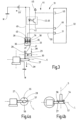
- figure 3 a schematic representation of an embodiment of the electrical connection of a measuring disk with a supply voltage potential and a monitoring device as well as the electrical connection of a measuring mandrel with a reference potential
- Figures 4-7 each a schematic basic representation in a side view (each figure a) and a top view (each figure b) of the measuring mandrel and the measuring disk from the Figures 1-3 with different contact points.
- the grinding and/or eroding machine 10 has a machine axis arrangement 11 which has at least one and preferably a plurality of translatory and/or rotary machine axes 12 .
- the axis arrangement 11 has three translatory axes, namely an X-axis 12x, a Y-axis 12y and a Z-axis 12z.
- the machine axis arrangement 11 has, for example, two rotary machine axes, an A axis 12a and a C axis 12c.
- a rotation about an axis of rotation R running parallel to the y-direction or to the Y-axis 12y can be carried out via the C-axis 12c.
- the A axis can be used to rotate about an axis that extends parallel to the x direction or to the X axis 12x.
- a rotary axis can also be present, with which a rotation around an axis of rotation can be carried out which extends parallel to the z-direction or to the z-axis 12z.
- a tool spindle 13 and/or a tool holding device 14 can be moved relative to a machine base 15 by means of the machine axis arrangement 11, so that a relative movement between the tool spindle 13 and the workpiece holding device 14 can also be achieved.
- Different axis configurations can be used.
- One or more translatory or rotatory machine axes 12 can be used to move the tool spindle 13 and other translatory or rotatory machine axes 12 can be used accordingly to move the workpiece holding device 14 .
- the Y-axis 12y and the Z-axis 12z are used to move the tool spindle 13, while the X-axis 12x and the C-axis 12c are used to move the workpiece holding device 14.
- the A axis 12a is used to drive the workpiece holding device 14 about its longitudinal axis L.
- the machine axles 12 of the axle arrangement 11 are in figure 1 only symbolic and in figure 2 illustrated only by their schematically indicated axes of rotation or carriage.
- the tool spindle 13 is seated on a first carriage 15 which can be moved relative to a second carriage 16 by means of the Y-axis 12y.
- the second carriage 16 carrying the first carriage 15 can be moved relative to the machine base 15 by means of the Z-axis 12z.
- a third carriage 17 is arranged on the machine base 15 so as to be movable via the X-axis 12x and supports the C-axis 12c.
- a carrier 18 can be rotated about an axis of rotation R by means of the C-axis 12c.
- the A-axis 12a and the workpiece holding device 14 are in turn seated on the carrier 18, with the A-axis 12a being able to drive the workpiece holding device 14 about the longitudinal axis L.
- the tool spindle 13 serves to hold a tool 19, for example a grinding tool and/or an eroding tool.
- a tool 19 for example a grinding wheel, can be driven in rotation about the spindle axis S by means of the tool spindle 13 .
- the tool spindle 13 or the associated spindle drive (not shown) is controlled by a control device 21, which can specify a desired speed.
- the workpiece holding device 14 is used to hold or clamp a workpiece 20.
- the workpiece 20 can be rotated or pivoted about the axis of rotation R by means of the A axis 12a about its longitudinal axis L or by means of the C axis 12c.
- the angle between the longitudinal axis L and the spindle axis S is set by a pivoting movement about the axis of rotation R by means of the C-axis 12c. This angle can be varied between 0° and 180°, for example.
- the machine axis arrangement 11 is also controlled via the control device 21 in such a way that each machine axis 12 can be driven individually.
- the position of each machine axis 12 is detected by a position detection device 22 .
- each machine axis 12 can be assigned a position sensor 23 in order to the respective actual position value A is , C is , X is , Y is , Z is to be recorded and transmitted to the control device 21 . If there is a further rotary axis, a corresponding further actual value can also be transmitted from the position detection device 22 to the control device 21, which is shown in figure 1 is illustrated in dashed lines.
- the position can also be detected by the position detection device 22 on the basis of other variables that are characteristic of the respective actual position. A direct measurement of the actual position values is then not necessary.
- the grinding and/or eroding machine 10 is set up to carry out a method for measuring or referencing the machine axes 12 .
- an electrically conductive first measuring body for example a measuring mandrel 27, can be inserted into the workpiece holding device 14 instead of a workpiece.
- an electrically conductive second measuring body for example a measuring disk 28, can be inserted into the tool spindle 13 instead of a tool 19.
- the mandrel 27 is electrically connected to a fixed reference potential and to ground M, for example. The connection can be made via a line directly on the measuring mandrel 27 or indirectly via the workpiece holding device 14 .
- the measuring disk 28 is electrically connected to a supply voltage potential UV.
- a shank section 30 of the shank connected to the measuring disc 28 is electrically insulated from the measuring disc 28 via an electrical insulation 29 .
- the measuring disc 28 is accommodated in the tool spindle 13 via the shank section 30 .
- the supply voltage potential applied to the measuring disc 28 UV is therefore not present at the tool spindle 13 and a flow of current into or through the tool spindle 13 is prevented by the electrical insulation 29 .
- the measuring disk 28 is also electrically connected to a monitoring device 31 .
- the monitoring device 31 has a monitoring unit 32 .
- the monitoring device 31 or at least the monitoring unit 32 can be part of the control device 21 or can be communicatively connected to the control device 21 .
- the electrical connection between the monitoring device 31 and the measuring disc 28 is established via a connecting device with a connecting component 33 and a counter-connecting component 34.
- the connecting component 33 is preferably designed as a plug and the counter-connecting component 34 as a socket.
- the mating connection component 34 can be fastened to the grinding and/or eroding machine 10 in the area of the tool spindle 13, for example to the first carriage 15 or to a carrier for the tool spindle 13 that is connected to the first carriage 15.
- connection portal 33 has at least one electrical first contact 35 and, for example, an additional electrical second contact 36 and an electrical third contact 37.
- the electrical contacts 35, 36, 37 can be designed as plug pins. How it based on figure 3 can be seen, the second contact 36 and the third contact 37 are electrically short-circuited by the connecting component 33 or in the connecting component 33 .
- the mating contact component 34 has at least one electrical first mating contact 38. In the exemplary embodiment, there is also an electrical second mating contact 39 and an electrical third mating contact 40 available.
- the mating contacts 38, 39, 40 can be designed as sockets in order to receive a respectively associated plug pin.
- the first electrical contact 35 is electrically connected to the measuring disk 28 via a connecting line 41 .
- the connection line 41 is formed by a flexible line, for example a spiral cable.
- the first mating contact 38 is connected to the monitoring device 31 by means of a first conductor 42 .
- the first conductor 42 is electrically connected to the supply voltage potential UV via a monitoring component 43 .
- the monitoring component 43 has an electrical switching function and is used to trigger an electrical switching process when a measurement current IM flows through the first conductor 42 . This electrical switching process is detected by the monitoring unit 32 which is electrically connected to the monitoring component 43 .
- the monitoring component 43 also provides galvanic isolation.
- the primary side of the monitoring device 43 is connected in the first conductor 42 while the secondary side of the monitoring device 43 is placed in a secondary circuit 44 .
- the monitoring component 43 is formed by an optocoupler 45 in the exemplary embodiment.
- An optocoupler diode is electrically connected to the supply voltage potential UV on the anode side and to the first mating contact 38 on the cathode side.
- An optocoupler transistor has a secondary voltage potential US and on the collector side electrically connected to a first monitoring input 46 on the emitter side. As soon as a measurement current IM flows through the first conductor 42 and consequently the optocoupler diode, the optocoupler transistor becomes conductive and electrically connects the first monitoring input 46 to the secondary voltage potential US.
- the optocoupler transistor blocks and the secondary voltage potential US is electrically isolated from the first monitoring input 46 .
- the presence of a measurement current IM in the first conductor 42 can thus be detected by the switching process of the optocoupler transistor.
- the secondary circuit 44 can also be electrically constructed differently with the aid of the monitoring component 43 or the optocoupler 45 .
- the first monitoring input 46 can be connected directly to the secondary voltage potential US and to the collector of the optocoupler transistor.
- the emitter of the optocoupler transistor can then be connected via a resistor to a potential which is lower than the secondary voltage potential US, for example a secondary ground potential.
- the secondary ground potential is present at the first monitoring input 46 when a measuring current IM flows through the second conductor 42 on the primary side, while otherwise the optocoupler transistor blocks and the secondary voltage potential US is present at the first monitoring input 46 .
- monitoring device 31 or of the secondary circuit 44 are also possible.
- optocoupler 45 it is also possible to use a relay or another monitoring component 43 which causes a switching process and which can be designed with or without galvanic isolation.
- the second mating contact 39 is electrically connected via a second conductor 49 to the supply voltage potential UV, preferably connected directly.
- the third mating contact 40 is electrically connected to a second monitoring input 51 by means of a third conductor 50, preferably directly.
- an electrical and preferably also a mechanical connection is made between the connecting component 33 and the counter-connecting component 34, an electrical connection is created between the first contact 35 and the first counter-contact 38, between the second contact 36 and the second counter-contact 39 and between the third Contact 37 and the third mating contact 40. Due to the short-circuit connection between the second and the third contact 36, 37, the first conductor 49 is electrically connected to the third conductor 50, as a result of which the supply voltage potential UV is present at the second monitoring input 51.
- the monitoring device 31 or the monitoring unit 32 can determine via the second monitoring input 51 that an electrical connection has been established between the connecting component 33 and the counter-connecting component 34 .
- the monitoring unit 32 is preferably set up to generate a corresponding signal when an electrical connection is detected between the connection component 33 and the mating connection component 34 and to make it available to the control device 21 . This then operates the grinding and/or eroding machine 10 in a safety operating mode. In the safety operating mode, a driving of the tool spindle 13 about the spindle axis S and/or a rotation of the measuring mandrel 27 about the longitudinal axis L is prevented. One inserted into the tool spindle 13 Measuring disk 28 can thereby be prevented from rotating.
- one or more of the machine axes 12 can be operated in the safety operating mode with a force or moment being limited. This prevents excessive forces or moments from acting on the measuring disc 28 or the measuring mandrel 27 when these measuring bodies 27 , 28 come into contact with one another or with another component of the grinding and/or eroding machine 10 .
- the drive torque of a relevant electric motor of the respective machine axis 12 can be limited, for example by a corresponding current limitation of the motor current.
- measuring disc 28 and the measuring mandrel 27 are moved relative to one another via the machine axis arrangement 11 and come into contact with one another at a contact point K, an electrically conductive connection is created between the measuring disc 28 and the measuring mandrel 27 . Due to the potential differences between the supply voltage potential UV present on the measuring disc 28 and the reference potential (ground M) present on the measuring pin 27, a measuring current IM flows, for example from the measuring disc 28 via the measuring pin 27 and on to ground M. This current flow causes switching of the monitoring component 43, so that the monitoring device 31 can detect the current flow of the measurement current IM. At this point in time, a current position of the respective machine axis, which is detected via the position detection device 22, is stored or otherwise registered.
- This arrangement makes it possible without using touch sensors or proximity sensors in the working area of the grinding and/or eroding machine 10 to establish contact between the measuring disk 28 and the measuring mandrel 27 quickly and to be recorded exactly.
- the control device 21 is set up in particular to bring the measuring disc 28 into contact with the measuring mandrel 27 at a predetermined sequence of contact points K.
- the measuring disk 28 preferably has a peripheral surface 54 which forms the edge of the measuring disk 28 and delimits its contour.
- the peripheral surface 54 surrounds a side surface 55 which faces away from the shank section 30 .
- the measuring disc 28 can be brought into contact with the measuring mandrel 27 either with the side surface 55 or with the peripheral surface 54 .
- each approach to a contact point in a predetermined alignment between the longitudinal axis L and the spindle axis S is illustrated schematically.
- a sequence of several contact points K on the measuring mandrel 27 can be approached and the measuring disk 28 can be brought into contact with the measuring mandrel 27 there.
- contact can be established either with the side surface 55 or with the peripheral surface 54 on the measuring disc 28 .
- the contact point K can be present on the lateral surface 56 or the end face 57 of the measuring mandrel 27 .
- the number of contact points K corresponds to the number of machine axes 12 that are set up to move the measuring disk 28 relative to the measuring mandrel 27 .
- there are four machine axes since the A axis 12a can cause the measuring mandrel 27 to rotate about its longitudinal axis L, which, however, does not change the relative position between the measuring disk 28 and the measuring mandrel 27 .
- the mandrel 27 corresponding to the three translational axes 12x, 12y and 12z at three different contact points K in a first position of the C-axis at a approached a predetermined angle of rotation about the axis of rotation R.
- at least one contact point K is approached from a different rotational position of the C axis 12c about the axis of rotation R.
- the two rotational positions about the axis of rotation R can differ from one another by 90°.
- the longitudinal axis L can, for example, first be aligned in the x-direction ( Figures 4-6 ).
- the measuring disk 28 is moved using the Y-axis 12y at a first contact point with the side surface 55 against the lateral surface 56 and the position of this first contact point is recorded ( Figures 4a and 4b ).
- the peripheral surface 54 of the measuring disc 28 is moved against the lateral surface 56 of the measuring mandrel 27 at at least one further contact point K and the position is recorded ( Figures 5a and 5b ).
- the measuring mandrel 27 can be approached along the longitudinal axis L at one or more contact points K by means of the measuring disk 28, for example using the Y-axis 12y. Subsequently, the measuring mandrel 27 can be rotated about the longitudinal axis L by a predetermined angle of rotation and the measuring disc 28 can be approached again at the same point along the longitudinal axis L. In this way, the concentricity of the A-axis 12a can be determined.
- the parallelism of the A axis 12a to the X axis 12x can also be determined. With the help of the X-axis 12x, the measuring mandrel 27 and the measuring disc 28 can be brought into contact at a contact point. The C-axis is then rotated by a predetermined angle of rotation, preferably 180°, and a contact point between the measuring mandrel 27 and the measuring disk 28 is approached again using the X-axis 12x. The axis parallelism can be determined from this. Analogously to this, the parallelism of the A axis 12a to the Z axis 12z can be determined using the Z axis.
- the perpendicularity of the A axis 12a to the Y axis 12y can be determined by traversing several contact points K on the end face 57 of the measuring mandrel 27 with the aid of the Y axis 12y. If the end face 57 is too small for this, a disk electrically connected to the mass M can also be used as the first measuring body instead of the measuring mandrel 27 .
- the axis of rotation R should intersect the longitudinal axis L.
- a center offset between the axis of rotation R and the longitudinal axis L can be determined.
- any further measurements or referencing can be carried out by means of the grinding and/or eroding machine described above.
- a sequence of contact points K can be approached.
- a desired orientation of the longitudinal axis L relative to the spindle axis S can be specified for each contact point. If, in addition to the C-axis 12c explained by way of example, further rotary machine axes are present, their rotary angle positions can also be predetermined for each position detection of a contact point K.
- the measurements or referencing described can also be carried out correspondingly with other axle arrangements. Whether the grinding spindle 13 is moved relative to the machine base 15 or the workpiece holding device 14 is moved relative to the machine base 15 depends on the particular axis arrangement.
- the invention relates to a grinding and/or eroding machine 10 and a method for measuring and referencing the axis arrangement 11 with a plurality of machine axes 12, which can each be formed by a rotary or translatory machine axis.
- a first measuring body (measuring mandrel 27) is inserted into a workpiece holding device 14 and a second measuring body (measuring disk 28) is inserted into a tool spindle 13.
- the measuring mandrel 27 is connected to a reference potential, preferably ground M electrically connected.
- the measuring disc 28 is electrically connected to a supply voltage potential UV.
- a measuring current IM flows between the supply voltage potential UV and the reference potential and, for example, from the supply voltage potential UV to ground M.
- the flow of this measuring current IM can be recorded in a monitoring device 31 and the current position of the machine axes 12 can be determined at the time when the current flow of the measurement current IM begins.
- One or more contact points K between the measuring disc 28 and the measuring mandrel 27 can be approached via the axis arrangement 11 and the axis arrangement 11 or the machine can thereby be referenced or measured.
Description
Die Erfindung betrifft eine Schleif- und/oder Erodiermaschine sowie ein Verfahren zum Vermessen bzw. Referenzieren der Maschine.The invention relates to a grinding and/or eroding machine and a method for measuring or referencing the machine.
Eine Schleif- und/oder Erodiermaschine hat mehrere Maschinenachsen, um ein zu bearbeitendes Werkstück relativ zu einem Werkzeug bewegen und positionieren zu können. Für eine genaue Bearbeitung ist es erforderlich, die Relativposition der Maschinenachsen bezogen auf ein ortsfestes Koordinatensystem der Maschinenbasis oder des Maschinengestells zu kennen.A grinding and/or eroding machine has several machine axes in order to be able to move and position a workpiece to be machined relative to a tool. For precise machining it is necessary to know the relative position of the machine axes in relation to a stationary coordinate system of the machine base or the machine frame.
Das Verwenden von Berührungssensoren oder Kraftsensoren hat muss sichergestellt werden, dass die Kraft, mit der das Werkzeug oder das Werkstück gegen den jeweiligen Referenzsensor gedrückt wird, sehr genau eingestellt werden kann. Die Anforderungen an die Genauigkeit und Konstanz der Sensoren sind damit sehr hoch. Wenn Näherungssensoren verwendet werden, müssen diese sehr genau justiert werden, um einzustellen welche Stelle an dem sich annähernden Element detektiert wird. Alle Sensortypen müssen eine hohe Erfassungsgenauigkeit mit sehr geringer Toleranz aufweisen. Außerdem ist das Verwenden von Berührungs-, Ktraft- oder Näherungssensoren in Werkzeugmaschinen häufig deswegen problematisch, weil sie Verschmutzungen durch Späne, Kühlflüssigkeit oder dergleichen ausgesetzt sind.When using touch sensors or force sensors, it must be ensured that the force with which the tool or workpiece is pressed against the respective reference sensor can be set very precisely. The demands on the accuracy and consistency of the sensors are therefore very high. If proximity sensors are used, these must be adjusted very precisely to set which location on the approaching element is being detected. All sensor types must have high detection accuracy with very low tolerance. In addition, the use of touch, force or proximity sensors in machine tools is often problematic because they are exposed to contamination from chips, coolant or the like.
Es kann daher als Aufgabe der vorliegenden Erfindung angesehen werden, eine Schleif- und/oder Erodiermaschine sowie ein Verfahren zur Vermessung oder Referenzierung der Maschine bereitzustellen, das mit einfachen Mitteln eine hohe Genauigkeit bereitstellt.It can therefore be seen as an object of the present invention to provide a grinding and/or eroding machine and a method for measuring or referencing the machine, which provides a high degree of accuracy using simple means.
Diese Aufgabe wird durch eine Schleif- und/oder Erodiermaschine mit den Merkmalen des Patentanspruches 1 sowie ein Verfahren mit den Merkmalen des Patentanspruches 15 gelöst.This object is achieved by a grinding and/or eroding machine having the features of
Erfindungsgemäß weist die Schleif- und/oder Erodiermaschine eine um eine Spindelachse antreibbare Werkzeugspindel auf, in der ein Schleif- oder Erodierwerkzeug angeordnet werden kann. Für ein zu bearbeitendes Werkstück ist eine Werkstückhalteeinrichtung vorhanden. Die Maschine verfügt über eine Maschinenachsanordnung mit mehreren Maschinenachsen. Jede Maschinenachse kann als rotatorische oder translatorische Maschinenachse ausgeführt sein. Es können bis zu sechs Maschinenachsen vorhanden sein, die dazu eingerichtet sind, die Werkzeugspindel bzw. ein dort vorhandenes Werkzeug relativ zur Werkstückhalteeinrichtung bzw. einem dort angeordneten Werkstück zu positionieren oder zu bewegen, um die gewünschte Bearbeitung durchführen zu können. Über eine Positionserfassungseinrichtung wird die Position jeder der vorhandenen Maschinenachsen erfasst. Die Positionserfassungseinrichtung kann hierfür Positionssensoren aufweisen, die die Position im jeweiligen translatorischen oder rotatorischen Freiheitsgrad messen. Es ist auch möglich, dass die Positionserfassungseinrichtung die Position einer Maschinenachse auf Basis anderer Größen ermittelt, die charakteristisch sind für die jeweilige Position. Es ist daher möglich, dass die Positionserfassung entweder auf Basis von direkt gemessenen Positionsistwerten oder diese Istposition beschreibenden indirekten Größen erfolgt.According to the invention, the grinding and/or eroding machine has a tool spindle that can be driven about a spindle axis and in which a grinding or eroding tool can be arranged. A workpiece holding device is provided for a workpiece to be machined. The machine has a machine axis arrangement with several machine axes. Each machine axis can be designed as a rotary or translatory machine axis. There can be up to six machine axes which are set up to position or move the tool spindle or a tool present there relative to the workpiece holding device or a workpiece arranged there in order to be able to carry out the desired machining. The position of each of the existing machine axes is detected via a position detection device. For this purpose, the position detection device can have position sensors that measure the position in the respective translational or rotational degree of freedom. It is also possible for the position detection device to determine the position of a machine axis on the basis of other variables that are characteristic of the respective position. It is therefore possible for the position to be detected either on the basis of directly measured actual position values or on the basis of indirect variables describing this actual position.
Zum Vermessen oder Referenzieren werden elektrisch leitfähige Messkörper, vorzugsweise ein elektrisch leitfähiger Messdorn sowie eine elektrisch leitfähige Messscheibe verwendet. Der eine, erste Messkörper, insbesondere der Messdorn, kann in der Werkstückhalteeinrichtung angeordnet werden und der jeweils andere, zweite Messkörper, insbesondere die Messscheibe, kann in der Werkzeugspindel angeordnet werden. Zum Vermessen bzw. Referenzieren wird der zweite Messkörper mit einem Versorgungsspannungspotential verbunden, so dass am zweiten Messkörper eine Spannung anliegt, die vorzugsweise dem Versorgungsspannungspotential entspricht. Der in der Werkstückhalteeinrichtung angeordnete erste Messkörper wird mit einem definierten Bezugspotential elektrisch verbunden, das kleiner ist als die Spannung am zweiten Messkörper und beispielsweise kleiner als das Versorgungsspannungspotential. Als Bezugspotential dient vorzugsweise ein Massepotential (0 Volt). Der zweite Messkörper wird außerdem mit einer Überwachungseinrichtung verbunden.Electrically conductive measuring bodies, preferably an electrically conductive measuring mandrel and an electrically conductive measuring disk, are used for measuring or referencing. One, first measuring body, in particular the measuring mandrel, can be arranged in the workpiece holding device and the respective other, second measuring body, in particular the measuring disk, can be arranged in the tool spindle. For measuring or referencing, the second measuring body is connected to a supply voltage potential, so that a voltage which preferably corresponds to the supply voltage potential is present at the second measuring body. The first measuring body arranged in the workpiece holding device is electrically connected to a defined reference potential which is lower than the voltage on the second measuring body and, for example, smaller than the supply voltage potential. A ground potential (0 volts) is preferably used as the reference potential. The second measuring body is also connected to a monitoring device.
Über eine Steuereinrichtung können die Messkörper relativ zueinander bewegt bzw. positioniert bzw. ausgerichtet werden. Die Steuereinrichtung der Maschine steuert die Maschinenachsen an, um die Messkörper derart relativ zueinander zu bewegen, dass sie an einer Kontaktstelle in Kontakt miteinander gelangen. Sobald dieser Kontakt an der Kontaktstelle entsteht, fließt ein Messstrom zwischen der den Messkörpern und vorzugsweise vom zweiten Messkörper mit höherem Potential zum ersten Messkörper mit geringerem Potential. Dieser Messstrom wird durch die mit dem zweiten Messkörper verbundene Überwachungseinrichtung erkannt. Sobald der Messstrom erkannt wird, wird die aktuelle Position der wenigstens einen angetriebenen Maschinenachse bzw. aller Maschinenachsen abgespeichert. Somit kann durch das Berühren zwischen den Messkörpern an der Kontaktstelle eine Referenzposition ermittelt werden. Das Ermitteln dieser Referenzposition kann sehr exakt erfolgen. Es hat sich gezeigt, dass der Messstrom sehr genau unmittelbar nach einer Berührung zwischen den Messkörpern erfasst werden kann. Zu diesem Zeitpunkt kann die entsprechende aktuelle Position als Referenzposition erfasst bzw. gespeichert werden. Unterschiede durch variierende Andrückkräfte zwischen den Messkörpern treten nicht auf.The measuring bodies can be moved or positioned or aligned relative to one another via a control device. The control device of the machine controls the machine axes in order to move the measuring bodies relative to one another in such a way that they come into contact with one another at a contact point. As soon as this contact occurs at the contact point, a measuring current flows between the measuring bodies and preferably from the second measuring body with a higher potential to the first measuring body with a lower potential. This measuring current is detected by the monitoring device connected to the second measuring body. As soon as the measuring current is detected, the current position of the at least one driven machine axis or of all machine axes is stored. A reference position can thus be determined by touching between the measuring bodies at the contact point. This reference position can be determined very precisely. It has been shown that the measuring current can be recorded very precisely immediately after contact between the measuring bodies. At this point in time, the corresponding current position can be recorded or stored as a reference position. Differences due to varying contact forces between the measuring bodies do not occur.
Die Maschine bzw. das Verfahren kommt ohne aufwendige Sensorik aus. Die Erfassung des Messstromes kann außerhalb des Arbeitsbereiches der Maschine erfolgen. Empfindliche Sensoren innerhalb des Arbeitsbereichs der Maschine entfallen. Somit kann die Referenzierung bzw. Vermessung mit einfachen, kostengünstigen Mitteln bei gleichzeitig hoher Genauigkeit durchgeführt werden.The machine or the process does not require complex sensors. The measuring current can be recorded outside the working area of the machine. There are no sensitive sensors within the working area of the machine. Thus, the referencing or Measurement can be carried out with simple, inexpensive means with high accuracy at the same time.
Vorzugsweise wird das Antreiben der wenigstens eine angetriebene Maschinenachse gestoppt, sobald die Berührung zwischen den Messkörpern festgestellt wurde. Dadurch werden große Andrückkräfte zwischen den Messkörpern vermieden.The driving of the at least one driven machine axis is preferably stopped as soon as contact between the measuring bodies has been established. This avoids large pressing forces between the measuring bodies.
Zur Vermessung bzw. Referenzierung wird eine Folge von Kontaktstellen nacheinander angefahren. Es sind zumindest zwei, drei oder mehr Kontaktstellen pro Folge vorhanden, um eine bestimmte Vermessung durchzuführen oder die Orientierung zwischen Maschinenachsen miteinander zu vergleichen. Dabei wird für die wenigstens eine Kontaktstelle eine Orientierung für eine oder mehrere rotatorische Maschinenachsen vorgegeben. Die Anfahrbewegung unmittelbar vor der und bis zur Berührung zwischen den Messkörpern erfolgt bevorzugt durch eine einzige, insbesondere translatorische Maschinenachse.For measurement or referencing, a sequence of contact points is approached one after the other. There are at least two, three or more contact points per sequence to perform a particular measurement or to compare orientation between machine axes. In this case, an orientation for one or more rotary machine axes is specified for the at least one contact point. The approach movement immediately before and up to the point of contact between the measuring bodies is preferably carried out by a single, in particular translatory, machine axis.
Der zweite Messkörper kann bei einem bevorzugten Ausführungsbeispiel als Messscheibe ausgeführt sein, die eine ringförmig geschlossene Umfangsfläche und eine Seitenfläche aufweist, wobei die die Umfangsfläche die Seitenfläche umschließt und sich daran anschließt. Beispielsweise kann die Messscheibe durch eine kreisförmig konturierte Scheibe gebildet sein. Es ist dabei möglich, dass die Messscheibe den anderen, ersten Messkörper mit der Umfangsfläche oder der Seitenfläche an der Kontaktstelle berührt. Dies hängt davon ab, wo die Kontaktstelle am ersten Messkörper, beispielsweise dem Messdorn, angeordnet ist und welche der Maschinenachsen zur Relativbewegung bis zum Erreichen dieser Kontaktstelle verwendet wird.In a preferred exemplary embodiment, the second measuring body can be designed as a measuring disk, which has an annularly closed peripheral surface and a side surface, the peripheral surface enclosing the side surface and adjoining it. For example, the measuring disk can be formed by a circularly contoured disk. It is possible that the measuring disk touches the other, first measuring body with the peripheral surface or the side surface at the contact point. This depends on where the contact point on the first measuring body, for example the measuring mandrel, is arranged and which of the machine axes is used for the relative movement until this contact point is reached.
Um ein Vermessen bzw. Referenzieren aller Maschinenachsen der Schleif- und/oder Erodiermaschine vorzunehmen, entspricht die Anzahl der in einer Folge nacheinander angefahrenen Kontaktstellen vorzugsweise der Anzahl von denjenigen Maschinenachsen, die dazu eingerichtet sind, die Relativposition zwischen den Messkörpern zu ändern. Dabei wird eine Maschinenachse nicht berücksichtigt, die eine Drehung des ersten Messkörpers um seine Längsachse bewirken kann.In order to measure or reference all machine axes of the grinding and/or eroding machine, the number of contact points approached in succession preferably corresponds to the number of those machine axes that are set up to change the relative position between the measuring bodies. A machine axis that can cause the first measuring body to rotate about its longitudinal axis is not taken into account.
Bei einem bevorzugten Ausführungsbeispiel weist die Überwachungseinrichtung eine Überwachungseinheit auf. Die Überwachungseinheit kann Bestandteil der Steuereinrichtung sein oder mit der Steuereinrichtung kommunikationsverbunden sein.In a preferred embodiment, the monitoring device has a monitoring unit. The monitoring unit can be part of the control device or can be communicatively connected to the control device.
Die Überwachungseinheit ist vorzugsweise dazu eingerichtet zu überwachen, ob der zweite Messkörper mit dem Versorgungsspannungspotential elektrisch verbunden ist. Ein entsprechendes Überwachungsergebnis kann zur Steuereinrichtung übermittelt oder der Steuereinrichtung auf andere geeignete Weise bereitgestellt werden. Die Steuereinrichtung kann in einen Sicherheitsbetriebsmodus umschalten, wenn die Überwachungseinheit festgestellt hat, dass die elektrische Verbindung zwischen dem zweiten Messkörper und dem Versorgungsspannungspotential hergestellt ist. Dadurch wird sozusagen erkannt, dass keine Werkstückbearbeitung, sondern eine Vermessung bzw. Referenzierung durchgeführt werden soll. Daraufhin wird der Sicherheitsbetriebsmodus aktiviert und die Steuereinrichtung steuert die Maschinenachsanordnung unter Einhaltung wenigstens einer Beschränkung des Sicherheitsbetriebsmodus an.The monitoring unit is preferably set up to monitor whether the second measuring body is electrically connected to the supply voltage potential. A corresponding monitoring result can be transmitted to the control device or made available to the control device in some other suitable way. The control device can switch to a safety operating mode when the monitoring unit has determined that the electrical connection between the second measuring body and the supply voltage potential has been established. As a result, it is recognized, so to speak, that no workpiece machining is to be carried out, but rather a measurement or referencing. The safety operating mode is then activated and the control device controls the machine axis arrangement while maintaining at least one limitation of the safety operating mode.
In dem Sicherheitsbetriebsmodus kann beispielsweise das Betreiben der Werkzeugspindel unterbunden werden, so dass verhindert wird, dass sich der zweite Messkörper um die Spindelachse dreht. Alternativ oder zusätzlich kann die Antriebskraft bzw. ein Antriebsmoment einer oder mehrerer Maschinenachsen auf eine Maximalkraft bzw. ein Maximaldrehmoment begrenzt werden. Dadurch können Beschädigungen an den Messkörpern durch zu große Andrückkräfte vermieden werden. Hierfür kann beispielsweise ein Elektromotor, der zur jeweiligen Maschinenachse gehört und deren Antrieb bildet, einer Drehmomentbegrenzung unterworfen werden, beispielsweise durch eine entsprechende Begrenzung des Motorstromes. Zur Kraft- oder Momentenbegrenzung der jeweiligen Maschinenachse kann beispielsweise eine Messung und Begrenzung des Motorstromes erfolgen.In the security mode of operation, for example the operation of the tool spindle can be prevented, so that it is prevented that the second measuring body rotates about the spindle axis. Alternatively or additionally, the driving force or a driving torque of one or more machine axes can be limited to a maximum force or a maximum torque. As a result, damage to the measuring bodies due to excessive pressure forces can be avoided. For this purpose, for example, an electric motor that belongs to the respective machine axis and forms its drive can be subjected to a torque limitation, for example by a corresponding limitation of the motor current. For example, the motor current can be measured and limited to limit the force or torque of the respective machine axis.
Es ist vorteilhaft, wenn der zweite Messkörper über eine Anschlussleitung mit einem ersten Kontakt eines elektrischen Verbindungsbauteils elektrisch verbunden ist. Das elektrische Verbindungsbauteil kann außerdem einen zweiten Kontakt und einen dritten Kontakt aufweisen, die miteinander kurzgeschlossen sein können.It is advantageous if the second measuring body is electrically connected to a first contact of an electrical connection component via a connecting line. The electrical connection component may also include a second contact and a third contact that may be shorted together.
Zur elektrischen Verbindung mit dem Verbindungsbauteil kann ein elektrisches Gegenverbindungsbauteil vorhanden sein. Das Gegenverbindungsbauteil hat einen ersten Gegenkontakt, der mittels eines ersten Leiters über die Überwachungseinrichtung mit dem Versorgungsspannungspotential verbunden ist. In diesem ersten Leiter kann ein Überwachungsbauteil der Überwachungseinrichtung angeordnet sein, das eine Schaltfunktion bereitstellt, beispielsweise ein Transistor, ein Relais, ein Optokoppler oder dergleichen. Das Überwachungsbauteil kann vorzugsweise außerdem eine galvanische Trennung des ersten Leiters von einem Messschaltkreis bereitstellen.An electrical mating connection component can be present for the electrical connection to the connection component. The mating connection component has a first mating contact, which is connected to the supply voltage potential by means of a first conductor via the monitoring device. A monitoring component of the monitoring device which provides a switching function, for example a transistor, a relay, an optocoupler or the like, can be arranged in this first conductor. The monitoring component can preferably also provide galvanic isolation of the first conductor from a measuring circuit.
Es ist außerdem vorteilhaft, wenn das Gegenverbindungsbauteil einen zweiten Gegenkontakt aufweist, der mittels eines zweiten Leiters mit dem Versorgungsspannungspotential verbunden ist. Zusätzlich kann optional ein dritter Gegenkontakt vorhanden sein, der mittels eines dritten Leiters mit der Überwachungseinrichtung und insbesondere der Überwachungseinheit der Überwachungseinrichtung verbunden ist.It is also advantageous if the mating connection component has a second mating contact which is connected to the supply voltage potential by means of a second conductor. In addition, a third counter-contact can optionally be present, which is connected to the monitoring device and in particular to the monitoring unit of the monitoring device by means of a third conductor.
Bei hergestellter Verbindung zwischen dem Verbindungsbauteil und dem Gegenverbindungsbauteil ist eine elektrische Verbindung zwischen dem ersten Kontakt und dem ersten Gegenkontakt hergestellt. Sofern vorhanden, wird dabei auch eine elektrische Verbindung zwischen dem zweiten Kontakt und dem zweiten Gegenkontakt und/oder zwischen dem dritten Kontakt und dem dritten Gegenkontakt hergestellt. Aufgrund des Kurzschlusses zwischen dem zweiten und dritten Kontakt wird somit bei hergestellter Verbindung zwischen dem Verbindungsbauteil und dem Gegenverbindungsbauteil eine elektrische Verbindung zwischen dem Versorgungsspannungspotential und der Überwachungseinrichtung bzw. der Überwachungseinheit hergestellt. Auf diese Weise kann das Verbinden des zweiten Messkörpers mit dem Versorgungsspannungspotential erkannt und beispielsweise der Sicherheitsbetriebsmodus aktiviert werden.When the connection is established between the connecting component and the mating connection component, an electrical connection is established between the first contact and the first mating contact. If present, an electrical connection is also established between the second contact and the second counter-contact and/or between the third contact and the third counter-contact. Because of the short circuit between the second and third contacts, an electrical connection is established between the supply voltage potential and the monitoring device or the monitoring unit when the connection is established between the connecting component and the mating connection component. In this way, the connection of the second measuring body to the supply voltage potential can be recognized and, for example, the safety operating mode can be activated.
Vorteilhafte Ausgestaltungen der Erfindung ergeben sich aus den abhängigen Patentansprüchen, der Beschreibung und der Zeichnung. Nachfolgend werden bevorzugte Ausführungsbeispiele der Erfindung anhand der beigefügten Zeichnungen im Einzelnen erläutert. Es zeigen:Advantageous refinements of the invention result from the dependent patent claims, the description and the drawing. Preferred exemplary embodiments of the invention are explained in detail below with reference to the attached drawings. Show it:
In den
Mittels der Maschinenachsanordnung 11 kann eine Werkzeugspindel 13 und/oder eine Werkzeughalteeinrichtung 14 relativ zu einer Maschinenbasis 15 bewegt werden, so dass auch eine Relativbewegung zwischen der Werkzeugspindel 13 und der Werkstückhalteeinrichtung 14 erreichbar ist. Dabei können unterschiedliche Achskonfigurationen verwendet werden. Zur Bewegung der Werkzeugspindel 13 können eine oder mehrere translatorische oder rotatorische Maschinenachsen 12 und zur Bewegung der Werkstückhalteeinrichtung 14 entsprechend andere translatorische bzw. rotatorische Maschinenachsen 12 verwendet werden. Bei dem in
Die Maschinenachsen 12 der Achsanordnung 11 sind in
Somit kann mittels der Maschinenachsanordnung 11 eine Ausrichtung bzw. Positionierung der Werkzeugspindel 13 relativ zur Werkstückhalteeinrichtung 14 durchgeführt werden. Die Werkzeugspindel 13 dient zur Aufnahme eines Werkzeugs 19, beispielsweise eines Schleifwerkzeugs und/oder eines Erodierwerkzeugs. Mittels der Werkzeugspindel 13 ist ein Werkzeug 19, wie beispielsweise eine Schleifscheibe, um die Spindelachse S drehend antreibbar. Die Werkzeugspindel 13 bzw. der dazugehörende Spindelantrieb (nicht veranschaulicht) wird durch eine Steuereinrichtung 21 angesteuert, die eine gewünschte Drehzahl vorgeben kann.An alignment or positioning of the
Die Werkstückhalteeinrichtung 14 dient zum Aufnehmen bzw. Spannen eines Werkstücks 20. Das Werkstück 20 kann mittels der die A-Achse 12a um seine Längsachse L oder mittels der die C-Achse 12c um die Rotationsachse R gedreht bzw. geschwenkt werden. Durch eine Schwenkbewegung um die Rotationsachse R mittels der C-Achse 12c wird der Winkel zwischen der Längsachse L und der Spindelachse S eingestellt. Dieser Winkel kann einen beispielsgemäß zwischen 0° und 180° variiert werden.The
Über die Steuereinrichtung 21 wird auch die Maschinenachsanordnung 11 derart angesteuert, dass jede Maschinenachse 12 individuell antreibbar ist. Die Position jeder Maschinenachse 12 wird durch eine Positionserfassungseinrichtung 22 erfasst. Dabei kann jeder Maschinenachse 12 jeweils ein Positionssensor 23 zugeordnet sein, um den jeweiligen Positionsistwert Aist, Cist, Xist, Yist, Zist zu erfassen und an die Steuereinrichtung 21 zu übermitteln. Wenn eine weitere rotative Achse vorhanden ist, kann auch ein entsprechender weiterer Istwert von der Positionserfassungseinrichtung 22 an die Steuereinrichtung 21 übermittelt werden, was in
Alternativ zu der vorgeschlagenen Ausführungsform, kann die Positionserfassung durch die Positionserfassungseinrichtung 22 auch auf Basis von anderen Größen erfolgen, die charakteristisch sind für die jeweilige Istposition. Eine direkte Messung der Positionsistwerte ist dann nicht erforderlich.As an alternative to the proposed embodiment, the position can also be detected by the
Die Schleif- und/oder Erodiermaschine 10 ist beispielsgemäß zur Durchführung eines Verfahrens zum Vermessen oder Referenzieren der Maschinenachsen 12 eingerichtet. Hierzu kann anstelle eins Werkstücks ein elektrisch leitfähiger erster Messkörper, beispielsgemäß ein Messdorn 27, in die Werkstückhalteeinrichtung 14 eingesetzt werden. Außerdem kann ein elektrisch leitfähiger zweiter Messkörper, beispielsgemäß eine Messscheibe 28, in die Werkzeugspindel 13 anstelle eines Werkzeugs 19 eingesetzt werden. Der Messdorn 27 ist mit einem festen Bezugspotential und beispielsgemäß mit Masse M elektrisch verbunden. Die Verbindung kann über eine Leitung unmittelbar am Messdorn 27 oder mittelbar über die Werkstückhalteeinrichtung 14 erfolgen.According to the example, the grinding and/or eroding
Die Messscheibe 28 ist elektrisch mit einem Versorgungsspannungspotential UV verbunden. Über eine elektrische Isolation 29 ist ein Schaftabschnitt 30 des mit der Messscheibe 28 verbundenen Schafts gegenüber der Messscheibe 28 elektrisch isoliert. Über den Schaftabschnitt 30 wird die Messscheibe 28 in der Werkzeugspindel 13 aufgenommen. Das an der Messscheibe 28 anliegende Versorgungsspannungspotential UV liegt daher nicht an der Werkzeugspindel 13 an und ein Stromfluss in oder über die Werkzeugspindel 13 ist durch die elektrische Isolation 29 vermieden.The measuring
Die Messscheibe 28 ist außerdem elektrisch mit einer Überwachungseinrichtung 31 verbunden. Die Überwachungseinrichtung 31 weist eine Überwachungseinheit 32 auf. Die Überwachungseinrichtung 31 oder zumindest die Überwachungseinheit 32 kann Bestandteil der Steuereinrichtung 21 sein oder mit der Steuereinrichtung 21 kommunikationsverbunden sein. Die elektrische Verbindung zwischen der Überwachungseinrichtung 31 und der Messscheibe 28 erfolgt über eine Verbindungseinrichtung mit einem Verbindungsbauteil 33 und einem Gegenverbindungsbauteil 34. Das Verbindungsbauteil 33 ist vorzugsweise als Stecker und das Gegenverbindungsbauteil 34 als Buchse ausgeführt. Das Gegenverbindungsbauteil 34 kann beispielsweise im Bereich der Werkzeugspindel 13 an der Schleif- und/oder Erodiermaschine 10 befestigt sein, beispielsweise am ersten Schlitten 15 oder eine mit dem ersten Schlitten 15 verbundenen Träger für die Werkzeugspindel 13.The measuring
Das Verbindungsportal 33 hat beim Ausführungsbeispiel wenigstens einen elektrischen ersten Kontakt 35 und beispielsgemäß zusätzlich einen elektrischen zweiten Kontakt 36 und einen elektrischen dritten Kontakt 37. Die elektrischen Kontakte 35, 36, 37 können als Steckerstifte ausgeführt sein. Wie es anhand von
Das Gegenkontaktbauteil 34 hat zumindest einen elektrischen ersten Gegenkontakt 38. Beim Ausführungsbeispiel sind zusätzlich ein elektrischer zweiter Gegenkontakt 39 und ein elektrischer dritter Gegenkontakt 40 vorhanden. Die Gegenkontakte 38, 39, 40 können als Buchsen ausgeführt sein, um einen jeweils zugeordneten Steckerstift aufzunehmen.The
Der erste elektrische Kontakt 35 ist über eine Anschlussleitung 41 elektrisch mit der Messscheibe 28 verbunden. Die Anschlussleitung 41 ist durch eine flexible Leitung, beispielsweise ein Spiralkabel gebildet.The first
Der erste Gegenkontakt 38 ist mittels eines ersten Leiters 42 mit der Überwachungseinrichtung 31 verbunden. Beim Ausführungsbeispiel ist der erste Leiter 42 über ein Überwachungsbauteil 43 mit dem Versorgungsspannungspotential UV elektrisch verbunden. Das Überwachungsbauteil 43 hat eine elektrische Schaltfunktion und dient dazu, einen elektrischen Schaltvorgang auszulösen, wenn ein Messstrom IM durch den ersten Leiter 42 fließt. Dieser elektrische Schaltvorgang wird von der Überwachungseinheit 32 erfasst, die mit dem Überwachungsbauteil 43 elektrisch verbunden ist.The
Bei dem hier beschriebenen Ausführungsbeispiel stellt das Überwachungsbauteil 43 außerdem eine galvanische Trennung bereit. Die primäre Seite des Überwachungsbauteils 43 ist in den ersten Leiter 42 geschaltet, während die sekundäre Seite des Überwachungsbauteils 43 in einem Sekundärschaltkreis 44 angeordnet ist.In the exemplary embodiment described here, the monitoring component 43 also provides galvanic isolation. The primary side of the monitoring device 43 is connected in the
Das Überwachungsbauteil 43 ist beim Ausführungsbeispiel durch einen Optokoppler 45 gebildet. Eine Optokopplerdiode ist anodenseitig mit dem Versorgungsspannungspotential UV und kathodenseitig mit dem ersten Gegenkontakt 38 elektrisch verbunden. Ein Optokopplertransistor ist kollektorseitig mit einem Sekundärspannungspotential US und emitterseitig mit einem ersten Überwachungseingang 46 elektrisch verbunden. Sobald ein Messstrom IM durch den ersten Leiter 42 und mithin die Optokopplerdiode fließt, wird der Optokopplertransistor leitend und verbindet den ersten Überwachungseingang 46 elektrisch mit dem Sekundärspannungspotential US. Fließt hingegen kein Messstrom IM durch die Optokopplerdiode, sperrt der Optokopplertransistor und das Sekundärspannungspotential US ist elektrisch vom ersten Überwachungseingang 46 getrennt. Durch den Schaltvorgang des Optokopplertransistors kann somit das Vorhandensein eines Messstromes IM im ersten Leiter 42 erfasst werden.The monitoring component 43 is formed by an optocoupler 45 in the exemplary embodiment. An optocoupler diode is electrically connected to the supply voltage potential UV on the anode side and to the
Der Sekundärschaltkreis 44 kann mit Hilfe des Überwachungsbauteils 43 oder des Optokopplers 45 elektrisch auch anders aufgebaut werden. Beispielsweise kann der erste Überwachungseingang 46 unmittelbar mit dem Sekundärspannungspotential US und mit dem Kollektor des Optokopplertransistors verbunden werden. Der Emitter des Optokopplertransistors kann dann über einen Widerstand mit einem gegenüber dem Sekundärspannungspotential US geringeren Potential, beispielsweise einem sekundären Massepotential verbunden werden. In diesem Fall liegt das sekundäre Massepotential am ersten Überwachungseingang 46 an, wenn primärseitig ein Messstrom IM durch den zweiten Leiter 42 fließt, während ansonsten der Optokopplertransistor sperrt und am ersten Überwachungseingang 46 das Sekundärspannungspotential US anliegt.The
Auch weitere Abwandlungen der Überwachungseinrichtung 31 bzw. des Sekundärschaltkreises 44 sind möglich. Anstelle des Optokopplers 45 kann auch ein Relais oder ein anderes, einen Schaltvorgang verursachendes Überwachungsbauteil 43 verwendet werden, das mit oder ohne galvanischer Trennung ausgebildet sein kann.Further modifications of the
Der zweite Gegenkontakt 39 ist elektrisch über einen zweiten Leiter 49 mit dem Versorgungsspannungspotential UV verbunden, vorzugsweise unmittelbar verbunden. Der dritte Gegenkontakt 40 ist mittels eines dritten Leiters 50 elektrisch mit einem zweiten Überwachungseingang 51 elektrisch verbunden, vorzugsweise unmittelbar.The
Wenn eine elektrische und vorzugsweise auch eine mechanische Verbindung zwischen dem Verbindungsbauteil 33 und dem Gegenverbindungsbauteil 34 hergestellt wird, entsteht jeweils eine elektrische Verbindung zwischen dem ersten Kontakt 35 und dem ersten Gegenkontakt 38, zwischen dem zweiten Kontakt 36 und dem zweiten Gegenkontakt 39 und zwischen dem dritten Kontakt 37 und dem dritten Gegenkontakt 40. Aufgrund der Kurzschlussverbindung zwischen dem zweiten und dem dritten Kontakt 36, 37, ist der erste Leiter 49 mit dem dritten Leiter 50 elektrisch verbunden, wodurch das Versorgungsspannungspotential UV am zweiten Überwachungseingang 51 anliegt. Über den zweiten Überwachungseingang 51 kann die Überwachungseinrichtung 31 bzw. die Überwachungseinheit 32 feststellen, dass eine elektrische Verbindung zwischen dem Verbindungsbauteil 33 und dem Gegenverbindungsbauteil 34 hergestellt wurde.If an electrical and preferably also a mechanical connection is made between the connecting
Vorzugsweise ist die Überwachungseinheit 32 dazu eingerichtet, bei erkannter elektrischer Verbindung zwischen dem Verbindungsbauteil 33 und dem Gegenverbindungsbauteil 34 ein entsprechendes Signal zu erzeugen und der Steuereinrichtung 21 bereitzustellen. Diese betreibt die Schleif- und/oder Erodiermaschine 10 dann in einem Sicherheitsbetriebsmodus. Im Sicherheitsbetriebsmodus wird ein Antreiben der Werkzeugspindel 13 um die Spindelachse S und/oder eine Drehung des Messdorns 27 um die Längsachse L verhindert. Eine in die Werkzeugspindel 13 eingesetzte Messscheibe 28 kann dadurch am Rotieren gehindert werden.The
Alternativ oder zusätzlich können eine oder mehrere der Maschinenachsen 12 im Sicherheitsbetriebsmodus unter Begrenzung einer Kraft bzw. eines Moments betrieben werden. Dadurch wird verhindert, dass zu große Kräfte oder Momente auf die Messscheibe 28 oder den Messdorn 27 wirken, wenn diese Messkörper 27, 28 miteinander oder mit einem anderen Bauteil der Schleif- und/oder Erodiermaschine 10 in Kontakt gelangen. Hierzu kann beispielsweise das Antriebsmoment eines betreffenden Elektromotors der jeweiligen Maschinenachse 12 begrenzt werden, beispielsweise durch eine entsprechende Strombegrenzung des Motorstromes.Alternatively or additionally, one or more of the machine axes 12 can be operated in the safety operating mode with a force or moment being limited. This prevents excessive forces or moments from acting on the
Wenn über die Maschinenachsanordnung 11 die Messscheibe 28 und der Messdorn 27 relativ zueinander bewegt werden und an einer Kontaktstelle K miteinander in Kontakt gelangen, entsteht zwischen der Messscheibe 28 und dem Messdorn 27 eine elektrisch leitende Verbindung. Aufgrund der Potenzialunterschiede zwischen dem an der Messscheibe 28 anliegenden Versorgungsspannungspotential UV und dem an dem Messdorn 27 anliegenden Bezugspotenzial (Masse M), fließt ein Messstrom IM, beispielsgemäß von der Messscheibe 28 über den Messdorn 27 und weiter zur Masse M. Dieser Stromfluss verursacht ein Schalten des Überwachungsbauteils 43, so dass die Überwachungseinrichtung 31 den Stromfluss des Messstromes IM erfassen kann. Zu diesem Zeitpunkt wird eine aktuelle Position der jeweiligen Maschinenachse, die über die Positionserfassungseinrichtung 22 erfasst wird, gespeichert oder anderweitig registriert.If the
Dieser Anordnung ist es ohne Verwendung von Berührungssensoren oder Näherungssensoren im Arbeitsraum der Schleif- und/oder Erodiermaschine 10 möglich, einen Kontakt zwischen der Messscheibe 28 und dem Messdorn 27 schnell und exakt zu erfassen.This arrangement makes it possible without using touch sensors or proximity sensors in the working area of the grinding and/or eroding
Die Steuereinrichtung 21 ist insbesondere dazu eingerichtet, die Messscheibe 28 an einer vorgegebenen Folge von Kontaktstellen K mit dem Messdorn 27 in Kontakt zu bringen. Die Messscheibe 28 weist vorzugsweise eine Umfangsfläche 54 auf, die den Rand der Messscheibe 28 bildet und deren Kontur begrenzt. Die Umfangsfläche 54 umgibt eine Seitenfläche 55, die von dem Schaftabschnitt 30 abgewandt ist. Die Messscheibe 28 kann entweder mit der Seitenfläche 55 oder mit der Umfangsfläche 54 in Kontakt mit dem Messdorn 27 gebracht werden.The
In den
Die Anzahl der Kontaktstellen K entspricht der Anzahl der Maschinenachsen 12, die dazu eingerichtet sind, die Messscheibe 28 relativ zu dem Messdorn 27 zu bewegen. Beispielsgemäß sind dies vier Maschinenachsen, da die A-Achse 12a eine Rotation des Messdorns 27 um seine Längsachse L verursachen kann, was jedoch die Relativposition zwischen der Messscheibe 28 und dem Messdorn 27 nicht ändert. Somit wird der Messdorn 27 entsprechend der drei translatorischen Achsen 12x, 12y und 12z an drei verschiedenen Kontaktstellen K in einer ersten Stellung der C-Achse bei einem vorgegebenen Drehwinkel um die Rotationsachse R angefahren. Zusätzlich wird wenigstens eine Kontaktstelle K unter einer anderen Drehstellung der C-Achse 12c um die Rotationsachse R angefahren. Beispielsweise können die beiden Drehstellungen um die Rotationsachse R um 90° voneinander verschieden sein.The number of contact points K corresponds to the number of machine axes 12 that are set up to move the
Beim Ausführungsbeispiel kann die Längsachse L zum Beispiel zunächst in x-Richtung ausgerichtet werden (
Mit Hilfe der beschriebenen Schleif- und/oder Erodiermaschine 10 kann eine Vielzahl von geometrischen Messungen durchgeführt werden. Beispielsweise kann der Messdorn 27 entlang der Längsachse L an einer oder mehreren Kontaktstellen K mittels der Messcheibe 28 angefahren werden, beispielsweise unter Verwendung der Y-Achse 12y. Anschließend kann der Messdorn 27 um einen vorgegebenen Drehwinkelbetrag um die Längsachse L gedreht und an derselben Stelle entlang der Längsachse L erneut durch die Messscheibe 28 angefahren werden. Auf diese Weise kann der Rundlauf der A-Achse 12a ermittelt werden.A large number of geometric measurements can be carried out with the aid of the described grinding and/or eroding
Auch die Parallelität der A-Achse 12a zur X-Achse 12x kann ermittelt werden. Mit Hilfe der X-Achse 12x können der Messdorn 27 und die Messscheibe 28 an einer Kontaktstelle in Kontakt gebracht werden. Anschließend wird die C-Achse um einen vorgegebenen Drehwinkelbetrag, vorzugsweise 180° gedreht und es wird erneut unter Verwendung der X-Achse 12x eine Kontaktstelle zwischen dem Messdorn 27 und der Messscheibe 28 angefahren. Daraus kann die Achsparallelität ermittelt werden. Analog hierzu kann unter Verwendung der Z-Achse die Parallelität der A-Achse 12a zur Z-Achse 12z ermittelt werden.The parallelism of the
Durch Abfahren von mehreren Kontaktstellen K an der Stirnfläche 57 des Messdorns 27 mit Hilfe der Y-Achse 12y kann beispielsweise die Rechtwinkligkeit der A-Achse 12a zur Y-Achse 12y ermittelt werden. Wenn die Stirnfläche 57 hierfür zu klein ist, kann anstelle des Messdorns 27 auch eine mit der Masse M elektrisch verbundene Scheibe als erster Messkörper verwendet werden.For example, the perpendicularity of the
Wenn die A-Achse 12a parallel zur X-Achse 12x ausgerichtet ist, soll die Rotationsachse R die Längsachse L schneiden. Durch Anfahren einer Kontaktstelle K am Schnittpunkt zwischen der Rotationsachse R und der Mantelfläche 56 des Messdorns 27 in unterschiedlichen Dreh- bzw. Schwenkstellungen um die Rotationsachse R kann ein Mittenversatz zwischen der Rotationsachse R und der Längsachse L festgestellt werden.When the A-axis 12a is aligned parallel to the X-axis 12x is, the axis of rotation R should intersect the longitudinal axis L. By approaching a contact point K at the intersection between the axis of rotation R and the
Mittels der vorstehend beschriebenen Schleif- und/oder Erodiermaschine lassen sich beliebige weitere Vermessungen bzw. Referenzierungen ausführen. Hierzu kann jeweils eine Folge von Kontaktstellen K angefahren werden. Für jede Kontaktstelle kann eine gewünschte Orientierung der Längsachse L relativ zu der Spindelachse S vorgegeben werden. Wenn zusätzlich zu der beispielsgemäß erläuterten C-Achse 12c weitere rotatorische Maschinenachsen vorhanden sind, können auch deren Drehwinkelstellungen für jede Positionserfassung einer Kontaktstelle K vorgegeben sein.Any further measurements or referencing can be carried out by means of the grinding and/or eroding machine described above. For this purpose, a sequence of contact points K can be approached. A desired orientation of the longitudinal axis L relative to the spindle axis S can be specified for each contact point. If, in addition to the C-
Die beschriebenen Vermessungen bzw. Referenzierungen können auch bei anderen Achsanordnungen entsprechend erfolgen. Ob dabei die Schleifspindel 13 relativ zur Maschinenbasis 15 oder die Werkstückhalteeinrichtung 14 relativ zur Maschinenbasis 15 bewegt wird, hängt von der jeweiligen konkreten Achsanordnung ab.The measurements or referencing described can also be carried out correspondingly with other axle arrangements. Whether the grinding
Die Erfindung betrifft eine Schleif- und/oder Erodiermaschine 10 sowie ein Verfahren zur Vermessung und Referenzierung der Achsanordnung 11 mit mehreren Maschinenachsen 12, die jeweils durch eine rotatorische oder translatorische Maschinenachse gebildet sein können. Hierzu wird ein erster Messkörper (Messdorn 27) in eine Werkstückhalteeinrichtung 14 und ein zweiter Messkörper (Messscheibe 28) in eine Werkzeugspindel 13 eingesetzt. Der Messdorn 27 wird mit einem Bezugspotential, vorzugsweise Masse M elektrisch verbunden. Die Messscheibe 28 wird mit einem Versorgungsspannungspotential UV elektrisch verbunden. Durch Herstellen einer Berührung zwischen der Messscheibe 28 und dem Messdorn 27 fließt ein Messstrom IM zwischen dem Versorgungsspannungspotential UV und dem Bezugspotential und beispielsgemäß vom Versorgungsspannungspotential UV zur Masse M. Das Fließen dieses Messstromes IM kann in einer Überwachungseinrichtung 31 erfasst und die aktuelle Position der Maschinenachsen 12 zum Zeitpunkt des Beginns des Stromflusses des Messstromes IM ermittelt werden. Über die Achsanordnung 11 können eine oder mehrere Kontaktstellen K zwischen der Messscheibe 28 und dem Messdorn 27 angefahren und dadurch eine Referenzierung oder Vermessung der Achsanordnung 11 bzw. der Maschine erfolgen.The invention relates to a grinding and/or eroding
- 1010
- Schleif- und/oder Erodiermaschinegrinding and/or eroding machine
- 1111
- Achsanordnungaxle arrangement
- 1212
- Maschinenachsemachine axis
- 12a12a
- A-AchseA axis
- 12c12c
- C-AchseC axis
- 12x12x
- X-AchseX axis
- 12y12y
- Y-AchseY axis
- 12z12z
- Z-AchseZ axis
- 1313
- Werkzeugspindeltool spindle
- 1414
- Werkstückhalteeinrichtungworkpiece holding device
- 1515
- erster Schlittenfirst sled
- 1616
- zweiter Schlittensecond sled
- 1717
- dritter Schlittenthird slide
- 1818
- Trägercarrier
- 1919
- WerkzeugTool
- 2020
- Werkstückworkpiece
- 2121
- Steuereinrichtungcontrol device
- 2222
- Positionserfassungseinrichtungposition detection device
- 2727
- Messdornplug gauge
- 2828
- Messscheibemeasuring disc
- 2929
- Isolationisolation
- 3030
- Schaftabschnittshank section
- 3131
- Überwachungseinrichtungmonitoring device
- 3232
- Überwachungseinheitmonitoring unit
- 3333
- Verbindungsbauteilconnection component
- 3434
- Gegenverbindungsbauteilmating connection component
- 3535
- erster Kontaktfirst contact
- 3636
- zweiter Kontaktsecond contact
- 3737
- dritter Kontaktthird contact
- 3838
- erster Gegenkontaktfirst contact
- 3939
- zweiter Gegenkontaktsecond counter contact
- 4040
- dritter Gegenkontaktthird counter contact
- 4141
- Anschlussleitungconnecting cable
- 4242
- erster Leiterfirst leader
- 4343
- Überwachungsbauteilmonitoring component
- 4444
- Sekundärschaltkreissecondary circuit
- 4545
- Optokoppleroptocoupler
- 4646
- erster Überwachungseingangfirst monitoring input
- 4949
- zweiter Leitersecond leader
- 5050
- dritter Leiterthird leader
- 5151
- zweiter Überwachungseingangsecond monitoring input
- 5454
- Umfangsfläche der Messscheibeperipheral surface of the measuring disk
- 5555
- Seitenfläche der Messscheibeside surface of the measuring disc
- 5656
- Mantelfläche des Messdornslateral surface of the measuring mandrel
- 5757
- Stirnfläche des Messdornsface of the gauge
- IMIN THE
- Messstrommeasuring current
- KK
- Kontaktstellecontact point
- LL
- Längsachselongitudinal axis
- MM
- MasseDimensions
- RR
- Rotationsachseaxis of rotation
- SS
- Spindelachsespindle axis
- USU.S
- Sekundärspannungspotenzialsecondary voltage potential
- UVUV
- Versorgungsspannungspotenzialsupply voltage potential
Claims (15)
- Grinding and/or erosion machine (10)having a tool spindle (13) that can be driven about a spindle axis (S), said tool spindle being configured for the accommodation of a grinding or erosion tool (19),having a workpiece holding device (14) being disposed for accommodating a workpiece (20),having a machine axis arrangement (11) comprising several machine axes (12), said axis arrangement being configured for the rotational or translational movement or for the positioning of the tool spindle (13) and/or the workpiece holding device (14), wherein the workpiece holding device (14) can be rotated or pivoted by means of a rotation axis (12c) about the axis of rotation (R) in order to adjust the angle between a longitudinal axis (L) of the workpiece holding device (14) and the spindle axis (S),having a position detecting device (22), said device being configured for detecting the position of each of the present machine axes (12),having an electrically conductive first measuring body (27), said measuring body configured to be accommodated in the workpiece holding device (14) and with an electrically conductive second measuring body (28) configured to be accommodated in the tool spindle (13),wherein the second measuring body (28) accommodated in the tool spindle (13) can be connected to a supply voltage potential (UV) and a monitoring device (31), and wherein the first measuring body (27) accommodated in the workpiece holding device (14) can be connected to a specified reference potential (M),having a control device (21) that is connected to the monitoring device (31) and to the position detecting device (22) and is configured to performing a method for gauging and/or referencing, comprising the following steps:- Posistioning the workpiece holding device (14) in a first position of the rotation axis (12c) at a specified angle of rotation about the axis of rotation (R),- Driving at least one machine axis (12) in order to move the measuring bodies (27, 28) relative to each other and to bring them into contact with each other at a contact location (K),- Storing in memory the actual positions of the at least one driven machine axis (12) when the monitoring device (31) detects that, due to a contact, a measuring current (IM) flows between the measuring bodies (27, 28),- Posistioning the workpiece holding device (14) in another position of the rotation axis (12c) at a specified angle of rotation about the axis of rotation (R) and moving to a contact location (K) in the other position of the rotation axis (12c).
- Grinding and/or erosion machine according to claim 1, characterized in that the control device (21) is configured to stop the driving of the at least one driven machine axis (12) when the monitoring device (31) detects that a measuring current (IM) flows due to a contact between the measuring bodies (27, 28).
- Grinding and/or erosion machine according to one of the previous claims,
characterized in that the second measuring body is configured as measuring disk (28) with a circumferential surface (56) that is closed in a ring-shaped manner, said circumferential surface enclosing a lateral surface (57). - Grinding and/or erosion machine according to claim 3,
characterized in that the control device (21) is configured to drive the at least one machine axis (12) in such a manner that the measuring disk (28) contacts the first measuring body (27) with the circumferential surface (54) or lateral surface (55). - Grinding and/or erosion machine according to one of the previous claims,
characterized in that the control device (21) is configured to drive the at least one machine axis (12) in such a manner that a sequence of different contact locations (K) are successively reached. - Grinding and/or erosion machine according to one of the previous claims,
characterized in that the control device (21) is configured to drive the at least one machine axis (12) in such a manner that the number of successively reached contact locations (K) corresponds to the number of those machine axes (12) that are configured to change the relative position between the measuring bodies (27, 28). - Grinding and/or erosion machine according to one of the previous claims,
characterized in that the monitoring device (31) comprises a monitoring unit (32) that is configured to monitor whether the second measuring body (28) is electrically connected to the supply voltage potential (UV). - Grinding and/or erosion machine according to claim 7,
characterized in that the monitoring unit (32) is part of the control device (21) or is communicationally connected to the control device (21), and that the control device (21) is configured to drive the axis arrangement (11) in a safety operation mode, if the monitoring unit (32) has determinded the electrical connection between the second measuring body (28) and the supply voltage potential (UV). - Grinding and/or erosion machine according to one of the previous claims,
characterized in that the second measuring body (28) is connected to a first contact (35) of an electrical connecting component (33) via a connecting line (41). - Grinding and/or erosion machine according to claim 9,
characterized in that the electrical connecting component (33) has a second contact (36) and a third contact (37) that are short-circuited with each other. - Grinding and/or erosion machine according to one of the previous claims,
characterized in that an electrical counter connecting component (34) with a first counter contact (38) is present, which is connected to the supply voltage potential (UV) by means of a first conductor (42) via a monitoring component (43) of the monitoring device (31). - Grinding and/or erosion machine according to claim 11,
characterized in that the counter-connecting component (34) has a second counter contact (39) that is connected to the supply voltage potential (UV) by means of a second conductor (49), and that the counter-connecting component (34) comprises a third counter contact (40) that is connected to a monitoring unit (32) of the motoring device (31) by means of a third conductor (50). - Grinding and/or erosion machine according to claim 9 and according to claim 11,
characterized in that, with the electrical connection between the connecting component (33) and the counter-connecting component (34) established, the first contact (35) is electrically connected to the first counter contact (38). - Grinding and/or erosion machine according to claim 10 and according to claim 12,
characterized in that, with the electrical connection between the connecting component (33) and the counter-connecting component (34) established, the second contact (36) is electrically connected to the second counter contact (39), and also the third contact (37) is electrically connected to the third counter contact (40). - Method for gauging and/or referencing a grinding and/or erosion machine (10), with a tool spindle (13) that can be driven about a spindle axis (S), said tool spindle being configured for the accommodation of a grinding and erosion tool (19), having a workpiece holding device (14), said device being configured for the accommodation of a workpiece (20), having a machine axis arrangement (11) comprising several machine axes (12), said axis arrangement being configured for the rotational or translational movement or positioning of the tool spindle (13) and/or the workpiece holding device (14), wherein the workpiece holding device (14) can be rotated or pivoted by means of a rotation axis (12c) about the axis of rotation (R) in order to adjust the angle between a longitudinal axis (L) of the workpiece holding device (14) and the spindle axis (S), having a position detecting device (22), said device being configured for the detection of the position of each of the present machine axes (12), having an electrically conductive first measuring body (27), having an electrically conductive second measuring body (28), and having a control device (21), wherein the method comprises the following steps:- Inserting the first measuring body (27) in the workpiece holding device (14) and electrically connecting the first measuring body (27) to a defined reference potential (M),- Inserting the second measuring body (28) in the tool spindle (13) and electrically connecting the second measuring body (28) to a supply voltage potential (UV) and a monitoring device (31),- Posistioning the workpiece holding device (14) in a first position of the rotation axis (12c) at a specified angle of rotation about the axis of rotation (R),- Driving at least one machine axis (12) in order to move the measuring bodies (27, 28) relative to each other and to bring them into contact with each other at a contact location (K),- Storing in memory the actual position of the at least one driven machine axis (12) when the monitoring device (31) detects that, due to a contact, a measuring current (IM) flows between the measuring bodies (27, 28)- Posistioning the workpiece holding device (14) in another position of the rotation axis (12c) at a specified angle of rotation about the axis of rotation (R) and moving to a contact location (K) in the other position of the rotation axis (12c).
Applications Claiming Priority (2)
| Application Number | Priority Date | Filing Date | Title |
|---|---|---|---|
| DE102017110198.5A DE102017110198A1 (en) | 2017-05-11 | 2017-05-11 | Grinding and / or EDM machine and method for measuring and / or referencing the machine |
| PCT/EP2018/061579 WO2018206455A1 (en) | 2017-05-11 | 2018-05-04 | Grinding and/or eroding machine, and method for measuring and/or referencing the machine |
Publications (2)
| Publication Number | Publication Date |
|---|---|
| EP3621769A1 EP3621769A1 (en) | 2020-03-18 |
| EP3621769B1 true EP3621769B1 (en) | 2023-03-22 |
Family
ID=62111095
Family Applications (1)
| Application Number | Title | Priority Date | Filing Date |
|---|---|---|---|
| EP18722052.0A Active EP3621769B1 (en) | 2017-05-11 | 2018-05-04 | Grinding and/or eroding machine, and method for measuring and/or referencing the machine |
Country Status (9)
| Country | Link |
|---|---|
| US (1) | US20210114167A1 (en) |
| EP (1) | EP3621769B1 (en) |
| JP (1) | JP7168831B2 (en) |
| KR (1) | KR102555548B1 (en) |
| CN (1) | CN110582375B (en) |
| AU (1) | AU2018265182B2 (en) |
| DE (1) | DE102017110198A1 (en) |
| TW (1) | TWI788350B (en) |
| WO (1) | WO2018206455A1 (en) |
Families Citing this family (2)
| Publication number | Priority date | Publication date | Assignee | Title |
|---|---|---|---|---|
| DE102018128449A1 (en) * | 2018-11-13 | 2020-05-14 | Claas Saulgau Gmbh | Agricultural implement |
| CN112123054A (en) * | 2020-09-23 | 2020-12-25 | 河北力准机械制造有限公司 | Automatic compensation grinding machine |
Family Cites Families (35)
| Publication number | Priority date | Publication date | Assignee | Title |
|---|---|---|---|---|
| DE3728390A1 (en) * | 1987-08-26 | 1989-03-09 | Lach Spezial Werkzeuge Gmbh | METHOD FOR CONTROLLING THE INPUT AND TOUCH MOTION OF A GRINDING WHEEL |
| DE3923886A1 (en) * | 1989-07-19 | 1991-01-24 | Koenig Gmbh W | Scanning method without mechanical sensor deflection - recording current and position when sensor contacts workpiece surface for analytical operation of CNC programs |
| WO1992022024A1 (en) * | 1991-06-04 | 1992-12-10 | Anca Pty. Ltd. | Improved control of cnc machine tools |
| US5321349A (en) * | 1992-12-08 | 1994-06-14 | Iwei Technology Co., Ltd. | Rechargeable/portable multi-voltage dc power supply |
| DE9303553U1 (en) * | 1993-03-11 | 1993-07-08 | Fa. Alfred Battenfeld, 5970 Plettenberg, De | |
| JPH06285745A (en) * | 1993-04-02 | 1994-10-11 | Kitagawa Elaborate Mach Co Ltd | Automatic work shape teaching device and method |
| FR2733064B1 (en) * | 1995-04-14 | 1997-05-30 | Dufour Francois Et Fils | METHOD AND DEVICE FOR MACHINE TOOL MACHINING CONTROL |
| US6758640B2 (en) * | 2000-10-11 | 2004-07-06 | Fuji Seiko Limited | Method and apparatus for controlling movement of cutting blade and workpiece |
| JP4719345B2 (en) * | 2000-10-11 | 2011-07-06 | 富士精工株式会社 | Tool position control method and apparatus for machine tools |
| JP2002120129A (en) | 2000-10-11 | 2002-04-23 | Fuji Seiko Ltd | Cutting tool with electrically conductive film and its use |
| JP4684428B2 (en) * | 2001-01-31 | 2011-05-18 | 株式会社森精機製作所 | Tool presetter |
| WO2004069478A2 (en) * | 2003-02-07 | 2004-08-19 | Koninklijke Philips Electronics N.V. | Grinding machine |
| US8164343B2 (en) * | 2003-09-05 | 2012-04-24 | Midtronics, Inc. | Method and apparatus for measuring a parameter of a vehicle electrical system |
| DE10343613A1 (en) * | 2003-09-20 | 2005-05-12 | Walter Ag | A method for calibrating a grinding machine has a series of measurements against reference pieces by spherical probes stored in a computer |
| DE10344293A1 (en) * | 2003-09-23 | 2005-04-21 | Walter Ag | Grinding machine with concentricity correction |
| DE102004062047B4 (en) * | 2004-12-21 | 2006-11-23 | P & L Gmbh & Co.Kg | Tool setting measuring device for a machine tool |
| TWI339147B (en) * | 2004-12-31 | 2011-03-21 | Walter Maschb Gmbh | Calibration method of an erosion machine and a grinding machine |
| JP2006349388A (en) | 2005-06-13 | 2006-12-28 | Roland Dg Corp | Measuring method and measuring instrument for rotation center |
| US20070117497A1 (en) * | 2005-11-22 | 2007-05-24 | Cabot Microelectronics Corporation | Friction reducing aid for CMP |
| US7354287B1 (en) * | 2006-10-31 | 2008-04-08 | Caterpillar Inc. | Shorting connector |
| JP4276270B2 (en) * | 2007-02-20 | 2009-06-10 | ファナック株式会社 | Machine tool with workpiece reference position setting function by contact detection |
| ES2308927B1 (en) * | 2007-05-22 | 2009-10-08 | Mondragon Goi Eskola Politeknikoa Jose Maria Arizmendiarrieta, S. Coop. | SYSTEM OF MONITORING AND CONTROL OF THE TOOL AND HEAD OF A MACHINE-TOOL. |
| DE102008004849B4 (en) * | 2008-01-17 | 2012-02-09 | Vollmer Werke Maschinenfabrik Gmbh | Apparatus and method for machining workpieces |
| DE102009017094A1 (en) * | 2009-04-15 | 2010-10-21 | Komet Group Gmbh | Schneidwerkzeugeinstellsystem |
| CN102207731B (en) * | 2010-03-30 | 2013-09-04 | 发那科株式会社 | Machine tool having function of setting measurement reference point of workpiece |
| US20130262066A1 (en) * | 2012-03-29 | 2013-10-03 | Huseyin Erdim | System and Method for Analyzing Engagement Surfaces Between Tools and Workpieces During Machining Simulation |
| DE102012205599A1 (en) * | 2012-04-04 | 2013-10-10 | Carl Zeiss Industrielle Messtechnik Gmbh | Reduction of errors of a rotating device in the determination of coordinates of a workpiece or in the machining of a workpiece |
| JP6012104B2 (en) * | 2012-12-18 | 2016-10-25 | 三菱日立パワーシステムズ株式会社 | Burnishing apparatus and burnishing method using the same |
| CN103170878A (en) * | 2013-03-31 | 2013-06-26 | 苏州科技学院 | Novel method for on-line positioning of superfine milling cutter and workpiece |
| DE102013018654A1 (en) * | 2013-10-30 | 2015-04-30 | Jenoptik Automatisierungstechnik Gmbh | Method and device for detecting and correcting a spatial position of a workpiece held in a positioning device |
| DE102014204833A1 (en) | 2014-03-14 | 2015-09-17 | Werner Kluft | Device, machine tool and method for measuring and monitoring tools or workpieces |
| CA2973509C (en) * | 2015-02-13 | 2019-09-24 | P + L Gmbh & Co. Kg | Method for determining a position of a workpiece in a machine tool |
| JP6695102B2 (en) * | 2015-05-26 | 2020-05-20 | 株式会社ディスコ | Processing system |
| DE102016217251A1 (en) * | 2016-09-09 | 2018-03-15 | Sauer Gmbh | A method for machining a workpiece made of hard metal for the production of a tool body on a numerically controlled machine tool with tool-carrying work spindle |
| CN106392783A (en) * | 2016-11-08 | 2017-02-15 | 镇江东艺机械有限公司 | Diamond composite turning tool grinding device |
-
2017
- 2017-05-11 DE DE102017110198.5A patent/DE102017110198A1/en active Pending
-
2018
- 2018-05-04 EP EP18722052.0A patent/EP3621769B1/en active Active
- 2018-05-04 CN CN201880030798.0A patent/CN110582375B/en active Active
- 2018-05-04 WO PCT/EP2018/061579 patent/WO2018206455A1/en unknown
- 2018-05-04 KR KR1020197036318A patent/KR102555548B1/en active IP Right Grant
- 2018-05-04 JP JP2019561163A patent/JP7168831B2/en active Active
- 2018-05-04 US US16/611,978 patent/US20210114167A1/en active Pending
- 2018-05-04 AU AU2018265182A patent/AU2018265182B2/en not_active Expired - Fee Related
- 2018-05-09 TW TW107115675A patent/TWI788350B/en active
Also Published As
| Publication number | Publication date |
|---|---|
| WO2018206455A1 (en) | 2018-11-15 |
| JP2020519461A (en) | 2020-07-02 |
| JP7168831B2 (en) | 2022-11-10 |
| TW201906685A (en) | 2019-02-16 |
| KR102555548B1 (en) | 2023-07-18 |
| EP3621769A1 (en) | 2020-03-18 |
| TWI788350B (en) | 2023-01-01 |
| AU2018265182B2 (en) | 2023-11-02 |
| KR20200004396A (en) | 2020-01-13 |
| US20210114167A1 (en) | 2021-04-22 |
| AU2018265182A1 (en) | 2020-01-16 |
| CN110582375B (en) | 2022-05-17 |
| DE102017110198A1 (en) | 2018-11-15 |
| CN110582375A (en) | 2019-12-17 |
Similar Documents
| Publication | Publication Date | Title |
|---|---|---|
| EP3256287A1 (en) | Method for determining the position of a workpiece in a machine tool | |
| EP2569592B1 (en) | Probe for a coordinate measuring device for determining the space coordinates on a measurement object | |
| DE102010038830B4 (en) | Apparatus and method for distance measuring thread testing | |
| EP0006160B1 (en) | Device for the reproduceable attachment of two mechanical elements | |
| DE102006039258B4 (en) | Tool measuring method with a measuring device and measuring device with a tool measuring tool | |
| EP3621769B1 (en) | Grinding and/or eroding machine, and method for measuring and/or referencing the machine | |
| DE102020206870A1 (en) | COORDINATE MEASURING MACHINE AND COORDINATE MEASURING PROGRAM | |
| EP0729005B1 (en) | Measuring device for checking the geometrie and dynamic precision of NC machining tools and industrial robots | |
| DE19545802C2 (en) | Measuring device | |
| WO2017121711A1 (en) | Method for determining the relative position of a workpiece and a workpiece in a machine by means of uv light | |
| DE202015004771U1 (en) | Position detecting means for detecting a position of a tool | |
| DE112020005741T5 (en) | Surface shape measuring device and surface shape measuring method | |
| DE102015224441A1 (en) | Method for relative positioning of a workpiece and a tool in a machine | |
| EP0732170A2 (en) | Device for checking the accuracy of the orbit of a spindle | |
| WO1999016581A1 (en) | Measuring device on a machine for machining workpieces with cutting teeth, especially saw blades | |
| DE102019122049B4 (en) | Method for receiving or changing a probe head or sensor on a quill or on an interface of a coordinate measuring machine arranged on the quill | |
| EP1981683B1 (en) | Method and device for testing properties of a tool element | |
| EP3338945A1 (en) | Dental milling machine with a milling spindle | |
| DE19952807A1 (en) | Process for machining electrically conductive workpieces | |
| DE102019128041A1 (en) | Analyzer, analysis method and processing system | |
| EP3781919B1 (en) | Method for determining the mass and the position of the centre of gravity of an additional load of a movement system, in particular in the case of a machine tool | |
| EP3848666B1 (en) | Dental milling machine and dental milling method | |
| DE2425209C2 (en) | Process for controlling and monitoring the infeed and grinding process of workpieces | |
| DE102013225149B4 (en) | Measuring coordinates of a workpiece surface of at least one workpiece using a sensor unit | |
| DE10028671B4 (en) | machine tool |
Legal Events
| Date | Code | Title | Description |
|---|---|---|---|
| STAA | Information on the status of an ep patent application or granted ep patent |
Free format text: STATUS: UNKNOWN |
|
| STAA | Information on the status of an ep patent application or granted ep patent |
Free format text: STATUS: THE INTERNATIONAL PUBLICATION HAS BEEN MADE |
|
| PUAI | Public reference made under article 153(3) epc to a published international application that has entered the european phase |
Free format text: ORIGINAL CODE: 0009012 |
|
| STAA | Information on the status of an ep patent application or granted ep patent |
Free format text: STATUS: REQUEST FOR EXAMINATION WAS MADE |
|
| 17P | Request for examination filed |
Effective date: 20191126 |
|
| AK | Designated contracting states |
Kind code of ref document: A1 Designated state(s): AL AT BE BG CH CY CZ DE DK EE ES FI FR GB GR HR HU IE IS IT LI LT LU LV MC MK MT NL NO PL PT RO RS SE SI SK SM TR |
|
| AX | Request for extension of the european patent |
Extension state: BA ME |
|
| DAV | Request for validation of the european patent (deleted) | ||
| DAX | Request for extension of the european patent (deleted) | ||
| REG | Reference to a national code |
Ref country code: DE Ref legal event code: R079 Ref document number: 502018011820 Country of ref document: DE Free format text: PREVIOUS MAIN CLASS: B23Q0017220000 Ipc: B23H0005040000 |
|
| GRAP | Despatch of communication of intention to grant a patent |
Free format text: ORIGINAL CODE: EPIDOSNIGR1 |
|
| STAA | Information on the status of an ep patent application or granted ep patent |
Free format text: STATUS: GRANT OF PATENT IS INTENDED |
|
| RIC1 | Information provided on ipc code assigned before grant |
Ipc: B23Q 17/22 20060101ALI20220916BHEP Ipc: G05B 19/401 20060101ALI20220916BHEP Ipc: B24B 49/10 20060101ALI20220916BHEP Ipc: B24B 47/22 20060101ALI20220916BHEP Ipc: B23H 5/04 20060101AFI20220916BHEP |
|
| INTG | Intention to grant announced |
Effective date: 20221013 |
|
| GRAS | Grant fee paid |
Free format text: ORIGINAL CODE: EPIDOSNIGR3 |
|
| GRAA | (expected) grant |
Free format text: ORIGINAL CODE: 0009210 |
|
| STAA | Information on the status of an ep patent application or granted ep patent |
Free format text: STATUS: THE PATENT HAS BEEN GRANTED |
|
| AK | Designated contracting states |
Kind code of ref document: B1 Designated state(s): AL AT BE BG CH CY CZ DE DK EE ES FI FR GB GR HR HU IE IS IT LI LT LU LV MC MK MT NL NO PL PT RO RS SE SI SK SM TR |
|
| REG | Reference to a national code |
Ref country code: GB Ref legal event code: FG4D Free format text: NOT ENGLISH |
|
| REG | Reference to a national code |
Ref country code: CH Ref legal event code: EP |
|
| REG | Reference to a national code |
Ref country code: DE Ref legal event code: R096 Ref document number: 502018011820 Country of ref document: DE |
|
| REG | Reference to a national code |
Ref country code: IE Ref legal event code: FG4D Free format text: LANGUAGE OF EP DOCUMENT: GERMAN |
|
| REG | Reference to a national code |
Ref country code: AT Ref legal event code: REF Ref document number: 1554979 Country of ref document: AT Kind code of ref document: T Effective date: 20230415 |
|
| REG | Reference to a national code |
Ref country code: SE Ref legal event code: TRGR |
|
| REG | Reference to a national code |
Ref country code: LT Ref legal event code: MG9D |
|
| REG | Reference to a national code |
Ref country code: NL Ref legal event code: MP Effective date: 20230322 |
|
| PG25 | Lapsed in a contracting state [announced via postgrant information from national office to epo] |
Ref country code: RS Free format text: LAPSE BECAUSE OF FAILURE TO SUBMIT A TRANSLATION OF THE DESCRIPTION OR TO PAY THE FEE WITHIN THE PRESCRIBED TIME-LIMIT Effective date: 20230322 Ref country code: NO Free format text: LAPSE BECAUSE OF FAILURE TO SUBMIT A TRANSLATION OF THE DESCRIPTION OR TO PAY THE FEE WITHIN THE PRESCRIBED TIME-LIMIT Effective date: 20230622 Ref country code: LV Free format text: LAPSE BECAUSE OF FAILURE TO SUBMIT A TRANSLATION OF THE DESCRIPTION OR TO PAY THE FEE WITHIN THE PRESCRIBED TIME-LIMIT Effective date: 20230322 Ref country code: LT Free format text: LAPSE BECAUSE OF FAILURE TO SUBMIT A TRANSLATION OF THE DESCRIPTION OR TO PAY THE FEE WITHIN THE PRESCRIBED TIME-LIMIT Effective date: 20230322 Ref country code: HR Free format text: LAPSE BECAUSE OF FAILURE TO SUBMIT A TRANSLATION OF THE DESCRIPTION OR TO PAY THE FEE WITHIN THE PRESCRIBED TIME-LIMIT Effective date: 20230322 |
|
| PGFP | Annual fee paid to national office [announced via postgrant information from national office to epo] |
Ref country code: DE Payment date: 20230530 Year of fee payment: 6 Ref country code: CH Payment date: 20230605 Year of fee payment: 6 |
|
| PG25 | Lapsed in a contracting state [announced via postgrant information from national office to epo] |
Ref country code: NL Free format text: LAPSE BECAUSE OF FAILURE TO SUBMIT A TRANSLATION OF THE DESCRIPTION OR TO PAY THE FEE WITHIN THE PRESCRIBED TIME-LIMIT Effective date: 20230322 Ref country code: GR Free format text: LAPSE BECAUSE OF FAILURE TO SUBMIT A TRANSLATION OF THE DESCRIPTION OR TO PAY THE FEE WITHIN THE PRESCRIBED TIME-LIMIT Effective date: 20230623 Ref country code: FI Free format text: LAPSE BECAUSE OF FAILURE TO SUBMIT A TRANSLATION OF THE DESCRIPTION OR TO PAY THE FEE WITHIN THE PRESCRIBED TIME-LIMIT Effective date: 20230322 |
|
| PGFP | Annual fee paid to national office [announced via postgrant information from national office to epo] |
Ref country code: SE Payment date: 20230519 Year of fee payment: 6 |
|
| PG25 | Lapsed in a contracting state [announced via postgrant information from national office to epo] |
Ref country code: SM Free format text: LAPSE BECAUSE OF FAILURE TO SUBMIT A TRANSLATION OF THE DESCRIPTION OR TO PAY THE FEE WITHIN THE PRESCRIBED TIME-LIMIT Effective date: 20230322 Ref country code: RO Free format text: LAPSE BECAUSE OF FAILURE TO SUBMIT A TRANSLATION OF THE DESCRIPTION OR TO PAY THE FEE WITHIN THE PRESCRIBED TIME-LIMIT Effective date: 20230322 Ref country code: PT Free format text: LAPSE BECAUSE OF FAILURE TO SUBMIT A TRANSLATION OF THE DESCRIPTION OR TO PAY THE FEE WITHIN THE PRESCRIBED TIME-LIMIT Effective date: 20230724 Ref country code: ES Free format text: LAPSE BECAUSE OF FAILURE TO SUBMIT A TRANSLATION OF THE DESCRIPTION OR TO PAY THE FEE WITHIN THE PRESCRIBED TIME-LIMIT Effective date: 20230322 Ref country code: EE Free format text: LAPSE BECAUSE OF FAILURE TO SUBMIT A TRANSLATION OF THE DESCRIPTION OR TO PAY THE FEE WITHIN THE PRESCRIBED TIME-LIMIT Effective date: 20230322 |
|
| PGFP | Annual fee paid to national office [announced via postgrant information from national office to epo] |
Ref country code: IT Payment date: 20230630 Year of fee payment: 6 Ref country code: GB Payment date: 20230524 Year of fee payment: 6 |
|
| PG25 | Lapsed in a contracting state [announced via postgrant information from national office to epo] |
Ref country code: SK Free format text: LAPSE BECAUSE OF FAILURE TO SUBMIT A TRANSLATION OF THE DESCRIPTION OR TO PAY THE FEE WITHIN THE PRESCRIBED TIME-LIMIT Effective date: 20230322 Ref country code: PL Free format text: LAPSE BECAUSE OF FAILURE TO SUBMIT A TRANSLATION OF THE DESCRIPTION OR TO PAY THE FEE WITHIN THE PRESCRIBED TIME-LIMIT Effective date: 20230322 Ref country code: IS Free format text: LAPSE BECAUSE OF FAILURE TO SUBMIT A TRANSLATION OF THE DESCRIPTION OR TO PAY THE FEE WITHIN THE PRESCRIBED TIME-LIMIT Effective date: 20230722 |
|
| REG | Reference to a national code |
Ref country code: DE Ref legal event code: R097 Ref document number: 502018011820 Country of ref document: DE |
|
| PG25 | Lapsed in a contracting state [announced via postgrant information from national office to epo] |
Ref country code: MC Free format text: LAPSE BECAUSE OF FAILURE TO SUBMIT A TRANSLATION OF THE DESCRIPTION OR TO PAY THE FEE WITHIN THE PRESCRIBED TIME-LIMIT Effective date: 20230322 |
|
| PLBE | No opposition filed within time limit |
Free format text: ORIGINAL CODE: 0009261 |
|
| STAA | Information on the status of an ep patent application or granted ep patent |
Free format text: STATUS: NO OPPOSITION FILED WITHIN TIME LIMIT |
|
| REG | Reference to a national code |
Ref country code: BE Ref legal event code: MM Effective date: 20230531 |
|
| PG25 | Lapsed in a contracting state [announced via postgrant information from national office to epo] |
Ref country code: SI Free format text: LAPSE BECAUSE OF FAILURE TO SUBMIT A TRANSLATION OF THE DESCRIPTION OR TO PAY THE FEE WITHIN THE PRESCRIBED TIME-LIMIT Effective date: 20230322 Ref country code: MC Free format text: LAPSE BECAUSE OF FAILURE TO SUBMIT A TRANSLATION OF THE DESCRIPTION OR TO PAY THE FEE WITHIN THE PRESCRIBED TIME-LIMIT Effective date: 20230322 Ref country code: LU Free format text: LAPSE BECAUSE OF NON-PAYMENT OF DUE FEES Effective date: 20230504 Ref country code: DK Free format text: LAPSE BECAUSE OF FAILURE TO SUBMIT A TRANSLATION OF THE DESCRIPTION OR TO PAY THE FEE WITHIN THE PRESCRIBED TIME-LIMIT Effective date: 20230322 Ref country code: CZ Free format text: LAPSE BECAUSE OF FAILURE TO SUBMIT A TRANSLATION OF THE DESCRIPTION OR TO PAY THE FEE WITHIN THE PRESCRIBED TIME-LIMIT Effective date: 20230322 |
|
| 26N | No opposition filed |
Effective date: 20240102 |
|
| REG | Reference to a national code |
Ref country code: IE Ref legal event code: MM4A |
|
| PG25 | Lapsed in a contracting state [announced via postgrant information from national office to epo] |
Ref country code: IE Free format text: LAPSE BECAUSE OF NON-PAYMENT OF DUE FEES Effective date: 20230504 |