EP3621526B1 - Intraluminal imaging device - Google Patents
Intraluminal imaging device Download PDFInfo
- Publication number
- EP3621526B1 EP3621526B1 EP18725120.2A EP18725120A EP3621526B1 EP 3621526 B1 EP3621526 B1 EP 3621526B1 EP 18725120 A EP18725120 A EP 18725120A EP 3621526 B1 EP3621526 B1 EP 3621526B1
- Authority
- EP
- European Patent Office
- Prior art keywords
- support member
- imaging assembly
- distal
- proximal
- flexible elongate
- Prior art date
- Legal status (The legal status is an assumption and is not a legal conclusion. Google has not performed a legal analysis and makes no representation as to the accuracy of the status listed.)
- Active
Links
Images

Classifications
-
- A—HUMAN NECESSITIES
- A61—MEDICAL OR VETERINARY SCIENCE; HYGIENE
- A61M—DEVICES FOR INTRODUCING MEDIA INTO, OR ONTO, THE BODY; DEVICES FOR TRANSDUCING BODY MEDIA OR FOR TAKING MEDIA FROM THE BODY; DEVICES FOR PRODUCING OR ENDING SLEEP OR STUPOR
- A61M25/00—Catheters; Hollow probes
- A61M25/0067—Catheters; Hollow probes characterised by the distal end, e.g. tips
- A61M25/0068—Static characteristics of the catheter tip, e.g. shape, atraumatic tip, curved tip or tip structure
- A61M25/0069—Tip not integral with tube
-
- A—HUMAN NECESSITIES
- A61—MEDICAL OR VETERINARY SCIENCE; HYGIENE
- A61B—DIAGNOSIS; SURGERY; IDENTIFICATION
- A61B8/00—Diagnosis using ultrasonic, sonic or infrasonic waves
- A61B8/08—Clinical applications
- A61B8/0891—Clinical applications for diagnosis of blood vessels
-
- A—HUMAN NECESSITIES
- A61—MEDICAL OR VETERINARY SCIENCE; HYGIENE
- A61B—DIAGNOSIS; SURGERY; IDENTIFICATION
- A61B8/00—Diagnosis using ultrasonic, sonic or infrasonic waves
- A61B8/44—Constructional features of the ultrasonic, sonic or infrasonic diagnostic device
- A61B8/4444—Constructional features of the ultrasonic, sonic or infrasonic diagnostic device related to the probe
- A61B8/445—Details of catheter construction
-
- A—HUMAN NECESSITIES
- A61—MEDICAL OR VETERINARY SCIENCE; HYGIENE
- A61B—DIAGNOSIS; SURGERY; IDENTIFICATION
- A61B8/00—Diagnosis using ultrasonic, sonic or infrasonic waves
- A61B8/12—Diagnosis using ultrasonic, sonic or infrasonic waves in body cavities or body tracts, e.g. by using catheters
-
- A—HUMAN NECESSITIES
- A61—MEDICAL OR VETERINARY SCIENCE; HYGIENE
- A61M—DEVICES FOR INTRODUCING MEDIA INTO, OR ONTO, THE BODY; DEVICES FOR TRANSDUCING BODY MEDIA OR FOR TAKING MEDIA FROM THE BODY; DEVICES FOR PRODUCING OR ENDING SLEEP OR STUPOR
- A61M25/00—Catheters; Hollow probes
- A61M2025/0004—Catheters; Hollow probes having two or more concentrically arranged tubes for forming a concentric catheter system
-
- A—HUMAN NECESSITIES
- A61—MEDICAL OR VETERINARY SCIENCE; HYGIENE
- A61M—DEVICES FOR INTRODUCING MEDIA INTO, OR ONTO, THE BODY; DEVICES FOR TRANSDUCING BODY MEDIA OR FOR TAKING MEDIA FROM THE BODY; DEVICES FOR PRODUCING OR ENDING SLEEP OR STUPOR
- A61M25/00—Catheters; Hollow probes
- A61M25/0009—Making of catheters or other medical or surgical tubes
-
- A—HUMAN NECESSITIES
- A61—MEDICAL OR VETERINARY SCIENCE; HYGIENE
- A61M—DEVICES FOR INTRODUCING MEDIA INTO, OR ONTO, THE BODY; DEVICES FOR TRANSDUCING BODY MEDIA OR FOR TAKING MEDIA FROM THE BODY; DEVICES FOR PRODUCING OR ENDING SLEEP OR STUPOR
- A61M25/00—Catheters; Hollow probes
- A61M25/0043—Catheters; Hollow probes characterised by structural features
- A61M25/005—Catheters; Hollow probes characterised by structural features with embedded materials for reinforcement, e.g. wires, coils, braids
- A61M25/0052—Localized reinforcement, e.g. where only a specific part of the catheter is reinforced, for rapid exchange guidewire port
-
- B—PERFORMING OPERATIONS; TRANSPORTING
- B06—GENERATING OR TRANSMITTING MECHANICAL VIBRATIONS IN GENERAL
- B06B—METHODS OR APPARATUS FOR GENERATING OR TRANSMITTING MECHANICAL VIBRATIONS OF INFRASONIC, SONIC, OR ULTRASONIC FREQUENCY, e.g. FOR PERFORMING MECHANICAL WORK IN GENERAL
- B06B1/00—Methods or apparatus for generating mechanical vibrations of infrasonic, sonic, or ultrasonic frequency
- B06B1/02—Methods or apparatus for generating mechanical vibrations of infrasonic, sonic, or ultrasonic frequency making use of electrical energy
- B06B1/0207—Driving circuits
-
- B—PERFORMING OPERATIONS; TRANSPORTING
- B06—GENERATING OR TRANSMITTING MECHANICAL VIBRATIONS IN GENERAL
- B06B—METHODS OR APPARATUS FOR GENERATING OR TRANSMITTING MECHANICAL VIBRATIONS OF INFRASONIC, SONIC, OR ULTRASONIC FREQUENCY, e.g. FOR PERFORMING MECHANICAL WORK IN GENERAL
- B06B2201/00—Indexing scheme associated with B06B1/0207 for details covered by B06B1/0207 but not provided for in any of its subgroups
- B06B2201/20—Application to multi-element transducer
-
- B—PERFORMING OPERATIONS; TRANSPORTING
- B06—GENERATING OR TRANSMITTING MECHANICAL VIBRATIONS IN GENERAL
- B06B—METHODS OR APPARATUS FOR GENERATING OR TRANSMITTING MECHANICAL VIBRATIONS OF INFRASONIC, SONIC, OR ULTRASONIC FREQUENCY, e.g. FOR PERFORMING MECHANICAL WORK IN GENERAL
- B06B2201/00—Indexing scheme associated with B06B1/0207 for details covered by B06B1/0207 but not provided for in any of its subgroups
- B06B2201/70—Specific application
- B06B2201/76—Medical, dental
-
- H—ELECTRICITY
- H10—SEMICONDUCTOR DEVICES; ELECTRIC SOLID-STATE DEVICES NOT OTHERWISE PROVIDED FOR
- H10N—ELECTRIC SOLID-STATE DEVICES NOT OTHERWISE PROVIDED FOR
- H10N30/00—Piezoelectric or electrostrictive devices
- H10N30/80—Constructional details
- H10N30/87—Electrodes or interconnections, e.g. leads or terminals
- H10N30/875—Further connection or lead arrangements, e.g. flexible wiring boards, terminal pins
Definitions
- the present disclosure relates generally to intraluminal imaging and, in particular, to connecting components of an intraluminal imaging device.
- Intravascular ultrasound (IVUS) imaging is widely used in interventional cardiology as a diagnostic tool for assessing a diseased vessel, such as an artery, within the human body to determine the need for treatment, to guide the intervention, and/or to assess its effectiveness.
- An IVUS device including one or more ultrasound transducers is passed into the vessel and guided to the area to be imaged.
- the transducers emit ultrasonic energy in order to create an image of the vessel of interest.
- Ultrasonic waves are partially reflected by discontinuities arising from tissue structures (such as the various layers of the vessel wall), red blood cells, and other features of interest. Echoes from the reflected waves are received by the transducer and passed along to an IVUS imaging system.
- the imaging system processes the received ultrasound echoes to produce a cross-sectional image of the vessel where the device is placed.
- Solid-state (also known as synthetic-aperture) IVUS catheters are one of the two types of IVUS devices commonly used today, the other type being the rotational IVUS catheter.
- Solid-state IVUS catheters carry a scanner assembly that includes an array of ultrasound transducers distributed around its circumference along with one or more integrated circuit controller chips mounted adjacent to the transducer array. The controllers select individual transducer elements (or groups of elements) for transmitting an ultrasound pulse and for receiving the ultrasound echo signal. By stepping through a sequence of transmit-receive pairs, the solid-state IVUS system can synthesize the effect of a mechanically scanned ultrasound transducer but without moving parts (hence the solid-state designation).
- the transducer array can be placed in direct contact with the blood and vessel tissue with minimal risk of vessel trauma. Furthermore, because there is no rotating element, the electrical interface is simplified.
- the solid-state scanner can be wired directly to the imaging system with a simple electrical cable and a standard detachable electrical connector, rather than the complex rotating electrical interface required for a rotational IVUS device.
- the electrical cable and the solid-state scanner are connected during assembly of the IVUS device. Generally, this requires that conductors in the electrical cable be aligned with a respective conductive pad on the solid-state scanner and soldered together. Often the soldered connection of the conductors and the conductive pads is in proximity of a support member.
- the support member serves as the interface between a shaft of the catheter and the scanner assembly (or imaging assembly).
- the support member is cylindrical in shape with a uniform diameter that is approximately equal to the inner diameter of the shaft of the catheter.
- an adhesive is applied to the junction between the support member and the imaging assembly to insulate the electrical connection from fluids, such as flood and saline and to provide additional mechanical strength.
- the adhesive is applied mostly to the outer surface of the shaft and the imaging assembly, the resulting seal is prone to fluid ingress and moisture exposure, causing breakdown of the imaging assembly.
- the resulting glob of the adhesive is shaped or smoothed by assembly operators by hand in an effort to define a relatively smooth transition across the joint between the shaft and the imaging assembly.
- This shaping and smoothing process is thus subject to high variation in the resulting outer profile of the device and integrity of the fluid seal from one assembly operator person to the next and even between devices assembled by the same operator. Furthermore, because the support member is usually made of stiff materials to provide structural strength at the junction, the junction of the shaft and the imaging assembly has limited flexibility, impacting the navigational capability of intraluminal imaging devices.
- US 5596991 A relates to a catheter type ultrasound probe having an elongated flexible catheter and a controller for a rotational driver for the ultrasound transducer on the catheter member.
- the device includes a flexible sheathing tube closed at the fore end, a rotatable support member located in a tip end portion of the sheathing tube, an ultrasound transducer mounted on the rotatable support member and a flexible transmission shaf including at least a transmission coil having a series of intimately contacting helices.
- the flexible transmission shaft extends through the sheathing tube and is connected at the fore end to the rotatable support member.
- a rotational shaft is coupled to the other end of the flexible transmission shaft and is rotationally driven from the rotational driver on the controller.
- a pair of fore and rear stoppers located in the fore and rear end portions of the catheter retain the flexible transmission shaft in a tensioned state between predetermined head and tail end positions.
- EP 0671221 A2 relates to manufacturing an ultrasonic transducer array.
- a plurality of discrete transducer elements are formed on an initially flat flexible substrate together with electrically conductive tracks, through which the transducer elements will be energized in use, the flexible substrate with the discrete transducer elements and conductive tracks mounted thereon then being formed into a cylinder and mounted on the end of a catheter tube, the substrate being radially outwardly of the transducer elements so that it is in a position to act also as an acoustic matching layer between the material of the transducer elements and the human tissues or blood when in use.
- WO 1999 16347 A1 relates to an intravascular imaging guidewire which can accomplish longitudinal translation of an imaging plane allowing imaging of an axial length of a region of interest without moving the guidewire.
- the imaging guidewire comprises a body in the form of a flexible elongate tubular member.
- An elongate flexible imaging core is slidably received within the body.
- the imaging core includes a shaft having an imaging device mounted on its distal end.
- the body and the imaging core are cooperatively constructed to enable axial translation of the imaging core and imaging device relative to the body.
- the body has a transparent distal portion extending an axial length over which axially translatable imaging may be performed.
- the imaging guidewire has a maximum diameter over its entire length sized to be received within a guidewire lumen of an intravascular catheter.
- US 6017311 A relates to an ultrasound probe of the type having, successively from its head to tail end, an ultrasound scanner head assembly accommodating an ultrasound transducer element rotatably within an end cap, an elongated flexible cord having a flexible transmission shaft of tightly wound metal wire coils within an outer sheathing tube, and a tail end connector.
- the ultrasound probe is characterized by a joint construction for the ultrasound scanner head, including: a metallic joint member axially extended from the end cap of the ultrasound scanner head assembly on the proximal side thereof and joining the ultrasound scanner head with an outer sheathing tube of the flexible cord by fitting engagement therewith; a cylindrical rotating member located internally of the joint member and the outer sheathing tube, and connecting a fore end portion of the flexible transmission shaft with a rotary support member of the ultrasound transducer element at a position axially on the proximal side of a rear end of the joint member; and an insulating sleeve member fitted on the cylindrical rotating member and keeping the cylindrical rotating member out of contact with the metallic joint member for electrical insulation purposes.
- Embodiments of the present disclosure provide a support member for interconnecting an imaging assembly and an outer catheter shaft in an intraluminal imaging device. At least a portion of the support member is placed within a distal portion of an outer catheter shaft and a distal end of the support member is in contact with a proximal end of the imaging assembly.
- the support member has a varying outer diameter along its length. A proximal section of the support member has a diameter larger than that of a distal section of the support member. That way, when the support member is at least partially positioned within the outer catheter shaft, the outer surface of the support member and the inner surface of the distal portion of the outer catheter shaft form an annular lumen.
- a gap can be left between the distal end of the outer catheter shaft and the proximal end of the imaging assembly.
- the gap is in fluid communication with the annular lumen.
- Both the gap and the annular lumen are filled with an adhesive.
- the proximal section with a larger diameter contains the adhesive and prevents it from overflowing while the distal section with a smaller diameter allows for better adhesion by providing larger adhesion surface area for the adhesive.
- the annular lumen also improves assembly consistency and reproducibility of the assembly process by removing the process variability introduced by shaping and smoothing the adhesive by hand. After filling the gap and the annular lumen with the adhesive, no or minimum shaping and smoothing is required.
- an intraluminal imaging device comprises a flexible elongate member configured for positioning within a body lumen of a patient; a support member coupled to the flexible elongate member; and an imaging assembly coupled to the support member.
- the support member includes a proximal section configured to interface with a distal portion of the flexible elongate member and a distal section configured to interface with a proximal end of the imaging assembly, wherein the proximal section has a first diameter and the distal section has a second diameter less than the first diameter.
- the proximal section of the support member, the distal section of the support member, and the distal portion of the flexible elongate member define an annular lumen.
- a distal end of the flexible elongate member is spaced from the proximal end of the imaging assembly by a gap and the gap is in fluid communication with the annular lumen.
- the intraluminal imaging device further comprises an adhesive disposed within the annular lumen and the gap.
- the support member comprises a lumen extending longitudinally through the proximal section and the distal section.
- the imaging assembly comprises a tubular member and a flexible substrate positioned around the tubular member, and the lumen of the support member is configured to receive the tubular member.
- the lumen of the support member is further configured to receive an inner member configured to receive a guidewire.
- the support member further includes an opening extending through a wall in communication with the lumen, the opening configured to receive an electrical cable associated with the imaging assembly.
- a connection interface of the imaging assembly is mounted to an outer surface of the support member.
- the support member comprises a transition between the first diameter and the second diameter, the transition comprising a tapered region.
- the imaging assembly comprises an ultrasound transducer array.
- a method of forming an intraluminal imaging device includes providing a support member comprising a proximal section with a first diameter and a distal section with a second diameter less than the first diameter; coupling a proximal portion of an imaging assembly to the distal section of the support member; positioning a flexible elongate member over the support member such that the proximal section of the support member, the distal section of the support member, and a distal portion of the flexible elongate member define an annular lumen; and filling the annular lumen with an adhesive.
- positioning a flexible elongate member over the support member includes spacing a distal end of the flexible elongate member from a proximal end of the imaging assembly by a gap, the gap being in fluid communication with the annular lumen.
- a distal end of the support member is in direct contact with the proximal end of the imaging assembly when the distal end of the flexible elongate member is spaced from the proximal end of the imaging assembly by the gap.
- filling the annular lumen with the adhesive includes supplying the adhesive through the gap and filling the gap.
- filling the annular lumen with the adhesive comprises forming an outer surface of the adhesive, and the outer surface of the adhesive is coplanar with an outer surface of the proximal section of the imaging assembly and an outer surface of the distal portion of the flexible elongate member.
- the support member comprises a lumen extending longitudinally through the proximal and distal sections
- the imaging assembly comprises a tubular member
- coupling the proximal portion of the imaging assembly to the distal section of the support member includes inserting the tubular member into the lumen.
- the method further comprises coupling a connection interface of the imaging assembly with an electrical cable.
- coupling the connection interface of the imaging assembly with the electrical cable includes: threading the electrical cable into a lumen extending longitudinally through the distal and proximal sections of the support member through an opening positioned in the proximal section of the support member; and electrically bonding the electrical cable to the connection interface near the proximal section of the support member.
- non-SI unit which may be converted to the respective SI unit according to the following conversion table: Name of unit Conversion factor SI or metric unit inch / inches 2,54 cm
- a support member of the intraluminal imaging devices facilitate a faster, less labor-intensive, more consistent, and more efficient manufacturing process for the intraluminal device.
- coupling a flexible elongate member to an imaging assembly using the support member creates a more robust imaging assembly less prone to breakage and fluid ingress. For example, because a diameter of a distal section of the support member is smaller than a proximal section of the support member, an annular lumen is formed between an outer surface of the support member and an inner surface of a distal portion of the flexible elongate member.
- the annular lumen provides more adhesion surface for adhesive, resulting in a more robust coupling between support member, the flexible elongate member, and the imaging assembly. That way, the adhesive can form a stronger barrier of fluid.
- An intraluminal imaging device has improved navigational capability for at least the following reasons.
- the adhesive in the annular lumen introduce flexibility and tensile strength to the junction between the flexible elongate member and the imaging assembly.
- the annular lumen provides adhesion surface for the adhesive, no or minimum adhesive needs to be on the outer surface of the junction between the flexible elongate member and the imaging assembly. As a result, the resulting junction has a lower profile that contributes to navigational capability.
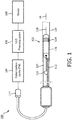
- Fig. 1 is a diagrammatic schematic view of an intravascular ultrasound (IVUS) imaging system 100, according to aspects of the present disclosure.
- the IVUS imaging system 100 may include a solid-state IVUS device 102 such as a catheter, guide wire, or guide catheter, a patient interface module (PIM) 104, an IVUS processing system or console 106, and a monitor 108.
- PIM patient interface module
- the IVUS device 102 emits ultrasonic energy from a transducer array 124 included in imaging assembly 110 mounted near a distal end of the catheter device.
- the ultrasonic energy is reflected by tissue structures in the medium, such as a vessel 120, surrounding the imaging assembly 110, and the ultrasound echo signals are received by the transducer array 124.
- the PIM 104 transfers the received echo signals to the processing system 106 where the ultrasound image (including the flow information) is reconstructed and displayed on the monitor 108.
- the processing system 106 can include a processor and a memory.
- the processing system 106 can be operable to facilitate the features of the IVUS imaging system 100 described herein.
- the processor can execute computer readable instructions stored on the non-transitory tangible computer readable medium.
- the PIM 104 facilitates communication of signals between the processing system 106 and the imaging assembly 110 included in the IVUS device 102.
- This communication includes the steps of: (1) providing commands to integrated circuit controller chip(s) 206A, 206B, illustrated in Fig. 2 , included in the imaging assembly 110 to select the particular transducer array element(s) to be used for transmit and receive, (2) providing the transmit trigger signals to the integrated circuit controller chip(s) 206A, 206B included in the imaging assembly 110 to activate the transmitter circuitry to generate an electrical pulse to excite the selected transducer array element(s), and/or (3) accepting amplified echo signals received from the selected transducer array element(s) via amplifiers included on the integrated circuit controller chip(s) of the imaging assembly 110.
- the PIM 104 performs preliminary processing of the echo data prior to relaying the data to the processing system 106. In examples of such embodiments, the PIM 104 performs amplification, filtering, and/or aggregating of the data. In an embodiment, the PIM 104 also supplies high- and low-voltage DC power to support operation of the IVUS device 102 including circuitry within the imaging assembly 110.
- the processing system 106 receives the echo data from the imaging assembly 110 by way of the PIM 104 and processes the data to reconstruct an image of the tissue structures in the medium surrounding the imaging assembly 110.
- the processing system 106 outputs image data such that an image of the vessel 120, such as a cross-sectional image of the vessel 120, is displayed on the monitor 108.
- Vessel 120 may represent fluid filled or surrounded structures, both natural and man-made.
- the vessel 120 may be within a body of a patient.
- the vessel 120 may be a blood vessel, as an artery or a vein of a patient's vascular system, including cardiac vasculature, peripheral vasculature, neural vasculature, renal vasculature, and/or or any other suitable lumen inside the body.
- the IVUS device 102 may be used to examine any number of anatomical locations and tissue types, including without limitation, organs including the liver, heart, kidneys, gall bladder, pancreas, lungs; ducts; intestines; nervous system structures including the brain, dural sac, spinal cord and peripheral nerves; the urinary tract; as well as valves within the blood, chambers or other parts of the heart, and/or other systems of the body.
- the IVUS device 102 may be used to examine man-made structures such as, but without limitation, heart valves, stents, shunts, filters and other devices.
- the IVUS device includes some features similar to traditional solid-state IVUS catheters, such as the EagleEye® catheter available from Volcano Corporation and those disclosed in U.S. Patent No. 7,846,101 .
- the IVUS device 102 includes the imaging assembly 110 near a distal end of the IVUS device 102 and an electrical cable 112 extending along the longitudinal body of the IVUS device 102.
- the electrical cable 112 can include a plurality of conductors, including one, two, three, four, five, six, seven, or more conductors 218 ( Fig. 2 ). It is understood that any suitable gauge wire can be used for the conductors 218.
- the electrical cable 112 can include a four-conductor transmission line arrangement with, e.g., 41 AWG gauge wires. In an embodiment, the electrical cable 112 can include a seven-conductor transmission line arrangement utilizing, e.g., 44 AWG gauge wires. In some embodiments, 43 AWG gauge wires can be used.
- the electrical cable 112 terminates in a PIM connector 114 at a proximal end of the IVUS device 102.
- the PIM connector 114 electrically couples the electrical cable 112 to the PIM 104 and physically couples the IVUS device 102 to the PIM 104.
- the IVUS device 102 further includes a guide wire exit port 116. Accordingly, in some instances the IVUS device is a rapid-exchange catheter.
- the guide wire exit port 116 allows a guide wire 118 to be inserted towards the distal end in order to direct the device 102 through the vessel 120.
- the IVUS device 102 includes a flexible elongate member 115 having a proximal portion and a distal portion.
- the imaging assembly 110 is positioned at a distal portion of the flexible elongate member 115.
- the flexible elongate member 115 includes a longitudinal axis LA.
- the longitudinal axis LA may be associated with the IVUS device 102 and/or the imaging assembly 110.
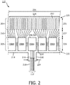
- Fig. 2 is a top view of a portion of an ultrasound imaging assembly 110 according to an embodiment of the present disclosure.
- the imaging assembly 110 includes a transducer array 124 formed in a transducer region 204 and transducer control logic dies 206 (including dies 206A and 206B) formed in a control region 208, with a transition region 210 disposed therebetween.
- the transducer control logic dies 206 and the transducers 212 are mounted on a flexible substrate 214 that is shown in a flat configuration in Fig. 2 .
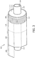
- Fig. 3 illustrates a rolled configuration of the flexible substrate 214.
- the transducer array is a non-limiting example of a medical sensor element and/or a medical sensor element array.
- the transducer control logic dies 206 is a non-limiting example of a control circuit.
- the transducer region 204 is disposed adjacent a distal portion 221 of the flexible substrate 214.
- the control region 208 is disposed adjacent the proximal portion 222 of the flexible substrate 214.
- the transition region 210 is disposed between the control region 208 and the transducer region 204. Dimensions of the transducer region 204, the control region 208, and the transition region 210 (e.g., lengths 225, 227, 229) can vary in different embodiments.
- the lengths 225, 227, 229 can be substantially similar or a length 227 of the transition region 210 can be greater than lengths 225, 229 of the transducer region and controller region, respectively.
- the imaging assembly 110 is described as including a flexible substrate, it is understood that the transducers and/or controllers may be arranged to form the imaging assembly 110 in other configurations, including those omitting a flexible substrate.
- the transducer array 124 may include any number and type of ultrasound transducers 212, although for clarity only a limited number of ultrasound transducers are illustrated in Fig. 2 .
- the transducer array 124 includes 64 individual ultrasound transducers 212.
- the transducer array 124 includes 32 ultrasound transducers 212.
- Other numbers are both contemplated and provided for.
- the ultrasound transducers 212 are piezoelectric micromachined ultrasound transducers (PMUTs) fabricated on a microelectromechanical system (MEMS) substrate using a polymer piezoelectric material, for example as disclosed in U.S. Patent 6,641,540 .
- the transducer array includes piezoelectric zirconate transducers (PZT) transducers such as bulk PZT transducers, capacitive micromachined ultrasound transducers (cMUTs), single crystal piezoelectric materials, other suitable ultrasound transmitters and receivers, and/or combinations thereof.
- PZT piezoelectric zirconate transducers
- cMUTs capacitive micromachined ultrasound transducers
- single crystal piezoelectric materials other suitable ultrasound transmitters and receivers, and/or combinations thereof.
- the imaging assembly 110 may include various transducer control logic, which in the illustrated embodiment is divided into discrete control logic dies 206.
- the control logic of the imaging assembly 110 performs: decoding control signals sent by the PIM 104 across the electrical cable 112, driving one or more transducers 212 to emit an ultrasonic signal, selecting one or more transducers 212 to receive a reflected echo of the ultrasonic signal, amplifying a signal representing the received echo, and/or transmitting the signal to the PIM across the electrical cable 112.
- a imaging assembly 110 having 64 ultrasound transducers 212 divides the control logic across nine control logic dies 206, of which five are shown in Fig. 2 .
- control logic dies 206 are characterized by the number of transducers they are capable of driving, and exemplary control logic dies 206 drive 4, 8, and/or 16 transducers.
- the control logic dies are not necessarily homogenous.
- a single controller is designated a master control logic die 206A and contains the communication interface for the electrical cable 112.
- the master control circuit may include control logic that decodes control signals received over the electrical cable 112, transmits control responses over the electrical cable 112, amplifies echo signals, and/or transmits the echo signals over the electrical cable 112.
- the remaining controllers are slave controllers 206B.
- the slave controllers 206B may include control logic that drives a transducer 212 to emit an ultrasonic signal and selects a transducer 212 to receive an echo.
- the master controller 206A does not directly control any transducers 212.
- the master controller 206A drives the same number of transducers 212 as the slave controllers 206B or drives a reduced set of transducers 212 as compared to the slave controllers 206B.
- a single master controller 206A and eight slave controllers 206B are provided with eight transducers assigned to each slave controller 206B.
- the flexible substrate 214 on which the transducer control logic dies 206 and the transducers 212 are mounted, provides structural support and interconnects for electrical coupling.
- the flexible substrate 214 may be constructed to include a film layer of a flexible polyimide material such as KAPTONTM (trademark of DuPont).
- KAPTONTM trademark of DuPont
- Other suitable materials include polyester films, polyimide films, polyethylene napthalate films, or polyetherimide films, other flexible printed semiconductor substrates as well as products such as Upilex® (registered trademark of Ube Industries) and TEFLON® (registered trademark of E.I. du Pont).
- Upilex® registered trademark of Ube Industries
- TEFLON® registered trademark of E.I. du Pont
- the flexible substrate 214 is configured to be wrapped around a tubular member 230 ( Fig. 3 ) to form a cylindrical toroid in some instances. Therefore, the thickness of the film layer of the flexible substrate 214 is generally related to the degree of curvature in the final assembled imaging assembly 110. In some embodiments, the film layer is between 5 ⁇ m and 100 ⁇ m, with some particular embodiments being between 12.7 ⁇ m and 25.1 ⁇ m.
- the flexible substrate 214 further includes conductive traces 216 formed on the film layer that carry signals between the control logic dies 206 and the transducers 212.
- the conductive traces 216 providing communication between the control logic dies 206 and the transducers 212 extend along the flexible substrate 214 within the transition region 210.
- the conductive traces 216 can also facilitate electrical communication between the master controller 206A and the slave controllers 206B.
- the conductive traces 216 can also provide a set of conductive pads that contact the conductors 218 of cable 112 when the conductors 218 of the electrical cable 112 are mechanically and electrically coupled to the flexible substrate 214.
- Suitable materials for the conductive traces 216 include copper, gold, aluminum, silver, tantalum, nickel, and tin, and may be deposited on the flexible substrate 214 by processes such as sputtering, plating, and etching.
- the flexible substrate 214 includes a chromium adhesion layer.
- the width and thickness of the conductive traces 216 are selected to provide proper conductivity and resilience when the flexible substrate 214 is rolled. In that regard, an exemplary range for the thickness of a conductive trace 216 and/or conductive pad is between 10-50 ⁇ m. For example, in an embodiment, 20 ⁇ m conductive traces 216 are separated by 20 ⁇ m of space.
- the width of a conductive trace 216 on the flexible substrate 214 may be further determined by the width of the conductor 218 to be coupled to the trace/pad.
- the flexible substrate 214 can include a connection interface 220 in some embodiments.
- the connection interface 220 can be a location of the flexible substrate 214 where the conductors 218 of the electrical cable 112 are coupled to the flexible substrate 214.
- the bare conductors of the electrical cable 112 are electrically coupled to the flexible substrate 214 at the connection interface 220.
- the connection interface 220 can be a tab extending from the main body of flexible substrate 214.
- the main body of the flexible substrate 214 can refer collectively to the transducer region 204, controller region 208, and the transition region 210.
- the connection interface 220 extends from the proximal portion 222 of the flexible substrate 214.
- connection interface 220 is positioned at other parts of the flexible substrate 214, such as the distal portion 221, or the flexible substrate 214 omits the connection interface 220.
- the substrate forming the connection interface 220 is made of the same material(s) and/or is similarly flexible as the flexible substrate 214. In other embodiments, the connection interface 220 is made of different materials and/or is comparatively more rigid than the flexible substrate 214.
- connection interface 220 can be made of a plastic, thermoplastic, polymer, hard polymer, etc., including polyoxymethylene (e.g., DELRIN®), polyether ether ketone (PEEK), nylon, and/or other suitable materials.
- polyoxymethylene e.g., DELRIN®
- PEEK polyether ether ketone
- nylon e.g., nylon
- the tubular member 230, the flexible substrate 214, the connection interface 220 and/or the conductor(s) 218 can be variously configured to facilitate efficient manufacturing and operation of the imaging assembly 110.
- the imaging assembly 110 is transitioned from a flat configuration ( Fig. 2 ) to a rolled or more cylindrical configuration ( Figs. 3 and 4 ).
- techniques are utilized as disclosed in one or more of U.S. Patent No. 6,776,763 , titled “ULTRASONIC TRANSDUCER ARRAY AND METHOD OF MANUFACTURING THE SAME" and U.S. Patent No. 7,226,417 , titled “HIGH RESOLUTION INTRAVASCULAR ULTRASOUND TRANSDUCER ASSEMBLY HAVING A FLEXIBLE SUBSTRATE".
- the flexible substrate 214 is positioned around the tubular member 230 in the rolled configuration.
- Fig. 3 is a diagrammatic side view with the flexible substrate 214 in the rolled configuration around the tubular member 230, according to aspects of the present disclosure.
- the tubular member 230 can be referenced as a unibody in some instances.
- the tubular member 230 can be composed of a metallic material, such as stainless steel, or non-metallic material, such as a plastic or polymer as described in U.S. Provisional Application No. 61/985,220 , "Pre-Doped Solid Substrate for Intravascular Devices," filed April 28, 2014 (published as US 2015/0305710 A1 ).
- the tubular member 230 can have a distal section 232, a proximal section 234, and a lumen 236 extending longitudinally therethrough.
- the lumen 236 can be in communication with the exit port 116 and is sized and shaped to receive the guide wire 118 ( Fig. 1 ).
- the tubular member 230 can be manufactured accordingly to any suitable process.
- the tubular member 230 can be machined, such as by removing material from a blank to shape the tubular member 230, or molded, such as by an injection molding process.
- the tubular member 230 may be integrally formed as a unitary structure, while in other embodiments the tubular member 230 may be formed of different components.
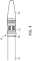
- Fig. 4 illustrates an IVUS device 102 according to an exemplary embodiment of the present disclosure.
- the IVUS device 102 includes an imaging assembly 110, a tip 305, a support member 300, and a flexible elongate member 115.
- the flexible elongate member 115 can include a flexible outer catheter shaft and/or a flexible inner member.
- the imaging assembly 110 is connected to the flexible elongate member 115 through the support member 300.
- a distal portion of flexible elongate member 115 is pre-flared to receive the support member 300 therewithin, resulting in a relatively large diameter near or at the distal portion of flexible elongate member 115 compared to more proximal portions.
- an outer diameter of flexible elongate member and an outer diameter of imaging assembly 110 are of substantially the same diameter when support member 300 is received within the distal portion of flexible elongate member 115.
- the support member 300 is made of a metal or metal alloy.
- the support member 300 is made of plastic or polymer, such as Pebax®, polyethylene (PE), polyethylene terephthalate (PET), polyimide (PI), polyester or a blend thereof.
- the support member 300 is a concentric composite of two layers of materials to achieve flexibility.
- the support member 300 can be structured to allow more adhesion surface for adhesive to provide durability, flexibility, and a complete electrical seal at the junction while maintaining a low catheter profile.
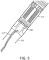
- Fig. 5 is an image of the junction between to a flexible elongate member 115 and an imaging assembly 110. As can be seen through the translucent flexible elongate member 115, a connection interface 220 from the imaging assembly 110 is bonded to an electrical cable 112. The electrical cable 112 extends along a length of the flexible elongate member 115. Connection interface 220 and electrical cable 112 are also shown in Fig. 2 .
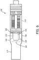
- FIG. 6 is a diagrammatic side view of a junction between the flexible elongate member 115 and the imaging assembly 110
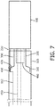
- Fig. 7 is a diagrammatic side see-through view of the junction between the flexible elongate member 115 and the imaging assembly 110
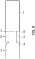
- Fig. 8 is a diagrammatic side view of the junction between the flexible elongate member 115 and the imaging assembly 110.
- Figs. 6 , 7 , and 8 illustrate various features of the support member 300 and how the support member 300 interfaces with different components of the IVUS device 102 according to aspects of the present disclosure.
- the support member 300 includes a proximal section 310 and a distal section 320.
- the distal section 320 has a diameter that is smaller than that of the proximal section 310.
- both the proximal section 310 and distal section 320 are cylindrical with uniform diameters throughout their respective lengths. This design includes a stepped change of diameters when the proximal section 310 transitions into the distal section 320.
- the distal section 320 is a conical taper and transitions from a diameter at the transition point near the proximal section 310 to a smaller diameter at a distal end of the distal section 320.
- the side profile of the distal section 320 has different features to enhance adhesive adhesion or mechanical strength of the junction between the flexible elongate member 115 and the imaging assembly 110.
- the side profile of the distal section 320 can have ridges (not shown).
- connection interface 220 extends from the imaging assembly 110 and over the support member 300. As shown in Fig. 6 , in some embodiments, the connection interface 220 extends over the distal section 320 and a portion of the proximal section 310. In some embodiments, the connection interface 220 only extends over the distal section 320 or a portion of the distal section 320. In some embodiments, the connection interface 220 is mounted on the support member 300. For example, the connection interface 220 can be mounted on an outer surface of the proximal section 310.
- annular lumen 340 is ring-shaped or donut-shaped when the distal section 320 is cylindrical with a uniform diameter along its length.
- the resulting annular lumen 340 would have a corresponding or reciprocal shape.
- the distal end of the flexible elongate member 115 When the distal end of the distal section 320 engages or is coupled to the proximal end of the imaging assembly 110, the distal end of the flexible elongate member 115 is separated from the proximal end of the imaging assembly 110 by a gap 350.
- the gap 350 is in fluid communication with the annular lumen 340 such that when adhesive is supplied through the gap 350, the adhesive fills the annular lumen 340 and eventually the gap 350 as well.
- the gap is about 0.5mm.
- the support member 300 includes a lumen extending longitudinally through the proximal section 310 and the distal section 320.
- the imaging assembly 110 includes a tubular member 460 extending proximally from the proximal end of the imaging assembly 110.
- the support member 300 is configured to receive the tubular member 460.
- the inner surface of the lumen is treated by plasma or with other surface roughening processes.
- the surface roughening processes include application of a surface treatment agent, such as a primer.
- connection interface 220 extends towards the flexible elongate member 115 and is bonded to the electrical cable 112 at the connection point 420.
- the electrical cable 112 is threaded through an opening 430 on or near the proximal section 310 of the support member 300. The opening 430 is adjacent to the connection point 420.
- the electrical cable 112 extends over the proximal section 310 between the proximal section 310 and the inner surface of the flexible elongate member 115 and the support member 300 does not have the opening 430.
- an inner member 450 extends through the flexible elongate member 115, the lumen within the support member 300, and the tubular member 460. The inner member 450 is configured to receive a guidewire such that the IVUS device 102 can travel along the guidewire to the target location in a patient's vessel.
- Fig. 8 illustrates how the adhesive 500 fills the annular lumen 340 and the gap 350.
- the adhesive 500 is supplied through the gap 350 and fills both the annular lumen 340 and the gap 350.
- the adhesive 500 in the annular lumen 340 and the gap 350 needs to be cured.
- the adhesive 500 is water-curable and is cured by being exposed to moisture.
- the adhesive 500 is thermal-curable and is cured by being exposed to a heat source at a temperature substantially higher than room temperature.
- the adhesive 500 is UV-curable and is cured by being exposed to ultraviolet (UV) light from a UV source. As shown in Fig.
- UV ultraviolet
- the flexible elongate member 115 is translucent and when the imaging device is exposed to UV, UV energy can effectively go through the flexible elongate member 115 and cure the adhesive 500 within the annular lumen 340.
- the adhesive in the gap 350 has an outer surface 510.
- the outer surface 510 is substantially level and coplanar with the outer surface of the flexible elongate member 115 and the outer surface of the imaging assembly 110.
- the adhesive 500 is flexible when it is cured.
- the adhesive 500 can be acrylic, epoxy-based, or cyanoacrylate.
- FIG. 9A is a diagrammatic perspective view of the support member 300
- Fig. 9B is a diagrammatic side view of the support member 300
- Fig. 9C is diagrammatic side view of the support member 300.
- Figs. 9A-9C illustrate various features of the support member 300 according to aspects of the present disclosure.
- the support member 300 includes the proximal section 310 that transitions to the distal section 320 via a taper section 315.
- the support member 300 includes an opening 430.
- an electrical cable such as the electrical cable 112 can be threaded through the opening 430 to be bonded with the connection interface 220 (not shown in Fig. 9A ).
- the opening 430 keeps secure the connection/bonding between the electrical cable 112 and the connection interface 220.
- any electrical cable threaded through the opening 430 undergoes minimum or no bending and is less prone to breakage or electrical shorts.
- the support member 300 has a length L; the distal section 320 has an outer diameter D1 and an inner diameter D2; the proximal section 310 has a length Lp, an outer diameter D3 and an inner diameter D4; and the opening 430 has an diameter D5.
- L is between approximately 0.060 and 0.157 inches.
- Lp is between approximately 0.05 and 0.1 inches.
- D1 is between approximately 0.030 and 0.035 inches and D2 is between approximately 0.025 and 0.030 inches.
- D3 is between approximately 0.035 and 0.040 inches and D4 is between 0.030 and 0.035 inches.
- D5 is between approximately 0.01 inches and approximately 0.02 inches, including values such as approximately 0.015 inches.
- D1 is about 0.033 inches
- D2 is about 0.027 inches
- D3 is about 0.037 to 0.038 inches
- D is about 0.032 inches.
- Fig. 9C is a diagrammatic side view of the support member 300.
- the taper section 315 has a conical surface that extends from the proximal section 310 to the distal section 320.
- the conical surface has an inclined angle A.
- A is between approximately 4 degrees and approximately 5.6 degrees, including values such as 4.8 degrees.
- due to this inclined angle A the opening of the opening 430 is tilted towards the distal section 320.
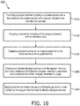
- Fig. 10 shows a flow diagram of a method 600 of forming an intraluminal imaging device according to aspects of the present disclosure.
- the method 600 includes steps 610, 620, 630, 640, and 650.
- a support member 300 is provided.
- the support member 300 includes a proximal section 310 with a first diameter and a distal section 320 with a second diameter less than the first diameter.
- a connection interface 220 of the imaging assembly 110 is coupled to an electrical cable 112.
- the electrical cable 112 goes through an opening 430 before being coupled to the connection interface 220.
- step 620 includes threading the electrical cable 112 through the opening 430.
- a proximal portion of an imaging assembly 110 is coupled to a distal section 320 of the support member 300.
- the flexible elongate member 115 is positioned over the support member 300 such that a distal end of the flexible elongate member 115 is separated from a proximal end of the imaging assembly 110 by a gap 350.
- an adhesive is supplied through the gap 350 and is allowed to fill the gap 350 and the annular lumen 340 defined by the support member 300 and the flexible elongate member 115.
- the adhesive needs to be cured and step 650 includes curing the adhesive by heat, moisture or UV.
Landscapes
- Health & Medical Sciences (AREA)
- Life Sciences & Earth Sciences (AREA)
- Engineering & Computer Science (AREA)
- General Health & Medical Sciences (AREA)
- Biophysics (AREA)
- Veterinary Medicine (AREA)
- Biomedical Technology (AREA)
- Heart & Thoracic Surgery (AREA)
- Public Health (AREA)
- Animal Behavior & Ethology (AREA)
- Pathology (AREA)
- Physics & Mathematics (AREA)
- Nuclear Medicine, Radiotherapy & Molecular Imaging (AREA)
- Radiology & Medical Imaging (AREA)
- Medical Informatics (AREA)
- Molecular Biology (AREA)
- Surgery (AREA)
- Hematology (AREA)
- Anesthesiology (AREA)
- Pulmonology (AREA)
- Vascular Medicine (AREA)
- Ultra Sonic Daignosis Equipment (AREA)
- Computer Vision & Pattern Recognition (AREA)
Applications Claiming Priority (2)
| Application Number | Priority Date | Filing Date | Title |
|---|---|---|---|
| US201762504600P | 2017-05-11 | 2017-05-11 | |
| PCT/EP2018/061239 WO2018206369A1 (en) | 2017-05-11 | 2018-05-03 | Support member for intraluminal imaging devices and associated devices, systems, and methods |
Publications (2)
| Publication Number | Publication Date |
|---|---|
| EP3621526A1 EP3621526A1 (en) | 2020-03-18 |
| EP3621526B1 true EP3621526B1 (en) | 2021-07-07 |
Family
ID=62186397
Family Applications (1)
| Application Number | Title | Priority Date | Filing Date |
|---|---|---|---|
| EP18725120.2A Active EP3621526B1 (en) | 2017-05-11 | 2018-05-03 | Intraluminal imaging device |
Country Status (5)
| Country | Link |
|---|---|
| US (1) | US11980723B2 (cg-RX-API-DMAC7.html) |
| EP (1) | EP3621526B1 (cg-RX-API-DMAC7.html) |
| JP (1) | JP6991245B2 (cg-RX-API-DMAC7.html) |
| CN (1) | CN110740690B (cg-RX-API-DMAC7.html) |
| WO (1) | WO2018206369A1 (cg-RX-API-DMAC7.html) |
Families Citing this family (3)
| Publication number | Priority date | Publication date | Assignee | Title |
|---|---|---|---|---|
| US12186131B2 (en) * | 2019-10-08 | 2025-01-07 | Koninklijke Philips N.V. | Intraluminal ultrasound assembly having a multiple material support member, and associated devices, systems, and methods |
| JP7571474B2 (ja) * | 2020-11-02 | 2024-10-23 | 住友ベークライト株式会社 | カテーテル |
| WO2022152724A1 (en) * | 2021-01-15 | 2022-07-21 | Koninklijke Philips N.V. | Flexible adhesive-filled distal region for intraluminal imaging device |
Family Cites Families (11)
| Publication number | Priority date | Publication date | Assignee | Title |
|---|---|---|---|---|
| US5108369A (en) | 1990-03-15 | 1992-04-28 | Diagnostic Devices Group, Limited | Dual-diameter multifunction catheter |
| EP0671221B1 (en) * | 1994-03-11 | 2000-04-26 | Intravascular Research Limited | Ultrasonic transducer array and method of manufacturing the same |
| JP3248344B2 (ja) * | 1994-04-07 | 2002-01-21 | 富士写真光機株式会社 | 体内挿入型超音波診断装置 |
| US7226417B1 (en) | 1995-12-26 | 2007-06-05 | Volcano Corporation | High resolution intravascular ultrasound transducer assembly having a flexible substrate |
| JP3525700B2 (ja) * | 1997-09-24 | 2004-05-10 | 富士写真光機株式会社 | 超音波プローブ |
| US6261246B1 (en) * | 1997-09-29 | 2001-07-17 | Scimed Life Systems, Inc. | Intravascular imaging guidewire |
| CA2429940C (en) | 2000-12-01 | 2008-07-08 | The Cleveland Clinic Foundation | Miniature ultrasound transducer |
| JP4069003B2 (ja) * | 2003-04-03 | 2008-03-26 | オリンパス株式会社 | 超音波プローブ |
| CN112603273B (zh) * | 2014-04-23 | 2024-12-10 | 皇家飞利浦有限公司 | 具有用于成像和压力感测的集成控制器的导管 |
| US11413017B2 (en) * | 2014-04-28 | 2022-08-16 | Philips Image Guided Therapy Corporation | Pre-doped solid substrate for intravascular devices |
| CN107072559A (zh) * | 2014-08-28 | 2017-08-18 | 皇家飞利浦有限公司 | 具有填充有粘合剂的柔性元件的血管内设备、系统和方法 |
-
2018
- 2018-05-03 US US16/611,309 patent/US11980723B2/en active Active
- 2018-05-03 JP JP2019561929A patent/JP6991245B2/ja active Active
- 2018-05-03 CN CN201880038716.7A patent/CN110740690B/zh active Active
- 2018-05-03 EP EP18725120.2A patent/EP3621526B1/en active Active
- 2018-05-03 WO PCT/EP2018/061239 patent/WO2018206369A1/en not_active Ceased
Non-Patent Citations (1)
| Title |
|---|
| None * |
Also Published As
| Publication number | Publication date |
|---|---|
| JP6991245B2 (ja) | 2022-01-12 |
| EP3621526A1 (en) | 2020-03-18 |
| CN110740690B (zh) | 2023-03-21 |
| US20200163651A1 (en) | 2020-05-28 |
| WO2018206369A1 (en) | 2018-11-15 |
| JP2020519368A (ja) | 2020-07-02 |
| US11980723B2 (en) | 2024-05-14 |
| CN110740690A (zh) | 2020-01-31 |
Similar Documents
| Publication | Publication Date | Title |
|---|---|---|
| US11944489B2 (en) | Imaging assembly for intravascular imaging device and associated devices, systems, and methods | |
| US11857362B2 (en) | Imaging assembly for intravascular imaging device and associated devices, systems, and methods | |
| US20230240647A1 (en) | Intraluminal imaging device with wire interconnection for imaging assembly | |
| US12343202B2 (en) | Standalone flex circuit for intravascular imaging device and associated devices, systems, and methods | |
| JP7609071B2 (ja) | 管腔内超音波画像のための歪み軽減、並びに関連する装置、システム、及び方法 | |
| EP3518772B1 (en) | Flexible imaging assembly for intraluminal imaging and associated devices and systems | |
| EP3435880B1 (en) | Flexible support member for intravascular imaging device and associated devices, systems, and methods | |
| US20190247017A1 (en) | Inner member for intravascular imaging device and associated devices, systems, and methods | |
| US11980723B2 (en) | Support member for intraluminal imaging devices and associated devices, systems, and methods | |
| EP3568081B1 (en) | Support members for connection of components in intraluminal devices, systems, and methods |
Legal Events
| Date | Code | Title | Description |
|---|---|---|---|
| STAA | Information on the status of an ep patent application or granted ep patent |
Free format text: STATUS: UNKNOWN |
|
| STAA | Information on the status of an ep patent application or granted ep patent |
Free format text: STATUS: THE INTERNATIONAL PUBLICATION HAS BEEN MADE |
|
| PUAI | Public reference made under article 153(3) epc to a published international application that has entered the european phase |
Free format text: ORIGINAL CODE: 0009012 |
|
| STAA | Information on the status of an ep patent application or granted ep patent |
Free format text: STATUS: REQUEST FOR EXAMINATION WAS MADE |
|
| 17P | Request for examination filed |
Effective date: 20191211 |
|
| AK | Designated contracting states |
Kind code of ref document: A1 Designated state(s): AL AT BE BG CH CY CZ DE DK EE ES FI FR GB GR HR HU IE IS IT LI LT LU LV MC MK MT NL NO PL PT RO RS SE SI SK SM TR |
|
| AX | Request for extension of the european patent |
Extension state: BA ME |
|
| DAV | Request for validation of the european patent (deleted) | ||
| DAX | Request for extension of the european patent (deleted) | ||
| GRAP | Despatch of communication of intention to grant a patent |
Free format text: ORIGINAL CODE: EPIDOSNIGR1 |
|
| STAA | Information on the status of an ep patent application or granted ep patent |
Free format text: STATUS: GRANT OF PATENT IS INTENDED |
|
| INTG | Intention to grant announced |
Effective date: 20201214 |
|
| GRAS | Grant fee paid |
Free format text: ORIGINAL CODE: EPIDOSNIGR3 |
|
| GRAA | (expected) grant |
Free format text: ORIGINAL CODE: 0009210 |
|
| STAA | Information on the status of an ep patent application or granted ep patent |
Free format text: STATUS: THE PATENT HAS BEEN GRANTED |
|
| AK | Designated contracting states |
Kind code of ref document: B1 Designated state(s): AL AT BE BG CH CY CZ DE DK EE ES FI FR GB GR HR HU IE IS IT LI LT LU LV MC MK MT NL NO PL PT RO RS SE SI SK SM TR |
|
| REG | Reference to a national code |
Ref country code: GB Ref legal event code: FG4D |
|
| REG | Reference to a national code |
Ref country code: AT Ref legal event code: REF Ref document number: 1407786 Country of ref document: AT Kind code of ref document: T Effective date: 20210715 |
|
| REG | Reference to a national code |
Ref country code: DE Ref legal event code: R096 Ref document number: 602018019725 Country of ref document: DE |
|
| REG | Reference to a national code |
Ref country code: IE Ref legal event code: FG4D |
|
| REG | Reference to a national code |
Ref country code: LT Ref legal event code: MG9D |
|
| REG | Reference to a national code |
Ref country code: NL Ref legal event code: MP Effective date: 20210707 |
|
| REG | Reference to a national code |
Ref country code: AT Ref legal event code: MK05 Ref document number: 1407786 Country of ref document: AT Kind code of ref document: T Effective date: 20210707 |
|
| PG25 | Lapsed in a contracting state [announced via postgrant information from national office to epo] |
Ref country code: RS Free format text: LAPSE BECAUSE OF FAILURE TO SUBMIT A TRANSLATION OF THE DESCRIPTION OR TO PAY THE FEE WITHIN THE PRESCRIBED TIME-LIMIT Effective date: 20210707 Ref country code: SE Free format text: LAPSE BECAUSE OF FAILURE TO SUBMIT A TRANSLATION OF THE DESCRIPTION OR TO PAY THE FEE WITHIN THE PRESCRIBED TIME-LIMIT Effective date: 20210707 Ref country code: HR Free format text: LAPSE BECAUSE OF FAILURE TO SUBMIT A TRANSLATION OF THE DESCRIPTION OR TO PAY THE FEE WITHIN THE PRESCRIBED TIME-LIMIT Effective date: 20210707 Ref country code: ES Free format text: LAPSE BECAUSE OF FAILURE TO SUBMIT A TRANSLATION OF THE DESCRIPTION OR TO PAY THE FEE WITHIN THE PRESCRIBED TIME-LIMIT Effective date: 20210707 Ref country code: FI Free format text: LAPSE BECAUSE OF FAILURE TO SUBMIT A TRANSLATION OF THE DESCRIPTION OR TO PAY THE FEE WITHIN THE PRESCRIBED TIME-LIMIT Effective date: 20210707 Ref country code: PT Free format text: LAPSE BECAUSE OF FAILURE TO SUBMIT A TRANSLATION OF THE DESCRIPTION OR TO PAY THE FEE WITHIN THE PRESCRIBED TIME-LIMIT Effective date: 20211108 Ref country code: NO Free format text: LAPSE BECAUSE OF FAILURE TO SUBMIT A TRANSLATION OF THE DESCRIPTION OR TO PAY THE FEE WITHIN THE PRESCRIBED TIME-LIMIT Effective date: 20211007 Ref country code: NL Free format text: LAPSE BECAUSE OF FAILURE TO SUBMIT A TRANSLATION OF THE DESCRIPTION OR TO PAY THE FEE WITHIN THE PRESCRIBED TIME-LIMIT Effective date: 20210707 Ref country code: AT Free format text: LAPSE BECAUSE OF FAILURE TO SUBMIT A TRANSLATION OF THE DESCRIPTION OR TO PAY THE FEE WITHIN THE PRESCRIBED TIME-LIMIT Effective date: 20210707 Ref country code: BG Free format text: LAPSE BECAUSE OF FAILURE TO SUBMIT A TRANSLATION OF THE DESCRIPTION OR TO PAY THE FEE WITHIN THE PRESCRIBED TIME-LIMIT Effective date: 20211007 Ref country code: LT Free format text: LAPSE BECAUSE OF FAILURE TO SUBMIT A TRANSLATION OF THE DESCRIPTION OR TO PAY THE FEE WITHIN THE PRESCRIBED TIME-LIMIT Effective date: 20210707 |
|
| PG25 | Lapsed in a contracting state [announced via postgrant information from national office to epo] |
Ref country code: PL Free format text: LAPSE BECAUSE OF FAILURE TO SUBMIT A TRANSLATION OF THE DESCRIPTION OR TO PAY THE FEE WITHIN THE PRESCRIBED TIME-LIMIT Effective date: 20210707 Ref country code: LV Free format text: LAPSE BECAUSE OF FAILURE TO SUBMIT A TRANSLATION OF THE DESCRIPTION OR TO PAY THE FEE WITHIN THE PRESCRIBED TIME-LIMIT Effective date: 20210707 Ref country code: GR Free format text: LAPSE BECAUSE OF FAILURE TO SUBMIT A TRANSLATION OF THE DESCRIPTION OR TO PAY THE FEE WITHIN THE PRESCRIBED TIME-LIMIT Effective date: 20211008 |
|
| REG | Reference to a national code |
Ref country code: DE Ref legal event code: R097 Ref document number: 602018019725 Country of ref document: DE |
|
| PG25 | Lapsed in a contracting state [announced via postgrant information from national office to epo] |
Ref country code: DK Free format text: LAPSE BECAUSE OF FAILURE TO SUBMIT A TRANSLATION OF THE DESCRIPTION OR TO PAY THE FEE WITHIN THE PRESCRIBED TIME-LIMIT Effective date: 20210707 |
|
| PLBE | No opposition filed within time limit |
Free format text: ORIGINAL CODE: 0009261 |
|
| STAA | Information on the status of an ep patent application or granted ep patent |
Free format text: STATUS: NO OPPOSITION FILED WITHIN TIME LIMIT |
|
| PG25 | Lapsed in a contracting state [announced via postgrant information from national office to epo] |
Ref country code: SM Free format text: LAPSE BECAUSE OF FAILURE TO SUBMIT A TRANSLATION OF THE DESCRIPTION OR TO PAY THE FEE WITHIN THE PRESCRIBED TIME-LIMIT Effective date: 20210707 Ref country code: SK Free format text: LAPSE BECAUSE OF FAILURE TO SUBMIT A TRANSLATION OF THE DESCRIPTION OR TO PAY THE FEE WITHIN THE PRESCRIBED TIME-LIMIT Effective date: 20210707 Ref country code: RO Free format text: LAPSE BECAUSE OF FAILURE TO SUBMIT A TRANSLATION OF THE DESCRIPTION OR TO PAY THE FEE WITHIN THE PRESCRIBED TIME-LIMIT Effective date: 20210707 Ref country code: EE Free format text: LAPSE BECAUSE OF FAILURE TO SUBMIT A TRANSLATION OF THE DESCRIPTION OR TO PAY THE FEE WITHIN THE PRESCRIBED TIME-LIMIT Effective date: 20210707 Ref country code: CZ Free format text: LAPSE BECAUSE OF FAILURE TO SUBMIT A TRANSLATION OF THE DESCRIPTION OR TO PAY THE FEE WITHIN THE PRESCRIBED TIME-LIMIT Effective date: 20210707 Ref country code: AL Free format text: LAPSE BECAUSE OF FAILURE TO SUBMIT A TRANSLATION OF THE DESCRIPTION OR TO PAY THE FEE WITHIN THE PRESCRIBED TIME-LIMIT Effective date: 20210707 |
|
| 26N | No opposition filed |
Effective date: 20220408 |
|
| PG25 | Lapsed in a contracting state [announced via postgrant information from national office to epo] |
Ref country code: IT Free format text: LAPSE BECAUSE OF FAILURE TO SUBMIT A TRANSLATION OF THE DESCRIPTION OR TO PAY THE FEE WITHIN THE PRESCRIBED TIME-LIMIT Effective date: 20210707 |
|
| REG | Reference to a national code |
Ref country code: CH Ref legal event code: PL |
|
| REG | Reference to a national code |
Ref country code: BE Ref legal event code: MM Effective date: 20220531 |
|
| PG25 | Lapsed in a contracting state [announced via postgrant information from national office to epo] |
Ref country code: MC Free format text: LAPSE BECAUSE OF FAILURE TO SUBMIT A TRANSLATION OF THE DESCRIPTION OR TO PAY THE FEE WITHIN THE PRESCRIBED TIME-LIMIT Effective date: 20210707 Ref country code: LU Free format text: LAPSE BECAUSE OF NON-PAYMENT OF DUE FEES Effective date: 20220503 Ref country code: LI Free format text: LAPSE BECAUSE OF NON-PAYMENT OF DUE FEES Effective date: 20220531 Ref country code: CH Free format text: LAPSE BECAUSE OF NON-PAYMENT OF DUE FEES Effective date: 20220531 |
|
| PG25 | Lapsed in a contracting state [announced via postgrant information from national office to epo] |
Ref country code: IE Free format text: LAPSE BECAUSE OF NON-PAYMENT OF DUE FEES Effective date: 20220503 Ref country code: FR Free format text: LAPSE BECAUSE OF NON-PAYMENT OF DUE FEES Effective date: 20220531 |
|
| PG25 | Lapsed in a contracting state [announced via postgrant information from national office to epo] |
Ref country code: BE Free format text: LAPSE BECAUSE OF NON-PAYMENT OF DUE FEES Effective date: 20220531 |
|
| PG25 | Lapsed in a contracting state [announced via postgrant information from national office to epo] |
Ref country code: MK Free format text: LAPSE BECAUSE OF FAILURE TO SUBMIT A TRANSLATION OF THE DESCRIPTION OR TO PAY THE FEE WITHIN THE PRESCRIBED TIME-LIMIT Effective date: 20210707 Ref country code: CY Free format text: LAPSE BECAUSE OF FAILURE TO SUBMIT A TRANSLATION OF THE DESCRIPTION OR TO PAY THE FEE WITHIN THE PRESCRIBED TIME-LIMIT Effective date: 20210707 |
|
| PG25 | Lapsed in a contracting state [announced via postgrant information from national office to epo] |
Ref country code: HU Free format text: LAPSE BECAUSE OF FAILURE TO SUBMIT A TRANSLATION OF THE DESCRIPTION OR TO PAY THE FEE WITHIN THE PRESCRIBED TIME-LIMIT; INVALID AB INITIO Effective date: 20180503 |
|
| PG25 | Lapsed in a contracting state [announced via postgrant information from national office to epo] |
Ref country code: TR Free format text: LAPSE BECAUSE OF FAILURE TO SUBMIT A TRANSLATION OF THE DESCRIPTION OR TO PAY THE FEE WITHIN THE PRESCRIBED TIME-LIMIT Effective date: 20210707 |
|
| PG25 | Lapsed in a contracting state [announced via postgrant information from national office to epo] |
Ref country code: MT Free format text: LAPSE BECAUSE OF FAILURE TO SUBMIT A TRANSLATION OF THE DESCRIPTION OR TO PAY THE FEE WITHIN THE PRESCRIBED TIME-LIMIT Effective date: 20210707 |
|
| PGFP | Annual fee paid to national office [announced via postgrant information from national office to epo] |
Ref country code: GB Payment date: 20260525 Year of fee payment: 9 |
|
| PGFP | Annual fee paid to national office [announced via postgrant information from national office to epo] |
Ref country code: DE Payment date: 20260522 Year of fee payment: 9 |