EP3620778A1 - X-ray ct device - Google Patents
X-ray ct device Download PDFInfo
- Publication number
- EP3620778A1 EP3620778A1 EP17917158.2A EP17917158A EP3620778A1 EP 3620778 A1 EP3620778 A1 EP 3620778A1 EP 17917158 A EP17917158 A EP 17917158A EP 3620778 A1 EP3620778 A1 EP 3620778A1
- Authority
- EP
- European Patent Office
- Prior art keywords
- ray
- markers
- flat plate
- focal point
- subject
- Prior art date
- Legal status (The legal status is an assumption and is not a legal conclusion. Google has not performed a legal analysis and makes no representation as to the accuracy of the status listed.)
- Granted
Links
Images


Classifications
-
- G—PHYSICS
- G01—MEASURING; TESTING
- G01N—INVESTIGATING OR ANALYSING MATERIALS BY DETERMINING THEIR CHEMICAL OR PHYSICAL PROPERTIES
- G01N23/00—Investigating or analysing materials by the use of wave or particle radiation, e.g. X-rays or neutrons, not covered by groups G01N3/00 – G01N17/00, G01N21/00 or G01N22/00
- G01N23/02—Investigating or analysing materials by the use of wave or particle radiation, e.g. X-rays or neutrons, not covered by groups G01N3/00 – G01N17/00, G01N21/00 or G01N22/00 by transmitting the radiation through the material
- G01N23/04—Investigating or analysing materials by the use of wave or particle radiation, e.g. X-rays or neutrons, not covered by groups G01N3/00 – G01N17/00, G01N21/00 or G01N22/00 by transmitting the radiation through the material and forming images of the material
- G01N23/046—Investigating or analysing materials by the use of wave or particle radiation, e.g. X-rays or neutrons, not covered by groups G01N3/00 – G01N17/00, G01N21/00 or G01N22/00 by transmitting the radiation through the material and forming images of the material using tomography, e.g. computed tomography [CT]
-
- G—PHYSICS
- G01—MEASURING; TESTING
- G01N—INVESTIGATING OR ANALYSING MATERIALS BY DETERMINING THEIR CHEMICAL OR PHYSICAL PROPERTIES
- G01N2223/00—Investigating materials by wave or particle radiation
- G01N2223/40—Imaging
- G01N2223/401—Imaging image processing
Definitions
- the present invention relates to an X-ray CT device that non-destructively observes the internal structures of various products and measures the three-dimensional shapes of the various products.
- An industrial X-ray CT device is one that three-dimensionally observes the internal structure of a subject such as an industrial product by, between an X-ray source and an X-ray detector that are mutually oppositely arranged, arranging a rotating stage on which the subject is placed, and collecting pieces of X-ray projection data from respective directions around the subject to reconstruct a tomographic image (see Patent Literature 1).
- the X-ray CT device is characterized by being able to capture such a three-dimensional structure of the subject, and therefore, in recent years, has been used not only for observation but for three-dimensional shape measurement.
- a tomographic image is reconstructed by back projecting projection images on the basis of geometric information on an X-ray focal point, a subject, and a detector at the time of a CT scan.
- an error occurring in the geometric information causes spatial distortion in the reconstructed image, causing a reduction in dimensional measurement accuracy.
- the X-ray focal point is constantly varied due to some causes such as thermal expansion of an X-ray tube and deterioration of a target during X-ray irradiation. For example, if the X-ray focal point is varied by 10 ⁇ m, an error of 1 mm appears in a 100-times enlarged projection image detected by the X-ray detector.
- Patent Literatures 2 and 3 and Non-Patent Literature 1 describe techniques for obtaining a two-dimensional focal point movement amount from projection images of a marker as a method for detecting the position of an X-ray focal point during a CT scan.
- Patent Literature 4 describes a structure for, in order to suppress a reduction in detection accuracy due to the effect of a change in the temperature of a device, containing an X-ray source in a housing and supplying temperature-controlled gas into the housing to thereby cool the heat of the housing including the X-ray source.
- Non-Patent Literature 1 Frederik Vogeler, Wesley Verheecke, Andre Voet, Jean-Pierre Kruth, Wim Dewulf, Positional Stability of 2D X-ray Images for Computer Tomography, International Symposium on Digital Industrial Radiology and Computed Tomography - Mo. 3.3
- the position of the X-ray focal point during a CT scan can be constantly detected by, in the vicinity of a rotating stage on which a subject is placed, installing a marker in such a manner as to prevent the obstruction of the visual field of the subject, and simultaneously imaging the marker and the subject.
- the position of the X-ray focal point to be detected is only from two directions on a detector surface.
- a projection image of a marker and a subject can be simultaneously taken by pasting the marker on the subject, and the position of the X-ray focal point during a CT scan can be constantly detected.
- the projection image obtained via a detector is one in which the marker is superimposed on the subject, so that the detection accuracy of the marker is reduced and also the marker affects a tomographic image of the subject.
- the present invention has been made in order to solve the above-described problems, and intends to provide an X-ray CT device capable of three-dimensionally detecting the position of an X-ray focal point, which varies during a CT scan of a subject, and reconstructing a tomographic image without spatial distortion.
- a first aspect of the present invention is an X-ray CT device that reconstructs a tomographic image of a subject on a basis of projection data acquired by irradiating the subject with X-rays from multiple angles
- the X-ray CT device includes: an X-ray source that generates an X-ray; an X-ray detector that is arranged opposite to the X-ray source and for detecting an X-ray; a rotating stage that is arranged between the X-ray source and the X-ray detector and for placing the subject; a control device that performs arithmetic processing on a basis of the projection data on the subject, the projection data being detected by the X-ray detector; and a marker member that includes a flat plate provided with markers at at least two positions and a support part supporting the flat plate and is arranged at a position that is between the rotating stage and the X-ray source, allows the markers to be included within a detection range of the X-ray detector during performance of a CT scan, and prevents the flat
- control device includes: a marker feature point detection part that performs image processing on a projection image of the markers to thereby detect feature points that are points at which straight lines through a focal point of the X-ray source and the markers intersect with the X-ray detector, and obtains coordinates of the feature points on a two-dimensional X-ray image; and a focal point movement amount calculation part that, with use of coordinates of the feature points in two different frames, the coordinates being obtained by the marker feature point detection part, three-dimensionally calculates a movement amount of the focal point of the X-ray source between the two different frames, and on the basis of the movement amount of the focal point of the X-ray source, corrects a coordinate system at a time of reconstructing the tomographic image of the subject.
- a marker feature point detection part that performs image processing on a projection image of the markers to thereby detect feature points that are points at which straight lines through a focal point of the X-ray source and the markers intersect with the X-ray detector, and obtains coordinates of
- a second aspect of the present invention is the X-ray CT device according to the first aspect, in which the marker member is fixed preventing an installation angle of the flat plate with respect to the X-ray detector from being changed, and the focal point movement amount calculation part three-dimensionally calculates the movement amount of the focal point of the X-ray source with use of installation angle information on the flat plate.
- a third aspect of the present invention is the X-ray CT device according to the first aspect, in which the marker member is arranged with the flat plate brought close to an X-ray irradiation port of the X-ray source.
- a fourth aspect of the present invention is the X-ray CT device according to the first aspect, in which the marker feature point detection part performs image processing on the projection image of the markers to obtain luminous barycentric points and determines the luminous barycentric points as the coordinates of the feature points.
- a fifth aspect of the present invention is the X-ray CT device according to the first aspect, in which the flat plate of the marker member is made of a material that attenuates an X-ray.
- a sixth aspect of the present invention is the X-ray CT device according to the fifth aspect, in which the markers are voids provided inside the flat plate or through-holes or concave parts formed in the flat plate.
- a seventh aspect of the present invention is the X-ray CT device according to the fifth aspect, in which the markers are columnar-shaped or truncated cone-shaped members that are disposed on a surface of the flat plate and made of a material that attenuates an X-ray.
- the X-ray CT device includes the marker member having the flat plate formed with the markers at at least two positions for detecting the position of the X-ray focal point, simultaneously scans the at least two markers without superimposing them on the projection image of the subject, three-dimensionally detects the position of the X-ray focal point during the CT scan, and on the basis of the movement amount of the focal point of the X-ray source, and corrects the coordinate system at the time of reconstructing the tomographic image, and can therefore reconstruct the tomographic image without spatial distortion.
- the X-ray CT device can achieve high dimensional measurement accuracy as a device for three-dimensional shape measurement.
- the position of the X-ray focal point during the CT scan can be more accurately obtained.
- the marker member is arranged with the flat plate brought close to the X-ray irradiation port of the X-ray source, the enlargement ratio of the markers on a projection image can be increased. This enables the size of the markers provided on the flat plate to be reduced.
- the luminous barycentric points are determined as the coordinates of the feature points by performing the image processing on the projection image of the markers, the coordinates of the feature points can be accurately determined even when the projection image of the markers is deformed.
- X-ray transmission intensity can be made clearly different between the plate part and marker parts of the flat plate on a projection image to easily perform the detection of the feature points by the image processing.
- the markers can be easily formed on the flat plate.
- FIG. 1 is a schematic diagram of the X-ray CT device according to the present invention.
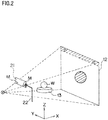
- FIG. 2 is a schematic diagram explaining the positions of markers M on the detection surface of an X-ray detector 12.
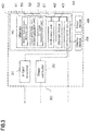
- FIG. 3 is a block diagram explaining a main control system of the X-ray CT device according to the present invention.
- the X-ray CT device includes: an X-ray source 11 that generates X-rays; the X-ray detector 12 arranged opposite to the X-ray source 11; a rotating stage 13 for placing a subject W; and a control device 30 that controls the whole of the X-ray CT device.
- the control device 30 is configured to include a personal computer 40, an X-ray controller 31, and a stage controller 32.
- the X-ray source 11 and the X-ray detector 12 are fixed to a surface plate 16 by an unillustrated support mechanism. Between the X-ray source 11 and the X-ray detector 12, the rotating stage 13 that rotates around a rotational axis R is arranged. The rotating stage 13 is moved in a direction along an X-ray optical axis on the surface plate 16 by a stage moving mechanism 15. By changing the distance between the rotating stage 13 and the X-ray source 11 by the stage moving mechanism 15, the enlargement ratio of a projection image of the subject W detected by the X-ray detector 12 is changed. Note that in this specification, as illustrated in FIG.
- an X-axis corresponds to the horizontal direction along the X-ray optical axis, a Z-axis to the up-down (vertical) direction, and a Y-axis to a direction orthogonal to the X-axis and the Z-axis.
- the X-ray source 11 has an X-ray tube that conically irradiates the subject W with X-rays toward the X-ray detector 12. Depending on the material and X-ray transmission properties of the subject W, tube voltage and tube current to be supplied to the X-ray tube are controlled by the X-ray controller 31.
- the X-ray controller 31 is under control of the personal computer 40.
- a transmitted X-ray image detected by the X-ray detector 12 is taken into the personal computer 40.
- a tomographic image that is a slice image along a surface parallel to the X-Y plane orthogonal to the rotational axis R is constructed by a CT image reconstruction part 53 (see FIG. 3 ).
- the rotating stage 13 and the stage moving mechanism 15 respectively have independent driving motors, and the driving motors are controlled by drive signals supplied from the stage controller 32.
- the stage controller 32 is under control of the personal computer 40.
- a marker member 20 including a flat plate 21 formed with the markers M and a support part 22 supporting the flat plate 21 is arranged between the X-ray source 11 and the rotating stage 13.
- the marker member 20 is arranged at a position closer to the X-ray source 11 than the rotating stage 13.
- the flat plate 21 is formed of a thin plate having a thickness enough to prevent deformation in a state of being supported by the support part 22.
- the flat plate 21 is provided with the markers M at two positions.
- the markers M are through-holes drilled at left-right symmetric positions of the flat plate 21 of a rectangular shape.
- columnar-shaped or truncated cone-shaped members formed of a material that is similar to the material of the flat plate 21 and attenuates X-rays may be disposed on the surface of the flat plate 21 as the markers M.
- the through-holes are not limited to columnar holes but may be tapered holes whose inner surfaces are tilted.
- the markers M may be formed on the flat plate 21 as the markers M, and depending on the material of the flat plate 21, voids may be provided inside the flat plate as the markers M. That is, the markers M only have to be ones capable of obtaining contrast with the flat plate 21 on a projection image by having a thickness different from that of the flat plate 21, and the shape of the markers M only have to be one causing a clear difference in X-ray transmission intensity between the plate part and marker parts of the flat plate 21. Also, in the present embodiment, the markers M are provided at the two positions, but the number of markers M may be further increased.
- the flat plate 21 is fixed to the support part 22 to prevent a change in installation angle.
- the position of marker member 21 is fixed to the side closer to the X-ray source 11 so that the markers M are included within the detection range of the X-ray detector 12.
- the flat plate 21 is fixed at a position close to the front of an X-ray irradiation port of the X-ray source 11.
- the length of the support part 22 determining the position of the flat plate 21 is set to a length so that a projection image of the flat plate 21 including the markers M is positioned at a side end of the detection range of the X-ray detector 12 where the projection image of the flat plate 21 is not superimposed on a projection image of the subject W.
- X-rays transmitted through the flat plate 21 and the subject W on the rotating stage 13 after conical irradiation from the X-ray focal point are detected by the X-ray detector 12 and the resulting detection data is inputted to the personal computer 40.
- the personal computer 40 includes: a memory 41 including a RAM, a ROM, and the like; an arithmetic unit 42 that performs various types of arithmetic processing, such as a CPU; a storage device 43 that stores projection data acquired as a result of a CT scan, such as an HDD; and a communication part 44 for transmitting control signals to the X-ray controller 31 and the stage controller 32.
- the memory 41, the arithmetic unit 42, the storage device 43, and the communication part 44 are connected via an internal bus enabling mutual data communication.
- the memory 41 stores a program for operating the arithmetic unit 42 to implement functions. In FIG. 3 , the program installed in the personal computer 40 is illustrated as a functional block.
- the functional block includes a marker feature point detection part 51, a focal point movement amount calculation part 52, and the CT image reconstruction part 53.
- the personal computer 40 is connected via the communication part 44 with a display device 48 that displays a tomographic image constructed by the operation of the arithmetic unit 42, or the like, and an input device 49 including a mouse, a keyboard, and the like for giving various instructions to the device.
- FIG. 4 is a flowchart illustrating a process from acquisition of a projection image of the markers M to CT image reconstruction.
- the marker member 20 is fixed to the surface plate 16 so that the flat plate 21 formed with the markers M is arranged just before the X-ray irradiation port of the X-ray source 11 (Step S11).
- the marker member 20 is fixed in such a manner as to parallelize the detection surface of the X-ray detector 12 and the plate surfaces of the flat plate 21. In doing so, the positions of the markers M and the installation angle of the flat plate 21 with respect to the detection surface of the X-ray detector 12 are fixed.
- an X-ray focal position reference focal position serving as a reference for the X-ray focal point is determined (Step S12).
- the X-ray focal position refers to a position where thermal electrons collide with a target to generate X-rays in the X-ray tube of the X-ray source 11, and is regarded as one point in this specification.
- the projection image of the markers M at the reference focal position is acquired (Step S13), and from the acquired projection image, the feature points of the markers M are detected (Step S14). That is, before starting the CT scan on the subject W, the positions of the feature points of the markers M (reference marker feature points) at the X-ray focal position serving as a reference before the X-ray tube is thermally deformed are acquired.
- the feature points of the markers M are points at which straight lines through the X-ray focal point and the markers M intersect with the detection surface of the X-ray detector 12.
- Luminance barycentric points on the projection image of the markers M determined by performing image processing on the projection image obtained by the X-ray detector 12 are set as the coordinates of the feature points. Note that the luminance barycentric points on the projection image of the markers M are points on the two-dimensional X-ray image, and the movements of the feature points of the markers M are represented by vectors in u-v plane coordinates corresponding to the detection surface of the X-ray detector 12.
- the scan is performed while simultaneously imaging the subject W and the markers M (Step S15).
- a projection image inputted from the X-ray detector 12 to the personal computer 40 at intervals of a predetermined rotation angle is stored in the storage device 43 as frame data.
- the frame data refers to one screen of projection image data, and is stored in the storage device 43 in order of acquisition time.
- the feature points of the markers M are detected (Step S16).
- pieces of projection data corresponding to a sampling pitch suitable for the number of views set in a set scan mode are collected.
- the subject W is irradiated with X-rays from multiple angles; however, since the position of the flat plate 21 with respect to the X-ray detector 12 is fixed, a projection image of the markers M is obtained from each frame.
- Step S16 When the X-ray focal position is moved due to some causes such as thermal deformation of the X-ray tube along with the progress of the scan, the movement can be observed as the movements of the feature points of the markers M in the u-v plane coordinates corresponding to the detection surface of the X-ray detector 12.
- the detection of the feature points of the markers M can be performed on all pieces of frame data, or on pieces of frame data extracted at predetermined intervals. That is, in Step S17 described below, it is only necessary to calculate how fat the feature points of the markers M are moved between two different frames.
- Step S14 and Step S16 the detection of the feature points of the markers M in Step S14 and Step S16 is performed in such a manner that the arithmetic unit 42 executes a program read from the marker feature point detection part 51 in the memory 41.
- Step S17 From the vectors of the feature points of the markers M obtained in Step S14 when the X-ray focal point is at the reference position, and the vectors of the feature points of the markers M in some frame obtained in Step S16 during the CT scan, how far and in which direction the feature points were moved are obtained (Step S17). In other words, from changes in the coordinate positions of the feature points of the markers M after the elapse of a certain time, how far and in which direction the X-ray focal point was moved within the certain time are calculated. The calculation of the X-ray focal point movement amount is performed in such a manner that the arithmetic unit 42 executes a program read from the focal point movement amount calculation part 52 in the memory 41.
- the positions of the feature points of the two markers M are obtained, and from the positional relationship between the two markers M and the movement amounts of the feature points of the respective markers M, the movement of the X-ray focal point in the direction (X direction) along the X-ray optical axis can also be calculated.
- the movement amount of the X-ray focal points within a corresponding time can be three-dimensionally calculated including a direction of the movement.
- the plate surfaces of the flat plate 21 is installed substantially parallel to the detection surface of the X-ray detector 12 during the CT scan. For this reason, when calculating the movement amount of the X-ray focal point, the movement amount of the X-ray focal point during the CT scan can be calculated without particularly setting installation angle information as a parameter.
- the installation angle of the flat plate 21 with respect to the detection surface of the X-ray detector 12 can also be added as a parameter.
- the installation angle of the flat plate 21 with respect to the detection surface of the X-ray detector 12 is more displaced from the parallel state, larger differences occur in the distances between the respective two markers M and the detection surface of the X-ray detector 12, and an enlargement ratio is made different between both on a projection image.
- the installation angle of the flat plate 21 with respect to the detection surface of the X-ray detector 12 only has to be acquired using a laser displacement meter or the like, for example, when the marker member 20 is fixed to the surface plate 16.
- a laser displacement meter or the like for example, when the marker member 20 is fixed to the surface plate 16.
- the installation angle is not changed during the use of the X-ray CT device, and therefore the acquisition of the installation angle information using the laser displacement meter or the like can be completed at one time.
- a coordinate system for the CT image reconstruction is corrected on the basis of the focal point movement amount (Step S18).
- the position of the X-ray focal point is one of the pieces of geometric information necessary to reconstruct the tomographic image, and by correcting the coordinate system for the CT image reconstruction on the basis of the focal point movement amount, an error in the geometric information during the CT scan is corrected.
- the CT image reconstruction is performed (Step S19) to reconstruct a tomographic image of the subject W.
- the correction of the coordinate system for the CT image reconstruction (Step S18) and the performance of the CT image reconstruction (Step 19) are achieved in such a manner that the arithmetic unit 42 executes a program read from the CT image reconstruction part 53 in the memory 41.
- the X-ray CT device of the present invention three-dimensionally detects the position of the X-ray focal point during the CT scan by performing the CT scan while simultaneously imaging at least the two markers M together with the subject W and detecting the feature points of the markers M along the same time axis as that for projection data on the subject W.
- This enables the movement of the X-ray focal point during the CT scan to be reflected in the reconstruction of the tomographic image, and therefore the tomographic image can be reconstructed without spatial distortion.
- the X-ray CT device of the present invention can also be used for three-dimensional shape measurement requiring high dimensional measurement accuracy.
Landscapes
- Health & Medical Sciences (AREA)
- Engineering & Computer Science (AREA)
- Nuclear Medicine, Radiotherapy & Molecular Imaging (AREA)
- Pulmonology (AREA)
- Radiology & Medical Imaging (AREA)
- Theoretical Computer Science (AREA)
- Physics & Mathematics (AREA)
- Life Sciences & Earth Sciences (AREA)
- Chemical & Material Sciences (AREA)
- Analytical Chemistry (AREA)
- Biochemistry (AREA)
- General Health & Medical Sciences (AREA)
- General Physics & Mathematics (AREA)
- Immunology (AREA)
- Pathology (AREA)
- Analysing Materials By The Use Of Radiation (AREA)
- Apparatus For Radiation Diagnosis (AREA)
Abstract
Description
- The present invention relates to an X-ray CT device that non-destructively observes the internal structures of various products and measures the three-dimensional shapes of the various products.
- An industrial X-ray CT device is one that three-dimensionally observes the internal structure of a subject such as an industrial product by, between an X-ray source and an X-ray detector that are mutually oppositely arranged, arranging a rotating stage on which the subject is placed, and collecting pieces of X-ray projection data from respective directions around the subject to reconstruct a tomographic image (see Patent Literature 1). The X-ray CT device is characterized by being able to capture such a three-dimensional structure of the subject, and therefore, in recent years, has been used not only for observation but for three-dimensional shape measurement.
- A tomographic image is reconstructed by back projecting projection images on the basis of geometric information on an X-ray focal point, a subject, and a detector at the time of a CT scan. For this reason, in an X-ray CT device for three-dimensional shape measurement, an error occurring in the geometric information causes spatial distortion in the reconstructed image, causing a reduction in dimensional measurement accuracy. In particular, the X-ray focal point is constantly varied due to some causes such as thermal expansion of an X-ray tube and deterioration of a target during X-ray irradiation. For example, if the X-ray focal point is varied by 10 µm, an error of 1 mm appears in a 100-times enlarged projection image detected by the X-ray detector. In order to reconstruct a tomographic image of a subject without spatial distortion in such a manner as to be able to achieve the dimensional measurement accuracy to be satisfied by the X-ray CT device as one for three-dimensional shape measurement, it is necessary to three-dimensionally detect the position of an X-ray focal point during a CT scan to correct information necessary to reconstruct a tomographic image or suppress a variation in X-ray focal point.
- Patent Literatures 2 and 3, and Non-Patent Literature 1 describe techniques for obtaining a two-dimensional focal point movement amount from projection images of a marker as a method for detecting the position of an X-ray focal point during a CT scan. Also, Patent Literature 4 describes a structure for, in order to suppress a reduction in detection accuracy due to the effect of a change in the temperature of a device, containing an X-ray source in a housing and supplying temperature-controlled gas into the housing to thereby cool the heat of the housing including the X-ray source.
-
- Patent Literature 1: Japanese Unexamined Patent Application Publication No.
2005-351879 - Patent Literature 2: International Publication No.
2009/036983 - Patent Literature 3: Japanese Patent No.
3743594 - Patent Literature 4: Japanese Patent No.
5850059 - Non-Patent Literature 1: Frederik Vogeler, Wesley Verheecke, Andre Voet, Jean-Pierre Kruth, Wim Dewulf, Positional Stability of 2D X-ray Images for Computer Tomography, International Symposium on Digital Industrial Radiology and Computed Tomography - Mo. 3.3
- In the case of position detection of an X-ray focal point described in Patent Literature 2, a projection image of a marker obtained via a detector is large to cause the marker to obstruct an imaging visual field of a subject, and therefore the subject and the marker cannot be simultaneously imaged. For this reason, when scanning the subject, the marker is withdrawn. Also, when imaging the marker, the arrangement of the marker at a reference position has to be reproduced so that the positional relationship between the marker and a detector is constant. For this reason, a highly accurate marker positioning mechanism is required, exerting a heavy load on fabrication.
- In the case of position detection of an X-ray focal point described in Non-Patent Literature 1, the position of the X-ray focal point during a CT scan can be constantly detected by, in the vicinity of a rotating stage on which a subject is placed, installing a marker in such a manner as to prevent the obstruction of the visual field of the subject, and simultaneously imaging the marker and the subject. However, the position of the X-ray focal point to be detected is only from two directions on a detector surface.
- In the case of position detection of an X-ray focal point described in Patent Literature 3, a projection image of a marker and a subject can be simultaneously taken by pasting the marker on the subject, and the position of the X-ray focal point during a CT scan can be constantly detected. However, the projection image obtained via a detector is one in which the marker is superimposed on the subject, so that the detection accuracy of the marker is reduced and also the marker affects a tomographic image of the subject.
- Also, even when temperature on an X-ray source side is controlled to suppress a variation in X-ray focal point, employing a structure for containing an X-ray source in a housing to fix it and further connecting the housing to a cooling device as described in Patent Literature 4 results in an increase in device fabrication cost.
- The present invention has been made in order to solve the above-described problems, and intends to provide an X-ray CT device capable of three-dimensionally detecting the position of an X-ray focal point, which varies during a CT scan of a subject, and reconstructing a tomographic image without spatial distortion.
- A first aspect of the present invention is an X-ray CT device that reconstructs a tomographic image of a subject on a basis of projection data acquired by irradiating the subject with X-rays from multiple angles, and the X-ray CT device includes: an X-ray source that generates an X-ray; an X-ray detector that is arranged opposite to the X-ray source and for detecting an X-ray; a rotating stage that is arranged between the X-ray source and the X-ray detector and for placing the subject; a control device that performs arithmetic processing on a basis of the projection data on the subject, the projection data being detected by the X-ray detector; and a marker member that includes a flat plate provided with markers at at least two positions and a support part supporting the flat plate and is arranged at a position that is between the rotating stage and the X-ray source, allows the markers to be included within a detection range of the X-ray detector during performance of a CT scan, and prevents the flat plate from being superimposed on a projection image of the subject. In addition, the control device includes: a marker feature point detection part that performs image processing on a projection image of the markers to thereby detect feature points that are points at which straight lines through a focal point of the X-ray source and the markers intersect with the X-ray detector, and obtains coordinates of the feature points on a two-dimensional X-ray image; and a focal point movement amount calculation part that, with use of coordinates of the feature points in two different frames, the coordinates being obtained by the marker feature point detection part, three-dimensionally calculates a movement amount of the focal point of the X-ray source between the two different frames, and on the basis of the movement amount of the focal point of the X-ray source, corrects a coordinate system at a time of reconstructing the tomographic image of the subject.
- A second aspect of the present invention is the X-ray CT device according to the first aspect, in which the marker member is fixed preventing an installation angle of the flat plate with respect to the X-ray detector from being changed, and the focal point movement amount calculation part three-dimensionally calculates the movement amount of the focal point of the X-ray source with use of installation angle information on the flat plate.
- A third aspect of the present invention is the X-ray CT device according to the first aspect, in which the marker member is arranged with the flat plate brought close to an X-ray irradiation port of the X-ray source.
- A fourth aspect of the present invention is the X-ray CT device according to the first aspect, in which the marker feature point detection part performs image processing on the projection image of the markers to obtain luminous barycentric points and determines the luminous barycentric points as the coordinates of the feature points.
- A fifth aspect of the present invention is the X-ray CT device according to the first aspect, in which the flat plate of the marker member is made of a material that attenuates an X-ray.
- A sixth aspect of the present invention is the X-ray CT device according to the fifth aspect, in which the markers are voids provided inside the flat plate or through-holes or concave parts formed in the flat plate.
- A seventh aspect of the present invention is the X-ray CT device according to the fifth aspect, in which the markers are columnar-shaped or truncated cone-shaped members that are disposed on a surface of the flat plate and made of a material that attenuates an X-ray.
- According to the first to seventh aspects of the present invention, the X-ray CT device includes the marker member having the flat plate formed with the markers at at least two positions for detecting the position of the X-ray focal point, simultaneously scans the at least two markers without superimposing them on the projection image of the subject, three-dimensionally detects the position of the X-ray focal point during the CT scan, and on the basis of the movement amount of the focal point of the X-ray source, and corrects the coordinate system at the time of reconstructing the tomographic image, and can therefore reconstruct the tomographic image without spatial distortion. For this reason, the X-ray CT device can achieve high dimensional measurement accuracy as a device for three-dimensional shape measurement.
- According to the second aspect of the present invention, by fixing the installation angle of the flat plate with respect to the X-ray detector and adding the installation angle as a calculation parameter for the movement amount of the X-ray focal point, the position of the X-ray focal point during the CT scan can be more accurately obtained.
- According to the third aspect of the present invention, since the marker member is arranged with the flat plate brought close to the X-ray irradiation port of the X-ray source, the enlargement ratio of the markers on a projection image can be increased. This enables the size of the markers provided on the flat plate to be reduced.
- According to the fourth aspect of the present invention, since the luminous barycentric points are determined as the coordinates of the feature points by performing the image processing on the projection image of the markers, the coordinates of the feature points can be accurately determined even when the projection image of the markers is deformed.
- According to the fifth to seventh aspects of the present invention, by providing the markers having a thickness different from that of the flat plate, X-ray transmission intensity can be made clearly different between the plate part and marker parts of the flat plate on a projection image to easily perform the detection of the feature points by the image processing.
- According to the sixth aspect of the present invention, the markers can be easily formed on the flat plate.
-
-
FIG. 1 is a schematic diagram of the X-ray CT device according to the present invention; -
FIG. 2 is a schematic diagram explaining the positions of markers M on the detection surface of anX-ray detector 12; -
FIG. 3 is a block diagram explaining a main control system of the X-ray CT device according to the present invention: and -
FIG. 4 is a flowchart illustrating a process from acquisition of a projection image of the markers M to CT image reconstruction. - An embodiment of the present invention will be described with reference to the drawings.
FIG. 1 is a schematic diagram of the X-ray CT device according to the present invention.FIG. 2 is a schematic diagram explaining the positions of markers M on the detection surface of anX-ray detector 12.FIG. 3 is a block diagram explaining a main control system of the X-ray CT device according to the present invention. - The X-ray CT device includes: an
X-ray source 11 that generates X-rays; theX-ray detector 12 arranged opposite to theX-ray source 11; arotating stage 13 for placing a subject W; and acontrol device 30 that controls the whole of the X-ray CT device. Thecontrol device 30 is configured to include apersonal computer 40, anX-ray controller 31, and astage controller 32. - The
X-ray source 11 and theX-ray detector 12 are fixed to asurface plate 16 by an unillustrated support mechanism. Between theX-ray source 11 and theX-ray detector 12, the rotatingstage 13 that rotates around a rotational axis R is arranged. The rotatingstage 13 is moved in a direction along an X-ray optical axis on thesurface plate 16 by astage moving mechanism 15. By changing the distance between therotating stage 13 and theX-ray source 11 by thestage moving mechanism 15, the enlargement ratio of a projection image of the subject W detected by theX-ray detector 12 is changed. Note that in this specification, as illustrated inFIG. 2 , an X-axis corresponds to the horizontal direction along the X-ray optical axis, a Z-axis to the up-down (vertical) direction, and a Y-axis to a direction orthogonal to the X-axis and the Z-axis. - The
X-ray source 11 has an X-ray tube that conically irradiates the subject W with X-rays toward theX-ray detector 12. Depending on the material and X-ray transmission properties of the subject W, tube voltage and tube current to be supplied to the X-ray tube are controlled by theX-ray controller 31. TheX-ray controller 31 is under control of thepersonal computer 40. A transmitted X-ray image detected by theX-ray detector 12 is taken into thepersonal computer 40. In thepersonal computer 40, a tomographic image that is a slice image along a surface parallel to the X-Y plane orthogonal to the rotational axis R is constructed by a CT image reconstruction part 53 (seeFIG. 3 ). - The
rotating stage 13 and thestage moving mechanism 15 respectively have independent driving motors, and the driving motors are controlled by drive signals supplied from thestage controller 32. Thestage controller 32 is under control of thepersonal computer 40. - Also, between the
X-ray source 11 and therotating stage 13, amarker member 20 including aflat plate 21 formed with the markers M and asupport part 22 supporting theflat plate 21 is arranged. Themarker member 20 is arranged at a position closer to theX-ray source 11 than therotating stage 13. - The
flat plate 21 is formed of a thin plate having a thickness enough to prevent deformation in a state of being supported by thesupport part 22. In addition, theflat plate 21 is provided with the markers M at two positions. In the present embodiment, the markers M are through-holes drilled at left-right symmetric positions of theflat plate 21 of a rectangular shape. Note that in place of the through-holes, columnar-shaped or truncated cone-shaped members formed of a material that is similar to the material of theflat plate 21 and attenuates X-rays may be disposed on the surface of theflat plate 21 as the markers M. In addition, in terms of shape, the through-holes are not limited to columnar holes but may be tapered holes whose inner surfaces are tilted. Further, not the through-holes but concave parts may be formed on theflat plate 21 as the markers M, and depending on the material of theflat plate 21, voids may be provided inside the flat plate as the markers M. That is, the markers M only have to be ones capable of obtaining contrast with theflat plate 21 on a projection image by having a thickness different from that of theflat plate 21, and the shape of the markers M only have to be one causing a clear difference in X-ray transmission intensity between the plate part and marker parts of theflat plate 21. Also, in the present embodiment, the markers M are provided at the two positions, but the number of markers M may be further increased. - The
flat plate 21 is fixed to thesupport part 22 to prevent a change in installation angle. When irradiating the subject W with X-rays from the focal point of theX-ray source 11 to acquire projection data on the subject W, as illustrated inFIG. 2 , the position ofmarker member 21 is fixed to the side closer to theX-ray source 11 so that the markers M are included within the detection range of theX-ray detector 12. In doing so, theflat plate 21 is fixed at a position close to the front of an X-ray irradiation port of theX-ray source 11. In addition, as illustrated inFIG. 2 , the length of thesupport part 22 determining the position of theflat plate 21 is set to a length so that a projection image of theflat plate 21 including the markers M is positioned at a side end of the detection range of theX-ray detector 12 where the projection image of theflat plate 21 is not superimposed on a projection image of the subject W. By arranging themarker member 20 to thesurface plate 16 via thesupport part 22 as described, theflat plate 21 formed with the markers M can be fixed at the fixed position independently of a casing of theX-ray source 11. - Regarding the formation positions of the markers M on the
flat plate 21, by increasing the separation distance between the markers M within a range where both of the markers M are not superimposed on the projection image of the subject W, the calculation accuracy of the below-described three-dimensional movement amount of the X-ray focal point is improved. - X-rays transmitted through the
flat plate 21 and the subject W on therotating stage 13 after conical irradiation from the X-ray focal point are detected by theX-ray detector 12 and the resulting detection data is inputted to thepersonal computer 40. - The
personal computer 40 includes: amemory 41 including a RAM, a ROM, and the like; anarithmetic unit 42 that performs various types of arithmetic processing, such as a CPU; astorage device 43 that stores projection data acquired as a result of a CT scan, such as an HDD; and acommunication part 44 for transmitting control signals to theX-ray controller 31 and thestage controller 32. Thememory 41, thearithmetic unit 42, thestorage device 43, and thecommunication part 44 are connected via an internal bus enabling mutual data communication. Thememory 41 stores a program for operating thearithmetic unit 42 to implement functions. InFIG. 3 , the program installed in thepersonal computer 40 is illustrated as a functional block. In the present embodiment, the functional block includes a marker featurepoint detection part 51, a focal point movementamount calculation part 52, and the CTimage reconstruction part 53. Also, thepersonal computer 40 is connected via thecommunication part 44 with adisplay device 48 that displays a tomographic image constructed by the operation of thearithmetic unit 42, or the like, and aninput device 49 including a mouse, a keyboard, and the like for giving various instructions to the device. - Next, a procedure for detecting the position of the X-ray focal point during the CT scan when the X-ray CT device having the above-described configuration performs the CT scan will be described. A tomographic image is reconstructed by back projecting projection images on the basis of pieces of geometric information including a positional relationship among the X-ray focal point, the subject W, and the detector at the time of the CT scan. Accordingly, the present invention is adapted to track the positional movement of the X-ray focal point, which is one of the pieces of geometric information necessary to reconstruct the tomographic image, and reflect the resulting movement amount in the reconstruction of the tomographic image.
FIG. 4 is a flowchart illustrating a process from acquisition of a projection image of the markers M to CT image reconstruction. - First, the
marker member 20 is fixed to thesurface plate 16 so that theflat plate 21 formed with the markers M is arranged just before the X-ray irradiation port of the X-ray source 11 (Step S11). At this time, themarker member 20 is fixed in such a manner as to parallelize the detection surface of theX-ray detector 12 and the plate surfaces of theflat plate 21. In doing so, the positions of the markers M and the installation angle of theflat plate 21 with respect to the detection surface of theX-ray detector 12 are fixed. Then, an X-ray focal position (reference focal position) serving as a reference for the X-ray focal point is determined (Step S12). Note that the X-ray focal position refers to a position where thermal electrons collide with a target to generate X-rays in the X-ray tube of theX-ray source 11, and is regarded as one point in this specification. - The projection image of the markers M at the reference focal position is acquired (Step S13), and from the acquired projection image, the feature points of the markers M are detected (Step S14). That is, before starting the CT scan on the subject W, the positions of the feature points of the markers M (reference marker feature points) at the X-ray focal position serving as a reference before the X-ray tube is thermally deformed are acquired.
- The feature points of the markers M are points at which straight lines through the X-ray focal point and the markers M intersect with the detection surface of the
X-ray detector 12. Luminance barycentric points on the projection image of the markers M determined by performing image processing on the projection image obtained by theX-ray detector 12 are set as the coordinates of the feature points. Note that the luminance barycentric points on the projection image of the markers M are points on the two-dimensional X-ray image, and the movements of the feature points of the markers M are represented by vectors in u-v plane coordinates corresponding to the detection surface of theX-ray detector 12. Also, by setting the coordinates of the feature points of the markers M to the luminance barycentric points, relationships with X-ray incident angles on the markers M make it possible to accurately obtain the coordinates of the feature points of the markers M even if the markers M of a circular shape formed on theflat plate 21 are deformed to those of an elliptic shape on the projection image. - Subsequently, the scan is performed while simultaneously imaging the subject W and the markers M (Step S15). When performing the CT scan, while performing the X-ray irradiation from the
X-ray source 11 and rotating therotating stage 13 on which the subject W is placed, a projection image inputted from theX-ray detector 12 to thepersonal computer 40 at intervals of a predetermined rotation angle is stored in thestorage device 43 as frame data. Note that the frame data refers to one screen of projection image data, and is stored in thestorage device 43 in order of acquisition time. - By performing the image processing on an acquired projection image, the feature points of the markers M are detected (Step S16). During the CT scan, pieces of projection data corresponding to a sampling pitch suitable for the number of views set in a set scan mode are collected. During the scan, the subject W is irradiated with X-rays from multiple angles; however, since the position of the
flat plate 21 with respect to theX-ray detector 12 is fixed, a projection image of the markers M is obtained from each frame. When the X-ray focal position is moved due to some causes such as thermal deformation of the X-ray tube along with the progress of the scan, the movement can be observed as the movements of the feature points of the markers M in the u-v plane coordinates corresponding to the detection surface of theX-ray detector 12. By performing the image processing on pieces of frame data, the feature points of the markers M in the two different frames are detected (Step S16). The detection of the feature points of the markers M can be performed on all pieces of frame data, or on pieces of frame data extracted at predetermined intervals. That is, in Step S17 described below, it is only necessary to calculate how fat the feature points of the markers M are moved between two different frames. - In addition, the detection of the feature points of the markers M in Step S14 and Step S16 is performed in such a manner that the
arithmetic unit 42 executes a program read from the marker featurepoint detection part 51 in thememory 41. - From the vectors of the feature points of the markers M obtained in Step S14 when the X-ray focal point is at the reference position, and the vectors of the feature points of the markers M in some frame obtained in Step S16 during the CT scan, how far and in which direction the feature points were moved are obtained (Step S17). In other words, from changes in the coordinate positions of the feature points of the markers M after the elapse of a certain time, how far and in which direction the X-ray focal point was moved within the certain time are calculated. The calculation of the X-ray focal point movement amount is performed in such a manner that the
arithmetic unit 42 executes a program read from the focal point movementamount calculation part 52 in thememory 41. - In addition, in the present embodiment, the positions of the feature points of the two markers M are obtained, and from the positional relationship between the two markers M and the movement amounts of the feature points of the respective markers M, the movement of the X-ray focal point in the direction (X direction) along the X-ray optical axis can also be calculated. As described, using the coordinates of the feature points of at least the two markers M detected in two different frames, the movement amount of the X-ray focal points within a corresponding time can be three-dimensionally calculated including a direction of the movement.
- In this X-ray CT device, the plate surfaces of the
flat plate 21 is installed substantially parallel to the detection surface of theX-ray detector 12 during the CT scan. For this reason, when calculating the movement amount of the X-ray focal point, the movement amount of the X-ray focal point during the CT scan can be calculated without particularly setting installation angle information as a parameter. - Incidentally, when three-dimensionally calculating the movement amount of the X-ray focal point, the installation angle of the
flat plate 21 with respect to the detection surface of theX-ray detector 12 can also be added as a parameter. As the installation angle of theflat plate 21 with respect to the detection surface of theX-ray detector 12 is more displaced from the parallel state, larger differences occur in the distances between the respective two markers M and the detection surface of theX-ray detector 12, and an enlargement ratio is made different between both on a projection image. By using the installation angle information preliminarily acquired as a known parameter to detect the spatial movement of the X-ray focal point, the detection accuracy of the movement of the X-ray focal point can be further improved. - The installation angle of the
flat plate 21 with respect to the detection surface of theX-ray detector 12 only has to be acquired using a laser displacement meter or the like, for example, when themarker member 20 is fixed to thesurface plate 16. In addition, as in this X-ray CT device, in the case where the positions of theX-ray source 11 andX-ray detector 12 are fixed, and the position of themarker member 21 during the CT scan is fixed with respect to thesurface plate 16, once theX-ray detector 12 and themarker member 20 are arranged, the installation angle is not changed during the use of the X-ray CT device, and therefore the acquisition of the installation angle information using the laser displacement meter or the like can be completed at one time. - When the movement amount of the X-ray focal point is obtained, a coordinate system for the CT image reconstruction is corrected on the basis of the focal point movement amount (Step S18). The position of the X-ray focal point is one of the pieces of geometric information necessary to reconstruct the tomographic image, and by correcting the coordinate system for the CT image reconstruction on the basis of the focal point movement amount, an error in the geometric information during the CT scan is corrected. After that, the CT image reconstruction is performed (Step S19) to reconstruct a tomographic image of the subject W. In addition, the correction of the coordinate system for the CT image reconstruction (Step S18) and the performance of the CT image reconstruction (Step 19) are achieved in such a manner that the
arithmetic unit 42 executes a program read from the CTimage reconstruction part 53 in thememory 41. - As described above, the X-ray CT device of the present invention three-dimensionally detects the position of the X-ray focal point during the CT scan by performing the CT scan while simultaneously imaging at least the two markers M together with the subject W and detecting the feature points of the markers M along the same time axis as that for projection data on the subject W. This enables the movement of the X-ray focal point during the CT scan to be reflected in the reconstruction of the tomographic image, and therefore the tomographic image can be reconstructed without spatial distortion. Accordingly, the X-ray CT device of the present invention can also be used for three-dimensional shape measurement requiring high dimensional measurement accuracy.
-
- 11: X-ray source
- 12: X-ray detector
- 13: Rotating stage
- 15: Stage moving mechanism
- 16: Surface plate
- 20: Marker member
- 21: Flat plate
- 22: Support part
- 30: Control device
- 31: X-ray controller
- 32: Stage controller
- 40: Personal computer
- 41: Memory
- 42: Arithmetic unit
- 43: Storage device
- 44: Communication part
- 48: Display device
- 49: Input device
- 51: Marker feature point detection part
- 52: Focal point movement amount calculation part
- 53: CT image reconstruction part
- M: Marker
- W: Subject
Claims (7)
- An X-ray CT device that reconstructs a tomographic image of a subject on a basis of projection data acquired by irradiating the subject with X-rays from multiple angles, the X-ray CT device comprising:an X-ray source that generates an X-ray;an X-ray detector that is arranged opposite to the X-ray source and for detecting an X-ray;a rotating stage that is arranged between the X-ray source and the X-ray detector and for placing the subject;a control device that performs arithmetic processing on a basis of the projection data on the subject, the projection data being detected by the X-ray detector; anda marker member that includes a flat plate provided with markers at at least two positions and a support part supporting the flat plate and is arranged at a position that is between the rotating stage and the X-ray source, allows the markers to be included within a detection range of the X-ray detector during performance of a CT scan, and prevents the flat plate from being superimposed on a projection image of the subject, whereinthe control device comprises:a marker feature point detection part that performs image processing on a projection image of the markers to thereby detect feature points that are points at which straight lines through a focal point of the X-ray source and the markers intersect with the X-ray detector, and obtains coordinates of the feature points on a two-dimensional X-ray image; anda focal point movement amount calculation part that, with use of coordinates of the feature points in two different frames, the coordinates being obtained by the marker feature point detection part, three-dimensionally calculates a movement amount of the focal point of the X-ray source between the two different frames, andon the basis of the movement amount of the focal point of the X-ray source, corrects a coordinate system at a time of reconstructing the tomographic image of the subject.
- The X-ray CT device according to claim 1, wherein
the marker member is fixed preventing an installation angle of the flat plate with respect to the X-ray detector from being changed, and
the focal point movement amount calculation part three-dimensionally calculates the movement amount of the focal point of the X-ray source with use of installation angle information on the flat plate. - The X-ray CT device according to claim 1, wherein
the marker member is arranged with the flat plate brought close to an X-ray irradiation port of the X-ray source. - The X-ray CT device according to claim 1, wherein
the marker feature point detection part performs the image processing on the projection image of the markers to obtain luminous barycentric points and determines the luminous barycentric points as the coordinates of the feature points. - The X-ray CT device according to claim 1, wherein
the flat plate of the marker member is made of a material that attenuates an X-ray. - The X-ray CT device according to claim 5, wherein
the markers are voids provided inside the flat plate or through-holes or concave parts formed in the flat plate. - The X-ray CT device according to claim 5, wherein
the markers are columnar-shaped or truncated cone-shaped members that are disposed on a surface of the flat plate and made of a material that attenuates an X-ray.
Applications Claiming Priority (1)
| Application Number | Priority Date | Filing Date | Title |
|---|---|---|---|
| PCT/JP2017/024319 WO2019008620A1 (en) | 2017-07-03 | 2017-07-03 | X-ray ct device |
Publications (3)
| Publication Number | Publication Date |
|---|---|
| EP3620778A1 true EP3620778A1 (en) | 2020-03-11 |
| EP3620778A4 EP3620778A4 (en) | 2020-08-19 |
| EP3620778B1 EP3620778B1 (en) | 2025-09-03 |
Family
ID=64949871
Family Applications (1)
| Application Number | Title | Priority Date | Filing Date |
|---|---|---|---|
| EP17917158.2A Active EP3620778B1 (en) | 2017-07-03 | 2017-07-03 | X-ray ct device |
Country Status (6)
| Country | Link |
|---|---|
| US (1) | US11002690B2 (en) |
| EP (1) | EP3620778B1 (en) |
| JP (1) | JP7164524B2 (en) |
| CN (1) | CN110621985B (en) |
| TW (1) | TWI680293B (en) |
| WO (1) | WO2019008620A1 (en) |
Families Citing this family (14)
| Publication number | Priority date | Publication date | Assignee | Title |
|---|---|---|---|---|
| WO2019065701A1 (en) * | 2017-09-28 | 2019-04-04 | 株式会社サキコーポレーション | Inspection position specification method, three-dimensional image generation method, and inspection device |
| JP7143567B2 (en) * | 2018-09-14 | 2022-09-29 | 株式会社島津テクノリサーチ | Material testing machine and radiation CT equipment |
| KR102586361B1 (en) * | 2019-02-26 | 2023-10-11 | 고쿠리츠 다이가꾸 호우진 시즈오까 다이가꾸 | X-ray imaging device |
| JP2020186913A (en) * | 2019-05-09 | 2020-11-19 | 株式会社リガク | X-ray ct apparatus and ct image reconstruction method |
| CN111449668B (en) * | 2020-04-23 | 2023-06-23 | 深圳市安健科技股份有限公司 | Marking device, method and system for real-time geometric correction in three-dimensional scanning reconstruction |
| CN111812130A (en) * | 2020-07-15 | 2020-10-23 | 深圳市金园智能科技有限公司 | X-ray-based material interior 3D imaging method and device |
| JP7513980B2 (en) * | 2020-08-04 | 2024-07-10 | 東芝エネルギーシステムズ株式会社 | Medical image processing device, treatment system, medical image processing method, and program |
| CN114609684B (en) * | 2020-12-09 | 2025-03-25 | 同方威视技术股份有限公司 | Article detection methods, devices, security inspection equipment, media and program products |
| CN112842373A (en) * | 2020-12-31 | 2021-05-28 | 太丛信息科技(上海)有限公司 | CBCT (Cone Beam computed tomography) acquisition device and acquisition method for animals with different body types |
| CN114280086B (en) * | 2021-11-16 | 2024-01-23 | 中国电子科技集团公司第三十八研究所 | CT imaging device |
| CN114199905B (en) * | 2021-12-13 | 2024-02-20 | 中国航发南方工业有限公司 | A spatial positioning method and system for internal defects in the casing |
| WO2026079182A1 (en) * | 2024-10-09 | 2026-04-16 | 株式会社島津製作所 | X-ray imaging device |
| CN119146859B (en) * | 2024-11-12 | 2025-02-07 | 浙江省特种设备科学研究院 | Device and method for detecting drift of industrial CT detected sample |
| CN120948514B (en) * | 2025-10-13 | 2026-04-07 | 宁德时代新能源科技股份有限公司 | Battery cell image acquisition methods, devices, electronic equipment, storage media and software products |
Family Cites Families (35)
| Publication number | Priority date | Publication date | Assignee | Title |
|---|---|---|---|---|
| JP4054402B2 (en) | 1997-04-25 | 2008-02-27 | 株式会社東芝 | X-ray tomography equipment |
| JPS5850059B2 (en) | 1977-02-04 | 1983-11-08 | 日本電気株式会社 | Reception signal control circuit |
| JPS62284250A (en) * | 1986-05-31 | 1987-12-10 | Toshiba Corp | Industrial ct scanner |
| JP3743594B2 (en) | 1998-03-11 | 2006-02-08 | 株式会社モリタ製作所 | CT imaging device |
| JP3792432B2 (en) | 1999-04-14 | 2006-07-05 | 東芝Itコントロールシステム株式会社 | Computed tomography equipment |
| JP2002333408A (en) | 2001-05-08 | 2002-11-22 | Hitachi Medical Corp | Industrial x-ray ct device |
| AU2002332758A1 (en) * | 2001-08-31 | 2003-03-18 | Analogic Corporation | Image positioning method and system for tomosynthesis in a digital x-ray radiography system |
| DE10206190A1 (en) * | 2002-02-14 | 2003-09-04 | Siemens Ag | Method and device for generating a volume data set |
| JP2004340630A (en) | 2003-05-13 | 2004-12-02 | Sony Corp | Computer tomographic imaging method and apparatus |
| US7310404B2 (en) * | 2004-03-24 | 2007-12-18 | Canon Kabushiki Kaisha | Radiation CT radiographing device, radiation CT radiographing system, and radiation CT radiographing method using the same |
| JP4532949B2 (en) | 2004-03-24 | 2010-08-25 | キヤノン株式会社 | Radiation CT imaging apparatus, radiation CT imaging system, and radiation CT imaging method using the same |
| JP4375555B2 (en) | 2004-05-14 | 2009-12-02 | 株式会社島津製作所 | X-ray CT system |
| US7344307B2 (en) * | 2004-11-12 | 2008-03-18 | General Electric Company | System and method for integration of a calibration target into a C-arm |
| DE102005021020A1 (en) * | 2005-05-06 | 2006-11-16 | Siemens Ag | Method for calculating an orthogonal X-ray attenuation on an object table involves storing of object on a computer tomograph on the basis of a reference projection direction measured along reference X-ray attenuation |
| JP4601571B2 (en) * | 2006-03-20 | 2010-12-22 | ラトックシステムエンジニアリング株式会社 | X-ray inspection equipment |
| CN103961130B (en) * | 2006-09-25 | 2017-08-15 | 马佐尔机器人有限公司 | So that C-arm system adapts to the method to provide three-dimensional imaging information |
| US7835811B2 (en) * | 2006-10-07 | 2010-11-16 | Voxelogix Corporation | Surgical guides and methods for positioning artificial teeth and dental implants |
| AU2007322982A1 (en) * | 2006-10-23 | 2008-05-29 | Hirdesh Sahni | An image guided whole body stereotactic needle placement device with falling arc |
| DE102007043820B4 (en) * | 2007-09-13 | 2020-06-04 | Carl Zeiss Industrielle Messtechnik Gmbh | Method for determining a correction value of a brake spot position of an X-ray source of a measuring arrangement and a measuring arrangement for generating radiographic images |
| CN101398397B (en) * | 2007-09-30 | 2012-05-30 | 首都师范大学 | CT imaging method of multitime scanning mode |
| US8249213B2 (en) * | 2008-08-13 | 2012-08-21 | Koninklijke Philips Electronics N.V. | Calibration method for ring artifact correction in non-ideal isocentric 3D rotational X-ray scanner systems using a calibration phantom based rotation center finding algorithm |
| JP4853591B2 (en) * | 2008-12-01 | 2012-01-11 | 株式会社島津製作所 | Radiation imaging device |
| JP5400546B2 (en) * | 2009-09-28 | 2014-01-29 | 株式会社日立メディコ | X-ray CT system |
| JP5878117B2 (en) * | 2010-05-11 | 2016-03-08 | 株式会社テレシステムズ | Radiation imaging apparatus and phantom used in the apparatus |
| CN102652674B (en) * | 2011-03-04 | 2014-02-19 | 首都师范大学 | A method and system for removing geometric artifacts in CT images |
| US9693748B2 (en) * | 2011-07-23 | 2017-07-04 | Broncus Medical Inc. | System and method for automatically determining calibration parameters of a fluoroscope |
| DE102011083416A1 (en) * | 2011-09-26 | 2013-03-28 | CT Imaging GmbH | X-ray machine |
| WO2013051594A1 (en) | 2011-10-04 | 2013-04-11 | 株式会社ニコン | X-ray device, x-ray irradiation method, and manufacturing method for structure |
| JP6032729B2 (en) | 2012-05-08 | 2016-11-30 | 国立研究開発法人理化学研究所 | Imaging markers and their use |
| KR101823743B1 (en) * | 2014-01-23 | 2018-01-31 | 가부시키가이샤 죠부 | X-ray inspection apparatus and x-ray inspection method |
| JP2015215218A (en) | 2014-05-09 | 2015-12-03 | 株式会社島津製作所 | Radiation inspection apparatus |
| JP6394082B2 (en) * | 2014-06-09 | 2018-09-26 | 株式会社島津製作所 | X-ray inspection equipment |
| WO2016059673A1 (en) * | 2014-10-14 | 2016-04-21 | 株式会社リガク | X-ray thin film inspection device |
| JP2017086816A (en) | 2015-11-17 | 2017-05-25 | 東芝メディカルシステムズ株式会社 | X-ray computer tomography apparatus |
| CN106361367B (en) * | 2016-12-01 | 2019-10-08 | 上海联影医疗科技有限公司 | A kind of bearing calibration of detector and device and equipment using the bearing calibration |
-
2017
- 2017-07-03 EP EP17917158.2A patent/EP3620778B1/en active Active
- 2017-07-03 CN CN201780090704.4A patent/CN110621985B/en active Active
- 2017-07-03 US US16/605,551 patent/US11002690B2/en active Active
- 2017-07-03 WO PCT/JP2017/024319 patent/WO2019008620A1/en not_active Ceased
- 2017-07-03 JP JP2019528189A patent/JP7164524B2/en active Active
-
2018
- 2018-07-03 TW TW107122978A patent/TWI680293B/en not_active IP Right Cessation
Also Published As
| Publication number | Publication date |
|---|---|
| EP3620778B1 (en) | 2025-09-03 |
| CN110621985B (en) | 2022-03-11 |
| JPWO2019008620A1 (en) | 2020-02-27 |
| TW201907154A (en) | 2019-02-16 |
| US11002690B2 (en) | 2021-05-11 |
| JP7164524B2 (en) | 2022-11-01 |
| CN110621985A (en) | 2019-12-27 |
| US20200124545A1 (en) | 2020-04-23 |
| WO2019008620A1 (en) | 2019-01-10 |
| TWI680293B (en) | 2019-12-21 |
| EP3620778A4 (en) | 2020-08-19 |
Similar Documents
| Publication | Publication Date | Title |
|---|---|---|
| EP3620778B1 (en) | X-ray ct device | |
| US9014341B2 (en) | CT collimator and CT system including the CT collimator | |
| US8804912B2 (en) | Radiographic imaging apparatus, method and program | |
| US20030043962A1 (en) | Image positioning method and system for tomosynthesis in a digital X-ray radiography system | |
| JP6471151B2 (en) | X-ray inspection system and method for rotating a test object using such an X-ray inspection system | |
| JP2015518765A (en) | Motion layer resolution calibration of X-ray CT images | |
| JP2019128163A (en) | X-ray ct device for measurement and calibration method therefor | |
| US11417035B2 (en) | X-ray tomosynthesis apparatus, image processing apparatus, and program | |
| CN111141767A (en) | X-ray CT apparatus for measurement and CT reconstruction method using the same | |
| JPWO2018083930A1 (en) | Imaging magnification calibration method of radiation tomography apparatus | |
| CN117871557A (en) | Inspection device and method for determining inspection area | |
| CN112261908A (en) | X-ray system error tracking and calibration | |
| JP2021050937A (en) | Calibration method of x-ray ct scanner for measurement, measurement method, and x-ray ct scanner for measurement | |
| US20120027170A1 (en) | Radiological image capturing and displaying method and apparatus | |
| JP2015232453A (en) | X-ray inspection equipment | |
| JP7251602B2 (en) | X-ray CT device | |
| US20160183892A1 (en) | Method for imaging by means of an x-ray device and x-ray device | |
| JP2019164132A (en) | GEOMETRIC ALIGNMENT, SAMPLE MOTION CORRECTION, AND INTENSITY NORMALIZATION OF COMPUTED TOMOGRAPHY PROJECTIONS USING π-LINE OPTIMIZATION | |
| JP4818695B2 (en) | Radiographic imaging condition correction device | |
| US11022570B2 (en) | X-ray transmission inspection apparatus and X-ray transmission inspection method | |
| JP2015232958A (en) | Charged particle beam apparatus, three-dimensional image reconstruction image processing system and method | |
| JP2011191217A (en) | X-ray inspection method, x-ray inspection device, and x-ray inspection program | |
| JP2017205483A (en) | Marking method and computerized tomography apparatus | |
| JP4479503B2 (en) | Tomography equipment | |
| CN109475336A (en) | Geometric distortion correction method and device for chest tomosynthesis reconstruction |
Legal Events
| Date | Code | Title | Description |
|---|---|---|---|
| STAA | Information on the status of an ep patent application or granted ep patent |
Free format text: STATUS: THE INTERNATIONAL PUBLICATION HAS BEEN MADE |
|
| PUAI | Public reference made under article 153(3) epc to a published international application that has entered the european phase |
Free format text: ORIGINAL CODE: 0009012 |
|
| STAA | Information on the status of an ep patent application or granted ep patent |
Free format text: STATUS: REQUEST FOR EXAMINATION WAS MADE |
|
| 17P | Request for examination filed |
Effective date: 20191205 |
|
| AK | Designated contracting states |
Kind code of ref document: A1 Designated state(s): AL AT BE BG CH CY CZ DE DK EE ES FI FR GB GR HR HU IE IS IT LI LT LU LV MC MK MT NL NO PL PT RO RS SE SI SK SM TR |
|
| AX | Request for extension of the european patent |
Extension state: BA ME |
|
| A4 | Supplementary search report drawn up and despatched |
Effective date: 20200720 |
|
| RIC1 | Information provided on ipc code assigned before grant |
Ipc: G01N 23/046 20180101ALI20200714BHEP Ipc: G01N 23/04 20180101AFI20200714BHEP |
|
| DAV | Request for validation of the european patent (deleted) | ||
| DAX | Request for extension of the european patent (deleted) | ||
| STAA | Information on the status of an ep patent application or granted ep patent |
Free format text: STATUS: EXAMINATION IS IN PROGRESS |
|
| 17Q | First examination report despatched |
Effective date: 20220608 |
|
| GRAP | Despatch of communication of intention to grant a patent |
Free format text: ORIGINAL CODE: EPIDOSNIGR1 |
|
| STAA | Information on the status of an ep patent application or granted ep patent |
Free format text: STATUS: GRANT OF PATENT IS INTENDED |
|
| INTG | Intention to grant announced |
Effective date: 20250401 |
|
| GRAS | Grant fee paid |
Free format text: ORIGINAL CODE: EPIDOSNIGR3 |
|
| GRAA | (expected) grant |
Free format text: ORIGINAL CODE: 0009210 |
|
| STAA | Information on the status of an ep patent application or granted ep patent |
Free format text: STATUS: THE PATENT HAS BEEN GRANTED |
|
| AK | Designated contracting states |
Kind code of ref document: B1 Designated state(s): AL AT BE BG CH CY CZ DE DK EE ES FI FR GB GR HR HU IE IS IT LI LT LU LV MC MK MT NL NO PL PT RO RS SE SI SK SM TR |
|
| REG | Reference to a national code |
Ref country code: GB Ref legal event code: FG4D |
|
| REG | Reference to a national code |
Ref country code: CH Ref legal event code: EP |
|
| REG | Reference to a national code |
Ref country code: DE Ref legal event code: R096 Ref document number: 602017091649 Country of ref document: DE |
|
| REG | Reference to a national code |
Ref country code: IE Ref legal event code: FG4D |
|
| REG | Reference to a national code |
Ref country code: NL Ref legal event code: MP Effective date: 20250903 |
|
| PG25 | Lapsed in a contracting state [announced via postgrant information from national office to epo] |
Ref country code: NO Free format text: LAPSE BECAUSE OF FAILURE TO SUBMIT A TRANSLATION OF THE DESCRIPTION OR TO PAY THE FEE WITHIN THE PRESCRIBED TIME-LIMIT Effective date: 20251203 |
|
| REG | Reference to a national code |
Ref country code: LT Ref legal event code: MG9D |
|
| PG25 | Lapsed in a contracting state [announced via postgrant information from national office to epo] |
Ref country code: FI Free format text: LAPSE BECAUSE OF FAILURE TO SUBMIT A TRANSLATION OF THE DESCRIPTION OR TO PAY THE FEE WITHIN THE PRESCRIBED TIME-LIMIT Effective date: 20250903 |
|
| PG25 | Lapsed in a contracting state [announced via postgrant information from national office to epo] |
Ref country code: HR Free format text: LAPSE BECAUSE OF FAILURE TO SUBMIT A TRANSLATION OF THE DESCRIPTION OR TO PAY THE FEE WITHIN THE PRESCRIBED TIME-LIMIT Effective date: 20250903 |
|
| PG25 | Lapsed in a contracting state [announced via postgrant information from national office to epo] |
Ref country code: GR Free format text: LAPSE BECAUSE OF FAILURE TO SUBMIT A TRANSLATION OF THE DESCRIPTION OR TO PAY THE FEE WITHIN THE PRESCRIBED TIME-LIMIT Effective date: 20251204 |
|
| PG25 | Lapsed in a contracting state [announced via postgrant information from national office to epo] |
Ref country code: SE Free format text: LAPSE BECAUSE OF FAILURE TO SUBMIT A TRANSLATION OF THE DESCRIPTION OR TO PAY THE FEE WITHIN THE PRESCRIBED TIME-LIMIT Effective date: 20250903 |
|
| PG25 | Lapsed in a contracting state [announced via postgrant information from national office to epo] |
Ref country code: LV Free format text: LAPSE BECAUSE OF FAILURE TO SUBMIT A TRANSLATION OF THE DESCRIPTION OR TO PAY THE FEE WITHIN THE PRESCRIBED TIME-LIMIT Effective date: 20250903 |
|
| PG25 | Lapsed in a contracting state [announced via postgrant information from national office to epo] |
Ref country code: BG Free format text: LAPSE BECAUSE OF FAILURE TO SUBMIT A TRANSLATION OF THE DESCRIPTION OR TO PAY THE FEE WITHIN THE PRESCRIBED TIME-LIMIT Effective date: 20250903 Ref country code: PL Free format text: LAPSE BECAUSE OF FAILURE TO SUBMIT A TRANSLATION OF THE DESCRIPTION OR TO PAY THE FEE WITHIN THE PRESCRIBED TIME-LIMIT Effective date: 20250903 |
|
| PG25 | Lapsed in a contracting state [announced via postgrant information from national office to epo] |
Ref country code: RS Free format text: LAPSE BECAUSE OF FAILURE TO SUBMIT A TRANSLATION OF THE DESCRIPTION OR TO PAY THE FEE WITHIN THE PRESCRIBED TIME-LIMIT Effective date: 20251203 |
|
| PG25 | Lapsed in a contracting state [announced via postgrant information from national office to epo] |
Ref country code: ES Free format text: LAPSE BECAUSE OF FAILURE TO SUBMIT A TRANSLATION OF THE DESCRIPTION OR TO PAY THE FEE WITHIN THE PRESCRIBED TIME-LIMIT Effective date: 20250903 |
|
| REG | Reference to a national code |
Ref country code: AT Ref legal event code: MK05 Ref document number: 1833592 Country of ref document: AT Kind code of ref document: T Effective date: 20250903 |
|
| PG25 | Lapsed in a contracting state [announced via postgrant information from national office to epo] |
Ref country code: NL Free format text: LAPSE BECAUSE OF FAILURE TO SUBMIT A TRANSLATION OF THE DESCRIPTION OR TO PAY THE FEE WITHIN THE PRESCRIBED TIME-LIMIT Effective date: 20250903 |
|
| PG25 | Lapsed in a contracting state [announced via postgrant information from national office to epo] |
Ref country code: SM Free format text: LAPSE BECAUSE OF FAILURE TO SUBMIT A TRANSLATION OF THE DESCRIPTION OR TO PAY THE FEE WITHIN THE PRESCRIBED TIME-LIMIT Effective date: 20250903 |
|
| PG25 | Lapsed in a contracting state [announced via postgrant information from national office to epo] |
Ref country code: AT Free format text: LAPSE BECAUSE OF FAILURE TO SUBMIT A TRANSLATION OF THE DESCRIPTION OR TO PAY THE FEE WITHIN THE PRESCRIBED TIME-LIMIT Effective date: 20250903 |
|
| PG25 | Lapsed in a contracting state [announced via postgrant information from national office to epo] |
Ref country code: IT Free format text: LAPSE BECAUSE OF FAILURE TO SUBMIT A TRANSLATION OF THE DESCRIPTION OR TO PAY THE FEE WITHIN THE PRESCRIBED TIME-LIMIT Effective date: 20250903 |
|
| PG25 | Lapsed in a contracting state [announced via postgrant information from national office to epo] |
Ref country code: IS Free format text: LAPSE BECAUSE OF FAILURE TO SUBMIT A TRANSLATION OF THE DESCRIPTION OR TO PAY THE FEE WITHIN THE PRESCRIBED TIME-LIMIT Effective date: 20260103 |
|
| PG25 | Lapsed in a contracting state [announced via postgrant information from national office to epo] |
Ref country code: PT Free format text: LAPSE BECAUSE OF FAILURE TO SUBMIT A TRANSLATION OF THE DESCRIPTION OR TO PAY THE FEE WITHIN THE PRESCRIBED TIME-LIMIT Effective date: 20260105 Ref country code: CZ Free format text: LAPSE BECAUSE OF FAILURE TO SUBMIT A TRANSLATION OF THE DESCRIPTION OR TO PAY THE FEE WITHIN THE PRESCRIBED TIME-LIMIT Effective date: 20250903 |
|
| PG25 | Lapsed in a contracting state [announced via postgrant information from national office to epo] |
Ref country code: SK Free format text: LAPSE BECAUSE OF FAILURE TO SUBMIT A TRANSLATION OF THE DESCRIPTION OR TO PAY THE FEE WITHIN THE PRESCRIBED TIME-LIMIT Effective date: 20250903 Ref country code: EE Free format text: LAPSE BECAUSE OF FAILURE TO SUBMIT A TRANSLATION OF THE DESCRIPTION OR TO PAY THE FEE WITHIN THE PRESCRIBED TIME-LIMIT Effective date: 20250903 |