EP3620773A1 - Verfahren zur fixierung eines dünnfilmmaterials auf einem trägerglas - Google Patents
Verfahren zur fixierung eines dünnfilmmaterials auf einem trägerglas Download PDFInfo
- Publication number
- EP3620773A1 EP3620773A1 EP18192845.8A EP18192845A EP3620773A1 EP 3620773 A1 EP3620773 A1 EP 3620773A1 EP 18192845 A EP18192845 A EP 18192845A EP 3620773 A1 EP3620773 A1 EP 3620773A1
- Authority
- EP
- European Patent Office
- Prior art keywords
- thin film
- film material
- carrier glass
- liquid
- carrier
- Prior art date
- Legal status (The legal status is an assumption and is not a legal conclusion. Google has not performed a legal analysis and makes no representation as to the accuracy of the status listed.)
- Granted
Links
Images

Classifications
-
- G—PHYSICS
- G01—MEASURING; TESTING
- G01N—INVESTIGATING OR ANALYSING MATERIALS BY DETERMINING THEIR CHEMICAL OR PHYSICAL PROPERTIES
- G01N1/00—Sampling; Preparing specimens for investigation
- G01N1/28—Preparing specimens for investigation including physical details of (bio-)chemical methods covered elsewhere, e.g. G01N33/50, C12Q
- G01N1/2813—Producing thin layers of samples on a substrate, e.g. smearing, spinning-on
-
- G—PHYSICS
- G01—MEASURING; TESTING
- G01N—INVESTIGATING OR ANALYSING MATERIALS BY DETERMINING THEIR CHEMICAL OR PHYSICAL PROPERTIES
- G01N15/00—Investigating characteristics of particles; Investigating permeability, pore-volume or surface-area of porous materials
-
- G—PHYSICS
- G01—MEASURING; TESTING
- G01N—INVESTIGATING OR ANALYSING MATERIALS BY DETERMINING THEIR CHEMICAL OR PHYSICAL PROPERTIES
- G01N35/00—Automatic analysis not limited to methods or materials provided for in any single one of groups G01N1/00 - G01N33/00; Handling materials therefor
- G01N35/00029—Automatic analysis not limited to methods or materials provided for in any single one of groups G01N1/00 - G01N33/00; Handling materials therefor provided with flat sample substrates, e.g. slides
-
- G—PHYSICS
- G02—OPTICS
- G02B—OPTICAL ELEMENTS, SYSTEMS OR APPARATUS
- G02B21/00—Microscopes
- G02B21/34—Microscope slides, e.g. mounting specimens on microscope slides
-
- G—PHYSICS
- G01—MEASURING; TESTING
- G01N—INVESTIGATING OR ANALYSING MATERIALS BY DETERMINING THEIR CHEMICAL OR PHYSICAL PROPERTIES
- G01N15/00—Investigating characteristics of particles; Investigating permeability, pore-volume or surface-area of porous materials
- G01N15/01—Investigating characteristics of particles; Investigating permeability, pore-volume or surface-area of porous materials specially adapted for biological cells, e.g. blood cells
-
- G—PHYSICS
- G01—MEASURING; TESTING
- G01N—INVESTIGATING OR ANALYSING MATERIALS BY DETERMINING THEIR CHEMICAL OR PHYSICAL PROPERTIES
- G01N35/00—Automatic analysis not limited to methods or materials provided for in any single one of groups G01N1/00 - G01N33/00; Handling materials therefor
- G01N35/00029—Automatic analysis not limited to methods or materials provided for in any single one of groups G01N1/00 - G01N33/00; Handling materials therefor provided with flat sample substrates, e.g. slides
- G01N2035/00099—Characterised by type of test elements
- G01N2035/00138—Slides
Definitions
- the invention is in the field of automatic analyzers and relates to a method for a hematology analyzer for analyzing cells in a sample using a microscope.
- automated cell counters So-called “automated cell counters” are used with increasing success for the automated analysis of cells. Examples of this are the Advia 2120, Sysmex XE-2100 and Cobas m 511 systems.
- these automated devices provide several advantages, such as high objectivity (no variability depending on the observer), elimination of statistical variations that are usually associated with manual counting (counting high cell counts), and the determination of numerous parameters that would not be available with a manual count and, as mentioned, more efficient and cost-effective handling. Some of these devices can process 120 to 150 patient samples per hour.
- the cells are counted and their size determined on the basis of the detection and measurement of changes in the electrical conductivity (resistance), caused by a particle moving through a small opening.
- Particles such as blood cells, are not themselves conductive, but are suspended in an electrically conductive diluent.
- the passage of a single individual cell temporarily increases the impedance (resistance) of the electrical path between the two electrodes located on each side of the opening.
- the optical method comprises passing a laser light beam or an LED light beam through a diluted blood sample, which is detected in a continuous stream by the laser beam or the LED light beam.
- the corresponding light beam can e.g. be guided to the flow cell by means of an optical fiber. Every cell that passes through the detection zone of the flow cell scatters the focused light. The scattered light is then detected by a photodetector and converted into an electrical pulse.
- the number of pulses generated here is directly proportional to the number of cells that passes through the detection zone in a specific period of time.
- the light scattering of the individual cell that passes through the detection zone is measured at different angles.
- the scattering behavior of the respective cell for the optical radiation is recorded, which allows conclusions to be drawn, for example, about the cell structure, shape and reflectivity.
- This scattering behavior can be used to differentiate between different types of blood cells and to use the derived parameters for diagnosing deviations of the blood cells of this sample from a norm, which was obtained, for example, from a large number of reference samples classified as normal.
- a blood sample has so far usually been smeared on a glass slide and evaluated manually or automatically under a microscope.
- Glass slides cause high manufacturing costs.
- glass is very fragile and sharp edges can form when broken, which leads to an increased risk of injury to laboratory personnel.
- cuts are particularly dangerous because they damage the natural barrier layer of the skin and allow pathogens to penetrate. This significantly increases the risk of infection with pathogens.
- Glass slides can be made using thin film materials such as Replace foils as carrier material for the application of blood and its microscopy.
- a thin film material such as
- a film as a carrier material for the application of blood and its microscopy has the problem that film is very flexible and pliable in comparison to glass and therefore does not have a high level of planarity.
- a high level of planarity is required for microscopy in order to enable good cell images.
- high planarity is also important for the exact alignment of the sample in order to obtain high-quality images.
- One object underlying the invention is therefore to provide a device and a method by means of which planarization of the thin film material can be achieved. Since today's high-resolution microscopes work for the automated evaluation of cells in blood smears with a high numerical aperture and thus with immersion between specimen slide and objective and possibly also between specimen slide and condenser, the insertion thickness of a film slide, including a device for planarization, is approximately 1.4 mm thick limited. Thus there is an apparatus and a method by means of which a planarization of the thin film material takes place, only a very limited space is available with regard to this insertion thickness.
- the invention is based on the idea of temporarily fixing thin film material with the aid of a small amount of water on a transparent support with good optical properties and high planarity.
- the corresponding surface to which the blood is to be applied is a hydrophilic surface.
- the subject of the invention includes in particular a method for fixing a thin film material on a flat surface of a carrier glass for a microscope device by means of a liquid, the method comprising the following steps. Applying an amount of liquid to the flat surface of the carrier glass, applying the thin film material to the at least partially, preferably completely wetted surface of the carrier glass, applying a microscopic sample to the surface of the thin film material facing away from the wetted surface of the carrier glass, which is the surface of the thin film material facing away from the surface of the carrier glass, which is wetted with liquid, is hydrophilic.
- the method according to the invention has the advantage that planarization of the thin film material can be reliably achieved with particularly simple means. Because of the possible use of thin film material such as foil the cost of making a blood smear is significantly reduced. A slide is much cheaper to produce than a glass slide. In addition, a slide is up to 10 times thinner than glass. This makes it possible to produce a cassette with slides that contains up to 10 times more slides of the same size, which means that more slides can be loaded into a corresponding device at the same time. Furthermore, less waste is produced when using film slides than when using glass slides. In addition, a thin film material such as a film is not fragile compared to glass, which significantly reduces the risk of injury from sharp edges.
- the carrier glass is preferably a slide which, in contrast to conventional slides, is made of shatterproof glass.
- the carrier glass preferably has a high edge quality and / or high stability. A high edge quality can increase the stability of the glass. A high stability of the carrier glass is particularly advantageous for multiple use or repeated use in an automatic analyzer.
- the carrier glass particularly preferably consists of a Corning Gorilla TM glass from Corning Incorporated and / or a chemically reinforced aluminosilicate glass such as e.g. Xensation TM Cover from SCHOTT Technical Glass Solutions GmbH.
- the method further comprises the following step: microscopy of the sample applied to the surface of the thin film material.
- the method further comprises the following steps: removing the thin film material with the applied sample from the carrier glass, cleaning and drying the surface of the carrier glass wetted with liquid, reusing the carrier glass.
- the cleaning is preferably carried out with air. This has the advantage that the carrier glass can be reused. This can lead to considerable cost advantages and also avoids unnecessary pollution and reduces the total energy requirement.
- the total thickness of the carrier glass with applied liquid, thin film material and sample is less than 1.4 mm, the total thickness of the carrier glass with applied liquid and thin film material without sample being particularly preferably 1 mm.
- the thin film material is a flexible film.
- the liquid in the spectral range used by the microscope device is predominantly transparent or transparent, particularly preferably transparent or transparent.
- Predominantly transparent or translucent means that what is behind it can be recognized relatively clearly, i.e. the material for radiation in the respective spectral range, preferably of the visible spectrum, for example, is largely permeable.
- the liquid has a viscosity which is less than or equal to the viscosity of water.
- the liquid contains water.
- the liquid consists of water.
- Fixing the film with water has the further advantage that the film can be detached from the carrier again after microscopy.
- the composition of the water enables the film to be removed from the support without leaving any residues, thereby making it particularly easy to reuse the support.
- the microscoped film that has been detached from the carrier is then disposed of.
- the carrier is cleaned with air in the system, for example, and can then be reused.
- the low viscosity of water allows an even distribution of the water between the thin film material and the carrier.
- the thin film material Due to its low viscosity, water forms a very uniform thin film between the carrier and the thin film material and thus temporarily binds the thin film material to the carrier. This creates a similarly high level of planarity to that of the carrier. Furthermore, the influence of fixation on the optical properties is kept very low by using water or there is advantageously no change in the optical properties due to the fixation.
- the thin film material can be detached from the support. To reuse the carrier, it then preferably only has to be dried and can then be reused. The composition of the water enables the thin film material to be removed from the support without leaving any residue.
- the amount of liquid applied to the flat surface of the carrier glass is 3.7 to 11 nano liters per mm 2 , preferably 4.8 to 9.6 nano liters per mm 2 , particularly preferably 5.3 nano liters per mm 2 .
- the carrier glass is transparent in the visible spectral range.
- the thin film material is coated with a second thin film material, e.g. a second film, covered, the thickness of the second thin film material or the second film is preferably 0.1 to 0.17 mm.
- a second thin film material e.g. a second film
- the second film serves as a cover slip.
- cover glasses are generally not used, but there are other applications in which the use of capped samples is advantageous. Frequently, it is also not possible to microscope an uncovered sample due to the technical conditions of the microscope used.
- the sample comprises a human and / or animal body fluid, preferably blood.
- the sample preferably contains blood cells.
- Another object of the invention is the use of a method according to the invention in an automatic analyzer, the analyzer preferably a device for lifting off the thin film material, e.g. the film, covered by the carrier glass.
- Another object of the invention is the use of a method according to the invention in an automatic analyzer, the analyzer preferably comprising a device for cleaning and drying the carrier glasses.
- Another object of the invention is the use of a method according to the invention in an automatic analyzer, the analyzer preferably comprising a magazine for storing the carrier glasses and / or the thin film material.
- Another object of the invention is the use of a method according to the invention in an automatic analyzer, the analyzer preferably comprising a device for marking and / or marking the carrier glasses.
- Another object of the invention is the use of a method according to the invention in an automatic analyzer, the analyzer preferably comprising a device for recognizing and / or recognizing defective carrier glasses.
- the invention further relates to an automatic analyzer comprising means for automatically executing a method according to the invention, the means preferably comprising a control device which is configured such that it can control an automatic execution of a method according to the invention.
- the analyzer according to the invention is preferably an automatic analyzer, particularly preferably a semi-automatic or fully automatic hematology analyzer.
- the microscope preferably comprises one or more cameras.
- the camera preferably comprises a digital recording device which is designed to record the light field imaged in the microscope.
- the digital recording device preferably comprises a charge-coupled device (CCD) chip or a plurality of CCD chips.
- the digital recording device is particularly preferably based on a complementary metal oxide semiconductor (CMOS) technology and / or comprises a CMOS chip.
- CMOS complementary metal oxide semiconductor
- the invention is based on an optical microscope which is equipped, for example, with devices for differential interference contrast.
- Such microscopes can be adapted to the requirements of hematology with regard to the splitting. This adaptation is essentially carried out by a targeted choice of the beam offset on the beam path through the measurement object.
- the measurement object is, for example, a smeared blood sample.
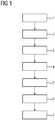
- the schematically illustrated method is used to fix a thin film material on a flat surface of a carrier glass for a microscope device a liquid.
- the procedure includes the following steps. First, a quantity of liquid is applied to the flat surface of the carrier glass (1). Furthermore, the thin film material is applied to the surface of the carrier glass that is partially or completely wetted with liquid (2). Furthermore, a microscopic sample is applied to the surface of the thin film material facing away from the surface of the carrier glass (16) wetted with liquid. The surface of the thin film material (18) facing away from the surface of the carrier glass (16) wetted with liquid is hydrophilic. Furthermore, the sample applied to the surface of the thin film material (18) is microscoped by taking at least one microscopic image of the sample.
- the thin film material (18) with the applied sample is then removed from the carrier glass (16) and the surface of the carrier glass (16) wetted with liquid is cleaned and dried, the drying preferably being carried out with air.
- the carrier glass (16) is then reused in a further run of the method.
- the in FIG 2 Automatic analyzer (11) shown comprises means for automatically executing the in FIG. 1 explained method.
- the means for automatically executing the method comprise a control device which is configured such that it can control an automatic execution of the method.
- the analyzer (11) is designed to analyze blood cells (12) in a sample and comprises an optical microscope (10) comprising a light source (13) for illuminating a sample and a collecting lens for collecting and focusing light beams (14) from the illuminated sample, a camera (15) connected to the microscope (10), an automatic pipettor for pipetting liquids and an automatic transfer arm for transporting the thin film material.
- the sample is a blood sample that contains blood cells (12).
- water is pipetted onto the carrier glass (16) by means of the pipettor, so that a liquid film (17) forms on the carrier glass (16).
- a thin film material (18) in the form of a flexible film is applied to the liquid film (17) by means of the transfer arm.
- the sample with blood cells (12) is applied to the hydrophilic surface (19) of the thin film material (18) by means of the pipettor or another suitable automatic device.
- the hydrophilic surface (19) of the thin film material (18) is on the side of the thin film material (18) which faces away from the liquid film (17).
- the thin film material (18) is fixed on the carrier glass (16) by means of the liquid film (17) made of water.
- the thin film material is thereby aligned parallel to the flat surface of the carrier glass (16).
- the thin film material (18) is lifted off the carrier glass (16) using an automatic device for lifting off the thin film material (18) and the thin film material (18) is removed (5).
- the carrier glass (16) is further cleaned and dried (6) by means of an automatic device for cleaning and drying the carrier glass (18).
- the thin film material (18) and / or the carrier glass (16) is optionally automatically placed in a magazine for storing thin film material (18) or carrier glasses (16).
- an automatic device for marking and / or marking the carrier glasses (16) is used Marking and / or labeling of the carrier glasses (16).
- the marking or marking is preferably a unique marking or marking.
- an automatic device for recognizing and / or recognizing defective carrier glasses (16) detects or recognizes defective carrier glasses (16), which are then automatically sorted out and / or placed in a waste container.
Landscapes
- Physics & Mathematics (AREA)
- Chemical & Material Sciences (AREA)
- Analytical Chemistry (AREA)
- General Physics & Mathematics (AREA)
- General Health & Medical Sciences (AREA)
- Biochemistry (AREA)
- Life Sciences & Earth Sciences (AREA)
- Health & Medical Sciences (AREA)
- Immunology (AREA)
- Pathology (AREA)
- Optics & Photonics (AREA)
- Dispersion Chemistry (AREA)
- Sampling And Sample Adjustment (AREA)
- Sliding-Contact Bearings (AREA)
- Materials For Medical Uses (AREA)
Abstract
Description
- Die Erfindung liegt auf dem Gebiet der automatischen Analyzer und betrifft ein Verfahren für einen Hämatologie-Analyzer zum Analysieren von Zellen in einer Probe unter Verwendung einer Mikroskopiervorrichtung.
- Zur automatisierten Analyse von Zellen werden so genannte "automated cell counters" (Automatisierte Zellzählgeräte) mit zunehmendem Erfolg angewendet. Beispiele hierfür sind die Advia 2120, Sysmex XE-2100 sowie Cobas m 511 Systeme. Diese automatisierten Geräte stellen, abgesehen von ihrer hohen Durchsatzzahl, einige Vorteile bereit, wie beispielsweise hohe Objektivität (keine Variabilität abhängig vom Beobachter), Elimination statistischer Variationen, die üblicherweise mit einer manuellen Zählung verbunden sind (Zählung hoher Zellzahlen), sowie die Bestimmung zahlreicher Parameter, die bei einer manuellen Auszählung nicht verfügbar wären und, wie angesprochen eine effizientere und kosteneffektivere Handhabung. Einige dieser Geräte können 120 bis 150 Patientenproben pro Stunde bearbeiten.
- Die technischen Prinzipien der automatischen Einzelzellzählung wie z.B. in den Advia 2120 und Sysmex XE-2100 Geräten beruhen meist entweder auf einer Impedanz- (Widerstands-) Messung oder auf einem optischen System (Streulicht- bzw. Absorptionsmessung). Weiter sind bildgebende Systeme etabliert, die z.B. Zellen eines Blutausstrichs automatisiert abbilden und bewerten, wie z.B. in den Cobas m 511, CellaVision DM96 und CellaVision 1200 Geräten.
- Beim Impedanzverfahren erfolgt die Zellzählung sowie deren Größenbestimmung auf Grundlage des Nachweises und der Messung von Veränderungen in der elektrischen Leitfähigkeit (Widerstand), die durch ein Teilchen verursacht werden, das sich durch eine kleine Öffnung hindurchbewegt. Teilchen, wie beispielsweise Blutzellen, sind selbst nicht leitend, werden jedoch in einem elektrisch leitenden Verdünnungsmittel suspendiert. Wenn eine derartige Suspension von Zellen durch eine Öffnung hindurchgeleitet wird, nimmt bei Durchgang einer einzelnen individuellen Zelle die Impedanz (Widerstand) des elektrischen Weges zwischen den beiden Elektroden, die sich auf jeder Seite der Öffnung befinden, vorübergehend zu.
- Im Gegensatz zum Impedanzverfahren umfasst das optische Verfahren das Durchleiten eines Laserlichtstrahles oder eines LED Lichtstrahls durch eine verdünnte Blutprobe, die in einem kontinuierlichen Strom von dem Laserstrahl oder dem LED Lichtstrahl erfasst wird. Der entsprechende Lichtstrahl kann dabei z.B. mittels eines Lichtwellenleiters zur Durchflusszelle geleitet werden. Jede Zelle, die durch die Erfassungszone der Durchflusszelle hindurchtritt, streut das fokussierte Licht. Das gestreute Licht wird dann durch einen Fotodetektor nachgewiesen und in einen elektrischen Impuls umgewandelt. Die hier erzeugte Anzahl von Impulsen ist direkt zur Zellanzahl proportional, die durch die Erfassungszone in einer speziellen Zeitspanne hindurchtritt.
- Bei den optischen Verfahren wird die Lichtstreuung der einzelnen Zelle, die durch die Erfassungszone hindurchtritt, in verschiedenen Winkeln gemessen. Hierdurch wird das Streuverhalten der jeweiligen Zelle für die optische Strahlung erfasst, das Rückschlüsse auf z.B. die Zellstruktur, Form und Reflexionsvermögen erlaubt. Dieses Streuverhalten kann dazu verwendet werden, verschiedene Arten von Blutzellen zu differenzieren und die abgeleiteten Parameter zur Diagnose von Abweichungen der Blutzellen dieser Probe von einer Norm, die z.B. aus einer Vielzahl von als normal klassifizierten Referenzproben gewonnen wurde, zu verwenden.
- Für die Anfertigung von Blutausstrichen zur Differenzialdiagnostik wird bisher üblicherweise eine Blutprobe auf einem Glasobjektträger ausgestrichen und manuell oder automatisiert mikroskopisch ausgewertet. Glasobjektträger verursachen hohe Kosten in der Herstellung. Weiter ist Glas sehr zerbrechlich und es kann beim Zerbrechen zur Entstehung scharfer Kanten kommen, was zu einem erhöhten Verletzungsrisiko des Laborpersonals führt. Gerade im Labor sind Schnittverletzungen besonders gefährlich, weil dadurch die natürliche Barriere Schicht der Haut beschädigt wird und ein Eindringen von Pathogenen möglich wird. Dadurch steigt das Risiko einer Infektion mit Krankheitserregern deutlich an.
- Glasobjektträger lassen sich durch Dünnfilmmaterialien wie z.B. Folien als Trägermaterial für die Ausbringung von Blut und dessen Mikroskopie ersetzen. Die Verwendung eines Dünnfilmmaterials wie z.B. einer Folie als Trägermaterial für die Ausbringung von Blut und dessen Mikroskopie bringt jedoch das Problem mit sich, dass Folie im Vergleich zu Glas sehr flexible und biegsam ist und dadurch bedingt keine hohe Planarität aufweist. Für die Mikroskopie ist jedoch eine hohe Planarität erforderlich, um eine gute Aufnahmen der Zellen zu ermöglichen. Insbesondere in der automatisierten Mikroskopie ist eine hohe Planarität auch für die exakte Ausrichtung der Probe wichtig um qualitativ hochwertige Bilder zu erhalten.
- Eine der Erfindung zugrundeliegende Aufgabe ist daher das Bereitstellen einer Vorrichtung und eines Verfahrens, mittels dem eine Planarisierung des Dünnfilmmaterials erreicht werden kann. Da heutige hochauflösende Mikroskope für die automatisierte Bewertung von Zellen in Blutausstrichen mit hoher numerischer Apertur arbeiten und damit mit Immersion zwischen Objektträger und Objektive und gegebenenfalls auch zwischen Objektträger und Kondensor, ist die Einschubdicke eines Folienobjektträgers inklusive einer Vorrichtung zur Planarisierung auf eine Dicke von etwa 1.4 mm begrenzt. Somit steht einer Vorrichtung und einem Verfahren, mittels dem eine Planarisierung des Dünnfilmmaterials erfolgt, nur ein sehr begrenzter Raum hinsichtlich dieser Einschubdicke zur Verfügung.
- Die Aufgabe wird von einem erfindungsgemäßen Verfahren, einer entsprechenden Verwendung eines Verfahrens sowie eines Analyzers gemäß der unabhängigen Patentansprüche gelöst. Vorteilhafte Weiterbildungen der Erfindung sind insbesondere auch durch die Unteransprüche gegeben.
- Die Erfindung geht von der Idee aus, Dünnfilmmaterial mit Hilfe einer geringen Menge Wasser auf einem transparenten Träger mit guten optischen Eigenschaften und einer hohen Planarität temporär zu fixieren. Für die Ausbringung von Blut auf dem Dünnfilmmaterial ist es zudem wichtig, dass die entsprechende Oberfläche, auf die das Blut aufgebracht werden soll, eine hydrophile Oberfläche ist.
- Der Gegenstand der Erfindung umfasst insbesondere ein Verfahren zur Fixierung eines Dünnfilmmaterials auf einer planen Oberfläche eines Trägerglases für eine Mikroskopiervorrichtung mittels einer Flüssigkeit, das Verfahren umfassend die folgenden Schritte. Aufbringen einer Flüssigkeitsmenge auf die plane Oberfläche des Trägerglases, Aufbringen des Dünnfilmmaterials auf die wenigstens teilweise, bevorzugt vollständig mit Flüssigkeit benetzten Oberfläche des Trägerglases, Aufbringen einer mikroskopisch zu untersuchenden Probe auf die der mit Flüssigkeit benetzte Oberfläche des Trägerglases abgewandten Oberfläche des Dünnfilmmaterials, wobei die der mit Flüssigkeit benetzten Oberfläche des Trägerglases abgewandte Oberfläche des Dünnfilmmaterials hydrophil ist.
- Das erfindungsgemäße Verfahren hat den Vorteil, dass eine Planarisierung des Dünnfilmmaterials mit besonders einfachen Mitteln zuverlässig erreicht werden kann. Durch die damit mögliche Verwendung von Dünnfilmmaterial wie z.B. Folie lassen sich die Kosten für die Anfertigung eines Blutausstriches deutlich reduzieren. Ein Folienobjektträger ist in der Herstellung wesentlich günstiger als ein Glasobjektträger. Weiter ist ein Folienobjektträger bis zu 10-fach dünner als Glas. Dadurch ist es möglich eine Kassette mit Objektträgern herzustellen, die bei gleicher Größe, bis zu 10-mal mehr Objektträger beinhaltet, wodurch mehr Objektträger gleichzeitig in ein entsprechendes Gerät geladen werden können. Weiter wird bei der Verwendung von Folienobjektträgern weniger Abfall produziert als bei der Verwendung von Glasobjektträgern. Darüber hinaus ist ein Dünnfilmmaterial wie z.B. eine Folie im Vergleich zu Glas nicht zerbrechlich wodurch das Risiko einer Verletzung durch scharfe Kanten deutlich reduziert wird.
- Bei dem Trägerglas handelt es sich bevorzugt um einen Objektträger, der im Gegensatz zu herkömmlichen Objektträgern aus bruchsichererem Glas besteht. Bevorzugt weist das Trägerglas eine hohe Kantengüte und/oder eine hohe Stabilität auf. Eine hohe Kantengüte kann die Stabilität des Glases erhöhen. Eine hohe Stabilität des Trägerglases ist insbesondere vorteilhaft für die mehrfache Benutzung, beziehungsweise die wiederholte Verwendung in einem automatischen Analyzer.
- Besonders bevorzugt besteht das Trägerglas aus einem Corning Gorilla™ Glas von Corning Incorporated und/oder einem chemisch verstärktem Aluminosilicatglas wie z.B. Xensation™ Cover von SCHOTT Technical Glass Solutions GmbH.
- In einer vorteilhaften Ausgestaltung des erfindungsgemäßen Verfahrens weist das Verfahren weiter den folgenden Schritt auf: Mikroskopie der auf der Oberfläche des Dünnfilmmaterials aufgebrachten Probe. Dies hat den Vorteil, dass ein entsprechendes Bild der mikroskopischen Struktur der Probe erhalten wird.
- In einer vorteilhaften Ausgestaltung des erfindungsgemäßen Verfahrens weist das Verfahren weiter die folgenden Schritte auf: Entfernen des Dünnfilmmaterials mit der aufgebrachten Probe von dem Trägerglas, Reinigung und Trocknung der mit Flüssigkeit benetzten Oberfläche des Trägerglases, Wiederverwendung des Trägerglases. Bevorzugt erfolgt die Reinigung dabei mit Luft. Dies hat den Vorteil, dass das Trägerglas wiederverwendet werden kann. Dies kann zu erheblichen Kostenvorteilen führen und vermeidet darüber hinaus unnötige Umweltverschmutzungen und reduziert den Gesamtenergiebedarf.
- In einer weiteren vorteilhaften Ausgestaltung des erfindungsgemäßen Verfahrens beträgt die Gesamtdicke des Trägerglases mit aufgebrachter Flüssigkeit, Dünnfilmmaterial und Probe weniger als 1,4 mm, wobei die Gesamtdicke des Trägerglases mit aufgebrachter Flüssigkeit und Dünnfilmmaterial ohne Probe besonders bevorzugt 1 mm beträgt. Dies hat den Vorteil, dass eine Verwendung des Verfahrens in einem hochauflösenden Mikroskop für die automatisierte Bewertung von Zellen in Blutausstrichen mit hoher numerischer Apertur und mit Immersion zwischen Objektträger und Objektive und gegebenenfalls auch zwischen Objektträger und Kondensor geeignet ist, da die Gesamtdicke kleiner oder gleich der maximalen möglichen Einschubdicke von 1,4 mm ist.
- In einer weiteren vorteilhaften Ausgestaltung des erfindungsgemäßen Verfahrens ist das Dünnfilmmaterial eine biegsame Folie.
- In einer weiteren vorteilhaften Ausgestaltung des erfindungsgemäßen Verfahrens ist die Flüssigkeit im von der Mikroskopiervorrichtung genutzten Spektralbereich überwiegend transparent oder durchsichtig, besonders bevorzugt transparent oder durchsichtig. Überwiegend transparent oder durchsichtig bedeutet, dass man Dahinterliegendes relativ klar erkennen kann, das Material also für Strahlung des jeweiligen Spektralbereichs, bevorzugt z.B. des sichtbaren Spektrums, weitgehend durchlässig ist.
- In einer weiteren vorteilhaften Ausgestaltung des erfindungsgemäßen Verfahrens weist die Flüssigkeit eine Viskosität auf, die kleiner oder gleich der Viskosität von Wasser ist. Dies hat den Vorteil, dass aufgrund der geringen Viskosität der Flüssigkeit eine gleichmäßige Verteilung des Wassers zwischen dem Dünnfilmmaterial, wie z.B. der Folie, und dem Träger erfolgt. Dadurch wird bei der Folie eine ähnlich hohe Planarität erzeugt wie beim Träger.
- In einer weiteren vorteilhaften Ausgestaltung des erfindungsgemäßen Verfahrens enthält die Flüssigkeit Wasser.
- In einer weiteren vorteilhaften Ausgestaltung des erfindungsgemäßen Verfahrens besteht die Flüssigkeit aus Wasser. Dies hat den Vorteil, dass die Fixierung mit Wasser es ermöglicht auf einfache und kostengünstige Weise Dünnfilmmaterial, wie z.B. Folie, für die Hochdurchsatzmikroskopie zu verwenden. Die Fixierung der Folie mit Wasser bringt weiter den Vorteil mit sich, dass sich die Folie nach der Mikroskopie wieder vom Träger ablösen lässt. Die Zusammensetzung des Wassers ermöglicht eine rückstandsloses ablösen der Folie vom Träger und dadurch eine besonders einfache Wiederverwendung des Trägers. Die mikroskopierte und wieder vom Träger abgelöste Folie wird anschließend entsorgt. Der Träger wird mit z.B. Luft im System gereinigt und kann anschließend wiederverwendet werden. Die geringe Viskosität von Wasser erlaubt dabei eine gleichmäßige Verteilung des Wassers zwischen dem Dünnfilmmaterial und dem Träger. Wasser bildet dabei aufgrund seiner geringen Viskosität einen sehr gleichmäßigen dünnen Film zwischen dem Träger und dem Dünnfilmmaterial und bindet so das Dünnfilmmaterial temporär an den Träger. Dadurch wird bei der Folie eine ähnlich hohe Planarität erzeugt wie beim Träger. Des Weiteren wird durch die Verwendung von Wasser der Einfluss der Fixierung auf die optischen Eigenschaften sehr gering gehalten bzw. es kommt vorteilshafterweise zu keiner Veränderung der optischen Eigenschaften durch die Fixierung. Nach Beendigung des Mikroskopiervorgangs lässt sich das Dünnfilmmaterial wieder vom Träger ablösen. Zur Wiederverwendung des Trägers muss dieser dann vorzugsweise nur noch getrocknet werden und kann anschließend wiederverwendet werden. Die Zusammensetzung des Wassers ermöglicht dabei ein Rückstandsloses ablösen des Dünnfilmmaterials vom Träger.
- In einer weiteren vorteilhaften Ausgestaltung des erfindungsgemäßen Verfahrens beträgt die auf die plane Oberfläche des Trägerglases aufgebrachte Flüssigkeitsmenge 3.7 bis 11 Nano Liter pro mm2, bevorzugt 4.8 bis 9.6 Nano Liter pro mm2, besonders bevorzugt 5.3 Nano Liter pro mm2.
- In einer weiteren vorteilhaften Ausgestaltung des erfindungsgemäßen Verfahrens ist das Trägerglas im sichtbaren Spektralbereich transparent.
- In einer weiteren vorteilhaften Ausgestaltung des erfindungsgemäßen Verfahrens wird das Dünnfilmmaterial mit einem zweiten Dünnfilmmaterial, z.B. einer zweiten Folie, abgedeckt, wobei die Dicke des zweiten Dünnfilmmaterials bzw. der zweiten Folie bevorzugt 0.1 bis 0.17 mm beträgt. Dies hat den Vorteil, dass die zweite Folie als Deckglas dient. In der Hämatologie verwendet man in der Regel keine Deckgläser, es gibt jedoch andere Anwendungen bei denen eine Verwendung von eingedeckelten Proben vorteilhaft ist. Häufig ist es auch aufgrund der technischen Gegebenheiten des verwendeten Mikroskops nicht möglich eine uneingedeckelte Probe zu mikroskopieren.
- In einer weiteren vorteilhaften Ausgestaltung des erfindungsgemäßen Verfahrens umfasst die Probe eine menschliche und/oder tierische Körperflüssigkeit, bevorzugt Blut. Bevorzugt enthält die Probe Blutzellen.
- Ein weiterer Gegenstand der Erfindung ist die Verwendung eines erfindungsgemäßen Verfahrens in einem automatischen Analyzer, wobei der Analyzer bevorzugt eine Vorrichtung zum Abheben des Dünnfilmmaterials, z.B. der Folie, vom Trägerglas umfasst.
- Ein weiterer Gegenstand der Erfindung ist die Verwendung eines erfindungsgemäßen Verfahrens in einem automatischen Analyzer, wobei der Analyzer bevorzugt eine Vorrichtung zum Reinigen und Trocknen der Trägergläser umfasst.
- Ein weiterer Gegenstand der Erfindung ist die Verwendung eines erfindungsgemäßen Verfahrens in einem automatischen Analyzer, wobei der Analyzer bevorzugt ein Magazin zur Lagerung der Trägergläser und/oder des Dünnfilmmaterials umfasst.
- Ein weiterer Gegenstand der Erfindung ist die Verwendung eines erfindungsgemäßen Verfahrens in einem automatischen Analyzer, wobei der Analyzer bevorzugt eine Vorrichtung zur Markierung und/oder Kennzeichnung der Trägergläser umfasst.
- Ein weiterer Gegenstand der Erfindung ist die Verwendung eines erfindungsgemäßen Verfahrens in einem automatischen Analyzer, wobei der Analyzer bevorzugt eine Vorrichtung zur Erkennung und/oder Wiedererkennung defekter Trägergläser umfasst.
- Ein weiterer Gegenstand der Erfindung ist ein automatischer Analyzer umfassend Mittel zur automatischen Ausführung eines erfindungsgemäßen Verfahrens, wobei bevorzugt die Mittel eine Steuereinrichtung umfassen, die so konfiguriert ist, dass sie eine automatische Ausführung eines erfindungsgemäßen Verfahrens steuern kann.
- Bevorzugt handelt es sich bei dem erfindungsgemäßen Analysator um einen automatischen Analysator, besonders bevorzugt um einen teilautomatischen oder vollautomatischen Hämatologie-Analysator. Bevorzugt umfasst das Mikroskop eine oder mehrere Kameras. Bevorzugt umfasst die Kamera ein digitales Aufzeichnungsgerät, das zum Aufnehmen des im Mikroskop abgebildeten Lichtfelds ausgebildet ist. Bevorzugt Umfasst das digitale Aufzeichnungsgerät einen charge-coupled device (CCD) Chip oder mehrere CCD Chips. Besonders bevorzugt basiert das digitale Aufzeichnungsgerät auf einer Complementary Metal-Oxide-Semiconductor (CMOS) Technik und/oder umfasst einen CMOS Chip.
- Die Erfindung basiert auf einem optischen Mikroskop, das beispielweise mit Vorrichtungen für Differential Interferenzkontrast ausgestattet ist. Solche Mikroskope können dabei in Bezug auf die Aufspaltung auf die Anforderungen der Hämatologie angepasst werden. Diese Anpassung erfolgt im Wesentlichen durch eine gezielte Wahl des Strahlversatzes auf dem Strahlweg durch das Messobjekt. Bei dem Messobjekt handelt es sich beispielsweise um eine ausgestrichene Blutprobe.
- Die Erfindung wird anhand der beigefügten Zeichnung noch einmal durch ein konkretes Ausführungsbeispiel näher erläutert. Das gezeigte Beispiel stellt eine bevorzugte Ausführungsform der Erfindung dar. Es zeigt:
- FIG 1
- eine schematische Darstellung des Ablaufs eines Verfahrens zur Fixierung eines Dünnfilmmaterials auf einer planen Oberfläche eines Trägerglases,
- FIG 2
- einen automatischen Analyzer umfassend Mittel zur automatischen Ausführung eines Verfahrens zur Fixierung eines Dünnfilmmaterials auf einer planen Oberfläche eines Trägerglases.
- Das in
FIG 1 schematisch dargestellte Verfahren dient der Fixierung eines Dünnfilmmaterials auf einer planen Oberfläche eines Trägerglases für eine Mikroskopiervorrichtung mittels einer Flüssigkeit. Das Verfahren umfassend die folgenden Schritte. Zunächst wird eine Flüssigkeitsmenge auf die plane Oberfläche des Trägerglases aufgebracht (1). Weiter wird das Dünnfilmmaterial auf die teilweise oder vollständig mit Flüssigkeit benetzte Oberfläche des Trägerglases aufgebracht (2). Weiter wird eine mikroskopisch zu untersuchende Probe auf die der mit Flüssigkeit benetzten Oberfläche des Trägerglases (16) abgewandten Oberfläche des Dünnfilmmaterials aufgebracht. Hierbei ist die der mit Flüssigkeit benetzten Oberfläche des Trägerglases (16) abgewandte Oberfläche des Dünnfilmmaterials (18) hydrophil. Weiter wird die auf der Oberfläche des Dünnfilmmaterials (18) aufgebrachte Probe mikroskopiert durch Aufnahme von mindestens einem mikroskopischen Bild der Probe. Anschließend wird das Dünnfilmmaterial (18) mit der aufgebrachten Probe von dem Trägerglas (16) entfernt und die mit Flüssigkeit benetzte Oberfläche des Trägerglases (16) gereinigt und getrocknet, wobei die Trocknung bevorzugt mit Luft erfolgt. Anschließend wird das Trägerglas (16) wiederverwendet in einem weiteren Durchlauf des Verfahrens. - Der in
FIG 2 gezeigte automatische Analyzer (11) umfasst Mittel zur automatischen Ausführung des inFIG 1 erläuterten Verfahrens. Die Mittel zur automatischen Ausführung des Verfahrens umfassen eine Steuereinrichtung, die so konfiguriert ist, dass sie eine automatische Ausführung des Verfahrens steuern kann. - Der Analyzer (11) ist ausgestaltet zum Analysieren von Blutzellen (12) in einer Probe und umfasst ein optisches Mikroskop (10) umfassend eine Lichtquelle (13) zum Beleuchten einer Probe und eine Sammellinse zum Sammeln und Fokussieren von Lichtstrahlen (14), die von der beleuchteten Probe ausgehen, eine mit dem Mikroskop (10) verbundene Kamera (15), einen automatischen Pipettor zum pipettieren von Flüssigkeiten sowie einen automatischen Transferarm zum transportieren des Dünnfilmmaterials. Bei der Probe handelt es sich um eine Blutprobe, die Blutzellen (12) enthält.
- Zunächst wird auf das Trägerglas (16) mittels des Pipettors Wasser pipettiert, so dass sich ein Flüssigkeitsfilm (17) auf dem Trägerglas (16) ausbildet. Dann wird ein Dünnfilmmaterial (18) in Form einer flexiblen Folie mittels des Transferarms auf den Flüssigkeitsfilm (17) aufgebracht. Weiter wird mittels des Pipettors oder einer anderen geeigneten automatischen Vorrichtung die Probe mit Blutzellen (12) auf die hydrophile Oberfläche (19) des Dünnfilmmaterials (18) aufgebracht. Die hydrophile Oberfläche (19) des Dünnfilmmaterials (18) befindet sich dabei auf der Seite des Dünnfilmmaterials (18), welche dem Flüssigkeitsfilm (17) abgewandt ist.
- Zur mikroskopischen Abbildung der Probe befindet sich diese somit nach Ausführung des Verfahrens auf der hydrophoben Oberfläche (19) des Dünnfilmmaterials (18). Das Dünnfilmmaterial (18) ist mittels des Flüssigkeitsfilms (17) aus Wasser auf dem Trägerglas (16) fixiert. Das Dünnfilmmaterial ist dadurch parallel zur planen Oberfläche des Trägerglases (16) ausgerichtet.
- Nach Durchführung der Mikroskopie der Probe (4) wird mit einer automatischen Vorrichtung zum Abheben des Dünnfilmmaterials (18) das Dünnfilmmaterial (18) vom Trägerglas (16) abgehoben und das Dünnfilmmaterial (18) entfernt (5).
- Weiter wird das Trägerglas (16) mittels einer automatischen Vorrichtung zum Reinigen und Trocknen des Trägerglases (18) gereinigt und getrocknet (6).
- Das Dünnfilmmaterial (18) und/oder das Trägerglas (16) wird optional jeweils in ein Magazin zu Lagerung von Dünnfilmmaterial (18) beziehungsweise von Trägergläsern (16) automatisch verbracht.
- Optional erfolgt mittels einer automatischen Vorrichtung zur Markierung und/oder Kennzeichnung der Trägergläser (16) eine Markierung und/oder Kennzeichnung der Trägergläser (16). Bevorzugt handelt es sich bei der Markierung beziehungsweise Kennzeichnung um eine jeweils eineindeutige Kennzeichnung beziehungsweise Markierung.
- Optional erfolgt mittels einer automatischen Vorrichtung zur Erkennung und/oder Wiedererkennung defekter Trägergläser (16) eine Erkennung beziehungsweise Wiedererkennung von defekten Trägergläsern (16), die dann z.B. automatisch aussortiert und/oder in einen Abfallbehälter verbracht werden.
-
- 1
- Aufbringen Flüssigkeitsmenge
- 2
- Aufbringen Dünnfilmmaterial
- 3
- Aufbringen Probe
- 4
- Mikroskopie Probe
- 5
- Entfernen Dünnfilmmaterial
- 6
- Reinigung und Trocknung
- 7
- Wiederverwendung Trägerglas
- 10
- Mikroskop
- 11
- Analyzer
- 12
- Blutzelle
- 13
- Lichtquelle
- 14
- Lichtstrahlen
- 15
- Kamera
- 16
- Trägerglas
- 17
- Flüssigkeitsfilm
- 18
- Dünnfilmmaterial
- 19
- hydrophile Oberfläche
Claims (16)
- Verfahren zur Fixierung eines Dünnfilmmaterials (17) auf einer planen Oberfläche eines Trägerglases (16) für eine Mikroskopiervorrichtung mittels einer Flüssigkeit, das Verfahren umfassend die folgenden Schritte:- Aufbringen einer Flüssigkeitsmenge auf die plane Oberfläche des Trägerglases (16),- Aufbringen des Dünnfilmmaterials (18) auf die wenigstens teilweise, bevorzugt vollständig mit Flüssigkeit benetzten Oberfläche des Trägerglases (16),- Aufbringen einer mikroskopisch zu untersuchenden Probe auf die der mit Flüssigkeit benetzte Oberfläche des Trägerglases abgewandten Oberfläche des Dünnfilmmaterials (18),wobei die der mit Flüssigkeit benetzten Oberfläche des Trägerglases (16) abgewandte Oberfläche des Dünnfilmmaterials (18) hydrophil ist.
- Verfahren nach Anspruch 1, das Verfahren weiter aufweisend den folgenden Schritt:- Mikroskopie der auf der Oberfläche des Dünnfilmmaterials (18) aufgebrachten Probe.
- Verfahren nach einem der vorhergehenden Ansprüche, das Verfahren weiter aufweisend den folgenden Schritt:- Entfernen des Dünnfilmmaterials (18) mit der aufgebrachten Probe von dem Trägerglas (16),- Reinigung und Trocknung der mit Flüssigkeit benetzten Oberfläche des Trägerglases (16),- Wiederverwendung des Trägerglases (16).
- Verfahren nach einem der vorhergehenden Ansprüche, wobei die Gesamtdicke des Trägerglases (16) mit aufgebrachter Flüssigkeit, Dünnfilmmaterial (18) und Probe weniger als 1,4 mm beträgt, wobei die Gesamtdicke des Trägerglases (16) mit aufgebrachter Flüssigkeit und Dünnfilmmaterial (18) ohne Probe besonders bevorzugt 1 mm beträgt.
- Verfahren nach einem der vorhergehenden Ansprüche, wobei das Dünnfilmmaterial (18) eine biegsame Folie ist.
- Verfahren nach einem der vorhergehenden Ansprüche, wobei die Flüssigkeit im von der Mikroskopiervorrichtung genutzten Spektralbereich überwiegend transparent ist.
- Verfahren nach einem der vorhergehenden Ansprüche, wobei die Flüssigkeit eine Viskosität aufweist, die kleiner oder gleich der Viskosität von Wasser ist.
- Verfahren nach einem der vorhergehenden Ansprüche, wobei die Flüssigkeit Wasser enthält oder aus Wasser besteht.
- Verfahren nach einem der vorhergehenden Ansprüche, wobei die auf die plane Oberfläche des Trägerglases (16) aufgebrachte Flüssigkeitsmenge 3.7 bis 11 Nano Liter pro mm2 beträgt, bevorzugt 4.8 bis 9.6 Nano Liter pro mm2, besonders bevorzugt 5.3 Nano Liter pro mm2.
- Verfahren nach einem der vorhergehenden Ansprüche, wobei das Trägerglas (16) im sichtbaren Spektralbereich transparent ist.
- Verfahren nach einem der vorhergehenden Ansprüche, wobei das Trägerglas (16) aus Glas und/oder Kunststoff besteht.
- Verfahren nach einem der vorhergegangen Ansprüche wobei das Dünnfilmmaterial (18) mit einem zweiten Dünnfilmmaterial abgedeckt wird, wobei die Dicke des zweiten Dünnfilmmaterials bevorzugt 0.1 bis 0.17 mm beträgt.
- Verfahren nach einem der vorhergehenden Ansprüche, wobei die Probe eine menschliche und/oder tierische Körperflüssigkeit, bevorzugt Blut, umfasst.
- Verwendung eines Verfahrens nach einem der Ansprüche 1 bis 13 in einer Mikroskopiervorrichtung.
- Verwendung eines Verfahrens nach einem der Ansprüche 1 bis 13 in einem automatischen Analyzer (11), wobei der Analyzer bevorzugt eine Mikroskopiervorrichtung umfasst.
- Automatischer Analyzer (11) umfassend Mittel zur automatischen Ausführung eines Verfahrens nach einem der Ansprüche 1 bis 13, wobei bevorzugt die Mittel eine Steuereinrichtung umfassen, die so konfiguriert ist, dass sie eine automatische Ausführung eines Verfahrens nach einem der Ansprüche 1 bis 13 steuern kann.
Priority Applications (4)
| Application Number | Priority Date | Filing Date | Title |
|---|---|---|---|
| EP18192845.8A EP3620773B1 (de) | 2018-09-06 | 2018-09-06 | Verfahren zur fixierung eines dünnfilmmaterials auf einem trägerglas |
| ES18192845T ES2940241T3 (es) | 2018-09-06 | 2018-09-06 | Procedimiento para la fijación de un material de lámina fina sobre un vidrio portante |
| US17/274,158 US20210239580A1 (en) | 2018-09-06 | 2019-08-26 | Method for fixing a thin-film material to a slide |
| PCT/IB2019/057142 WO2020049400A1 (de) | 2018-09-06 | 2019-08-26 | Verfahren zur fixierung eines dünnfilmmaterials auf einem trägerglas |
Applications Claiming Priority (1)
| Application Number | Priority Date | Filing Date | Title |
|---|---|---|---|
| EP18192845.8A EP3620773B1 (de) | 2018-09-06 | 2018-09-06 | Verfahren zur fixierung eines dünnfilmmaterials auf einem trägerglas |
Publications (2)
| Publication Number | Publication Date |
|---|---|
| EP3620773A1 true EP3620773A1 (de) | 2020-03-11 |
| EP3620773B1 EP3620773B1 (de) | 2022-12-14 |
Family
ID=63524100
Family Applications (1)
| Application Number | Title | Priority Date | Filing Date |
|---|---|---|---|
| EP18192845.8A Active EP3620773B1 (de) | 2018-09-06 | 2018-09-06 | Verfahren zur fixierung eines dünnfilmmaterials auf einem trägerglas |
Country Status (4)
| Country | Link |
|---|---|
| US (1) | US20210239580A1 (de) |
| EP (1) | EP3620773B1 (de) |
| ES (1) | ES2940241T3 (de) |
| WO (1) | WO2020049400A1 (de) |
Citations (3)
| Publication number | Priority date | Publication date | Assignee | Title |
|---|---|---|---|---|
| US3551023A (en) * | 1969-01-17 | 1970-12-29 | Ibm | Pathology specimen processing method and article |
| US4597982A (en) * | 1982-03-18 | 1986-07-01 | Delameter William D | Method for processing flexible sheets |
| CN201444213U (zh) * | 2009-07-17 | 2010-04-28 | 薛峰 | 一次性载物片 |
Family Cites Families (3)
| Publication number | Priority date | Publication date | Assignee | Title |
|---|---|---|---|---|
| JPS6380216A (ja) * | 1986-09-24 | 1988-04-11 | Bio Meito:Kk | プラスチツク製スライドグラス類 |
| JP4068792B2 (ja) * | 2000-07-12 | 2008-03-26 | 東芝機械株式会社 | 観察用標本の作製方法及び装置 |
| CN108139058B (zh) * | 2015-10-22 | 2021-03-23 | 康宁股份有限公司 | 高透射玻璃 |
-
2018
- 2018-09-06 EP EP18192845.8A patent/EP3620773B1/de active Active
- 2018-09-06 ES ES18192845T patent/ES2940241T3/es active Active
-
2019
- 2019-08-26 US US17/274,158 patent/US20210239580A1/en active Pending
- 2019-08-26 WO PCT/IB2019/057142 patent/WO2020049400A1/de not_active Ceased
Patent Citations (3)
| Publication number | Priority date | Publication date | Assignee | Title |
|---|---|---|---|---|
| US3551023A (en) * | 1969-01-17 | 1970-12-29 | Ibm | Pathology specimen processing method and article |
| US4597982A (en) * | 1982-03-18 | 1986-07-01 | Delameter William D | Method for processing flexible sheets |
| CN201444213U (zh) * | 2009-07-17 | 2010-04-28 | 薛峰 | 一次性载物片 |
Also Published As
| Publication number | Publication date |
|---|---|
| ES2940241T3 (es) | 2023-05-04 |
| EP3620773B1 (de) | 2022-12-14 |
| WO2020049400A1 (de) | 2020-03-12 |
| US20210239580A1 (en) | 2021-08-05 |
Similar Documents
| Publication | Publication Date | Title |
|---|---|---|
| DE10304653B4 (de) | Mehrparametrige Detektion in einem fluidischen Mikrosystem | |
| DE60034743T2 (de) | Verfahren und Vorrichtung zur Abtrennung von festförmigen Bestandteilen aus einem flüssigen Bestandteil in einem biologischen Flüssigkeit | |
| DE10033268C2 (de) | Verfahren zur Untersuchung von Zellen in einer Kulturflüssigkeit | |
| DE69409567T2 (de) | Durchflusszellenvorrichtung | |
| EP3042177B1 (de) | In-vitro-verfahren zum markierungsfreien bestimmen eines zelltyps einer zelle | |
| EP2239557B1 (de) | Verfahren zur Messung luftgetragener biologischer Gefahrstoffe | |
| DE69126839T2 (de) | Automatisches zellenklassifikationssystem und verfahren | |
| EP3017296B1 (de) | Lasermikrodissektionssystem und untersuchungsverfahren für nukleinsäurehaltige proben | |
| EP0177718A2 (de) | Verfahren und Vorrichtung zur Sortierung von mikroskopischen Partikeln | |
| DE1498824A1 (de) | Vorrichtung zur maschinellen Krebsdiagnose | |
| WO2005010591A1 (de) | Vorrichtung und verfahren zur untersuchung chemischer und/ oder biologischer proben sowie objektivaufsatz | |
| DE102017107348A1 (de) | Verfahren zur zytometrischen Analyse von Zellproben | |
| DE69329324T2 (de) | Automatische Detektion von kanzerogenem oder vorkanzerogenem Gewebe durch Messung maligner Veränderungen | |
| WO2014191383A1 (de) | Verfahren zur lasermikrodissektion und lasermikrodissektionssystem | |
| EP3620773B1 (de) | Verfahren zur fixierung eines dünnfilmmaterials auf einem trägerglas | |
| DE19637741B4 (de) | Automatisches Zytologisches Probenanalysesystem unter Verwendung von individualisierten Patientendaten | |
| DE10203300C1 (de) | Verfahren und Anordnung zum Erkennen klebender Partikel an Oberflächen von Papier, Pappe und in Suspensionen | |
| DE10141051A1 (de) | Anordnung und Verfahren zur Inspektion von unstruktuierten Wafern | |
| DE10128552B4 (de) | Verfahren zur Zellanalyse und Zellanalyseeinrichtung | |
| DE102009039869B4 (de) | Gelträger zur Durchführung des COMET-Assays mit Automatisierungsmöglichkeit im Roboter-gestützten Analysebetrieb zur Realisierung eines Hochdurchsatz-Verfahrens | |
| EP3647767B1 (de) | Isovolumetrisches aufkugeln von roten blutzellen | |
| DE112010000856T5 (de) | Automatischer Analysator | |
| EP0530186B1 (de) | Objektträger für nasse oder feuchte präparate, z.b. blut | |
| DE102007046615A1 (de) | Gelträger zur Durchführung des COMET-Assays mit Automatisierungsmöglichkeit im Roboter-gestützten Analysebetrieb zur Realisierung eines Hochdurchsatz-Verfahrens | |
| EP1594613B1 (de) | Verfahren zur untersuchung zellulärer proben |
Legal Events
| Date | Code | Title | Description |
|---|---|---|---|
| PUAI | Public reference made under article 153(3) epc to a published international application that has entered the european phase |
Free format text: ORIGINAL CODE: 0009012 |
|
| STAA | Information on the status of an ep patent application or granted ep patent |
Free format text: STATUS: THE APPLICATION HAS BEEN PUBLISHED |
|
| AK | Designated contracting states |
Kind code of ref document: A1 Designated state(s): AL AT BE BG CH CY CZ DE DK EE ES FI FR GB GR HR HU IE IS IT LI LT LU LV MC MK MT NL NO PL PT RO RS SE SI SK SM TR |
|
| AX | Request for extension of the european patent |
Extension state: BA ME |
|
| STAA | Information on the status of an ep patent application or granted ep patent |
Free format text: STATUS: REQUEST FOR EXAMINATION WAS MADE |
|
| 17P | Request for examination filed |
Effective date: 20200909 |
|
| RBV | Designated contracting states (corrected) |
Designated state(s): AL AT BE BG CH CY CZ DE DK EE ES FI FR GB GR HR HU IE IS IT LI LT LU LV MC MK MT NL NO PL PT RO RS SE SI SK SM TR |
|
| GRAP | Despatch of communication of intention to grant a patent |
Free format text: ORIGINAL CODE: EPIDOSNIGR1 |
|
| STAA | Information on the status of an ep patent application or granted ep patent |
Free format text: STATUS: GRANT OF PATENT IS INTENDED |
|
| GRAJ | Information related to disapproval of communication of intention to grant by the applicant or resumption of examination proceedings by the epo deleted |
Free format text: ORIGINAL CODE: EPIDOSDIGR1 |
|
| INTG | Intention to grant announced |
Effective date: 20220518 |
|
| STAA | Information on the status of an ep patent application or granted ep patent |
Free format text: STATUS: REQUEST FOR EXAMINATION WAS MADE |
|
| GRAP | Despatch of communication of intention to grant a patent |
Free format text: ORIGINAL CODE: EPIDOSNIGR1 |
|
| STAA | Information on the status of an ep patent application or granted ep patent |
Free format text: STATUS: GRANT OF PATENT IS INTENDED |
|
| GRAJ | Information related to disapproval of communication of intention to grant by the applicant or resumption of examination proceedings by the epo deleted |
Free format text: ORIGINAL CODE: EPIDOSDIGR1 |
|
| STAA | Information on the status of an ep patent application or granted ep patent |
Free format text: STATUS: REQUEST FOR EXAMINATION WAS MADE |
|
| INTC | Intention to grant announced (deleted) | ||
| INTG | Intention to grant announced |
Effective date: 20220713 |
|
| INTC | Intention to grant announced (deleted) | ||
| GRAP | Despatch of communication of intention to grant a patent |
Free format text: ORIGINAL CODE: EPIDOSNIGR1 |
|
| STAA | Information on the status of an ep patent application or granted ep patent |
Free format text: STATUS: GRANT OF PATENT IS INTENDED |
|
| INTG | Intention to grant announced |
Effective date: 20220921 |
|
| GRAS | Grant fee paid |
Free format text: ORIGINAL CODE: EPIDOSNIGR3 |
|
| GRAA | (expected) grant |
Free format text: ORIGINAL CODE: 0009210 |
|
| STAA | Information on the status of an ep patent application or granted ep patent |
Free format text: STATUS: THE PATENT HAS BEEN GRANTED |
|
| AK | Designated contracting states |
Kind code of ref document: B1 Designated state(s): AL AT BE BG CH CY CZ DE DK EE ES FI FR GB GR HR HU IE IS IT LI LT LU LV MC MK MT NL NO PL PT RO RS SE SI SK SM TR |
|
| REG | Reference to a national code |
Ref country code: GB Ref legal event code: FG4D Free format text: NOT ENGLISH |
|
| REG | Reference to a national code |
Ref country code: CH Ref legal event code: EP |
|
| REG | Reference to a national code |
Ref country code: DE Ref legal event code: R096 Ref document number: 502018011210 Country of ref document: DE |
|
| REG | Reference to a national code |
Ref country code: IE Ref legal event code: FG4D Free format text: LANGUAGE OF EP DOCUMENT: GERMAN |
|
| REG | Reference to a national code |
Ref country code: AT Ref legal event code: REF Ref document number: 1537957 Country of ref document: AT Kind code of ref document: T Effective date: 20230115 |
|
| REG | Reference to a national code |
Ref country code: SE Ref legal event code: TRGR |
|
| REG | Reference to a national code |
Ref country code: LT Ref legal event code: MG9D |
|
| REG | Reference to a national code |
Ref country code: NL Ref legal event code: MP Effective date: 20221214 |
|
| PG25 | Lapsed in a contracting state [announced via postgrant information from national office to epo] |
Ref country code: NO Free format text: LAPSE BECAUSE OF FAILURE TO SUBMIT A TRANSLATION OF THE DESCRIPTION OR TO PAY THE FEE WITHIN THE PRESCRIBED TIME-LIMIT Effective date: 20230314 Ref country code: LT Free format text: LAPSE BECAUSE OF FAILURE TO SUBMIT A TRANSLATION OF THE DESCRIPTION OR TO PAY THE FEE WITHIN THE PRESCRIBED TIME-LIMIT Effective date: 20221214 Ref country code: FI Free format text: LAPSE BECAUSE OF FAILURE TO SUBMIT A TRANSLATION OF THE DESCRIPTION OR TO PAY THE FEE WITHIN THE PRESCRIBED TIME-LIMIT Effective date: 20221214 |
|
| REG | Reference to a national code |
Ref country code: ES Ref legal event code: FG2A Ref document number: 2940241 Country of ref document: ES Kind code of ref document: T3 Effective date: 20230504 |
|
| PG25 | Lapsed in a contracting state [announced via postgrant information from national office to epo] |
Ref country code: RS Free format text: LAPSE BECAUSE OF FAILURE TO SUBMIT A TRANSLATION OF THE DESCRIPTION OR TO PAY THE FEE WITHIN THE PRESCRIBED TIME-LIMIT Effective date: 20221214 Ref country code: LV Free format text: LAPSE BECAUSE OF FAILURE TO SUBMIT A TRANSLATION OF THE DESCRIPTION OR TO PAY THE FEE WITHIN THE PRESCRIBED TIME-LIMIT Effective date: 20221214 Ref country code: HR Free format text: LAPSE BECAUSE OF FAILURE TO SUBMIT A TRANSLATION OF THE DESCRIPTION OR TO PAY THE FEE WITHIN THE PRESCRIBED TIME-LIMIT Effective date: 20221214 Ref country code: GR Free format text: LAPSE BECAUSE OF FAILURE TO SUBMIT A TRANSLATION OF THE DESCRIPTION OR TO PAY THE FEE WITHIN THE PRESCRIBED TIME-LIMIT Effective date: 20230315 |
|
| PG25 | Lapsed in a contracting state [announced via postgrant information from national office to epo] |
Ref country code: NL Free format text: LAPSE BECAUSE OF FAILURE TO SUBMIT A TRANSLATION OF THE DESCRIPTION OR TO PAY THE FEE WITHIN THE PRESCRIBED TIME-LIMIT Effective date: 20221214 |
|
| PG25 | Lapsed in a contracting state [announced via postgrant information from national office to epo] |
Ref country code: SM Free format text: LAPSE BECAUSE OF FAILURE TO SUBMIT A TRANSLATION OF THE DESCRIPTION OR TO PAY THE FEE WITHIN THE PRESCRIBED TIME-LIMIT Effective date: 20221214 Ref country code: RO Free format text: LAPSE BECAUSE OF FAILURE TO SUBMIT A TRANSLATION OF THE DESCRIPTION OR TO PAY THE FEE WITHIN THE PRESCRIBED TIME-LIMIT Effective date: 20221214 Ref country code: PT Free format text: LAPSE BECAUSE OF FAILURE TO SUBMIT A TRANSLATION OF THE DESCRIPTION OR TO PAY THE FEE WITHIN THE PRESCRIBED TIME-LIMIT Effective date: 20230414 Ref country code: EE Free format text: LAPSE BECAUSE OF FAILURE TO SUBMIT A TRANSLATION OF THE DESCRIPTION OR TO PAY THE FEE WITHIN THE PRESCRIBED TIME-LIMIT Effective date: 20221214 Ref country code: CZ Free format text: LAPSE BECAUSE OF FAILURE TO SUBMIT A TRANSLATION OF THE DESCRIPTION OR TO PAY THE FEE WITHIN THE PRESCRIBED TIME-LIMIT Effective date: 20221214 |
|
| PG25 | Lapsed in a contracting state [announced via postgrant information from national office to epo] |
Ref country code: SK Free format text: LAPSE BECAUSE OF FAILURE TO SUBMIT A TRANSLATION OF THE DESCRIPTION OR TO PAY THE FEE WITHIN THE PRESCRIBED TIME-LIMIT Effective date: 20221214 Ref country code: PL Free format text: LAPSE BECAUSE OF FAILURE TO SUBMIT A TRANSLATION OF THE DESCRIPTION OR TO PAY THE FEE WITHIN THE PRESCRIBED TIME-LIMIT Effective date: 20221214 Ref country code: IS Free format text: LAPSE BECAUSE OF FAILURE TO SUBMIT A TRANSLATION OF THE DESCRIPTION OR TO PAY THE FEE WITHIN THE PRESCRIBED TIME-LIMIT Effective date: 20230414 Ref country code: AL Free format text: LAPSE BECAUSE OF FAILURE TO SUBMIT A TRANSLATION OF THE DESCRIPTION OR TO PAY THE FEE WITHIN THE PRESCRIBED TIME-LIMIT Effective date: 20221214 |
|
| REG | Reference to a national code |
Ref country code: DE Ref legal event code: R097 Ref document number: 502018011210 Country of ref document: DE |
|
| PLBE | No opposition filed within time limit |
Free format text: ORIGINAL CODE: 0009261 |
|
| STAA | Information on the status of an ep patent application or granted ep patent |
Free format text: STATUS: NO OPPOSITION FILED WITHIN TIME LIMIT |
|
| PG25 | Lapsed in a contracting state [announced via postgrant information from national office to epo] |
Ref country code: DK Free format text: LAPSE BECAUSE OF FAILURE TO SUBMIT A TRANSLATION OF THE DESCRIPTION OR TO PAY THE FEE WITHIN THE PRESCRIBED TIME-LIMIT Effective date: 20221214 |
|
| 26N | No opposition filed |
Effective date: 20230915 |
|
| PG25 | Lapsed in a contracting state [announced via postgrant information from national office to epo] |
Ref country code: SI Free format text: LAPSE BECAUSE OF FAILURE TO SUBMIT A TRANSLATION OF THE DESCRIPTION OR TO PAY THE FEE WITHIN THE PRESCRIBED TIME-LIMIT Effective date: 20221214 |
|
| PG25 | Lapsed in a contracting state [announced via postgrant information from national office to epo] |
Ref country code: LU Free format text: LAPSE BECAUSE OF NON-PAYMENT OF DUE FEES Effective date: 20230906 |
|
| REG | Reference to a national code |
Ref country code: BE Ref legal event code: MM Effective date: 20230930 |
|
| PG25 | Lapsed in a contracting state [announced via postgrant information from national office to epo] |
Ref country code: LU Free format text: LAPSE BECAUSE OF NON-PAYMENT OF DUE FEES Effective date: 20230906 Ref country code: MC Free format text: LAPSE BECAUSE OF FAILURE TO SUBMIT A TRANSLATION OF THE DESCRIPTION OR TO PAY THE FEE WITHIN THE PRESCRIBED TIME-LIMIT Effective date: 20221214 |
|
| PG25 | Lapsed in a contracting state [announced via postgrant information from national office to epo] |
Ref country code: BE Free format text: LAPSE BECAUSE OF NON-PAYMENT OF DUE FEES Effective date: 20230930 |
|
| PG25 | Lapsed in a contracting state [announced via postgrant information from national office to epo] |
Ref country code: BG Free format text: LAPSE BECAUSE OF FAILURE TO SUBMIT A TRANSLATION OF THE DESCRIPTION OR TO PAY THE FEE WITHIN THE PRESCRIBED TIME-LIMIT Effective date: 20221214 |
|
| REG | Reference to a national code |
Ref country code: AT Ref legal event code: MM01 Ref document number: 1537957 Country of ref document: AT Kind code of ref document: T Effective date: 20230906 |
|
| PG25 | Lapsed in a contracting state [announced via postgrant information from national office to epo] |
Ref country code: BG Free format text: LAPSE BECAUSE OF FAILURE TO SUBMIT A TRANSLATION OF THE DESCRIPTION OR TO PAY THE FEE WITHIN THE PRESCRIBED TIME-LIMIT Effective date: 20221214 |
|
| PG25 | Lapsed in a contracting state [announced via postgrant information from national office to epo] |
Ref country code: AT Free format text: LAPSE BECAUSE OF NON-PAYMENT OF DUE FEES Effective date: 20230906 |
|
| PG25 | Lapsed in a contracting state [announced via postgrant information from national office to epo] |
Ref country code: AT Free format text: LAPSE BECAUSE OF NON-PAYMENT OF DUE FEES Effective date: 20230906 |
|
| PG25 | Lapsed in a contracting state [announced via postgrant information from national office to epo] |
Ref country code: CY Free format text: LAPSE BECAUSE OF FAILURE TO SUBMIT A TRANSLATION OF THE DESCRIPTION OR TO PAY THE FEE WITHIN THE PRESCRIBED TIME-LIMIT; INVALID AB INITIO Effective date: 20180906 |
|
| REG | Reference to a national code |
Ref country code: DE Ref legal event code: R082 Ref document number: 502018011210 Country of ref document: DE |
|
| PG25 | Lapsed in a contracting state [announced via postgrant information from national office to epo] |
Ref country code: HU Free format text: LAPSE BECAUSE OF FAILURE TO SUBMIT A TRANSLATION OF THE DESCRIPTION OR TO PAY THE FEE WITHIN THE PRESCRIBED TIME-LIMIT; INVALID AB INITIO Effective date: 20180906 |
|
| PGFP | Annual fee paid to national office [announced via postgrant information from national office to epo] |
Ref country code: IT Payment date: 20250924 Year of fee payment: 8 |
|
| PGFP | Annual fee paid to national office [announced via postgrant information from national office to epo] |
Ref country code: FR Payment date: 20250915 Year of fee payment: 8 |
|
| PGFP | Annual fee paid to national office [announced via postgrant information from national office to epo] |
Ref country code: SE Payment date: 20250904 Year of fee payment: 8 |
|
| PGFP | Annual fee paid to national office [announced via postgrant information from national office to epo] |
Ref country code: IE Payment date: 20250918 Year of fee payment: 8 |
|
| REG | Reference to a national code |
Ref country code: CH Ref legal event code: U11 Free format text: ST27 STATUS EVENT CODE: U-0-0-U10-U11 (AS PROVIDED BY THE NATIONAL OFFICE) Effective date: 20251210 |
|
| PG25 | Lapsed in a contracting state [announced via postgrant information from national office to epo] |
Ref country code: TR Free format text: LAPSE BECAUSE OF FAILURE TO SUBMIT A TRANSLATION OF THE DESCRIPTION OR TO PAY THE FEE WITHIN THE PRESCRIBED TIME-LIMIT Effective date: 20221214 |
|
| PGFP | Annual fee paid to national office [announced via postgrant information from national office to epo] |
Ref country code: DE Payment date: 20251120 Year of fee payment: 8 |
|
| PGFP | Annual fee paid to national office [announced via postgrant information from national office to epo] |
Ref country code: GB Payment date: 20251002 Year of fee payment: 8 |
|
| PGFP | Annual fee paid to national office [announced via postgrant information from national office to epo] |
Ref country code: CH Payment date: 20251210 Year of fee payment: 8 |
|
| PGFP | Annual fee paid to national office [announced via postgrant information from national office to epo] |
Ref country code: ES Payment date: 20251219 Year of fee payment: 8 |