EP3620045B1 - Sicherheitsgitter für laubsauger - Google Patents
Sicherheitsgitter für laubsauger Download PDFInfo
- Publication number
- EP3620045B1 EP3620045B1 EP19195435.3A EP19195435A EP3620045B1 EP 3620045 B1 EP3620045 B1 EP 3620045B1 EP 19195435 A EP19195435 A EP 19195435A EP 3620045 B1 EP3620045 B1 EP 3620045B1
- Authority
- EP
- European Patent Office
- Prior art keywords
- cover
- volute
- grill
- blowervac
- actuator
- Prior art date
- Legal status (The legal status is an assumption and is not a legal conclusion. Google has not performed a legal analysis and makes no representation as to the accuracy of the status listed.)
- Active
Links
Images





Classifications
-
- A—HUMAN NECESSITIES
- A47—FURNITURE; DOMESTIC ARTICLES OR APPLIANCES; COFFEE MILLS; SPICE MILLS; SUCTION CLEANERS IN GENERAL
- A47L—DOMESTIC WASHING OR CLEANING; SUCTION CLEANERS IN GENERAL
- A47L9/00—Details or accessories of suction cleaners, e.g. mechanical means for controlling the suction or for effecting pulsating action; Storing devices specially adapted to suction cleaners or parts thereof; Carrying-vehicles specially adapted for suction cleaners
- A47L9/28—Installation of the electric equipment, e.g. adaptation or attachment to the suction cleaner; Controlling suction cleaners by electric means
- A47L9/2889—Safety or protection devices or systems, e.g. for prevention of motor over-heating or for protection of the user
-
- A—HUMAN NECESSITIES
- A01—AGRICULTURE; FORESTRY; ANIMAL HUSBANDRY; HUNTING; TRAPPING; FISHING
- A01G—HORTICULTURE; CULTIVATION OF VEGETABLES, FLOWERS, RICE, FRUIT, VINES, HOPS OR SEAWEED; FORESTRY; WATERING
- A01G20/00—Cultivation of turf, lawn or the like; Apparatus or methods therefor
- A01G20/40—Apparatus for cleaning the lawn or grass surface
- A01G20/43—Apparatus for cleaning the lawn or grass surface for sweeping, collecting or disintegrating lawn debris
- A01G20/47—Vacuum or blower devices
-
- A—HUMAN NECESSITIES
- A47—FURNITURE; DOMESTIC ARTICLES OR APPLIANCES; COFFEE MILLS; SPICE MILLS; SUCTION CLEANERS IN GENERAL
- A47L—DOMESTIC WASHING OR CLEANING; SUCTION CLEANERS IN GENERAL
- A47L5/00—Structural features of suction cleaners
- A47L5/12—Structural features of suction cleaners with power-driven air-pumps or air-compressors, e.g. driven by motor vehicle engine vacuum
- A47L5/14—Structural features of suction cleaners with power-driven air-pumps or air-compressors, e.g. driven by motor vehicle engine vacuum cleaning by blowing-off, also combined with suction cleaning
-
- A—HUMAN NECESSITIES
- A47—FURNITURE; DOMESTIC ARTICLES OR APPLIANCES; COFFEE MILLS; SPICE MILLS; SUCTION CLEANERS IN GENERAL
- A47L—DOMESTIC WASHING OR CLEANING; SUCTION CLEANERS IN GENERAL
- A47L9/00—Details or accessories of suction cleaners, e.g. mechanical means for controlling the suction or for effecting pulsating action; Storing devices specially adapted to suction cleaners or parts thereof; Carrying-vehicles specially adapted for suction cleaners
- A47L9/10—Filters; Dust separators; Dust removal; Automatic exchange of filters
Definitions
- This application is directed to a locking mechanism for a grill for a blower-vacuum type outdoor device to prevent inadvertent exposure of the fan assembly.
- blowervacs Combination blower-vacuum devices, commonly referred to as blowervacs are well known in the art. These devices have a blow mode where air is blown out of an outlet tube to blow leaves, grass clippings and other yard debris to clear patios, sidewalks and other areas. The devices also have a vacuum mode where they suck in leaves and other yard debris through a vacuum tube for disposal into a collection bag.
- a grill When in the blow mode, a grill typically covers the air intake and blocks access to the fan. The grill allows the passage of air, but prevents the user's hand from accidently contacting the fan.
- the grill When converting from the blow mode to the vacuum mode, the grill is typically removed and a vacuum tube is placed over the fan assembly and a collection bag is attached in place of the outlet tube.
- a blower-vacuum device is disclosed in EP 2 628 382 A1 . Therefore, in either the blow mode or vacuum mode, the fan is covered by the grill or the vacuum tube, respectively, and it would be advantageous to ensure that the grill or vacuum tube remain locked in place.
- the present invention is directed to a blowervac device having a housing with a volute that encloses a fan.
- a motor is operatively connected to the fan, so that in a blow mode air is drawn through an air inlet into the volute and blown out through an outlet tube.
- a grill covers the air inlet and is movable between an open and closed position, so that only when the grill is in the closed and locked position, can the motor be actuated. This guards against exposing the fan while it is spinning.
- the blowervac can be converted to operate in a vacuum mode, where the device sucks in leaves or other yard debris into a collection bag.
- the conversion requires the grill to be removed and a vacuum tube placed over the air inlet. Similar to the blow mode, the motor can only be actuated when the vacuum tube is placed over the inlet and locked into position.
- the blowervac has a safety switch that only allows the motor to be actuated when the safety switch is engaged. In both the blow and vacuum modes, the safety switch is engaged only when the grill or vacuum tube is closed and rotated into its locked position.
- the grill includes an outer ring with an inner cover that is rotatable within the outer ring.
- the cover When the grill is initially closed over the air inlet, the cover is in a first position that covers the air inlet, but does not engage the safety switch. Only when the cover is rotated into a second locked position, does it engage the safety switch and allow the motor to be actuated.
- This two-step process eg. the first step of closing the grill and the second step of rotating the cover, decreases the likelihood of inadvertent exposure of the fan.
- the volute has a skirt with slot, which may be L-shaped, and the cover has a pin that corresponds with the slot. Upon closing the grill over the volute, the pin enters the slot and then the cover can be rotated into the locked position.
- the slot provides a secure arrangement for rotation of the cover.
- the cover has a boss that slides into and out of engagement with a safety switch actuator. When the grill is closed over the volute, the boss does not engage the actuator. Only when the cover is rotated does the boss engage the actuator and activate the safety switch.
- the blower vac may comprise an actuator for the safety switch that detects the rotation of the cover.
- the actuator may pivot within the housing in response to the rotation of the cover.
- the cover may have a boss that in a first position does not engage the actuator, and in a second position engages the actuator, wherein the second position is rotationally different than the first position.
- a method of turning on an outdoor garden device comprising the steps of: providing a housing having a motor, a fan driven by the motor, a volute connected to the housing and enclosing a fan, the volute having an air inlet and an air outlet; moving a grill to cover the air inlet to the volute, the grill having an outer ring and a cover rotatable within the ring; and rotating the cover relative to the ring, the cover activating a safety switch allowing for the actuation of the motor.
- the volute may have a skirt with a slot therein, the cover may have a pin that enters the slot when the grill is closed over the air inlet to the volute.
- the cover may have a boss that in a first position does not engage the actuator, and in a second position engages the actuator, wherein the second position is rotationally different than the first position.
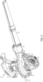
- Figs. 1 and 2 show a blowervac device of the present invention having a main housing 10, which includes a handle 12, a motor housing portion 14 and a foot portion 56.
- a volute 16 is secured to a lower portion of the housing 10 and encloses a fan 24 (shown in Fig. 2 ).
- a grill 18 is secured over a volute opening 22 to cover the fan 24, with Fig. 1 showing the grill 18 in a closed position and Fig. 2 showing the grill 18 in an open position.
- the grill 18 is pivotally secured to the volute by two ears 28 via a boss or pin 30.
- the pin can be a separate piece or can be integrally formed on either the grill or volute with corresponding recesses in the other piece.
- an electrical cord 26 that provides power to a motor for rotating the fan 24.
- the motor can be powered by a removable rechargeable battery for increased portability.
- Fig. 1 shows the blowervac operating in a blow mode with an air outlet tube 32 removably connected to a free end 20 of the volute 16.
- air is drawn into the volute 16 through the grill 18 by the fan 24, and is blown out through the outlet tube 32.
- a vacuum mode as shown in Fig. 3 , the grill 18 is rotated away from volute opening 22 and a vacuum tube 34 is attached.
- the outlet tube 32 is replaced with a collection bag 36 so that any leaves, yard waste or other debris vacuumed up is blown into the collection bag 36.
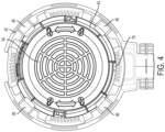
- Fig. 4 shows a bottom view of the grill 18, which includes an outer support ring 42 and an inner cover 44 that is rotatable within the ring 42.
- the inner cover 44 is shown with a thicker line weight to help distinguish it from the outer ring.
- the cover 44 includes concentric air vents 54 to allow airflow to pass through.
- the outer ring 42 includes four arms 46 around its circumference that secure the cover 44 in place.
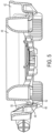
- Fig. 5 is a sectional view showing one of the arms 46.
- the arm 46 is a flexible member that includes an angled cam surface 48.
- the cover 44 is secured to the ring 42 by pushing the cover 44 up from the bottom against the cam surface 48, which biases the arms 46 outwardly. As a tongue 52 passes the cam surface 48, it becomes secured in a groove in the ring 42 between the arm 46 and a rib 50, securing the cover 44 within the ring 42.
- the grill 18 is pivotably secured to the volute 16 at the ears 28, and pivots into and out of engagement with a foot portion 56 of the housing 10.
- the foot portion 56 encloses a movable latch 38 that extends out of the foot portion 56 via a spring 57.
- An end 39 of the latch 38 is angled so that as the grill 18 is closed, a protrusion 45 on the cover 44 slides past the latch 38 and secures the latch between the protrusion 45 and a lip 40 on the cover.
- the latch 38 is pulled inwardly into the foot portion 56, allowing it to be pivoted away from the volute.
- the safety switch 60 must be actuated before power can be delivered to the motor.
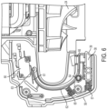
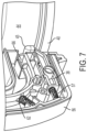
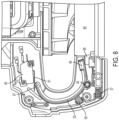
- the safety switch 60 is located in the main housing and is selectively engageable with a generally C-shaped actuator 62 that rotates about a pivot point 64.
- the switch 60 includes a lever 61 that contacts a button 63 for turning the switch 60 "on” and “off'.
- a spring 65 urges the actuator 62 into the default "off' position shown in Fig. 6 .
- a boss member 68 on the cover 44 rotates into engagement with a free end 66 of the actuator 62.
- the actuator 62 pivots about its pivot point 64 against the bias of the spring 65 and the other free end 67 presses the lever 61 against the button 63 to turn "on” the safety switch 60.
- the motor of the blowervac can be actuated.
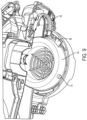
- Fig. 9 shows another view of the boss 68 prior to engagement with the actuator 62.
- Fig. 9 further shows the cover 44 having a pin 70 that helps to secure the grill 18 to the volute 16.
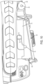
- Fig. 10 when the grill 18 is closed, the pin 70 enters an L-shaped slot 72 in a skirt portion 74 of the volute 16.
- Fig. 11 shows the pin 70 upon initial entrance into the slot 72, after which the cover 44 is rotated relative to the support ring 42, and the pin 70 slides to the end of the slot 72 and is secured the volute 16.
- the slot 72 includes a small bump 73 that the pin 70 rides over and helps to keep in the pin 70 in place.
- the turning of the cover 44 also rotates the boss 68 into engagement with the actuator 62 to activate the switch 60. Therefore, powering the motor and actuating the tool requires the user to take two distinct steps. First the user must close the grill 18 over the volute 16, and then the user must rotate the cover 44 to actuate the switch 60. This two-step process reduces the likelihood of accidental actuation of the tool and reduces the chances of injury to the user.
- Figs. 13 and 14 show that the outer ring 42 includes a rib 76 that confines the rotational extent of the cover 44 (the rib can also be seen in Fig. 4 ).
- the cover 44 has a cut-out 78 within which the rib 76 resides, and in this way, the cover 44 can only be rotated within the limited spaced defined by the cut-out 78.
- the distance between the ends of the cut-out 78 correspond to the length of the slot 72 so that the cover position shown in Fig. 14 corresponds with the pin 70 lining up with the opening in the slot 72 as shown in Fig. 10 , and the cover position shown in Fig. 13 corresponds with the locked pin position shown in Fig. 12 .
- the rib 76 and cut-out 78 prevent over-rotation of the cover 44 and reduces the likelihood of damage to the tool. Furthermore, this assists in locating the pin 70 in its proper position to help close and open the grill.
- the grill 18 is pivoted open to expose the fan 24.
- the vacuum tube 34 is attached to the volute 16 and rotated with respect to the volute in the same way that the cover 44 is attached and rotated to actuate the safety switch 60.
- the vacuum tube includes a pin 80 (similar to the pin 70 on the cover 44) that is secured within the slot 72 of the volute 16.
- the vacuum tube also includes a boss 88 (similar to boss 68 on the cover 44) that engages with the free end 66 of the actuator 62.
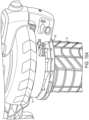
- Figs. 15 and 15A show the vacuum tube 34 in an "off" position so that the boss 88 is not engaged with the actuator 62.
- Fig. 16 shows the vacuum tube rotated relative to Fig. 15 so that the boss engages the actuator 62. In this way, the vacuum mode, like the blow mode, requires two steps to engage the safety switch 60.
Landscapes
- Engineering & Computer Science (AREA)
- Mechanical Engineering (AREA)
- Life Sciences & Earth Sciences (AREA)
- Environmental Sciences (AREA)
- Structures Of Non-Positive Displacement Pumps (AREA)
Claims (10)
- Bläser/Sauger-Vorrichtung, umfassend:ein Gehäuse (10), das einen Motor aufweist;einen vom Motor angetriebenen Lüfter (24);eine Spirale (16), die mit dem Gehäuse verbunden ist und den Lüfter umschließt, wobei die Spirale einen Lufteinlass (22) und einen Luftauslass aufweist;ein Gitter (18), das in der Lage ist, den Lufteinlass zu der Spirale in einem Blasmodus abzudecken, dadurch gekennzeichnet, dass das Gitter einen Außenring (42) und eine innerhalb des Außenrings drehbare Abdeckung (44) aufweist; undeinen Sicherheitsschalter (60), der durch die Drehung der Abdeckung aktiviert wird, wobei der Sicherheitsschalter die Betätigung des Motors verhindert, wenn er sich in der nicht betätigten Position befindet.
- Bläser/Sauger-Vorrichtung nach Anspruch 1, wobei die Spirale eine Schürze (74) mit einem Schlitz (72) darin aufweist, wobei die Abdeckung einen Stift (70) aufweist, der in den Schlitz eintritt, wenn das Gitter über dem Lufteinlass zur Spirale geschlossen ist.
- Bläser/Sauger-Vorrichtung nach Anspruch 2, wobei der Schlitz L-förmig ist.
- Bläser/Sauger-Vorrichtung nach einem vorstehenden Anspruch, die weiter eine Betätigungsvorrichtung (62) für den Sicherheitsschalter beinhaltet, welche die Drehung der Abdeckung erkennt.
- Bläser/Sauger-Vorrichtung nach Anspruch 4, wobei die Betätigungsvorrichtung als Reaktion auf die Drehung der Abdeckung innerhalb des Gehäuses schwenkt.
- Bläser/Sauger-Vorrichtung nach Anspruch 4 oder 5, wobei die Abdeckung einen Vorsprung (68) aufweist, der in einer ersten Position nicht in die Betätigungsvorrichtung eingreift und in einer zweiten Position in die Betätigungsvorrichtung eingreift, wobei sich die zweite Position von der ersten Position hinsichtlich der Drehung unterscheidet.
- Bläser/Sauger-Vorrichtung nach einem vorstehenden Anspruch, die einen Vakuummodus beinhaltet, bei dem ein Vakuumrohr (34) am Lufteinlass der Spirale angebracht ist, wobei das Vakuumrohr eine erste drehbare Position aufweist, in der ein Vorsprung (88) des Vakuumrohrs den Sicherheitsschalter nicht betätigt, und eine zweite drehbare Position, die den Sicherheitsschalter betätigt.
- Verfahren zum Einschalten einer Gartenvorrichtung für den Außenbereich, das die folgenden Schritte umfasst:Bereitstellen eines Gehäuses (10), das einen Motor, einen vom Motor angetriebenen Lüfter (24) und eine mit dem Gehäuse verbundene und einen Lüfter umschließende Spirale (16) aufweist, wobei die Spirale einen Lufteinlass (22) und einen Luftauslass aufweist;Bewegen eines Gitters (18) zum Abdecken des Lufteinlasses zur Spirale, dadurch gekennzeichnet, dass das Gitter einen Außenring (42) und eine innerhalb des Rings drehbare Abdeckung (44) aufweist; undDrehen der Abdeckung relativ zum Ring, wobei die Abdeckung einen Sicherheitsschalter (60) aktiviert, der die Betätigung des Motors ermöglicht.
- Verfahren zum Einschalten einer Gartenvorrichtung für den Außenbereich nach Anspruch 8, wobei die Spirale eine Schürze (74) mit einem Schlitz darin aufweist, wobei die Abdeckung einen Stift (70) aufweist, der in den Schlitz eintritt, wenn das Gitter über dem Lufteinlass zur Spirale geschlossen ist.
- Verfahren zum Einschalten einer Gartenvorrichtung für den Außenbereich nach Anspruch 8 oder 9, wobei die Abdeckung einen Vorsprung (68) aufweist, der in einer ersten Position nicht in die Betätigungsvorrichtung eingreift und in einer zweiten Position in die Betätigungsvorrichtung eingreift, wobei sich die zweite Position von der ersten Position hinsichtlich der Drehung unterscheidet.
Applications Claiming Priority (1)
| Application Number | Priority Date | Filing Date | Title |
|---|---|---|---|
| US16/124,339 US11571101B2 (en) | 2018-09-07 | 2018-09-07 | Blowervac safety grill |
Publications (2)
| Publication Number | Publication Date |
|---|---|
| EP3620045A1 EP3620045A1 (de) | 2020-03-11 |
| EP3620045B1 true EP3620045B1 (de) | 2024-03-27 |
Family
ID=67851068
Family Applications (1)
| Application Number | Title | Priority Date | Filing Date |
|---|---|---|---|
| EP19195435.3A Active EP3620045B1 (de) | 2018-09-07 | 2019-09-04 | Sicherheitsgitter für laubsauger |
Country Status (2)
| Country | Link |
|---|---|
| US (1) | US11571101B2 (de) |
| EP (1) | EP3620045B1 (de) |
Families Citing this family (6)
| Publication number | Priority date | Publication date | Assignee | Title |
|---|---|---|---|---|
| EP3874938B1 (de) * | 2020-03-05 | 2025-08-06 | Andreas Stihl AG & Co. KG | Handgeführtes bearbeitungssystem, handgeführtes bearbeitungsgerät für ein handgeführtes bearbeitungssystem und anbauteil für ein handgeführtes bearbeitungssystem |
| EP3878271A1 (de) * | 2020-03-14 | 2021-09-15 | Ningbo Ruilin Machinery Technology Co., Ltd. | Blas-saug-maschine |
| CN111520345B (zh) * | 2020-04-14 | 2025-09-09 | 浙江动一新能源动力科技股份有限公司 | 一种吹吸风机 |
| USD1025517S1 (en) * | 2021-09-02 | 2024-04-30 | Lei Wan | Cordless leaf blower |
| USD1066833S1 (en) * | 2022-06-15 | 2025-03-11 | Husqvarna Ab | Leaf blower |
| USD1066834S1 (en) * | 2022-06-15 | 2025-03-11 | Husqvarna Ab | Leaf blower |
Family Cites Families (13)
| Publication number | Priority date | Publication date | Assignee | Title |
|---|---|---|---|---|
| US4694528A (en) * | 1986-07-18 | 1987-09-22 | The Toro Company | Convertible vacuum-blower |
| US4870714A (en) | 1987-11-09 | 1989-10-03 | Black & Decker Inc. | Portable blower/vacuum system |
| JP3128181B2 (ja) * | 1994-07-04 | 2001-01-29 | 株式会社共立 | バキュームクリーナ |
| US5535479A (en) | 1995-01-19 | 1996-07-16 | The Toro Company | Portable blower/vacuum handle arrangement |
| EP0723759B1 (de) | 1995-01-30 | 2002-07-10 | Black & Decker Inc. | Blas-/Saugvorrichtung |
| US5560078A (en) | 1995-05-04 | 1996-10-01 | The Toro Company | Portable Blower/Vac |
| US6059541A (en) * | 1998-03-10 | 2000-05-09 | The Toro Company | Air inlet cover for portable blower/vacuum |
| US6442790B1 (en) | 2001-02-09 | 2002-09-03 | The Toro Company | Portable blower/vacuum having air inlet cover attachable to blower tube |
| US6640384B2 (en) | 2001-10-10 | 2003-11-04 | Electrolux Home Products, Inc. | Convertible blower and vacuum |
| US20100086412A1 (en) | 2006-10-13 | 2010-04-08 | Shindaiwa Corporation | Blower |
| CN101205928B (zh) | 2006-12-05 | 2012-06-13 | 安德烈亚斯·斯蒂尔两合公司 | 手持式鼓风机 |
| US7735188B2 (en) | 2006-12-22 | 2010-06-15 | The Toro Company | Air inlet cover and portable blower/vacuum incorporating same |
| ES2559620T3 (es) * | 2012-02-20 | 2016-02-15 | Black & Decker Inc. | Un dispositivo aspirador |
-
2018
- 2018-09-07 US US16/124,339 patent/US11571101B2/en active Active
-
2019
- 2019-09-04 EP EP19195435.3A patent/EP3620045B1/de active Active
Also Published As
| Publication number | Publication date |
|---|---|
| EP3620045A1 (de) | 2020-03-11 |
| US11571101B2 (en) | 2023-02-07 |
| US20200077857A1 (en) | 2020-03-12 |
Similar Documents
| Publication | Publication Date | Title |
|---|---|---|
| US11571101B2 (en) | Blowervac safety grill | |
| AU2013200717B2 (en) | Vacuum and/or blower device | |
| EP2095907B1 (de) | Elektrowerkzeug | |
| US7748078B2 (en) | Blower-vacuum device | |
| JP6660111B2 (ja) | 芝刈機 | |
| US11072052B2 (en) | Guard assembly for a power tool | |
| EP2204082A1 (de) | Elektrischer Mäher mit einem Aktivierungssystem mit zwei Betätigungen | |
| TW200529739A (en) | Power working machine | |
| EP2624738B1 (de) | Tragbare blasvorrichtung mit saugfunktion | |
| US3982082A (en) | Starting system | |
| EP1364571A2 (de) | Kombination Faden- und Messerschneider mit Gebläse-Hilfsfunktion | |
| US6926090B2 (en) | Hinged edger housing having improved internal debris guard and labyrinth perimeter seal | |
| EP2792231B1 (de) | Fangsack mit Drehvorrichtung für einen Laubbläser | |
| JP2004008295A (ja) | 電気掃除機 | |
| CN110651594A (zh) | 割草机 | |
| JP5858233B2 (ja) | 芝刈機 | |
| TWI609667B (zh) | 電動吸塵器 | |
| CN111520345A (zh) | 一种吹吸风机 | |
| JP4969665B2 (ja) | 電気掃除機の吸込具及びその吸込具を備えた電気掃除機 | |
| CN204715267U (zh) | 吹吸机 | |
| CN108240345B (zh) | 电动工具 | |
| JP4654158B2 (ja) | 電気掃除機 | |
| AU2008201539B2 (en) | Housing assembly and latch structure therefor | |
| GB2220104A (en) | Switchbox |
Legal Events
| Date | Code | Title | Description |
|---|---|---|---|
| PUAI | Public reference made under article 153(3) epc to a published international application that has entered the european phase |
Free format text: ORIGINAL CODE: 0009012 |
|
| STAA | Information on the status of an ep patent application or granted ep patent |
Free format text: STATUS: THE APPLICATION HAS BEEN PUBLISHED |
|
| AK | Designated contracting states |
Kind code of ref document: A1 Designated state(s): AL AT BE BG CH CY CZ DE DK EE ES FI FR GB GR HR HU IE IS IT LI LT LU LV MC MK MT NL NO PL PT RO RS SE SI SK SM TR |
|
| AX | Request for extension of the european patent |
Extension state: BA ME |
|
| STAA | Information on the status of an ep patent application or granted ep patent |
Free format text: STATUS: REQUEST FOR EXAMINATION WAS MADE |
|
| 17P | Request for examination filed |
Effective date: 20200904 |
|
| RBV | Designated contracting states (corrected) |
Designated state(s): AL AT BE BG CH CY CZ DE DK EE ES FI FR GB GR HR HU IE IS IT LI LT LU LV MC MK MT NL NO PL PT RO RS SE SI SK SM TR |
|
| STAA | Information on the status of an ep patent application or granted ep patent |
Free format text: STATUS: EXAMINATION IS IN PROGRESS |
|
| 17Q | First examination report despatched |
Effective date: 20221222 |
|
| GRAP | Despatch of communication of intention to grant a patent |
Free format text: ORIGINAL CODE: EPIDOSNIGR1 |
|
| STAA | Information on the status of an ep patent application or granted ep patent |
Free format text: STATUS: GRANT OF PATENT IS INTENDED |
|
| INTG | Intention to grant announced |
Effective date: 20231115 |
|
| GRAS | Grant fee paid |
Free format text: ORIGINAL CODE: EPIDOSNIGR3 |
|
| GRAA | (expected) grant |
Free format text: ORIGINAL CODE: 0009210 |
|
| STAA | Information on the status of an ep patent application or granted ep patent |
Free format text: STATUS: THE PATENT HAS BEEN GRANTED |
|
| AK | Designated contracting states |
Kind code of ref document: B1 Designated state(s): AL AT BE BG CH CY CZ DE DK EE ES FI FR GB GR HR HU IE IS IT LI LT LU LV MC MK MT NL NO PL PT RO RS SE SI SK SM TR |
|
| REG | Reference to a national code |
Ref country code: GB Ref legal event code: FG4D |
|
| REG | Reference to a national code |
Ref country code: CH Ref legal event code: EP |
|
| REG | Reference to a national code |
Ref country code: DE Ref legal event code: R096 Ref document number: 602019048915 Country of ref document: DE |
|
| REG | Reference to a national code |
Ref country code: IE Ref legal event code: FG4D |
|
| PG25 | Lapsed in a contracting state [announced via postgrant information from national office to epo] |
Ref country code: LT Free format text: LAPSE BECAUSE OF FAILURE TO SUBMIT A TRANSLATION OF THE DESCRIPTION OR TO PAY THE FEE WITHIN THE PRESCRIBED TIME-LIMIT Effective date: 20240327 |
|
| REG | Reference to a national code |
Ref country code: LT Ref legal event code: MG9D |
|
| PG25 | Lapsed in a contracting state [announced via postgrant information from national office to epo] |
Ref country code: GR Free format text: LAPSE BECAUSE OF FAILURE TO SUBMIT A TRANSLATION OF THE DESCRIPTION OR TO PAY THE FEE WITHIN THE PRESCRIBED TIME-LIMIT Effective date: 20240628 |
|
| PG25 | Lapsed in a contracting state [announced via postgrant information from national office to epo] |
Ref country code: HR Free format text: LAPSE BECAUSE OF FAILURE TO SUBMIT A TRANSLATION OF THE DESCRIPTION OR TO PAY THE FEE WITHIN THE PRESCRIBED TIME-LIMIT Effective date: 20240327 Ref country code: RS Free format text: LAPSE BECAUSE OF FAILURE TO SUBMIT A TRANSLATION OF THE DESCRIPTION OR TO PAY THE FEE WITHIN THE PRESCRIBED TIME-LIMIT Effective date: 20240627 |
|
| PG25 | Lapsed in a contracting state [announced via postgrant information from national office to epo] |
Ref country code: RS Free format text: LAPSE BECAUSE OF FAILURE TO SUBMIT A TRANSLATION OF THE DESCRIPTION OR TO PAY THE FEE WITHIN THE PRESCRIBED TIME-LIMIT Effective date: 20240627 Ref country code: NO Free format text: LAPSE BECAUSE OF FAILURE TO SUBMIT A TRANSLATION OF THE DESCRIPTION OR TO PAY THE FEE WITHIN THE PRESCRIBED TIME-LIMIT Effective date: 20240627 Ref country code: LT Free format text: LAPSE BECAUSE OF FAILURE TO SUBMIT A TRANSLATION OF THE DESCRIPTION OR TO PAY THE FEE WITHIN THE PRESCRIBED TIME-LIMIT Effective date: 20240327 Ref country code: HR Free format text: LAPSE BECAUSE OF FAILURE TO SUBMIT A TRANSLATION OF THE DESCRIPTION OR TO PAY THE FEE WITHIN THE PRESCRIBED TIME-LIMIT Effective date: 20240327 Ref country code: GR Free format text: LAPSE BECAUSE OF FAILURE TO SUBMIT A TRANSLATION OF THE DESCRIPTION OR TO PAY THE FEE WITHIN THE PRESCRIBED TIME-LIMIT Effective date: 20240628 Ref country code: FI Free format text: LAPSE BECAUSE OF FAILURE TO SUBMIT A TRANSLATION OF THE DESCRIPTION OR TO PAY THE FEE WITHIN THE PRESCRIBED TIME-LIMIT Effective date: 20240327 Ref country code: BG Free format text: LAPSE BECAUSE OF FAILURE TO SUBMIT A TRANSLATION OF THE DESCRIPTION OR TO PAY THE FEE WITHIN THE PRESCRIBED TIME-LIMIT Effective date: 20240327 |
|
| REG | Reference to a national code |
Ref country code: NL Ref legal event code: MP Effective date: 20240327 |
|
| PG25 | Lapsed in a contracting state [announced via postgrant information from national office to epo] |
Ref country code: SE Free format text: LAPSE BECAUSE OF FAILURE TO SUBMIT A TRANSLATION OF THE DESCRIPTION OR TO PAY THE FEE WITHIN THE PRESCRIBED TIME-LIMIT Effective date: 20240327 Ref country code: LV Free format text: LAPSE BECAUSE OF FAILURE TO SUBMIT A TRANSLATION OF THE DESCRIPTION OR TO PAY THE FEE WITHIN THE PRESCRIBED TIME-LIMIT Effective date: 20240327 |
|
| PG25 | Lapsed in a contracting state [announced via postgrant information from national office to epo] |
Ref country code: NL Free format text: LAPSE BECAUSE OF FAILURE TO SUBMIT A TRANSLATION OF THE DESCRIPTION OR TO PAY THE FEE WITHIN THE PRESCRIBED TIME-LIMIT Effective date: 20240327 |
|
| REG | Reference to a national code |
Ref country code: AT Ref legal event code: MK05 Ref document number: 1668987 Country of ref document: AT Kind code of ref document: T Effective date: 20240327 |
|
| PG25 | Lapsed in a contracting state [announced via postgrant information from national office to epo] |
Ref country code: NL Free format text: LAPSE BECAUSE OF FAILURE TO SUBMIT A TRANSLATION OF THE DESCRIPTION OR TO PAY THE FEE WITHIN THE PRESCRIBED TIME-LIMIT Effective date: 20240327 |
|
| PG25 | Lapsed in a contracting state [announced via postgrant information from national office to epo] |
Ref country code: IS Free format text: LAPSE BECAUSE OF FAILURE TO SUBMIT A TRANSLATION OF THE DESCRIPTION OR TO PAY THE FEE WITHIN THE PRESCRIBED TIME-LIMIT Effective date: 20240727 |
|
| PG25 | Lapsed in a contracting state [announced via postgrant information from national office to epo] |
Ref country code: PT Free format text: LAPSE BECAUSE OF FAILURE TO SUBMIT A TRANSLATION OF THE DESCRIPTION OR TO PAY THE FEE WITHIN THE PRESCRIBED TIME-LIMIT Effective date: 20240729 Ref country code: SM Free format text: LAPSE BECAUSE OF FAILURE TO SUBMIT A TRANSLATION OF THE DESCRIPTION OR TO PAY THE FEE WITHIN THE PRESCRIBED TIME-LIMIT Effective date: 20240327 |
|
| PG25 | Lapsed in a contracting state [announced via postgrant information from national office to epo] |
Ref country code: ES Free format text: LAPSE BECAUSE OF FAILURE TO SUBMIT A TRANSLATION OF THE DESCRIPTION OR TO PAY THE FEE WITHIN THE PRESCRIBED TIME-LIMIT Effective date: 20240327 |
|
| PG25 | Lapsed in a contracting state [announced via postgrant information from national office to epo] |
Ref country code: CZ Free format text: LAPSE BECAUSE OF FAILURE TO SUBMIT A TRANSLATION OF THE DESCRIPTION OR TO PAY THE FEE WITHIN THE PRESCRIBED TIME-LIMIT Effective date: 20240327 Ref country code: EE Free format text: LAPSE BECAUSE OF FAILURE TO SUBMIT A TRANSLATION OF THE DESCRIPTION OR TO PAY THE FEE WITHIN THE PRESCRIBED TIME-LIMIT Effective date: 20240327 |
|
| PG25 | Lapsed in a contracting state [announced via postgrant information from national office to epo] |
Ref country code: AT Free format text: LAPSE BECAUSE OF FAILURE TO SUBMIT A TRANSLATION OF THE DESCRIPTION OR TO PAY THE FEE WITHIN THE PRESCRIBED TIME-LIMIT Effective date: 20240327 |
|
| PG25 | Lapsed in a contracting state [announced via postgrant information from national office to epo] |
Ref country code: PL Free format text: LAPSE BECAUSE OF FAILURE TO SUBMIT A TRANSLATION OF THE DESCRIPTION OR TO PAY THE FEE WITHIN THE PRESCRIBED TIME-LIMIT Effective date: 20240327 |
|
| PG25 | Lapsed in a contracting state [announced via postgrant information from national office to epo] |
Ref country code: SK Free format text: LAPSE BECAUSE OF FAILURE TO SUBMIT A TRANSLATION OF THE DESCRIPTION OR TO PAY THE FEE WITHIN THE PRESCRIBED TIME-LIMIT Effective date: 20240327 |
|
| PG25 | Lapsed in a contracting state [announced via postgrant information from national office to epo] |
Ref country code: SM Free format text: LAPSE BECAUSE OF FAILURE TO SUBMIT A TRANSLATION OF THE DESCRIPTION OR TO PAY THE FEE WITHIN THE PRESCRIBED TIME-LIMIT Effective date: 20240327 Ref country code: SK Free format text: LAPSE BECAUSE OF FAILURE TO SUBMIT A TRANSLATION OF THE DESCRIPTION OR TO PAY THE FEE WITHIN THE PRESCRIBED TIME-LIMIT Effective date: 20240327 Ref country code: RO Free format text: LAPSE BECAUSE OF FAILURE TO SUBMIT A TRANSLATION OF THE DESCRIPTION OR TO PAY THE FEE WITHIN THE PRESCRIBED TIME-LIMIT Effective date: 20240327 Ref country code: PT Free format text: LAPSE BECAUSE OF FAILURE TO SUBMIT A TRANSLATION OF THE DESCRIPTION OR TO PAY THE FEE WITHIN THE PRESCRIBED TIME-LIMIT Effective date: 20240729 Ref country code: PL Free format text: LAPSE BECAUSE OF FAILURE TO SUBMIT A TRANSLATION OF THE DESCRIPTION OR TO PAY THE FEE WITHIN THE PRESCRIBED TIME-LIMIT Effective date: 20240327 Ref country code: IS Free format text: LAPSE BECAUSE OF FAILURE TO SUBMIT A TRANSLATION OF THE DESCRIPTION OR TO PAY THE FEE WITHIN THE PRESCRIBED TIME-LIMIT Effective date: 20240727 Ref country code: ES Free format text: LAPSE BECAUSE OF FAILURE TO SUBMIT A TRANSLATION OF THE DESCRIPTION OR TO PAY THE FEE WITHIN THE PRESCRIBED TIME-LIMIT Effective date: 20240327 Ref country code: EE Free format text: LAPSE BECAUSE OF FAILURE TO SUBMIT A TRANSLATION OF THE DESCRIPTION OR TO PAY THE FEE WITHIN THE PRESCRIBED TIME-LIMIT Effective date: 20240327 Ref country code: CZ Free format text: LAPSE BECAUSE OF FAILURE TO SUBMIT A TRANSLATION OF THE DESCRIPTION OR TO PAY THE FEE WITHIN THE PRESCRIBED TIME-LIMIT Effective date: 20240327 Ref country code: AT Free format text: LAPSE BECAUSE OF FAILURE TO SUBMIT A TRANSLATION OF THE DESCRIPTION OR TO PAY THE FEE WITHIN THE PRESCRIBED TIME-LIMIT Effective date: 20240327 |
|
| PG25 | Lapsed in a contracting state [announced via postgrant information from national office to epo] |
Ref country code: IT Free format text: LAPSE BECAUSE OF FAILURE TO SUBMIT A TRANSLATION OF THE DESCRIPTION OR TO PAY THE FEE WITHIN THE PRESCRIBED TIME-LIMIT Effective date: 20240327 |
|
| PG25 | Lapsed in a contracting state [announced via postgrant information from national office to epo] |
Ref country code: IT Free format text: LAPSE BECAUSE OF FAILURE TO SUBMIT A TRANSLATION OF THE DESCRIPTION OR TO PAY THE FEE WITHIN THE PRESCRIBED TIME-LIMIT Effective date: 20240327 |
|
| REG | Reference to a national code |
Ref country code: DE Ref legal event code: R097 Ref document number: 602019048915 Country of ref document: DE |
|
| PG25 | Lapsed in a contracting state [announced via postgrant information from national office to epo] |
Ref country code: DK Free format text: LAPSE BECAUSE OF FAILURE TO SUBMIT A TRANSLATION OF THE DESCRIPTION OR TO PAY THE FEE WITHIN THE PRESCRIBED TIME-LIMIT Effective date: 20240327 |
|
| PG25 | Lapsed in a contracting state [announced via postgrant information from national office to epo] |
Ref country code: DK Free format text: LAPSE BECAUSE OF FAILURE TO SUBMIT A TRANSLATION OF THE DESCRIPTION OR TO PAY THE FEE WITHIN THE PRESCRIBED TIME-LIMIT Effective date: 20240327 |
|
| PLBE | No opposition filed within time limit |
Free format text: ORIGINAL CODE: 0009261 |
|
| STAA | Information on the status of an ep patent application or granted ep patent |
Free format text: STATUS: NO OPPOSITION FILED WITHIN TIME LIMIT |
|
| 26N | No opposition filed |
Effective date: 20250103 |
|
| PG25 | Lapsed in a contracting state [announced via postgrant information from national office to epo] |
Ref country code: SI Free format text: LAPSE BECAUSE OF FAILURE TO SUBMIT A TRANSLATION OF THE DESCRIPTION OR TO PAY THE FEE WITHIN THE PRESCRIBED TIME-LIMIT Effective date: 20240327 Ref country code: MC Free format text: LAPSE BECAUSE OF FAILURE TO SUBMIT A TRANSLATION OF THE DESCRIPTION OR TO PAY THE FEE WITHIN THE PRESCRIBED TIME-LIMIT Effective date: 20240327 |
|
| REG | Reference to a national code |
Ref country code: CH Ref legal event code: PL |
|
| PG25 | Lapsed in a contracting state [announced via postgrant information from national office to epo] |
Ref country code: LU Free format text: LAPSE BECAUSE OF NON-PAYMENT OF DUE FEES Effective date: 20240904 |
|
| REG | Reference to a national code |
Ref country code: BE Ref legal event code: MM Effective date: 20240930 |
|
| PG25 | Lapsed in a contracting state [announced via postgrant information from national office to epo] |
Ref country code: BE Free format text: LAPSE BECAUSE OF NON-PAYMENT OF DUE FEES Effective date: 20240930 |
|
| PG25 | Lapsed in a contracting state [announced via postgrant information from national office to epo] |
Ref country code: FR Free format text: LAPSE BECAUSE OF NON-PAYMENT OF DUE FEES Effective date: 20240930 |
|
| PG25 | Lapsed in a contracting state [announced via postgrant information from national office to epo] |
Ref country code: CH Free format text: LAPSE BECAUSE OF NON-PAYMENT OF DUE FEES Effective date: 20240930 |
|
| PG25 | Lapsed in a contracting state [announced via postgrant information from national office to epo] |
Ref country code: IE Free format text: LAPSE BECAUSE OF NON-PAYMENT OF DUE FEES Effective date: 20240904 |
|
| PGFP | Annual fee paid to national office [announced via postgrant information from national office to epo] |
Ref country code: DE Payment date: 20250919 Year of fee payment: 7 |
|
| PGFP | Annual fee paid to national office [announced via postgrant information from national office to epo] |
Ref country code: GB Payment date: 20250923 Year of fee payment: 7 |
|
| PG25 | Lapsed in a contracting state [announced via postgrant information from national office to epo] |
Ref country code: CY Free format text: LAPSE BECAUSE OF FAILURE TO SUBMIT A TRANSLATION OF THE DESCRIPTION OR TO PAY THE FEE WITHIN THE PRESCRIBED TIME-LIMIT; INVALID AB INITIO Effective date: 20190904 |
|
| PG25 | Lapsed in a contracting state [announced via postgrant information from national office to epo] |
Ref country code: HU Free format text: LAPSE BECAUSE OF FAILURE TO SUBMIT A TRANSLATION OF THE DESCRIPTION OR TO PAY THE FEE WITHIN THE PRESCRIBED TIME-LIMIT; INVALID AB INITIO Effective date: 20190904 |