EP3619989B1 - Sidelink-steuerinformationsanzeige - Google Patents
Sidelink-steuerinformationsanzeige Download PDFInfo
- Publication number
- EP3619989B1 EP3619989B1 EP17908450.4A EP17908450A EP3619989B1 EP 3619989 B1 EP3619989 B1 EP 3619989B1 EP 17908450 A EP17908450 A EP 17908450A EP 3619989 B1 EP3619989 B1 EP 3619989B1
- Authority
- EP
- European Patent Office
- Prior art keywords
- control information
- transmission
- relay
- indicator
- information message
- Prior art date
- Legal status (The legal status is an assumption and is not a legal conclusion. Google has not performed a legal analysis and makes no representation as to the accuracy of the status listed.)
- Active
Links
Images


Classifications
-
- H—ELECTRICITY
- H04—ELECTRIC COMMUNICATION TECHNIQUE
- H04W—WIRELESS COMMUNICATION NETWORKS
- H04W72/00—Local resource management
- H04W72/50—Allocation or scheduling criteria for wireless resources
- H04W72/52—Allocation or scheduling criteria for wireless resources based on load
-
- H—ELECTRICITY
- H04—ELECTRIC COMMUNICATION TECHNIQUE
- H04L—TRANSMISSION OF DIGITAL INFORMATION, e.g. TELEGRAPHIC COMMUNICATION
- H04L1/00—Arrangements for detecting or preventing errors in the information received
- H04L1/12—Arrangements for detecting or preventing errors in the information received by using return channel
- H04L1/16—Arrangements for detecting or preventing errors in the information received by using return channel in which the return channel carries supervisory signals, e.g. repetition request signals
- H04L1/18—Automatic repetition systems, e.g. Van Duuren systems
- H04L1/1812—Hybrid protocols; Hybrid automatic repeat request [HARQ]
-
- H—ELECTRICITY
- H04—ELECTRIC COMMUNICATION TECHNIQUE
- H04W—WIRELESS COMMUNICATION NETWORKS
- H04W72/00—Local resource management
- H04W72/04—Wireless resource allocation
- H04W72/044—Wireless resource allocation based on the type of the allocated resource
- H04W72/0446—Resources in time domain, e.g. slots or frames
-
- H—ELECTRICITY
- H04—ELECTRIC COMMUNICATION TECHNIQUE
- H04W—WIRELESS COMMUNICATION NETWORKS
- H04W72/00—Local resource management
- H04W72/20—Control channels or signalling for resource management
-
- H—ELECTRICITY
- H04—ELECTRIC COMMUNICATION TECHNIQUE
- H04W—WIRELESS COMMUNICATION NETWORKS
- H04W88/00—Devices specially adapted for wireless communication networks, e.g. terminals, base stations or access point devices
- H04W88/02—Terminal devices
- H04W88/04—Terminal devices adapted for relaying to or from another terminal or user
-
- H—ELECTRICITY
- H04—ELECTRIC COMMUNICATION TECHNIQUE
- H04W—WIRELESS COMMUNICATION NETWORKS
- H04W92/00—Interfaces specially adapted for wireless communication networks
- H04W92/04—Interfaces between hierarchically different network devices
- H04W92/08—Interfaces between hierarchically different network devices between user and terminal device
Definitions
- the subject matter disclosed herein relates generally to wireless communications and more particularly relates to providing sidelink control information indication.
- 3GPP Third Generation Partnership Project
- ACK Positive-Acknowledgment
- CSI Channel State Information
- CCH Control Channel
- D2D Device-to-Device
- DCI Downlink Control Information
- DL Downlink
- DwPTS Downlink Pilot Time Slot
- Evolved Node B eNB
- ETSI European Telecommunications Standards Institute
- FDM Frequency-Division Multiplexing
- FDMA Frequency Division Multiple Access
- GP Guard Period
- HARQ Hybrid Automatic Repeat Request
- LTE Long Term Evolution
- LTA Advanced LTE-A
- MCS Modulation Coding Scheme
- MME Mobility Management Entity
- MTC Machine Type Communication
- Narrowband Narrowband
- NACK Negative-Acknowledgment
- NAK Next Generation Node B
- gNB Orthogonal Frequency Division Multiplexing
- a remote UE may operate in an indirect communication mode where the remote UE accesses mobile network communication services via a relay UE.
- D2D and V2V communications are broadcast-based communications.
- broadcast-based communications do not meet requirements on QoS, reliability, complexity and power consumption.
- embodiments may be embodied as a system, apparatus, method, or program product. Accordingly, embodiments may take the form of an entirely hardware embodiment, an entirely software embodiment (including firmware, resident software, micro-code, etc.) or an embodiment combining software and hardware aspects.
- the disclosed embodiments may be implemented as a hardware circuit comprising custom very-large-scale integration ("VLSI") circuits or gate arrays, off-the-shelf semiconductors such as logic chips, transistors, or other discrete components.
- VLSI very-large-scale integration
- the disclosed embodiments may also be implemented in programmable hardware devices such as field programmable gate arrays, programmable array logic, programmable logic devices, or the like.
- the disclosed embodiments may include one or more physical or logical blocks of executable code which may, for instance, be organized as an object, procedure, or function.
- embodiments may take the form of a program product embodied in one or more computer readable storage devices storing machine readable code, computer readable code, and/or program code, referred hereafter as code.
- the storage devices may be tangible, non-transitory, and/or non-transmission.
- the storage devices may not embody signals. In a certain embodiment, the storage devices only employ signals for accessing code.
- the computer readable medium may be a computer readable storage medium.
- the computer readable storage medium may be a storage device storing the code.
- the storage device may be, for example, but not limited to, an electronic, magnetic, optical, electromagnetic, infrared, holographic, micromechanical, or semiconductor system, apparatus, or device, or any suitable combination of the foregoing.
- a storage device More specific examples (a non-exhaustive list) of the storage device would include the following: an electrical connection having one or more wires, a portable computer diskette, a hard disk, a random-access memory (“RAM”), a read-only memory (“ROM”), an erasable programmable read-only memory (“EPROM” or Flash memory), a portable compact disc read-only memory (“CD-ROM”), an optical storage device, a magnetic storage device, or any suitable combination of the foregoing.
- a computer readable storage medium may be any tangible medium that can contain, or store a program for use by or in connection with an instruction execution system, apparatus, or device.
- the code may also be stored in a storage device that can direct a computer, other programmable data processing apparatus, or other devices to function in a particular manner, such that the instructions stored in the storage device produce an article of manufacture including instructions which implement the function/act specified in the schematic flowchart diagrams and/or schematic block diagrams.
- the code may also be loaded onto a computer, other programmable data processing apparatus, or other devices to cause a series of operational steps to be performed on the computer, other programmable apparatus, or other devices to produce a computer implemented process such that the code which execute on the computer or other programmable apparatus provide processes for implementing the functions/acts specified in the schematic flowchart diagrams and/or schematic block diagram.
- each block in the schematic flowchart diagrams and/or schematic block diagrams may represent a module, segment, or portion of code, which includes one or more executable instructions of the code for implementing the specified logical function(s).
- unicast-based sidelink communications are provided.
- the relay UE determines a transmission-reception pattern and generates an indicator of the same.
- the transmission-reception pattern indicator allows a remote UE to identify a relay UE reception frame, where the remote UE is permitted to transmit data and/or HARQ feedback information.
- the relay UE and/or remote UE may send SCI that contains a scheduling assignment function differentiation flag that to differentiate an associated data transmission from a feedback ACK/NACK information transmission.
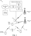
- Figure 1 depicts a wireless communication system 100 for sidelink control information indication, according to embodiments of the disclosure.
- the wireless communication system 100 includes remote units 105, base units 110, and communication links 115. Even though a specific number of remote units 105, base units 110, and communication links 115 are depicted in Figure 1 , one of skill in the art will recognize that any number of remote units 105, base units 110, and communication links 115 may be included in the wireless communication system 100.
- the wireless communication system 100 is compliant with the LTE, LTE advanced and subsequent cellular network system specified in the 3GPP specifications. More generally, however, the wireless communication system 100 may implement some other open or proprietary communication network, for example, WiMAX, among other networks.
- WiMAX wireless access control
- the remote units 105 may include computing devices, such as desktop computers, laptop computers, personal digital assistants ("PDAs"), tablet computers, smart phones, smart televisions (e.g., televisions connected to the Internet), smart appliances (e.g., appliances connected to the Internet), set-top boxes, game consoles, security systems (including security cameras), vehicle on-board computers, network devices (e.g., routers, switches, modems), or the like.
- the remote units 105 include wearable devices, such as smart watches, fitness bands, optical head-mounted displays, or the like.
- the remote units 105 may be referred to as subscriber units, mobiles, mobile stations, users, terminals, mobile terminals, fixed terminals, subscriber stations, UE, user terminals, a device, or by other terminology used in the art.
- the remote units 105 may communicate directly with one or more of the base units 110 via uplink ("UL") and downlink ("DL") communication signals.
- the UL and DL communication signals may be carried over the communication links 115.
- the remote units 105 may communicate indirectly with a base unit 110 via a relay unit 120.
- a relay unit 120 communicates with one or more remote units 105 using sidelink communication signals carried over one or more relay links 125.
- a relay unit 120 is a remote unit 105 that also serves as a relay for one or more additional remote units 105.
- the base units 110 may be distributed over a geographic region.
- a base unit 110 may also be referred to as an access terminal, a base, a base station, a Node-B, an eNB, a gNB, a Home Node-B, a relay node, a femtocell, an access point, a device, or by any other terminology used in the art.
- the base units 110 are generally part of a radio access network (“RAN") that may include one or more controllers communicably coupled to one or more corresponding base units 110. These and other elements of radio access network are not illustrated but are well known generally by those having ordinary skill in the art.
- the base units 110 connect to the mobile core network 130 via the RAN.
- the base units 110 may serve a number of remote units 105 within a serving area, for example, a cell or a cell sector via a wireless communication link.
- the base units 110 may communicate directly with one or more of the remote units 105 via communication signals.
- the base units 110 communicate directly with the one or more relay units 120 via the communication signals.
- the base units 110 transmit downlink ("DL") communication signals to serve the remote units 105 and/or relay units 120 in the time, frequency, and/or spatial domain.
- the DL communication signals may be carried over the communication links 115.
- the communication links 115 may be any suitable carrier in licensed or unlicensed radio spectrum.
- the communication links 115 facilitate communication between one or more of the remote units 105 (and/or relay units 120) and one or more of the base units 110.
- the wireless communication system 100 includes one or more relay units 120 capable of relaying traffic of the remote units 105 to the base units 110.
- the relay units 120 are remote units 105 capable of relaying the traffic between a base unit 110 and another remote unit 105.
- a relay unit maintains its own network connections.
- a relay unit 120 may communicate with a remote host 155 via a network connection with a base unit 110 and the mobile core network 130.
- the remote units 105 and relay units 120 communicate using relay links 125.
- the relay links 125 may be any suitable carrier in licensed or unlicensed radio spectrum. Examples of relay links 125 include, but are not limited to LTE-direct links, WiFi-direct links, and the like.
- the mobile core network 130 is an evolved packet core ("EPC"). In another embodiment, the mobile core network 130 may be a 5G core network. The mobile may be coupled to a data network 150, like the Internet and private data networks, among other data networks. In some embodiments, the remote units 105 and/or relay units 120 communicate with a remote host 155 via a network connection with the mobile core network 130. Each mobile core network 130 belongs to a single public land mobile network (“PLMN"). The present disclosure is not intended to be limited to the implementation of any particular wireless communication system architecture or protocol.
- PLMN public land mobile network
- the mobile core network 130 includes several network elements. As depicted, the mobile core network 130 includes at least one MME 135, at least one S-GW 140, and at least one P-GW 145. Although a specific number of MMEs 135, S-GWs 140, and P-GWs 145 are depicted in Figure 1 , one of skill in the art will recognize that any number of MMEs 135, S-GWs 140, and P-GWs 145 may be included in the mobile core network 130.
- the MME 135 is a control plane network element that handles signaling related to mobility and security for the remote unit 105.
- the MME 135 is a termination point for a NAS connection of the remote unit 105 to the mobile core network 130.
- the S-GW 140 is a user plane element that connects the RAN to the mobile core network 130.
- the S-GW 140 serves the remote unit 105 by routing incoming/outgoing IP packets.
- the P-GW 145 is a user plane element that connects the mobile core network 130 to an external (IP) network, such as the data network 150.
- IP external
- a relay unit 120 may provide a remote unit 105 with access to a base unit 110.
- a relay unit 120 used sidelink communications to communicate with one or more remote units 105.
- the relay unit 120 may indicate a transmission-reception pattern to the remote unit 105, e.g., using sidelink control information ("SCI") sent on a PSCCH, as discussed in greater detail below.
- SCI sidelink control information
- the remote unit 105 and/or relay unit 120 may indicate whether a SCI message includes feedback information and/or is associated with a data transmission on the sidelink data channel, as discussed in greater detail below.
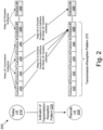
- Figure 2 depicts communication 200 for sidelink control information indication between a remote UE 205 and a relay UE 210, according to embodiments of the disclosure.
- the remote UE 205 may be one embodiment of a remote unit 105
- the relay UE 210 may be one embodiment of a relay unit 120.
- the remote UE 205 and relay UE 210 communicate using sidelink communication over a D2D connection.
- the sidelink communication includes a plurality of subframes 225-250. As depicted, a first portion of the subframes are Relay UE Transmission subframes and a second portions of the subframes are Relay UE Reception subframes.
- the relay UE 210 is scheduled to transmit data, signaling, feedback information, and the like to one or more remote UEs 205.
- the relay UE 210 is scheduled to receive data, signaling, feedback information, and the like from the one or more remote UEs.
- the number and location of the Relay UE Transmission subframes and Relay UE Reception subframes forms the transmission-reception pattern 215 for the sidelink communication.
- the relay UE 210 In order for the remote UE 205 and the relay UE 210 to successfully communicate each must know the transmission-reception pattern 215.
- the relay UE 210 generates the transmission-reception pattern 215 and transmits an indicator of the transmission-reception pattern (item 220) to the remote UE 205.
- the relay UE 210 when the relay UE 210 transmits a data transmission, the relay UE 210 needs to determine and generate an indicator 220 of the transmission-reception pattern 215 so that the remote UE 205 can identify at least one Relay UE Reception subframe, as shown in Figure 2 .
- the remote UE 205 provides feedback of the decoding status (e.g., HARQ ACK/NACK) of one or more data transmission(s) it receives from the relay UE 210.
- the decoding status e.g., HARQ ACK/NACK
- the relay UE 210 determines the transmission-reception pattern 215 for sidelink communication between one or more remote UE(s) 205. After determining the transmission-reception pattern 215, the relay UE 210 generates an indicator 220 of the transmission-reception pattern. In some embodiments, the indicator 220 of the transmission-reception pattern is transmitted in a sidelink control information ("SCI") message.
- SCI sidelink control information
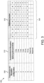
- the relay UE 210 determines the transmission-reception pattern 215 by selecting from a set of predefined patterns.
- Figure 3 shows a table of eight different predefined patterns.
- the transmission-reception pattern 215 is selected based on the ratio of payload size to be transmitted between relay UE 210 and remote UE 205 on sidelink.
- the payload size of the relay UE 210 is based on the payload size to be transmitted from the relay UE 210 to the remote UE 205.
- the payload size of the remote UE 205 is based on the payload size to be transmitted from the remote UE 205 to the relay UE 210.
- the information of payload (size) of the remote UE 205 may be obtained via a SR (scheduling request) or a BSR (Buffer Status Report) received by an eNB or relay UE 210.
- the buffer status of the relay UE 210 is used for the relay UE 210 to determine the number of relay UE transmission subframes (e.g., the number of reception subframes for the remote UE 205).
- the information of buffer status of the relay UE 210 is based on triggered traffic on the relay UE 210 side.
- the buffer status report ("BSR") of the remote UE 205 is based on the triggered traffic on the remote UE 205 side.
- the remote UE 205 reports the BSR to the relay UE 210 in a BSR MAC control element (e.g., transmitted in UL data channel for legacy UE to eNB transmission).
- the relay UE 210 may determine the number of relay UE reception subframe (e.g., the number of transmission subframes for the remote UE).
- the transmission-reception pattern 215 is generated by the relay UE 210 and may or may not conform to one of the predefined patterns.
- the generated transmission-reception pattern 215 may also be based on the ratio of payload size to be transmitted between relay UE 210 and remote UE 205 on sidelink.
- the relay UE 210 transmits data to the remote UE 205 in four subframes 225-240 and the remote UE 205 receives the data during these subframes.
- the remote UE 205 is to respond to the four subframes transmissions in one subframe.
- the payload size ratio is 4:1 and the transmission-reception pattern 215 is four transmission subframes on relay UE 210 side to one reception subframe on relay UE 210 side.
- the transmission-reception pattern 215 may be represented in bitmap manner, e.g., 5 bits (11110), in sidelink control information.
- a value of "1" in the bitmap indicates that the subframe is a Relay UE Transmission subframe
- a value of "0" indicates that the subframe is a Relay UE Reception subframe.
- the transmission-reception pattern 215 may be generated by the eNB, e.g., based on the ratio of payload size to be transmitted between relay UE 210 to and remote UE(s) 205 on sidelink. In such embodiments, the transmission-reception pattern 215 is then transmitted from the eNB (not shown) to the relay UE 210. Alternatively, the eNB may transmit the transmission-reception pattern 215 to both relay UE 210 and remote UE(s) 205 by downlink control information.
- the indicator 220 of the transmission-reception pattern may be an indication of one or more next reception subframes on the relay UE 210 side (e.g., indicate Relay UE Reception subframes).
- the relay UE 210 may determine the next one reception subframe (e.g., to receive the transmission from the remote UE 205) and then the relay UE 210 generates an indicator of next one reception subframe pattern.
- a 4-bit value of "0111" may be included in SCI to indicate that the n+7 subframe is used for relay UE 210 reception (i.e., receiving and detecting remote UE 205 transmission).
- the indicator of a next reception subframe must point to a subframe far enough ahead in time for the remote UE 205 to process the SCI and switch to transmission mode.
- the relay UE 210 may send an indicator with a value of "0100" (binary "4") during subframe #0 (subframe 225) to indicate that the next relay UE reception subframe is n+4 subframes away (e.g., the next UE reception subframe is subframe #4).
- the indicator may have a value of "0011” (binary "3") and in subframe #2 (subframe 235) the indicator may have a value of "0010" (binary "2”), each indicator pointing to the subframe #4 (subframe 245) as the next relay UE reception subframe.
- the indicator may have a value of "0110" (binary "6") to indicate that the next relay UE reception subframe is n+4 subframes away (e.g., the next UE reception subframe is subframe #9).
- the indicator 220 of the transmission-reception pattern may be an indication of one or more next transmission subframes on the relay UE 210 side (e.g., indicate Relay UE Transmission subframes).
- Figure 3 depicts a table 300 with predetermined transmission-reception patterns 325.
- 'T' represents the transmission subframe(s) on relay UE 210 side
- 'R' represents the reception subframe(s) on relay UE 210 side).
- the table 300 includes a transmission-to-reception configuration 305.
- Each transmission-to-reception configuration 305 corresponds to one of the predetermined transmission-reception patterns 325.
- the relay UE 210 may send, as the indicator 220, a binary value corresponding to the transmission-to-reception configuration 305.
- the table 300 also includes transmission-to-reception switch-point periodicity information 310 when indicates a periodicity with which a predetermined transmission-reception pattern 325 switches from relay UE transmission to relay UE reception, and back again.
- the transmission-reception pattern 215 shown in Figure 2 may correspond to the transmission-to-reception configuration #3 and have a transmission-to-reception switch-point periodicity of 5ms (each subframe being 1ms in duration).
- the relay UE 210 transmits the indicator 220 of the transmission-reception pattern to the remote UE 205.
- the indicator 220 is sent in a SCI message.
- the indicator 220 of pattern may be represented by a plurality of bits (e.g., 3, 4 or 5 bits) in the SCI.
- a bitmap indicator 220 of the transmission-reception pattern may use 5 bits to represent the transmission-reception pattern 215 in the following 5 subframes.
- a '1' may be used to represent a transmission subframe and a '0' may be used to represent a reception subframe.
- the transmission-reception pattern 215 may be indicated using the bitmap "11110".
- the indicator 220 of the transmission-reception pattern may use one or more bits to indicate the next one reception subframe (or alternative the next one transmission subframe).
- a four-bit indicator 220 of "0111" may be used to indicate that the n+7 subframe is used for relay UE 210 reception (e.g., the remote UE 205 may transmit data or feedback information in this subframe).
- a three-bit indicator 220 of "110" may be used to indicate that the n+6 subframe is to be used for relay UE transmission (e.g., the remote UE 205 is to receive data or feedback information in this subframe).
- the indicator 220 may include one or more bits representing one of a set of pre-defined transmission-reception patterns 215.
- a three-bit indicator 220 may be used to represent one of a set of pre-defined pattern configurations in Figure 3 .
- an indicator 220 of '100' indicates the transmission-to-reception configuration #4 where the first nine subframes (subframe 0-8) in one frame (10ms) are used for relay UE 210 transmission and the last subframe (subframe 9) is used for relay UE 210 reception.
- the indicator 220 may include additional information.
- an indicator of scheduling assignment (“SA") may indicate a time/frequency resource of feedback information.
- an indicator of SA may indicate a time offset and/or frequency offset based on the transmission resource of the relay UE 210.
- an indicator of SA may indicate the time offset only.
- the frequency resource is same as relay UE 210 transmission (SA and/or data) resource.
- the time offset is preconfigured or fixed (e.g., n+4) and the frequency resource is same as the relay UE 210 transmission (SA and/or data) resource.
- the indicator 220 may indicate a preconfigured or fixed time/frequency offset for resource hopping.
- the relay UE 210 may send the indicator 220 of the transmission-reception pattern in a SCI message.
- the SCI transmitted from relay UE 210 to remote UE 205 may include a flag for scheduling assignment function differentiation.
- the SA function differentiation flag may be a 1- or 2-bit flag used to differentiate a SA is used to indicate its associated data transmission from a feedback ACK/NACK information transmission.
- the SA function differentiation flag aids the remote UE 205 in interpreting the SCI message.
- the SA function differentiation flag is a 1-bit flag that indicates whether this SCI includes only an indication of feedback information transmission or whether it includes both an indication of data transmission and an indication of feedback information transmission. For example, a value of '0' may indicate that the SCI message contains an indication of feedback information, while a value of '1' may indicate that this SCI message include both an indication of data transmission and the indication of feedback information. Alternatively, a value of '1' may indicate that this SCI includes only an indication of feedback information, while a value of '0' may indicate that this SCI includes both an indication of data transmission and an indication of feedback information.
- the SA function differentiation flag is further explained with reference to Figure 4 .
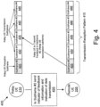
- Figure 4 depicts communication 400 for sidelink control information indication between the remote UE 205 and the relay UE 210, according to embodiments of the disclosure. Note that the remote UE 205 and the relay UE 210 communicate over sidelink using a transmission-reception pattern 415 where the subframe 425 (subframe #0) is a Relay UE Reception Subframe and the subframes 430-445 are Relay UE Transmission Subframes.
- subframe 425 subframe #0
- the subframes 430-445 are Relay UE Transmission Subframes.
- the relay UE 210 receives a data transmission from the remote UE 205 in subframe #0 (subframe 425) and attempts to transmit feedback information (e.g., HARQ feedback) corresponding to subframe #0 (subframe 425) in subframe #2 (relay UE 210 transmission subframe).
- feedback information e.g., HARQ feedback
- the remote UE 205 does not know a priori (e.g., it cannot foresee) whether the relay UE 210 has data to be transmitted in subframe #2 to remote UE 205 or whether the relay UE 210 only has feedback information to transmit.
- the SA function differentiation flag is included in SCI transmitted by the relay UE 210 so that the remote UE 205 is able to determine whether the SCI transmitted in subframe #2 includes an indication of feedback information transmission only or whether this SCI includes both an indication of data transmission and an indication of feedback information.
- the SA function differentiation flag may be a 1-bit flag to indicate whether this sidelink control information includes an indication of data transmission or whether this sidelink control information includes ACK/NACK feedback information.
- the SCI will not have both an indication of data transmission and ACK/NACK feedback information.
- a value of '0' may indicate that this SCI includes an indication of data transmission only, while a value of '1' may indicate that this SCI includes an indication of feedback information only.
- a value of '1' may indicate that this SCI includes an indication of data transmission only, while a value of '0' may indicate that this SCI includes an indication of feedback information only.
- the SA function differentiation flag may be a 2-bit flag that indicates whether this SCI includes an indication of data transmission only (e.g., indicated using a value of '00'), whether this SCI includes an indication of feedback information transmission only (e.g., indicates using a value of '01'), or whether this SCI includes both an indication of data transmission and feedback information transmission (e.g., indicated using a value '10').
- the 2-bit flag e.g., the value '11'
- is reserved e.g., not to be used.
- the content of the SCI varies based on the SA function differentiation flag. For example, if the flag for SA function differentiation is set to indicate data transmission only, then the SCI should include the following bits to indicate data transmission relevant information: a HARQ process number (e.g., 3 bits); a resource allocation indication of SA associated data (e.g., 12bits); a time gap between the SA and its associated data (e.g., 4bits), a frequency resource location of SA associated data (e.g., 8bits), or some combination thereof; a modulation and coding scheme (e.g., 5 bits); a modulation and coding scheme of SA associated data (e.g., 5 bits); and a new data indicator (e.g., 1 bit).
- the time gap information is used to support FDM between PSCCH/PSSCH from the system perspective, but TDM from the UE perspective.
- the SCI may be modified to indicate ACK/NACK feedback relevant information.
- the above bits of HARQ process number (3bits) and modulation and coding scheme (5bits) may be used to indicate ACK/NACK feedback in bit manner.
- these 8 bits may represent the decoding status of 8 HARQ process numbers in bitmap manner, e.g., using '1' to represent ACK status and '0' to represent NACK status.
- one or more of these bits may be used to indicate DTX status where the remote UE 205 did not use this HARQ process number for transmission.
- the remote UE 205 if it transmitted the data transmission with HARQ process number, it will check the corresponding HARQ process number bit of 8bits.
- the value of '01111011' can represent HARQ process #7 and #2 are decoded unsuccessfully or didn't used for transmission, while the other processes (e.g., #6, #5, #4, #3, #1, and #0) are decoded successfully.
- the SCI may indicate both data transmission relevant information and ACK/NACK feedback relevant information.
- this may require new bit fields to be defined for HARQ ACK/NACK feedback in SCI.
- a new 8-bit field may be defined to convey HARQ feedback information in the manner described above.
- Figure 5 depicts communication 500 for sidelink control information indication between the remote UE 205 and the relay UE 210, according to embodiments of the disclosure.
- the remote UE 205 sends SCI and associated data to the relay UE 210.
- the remote UE 205 first determines the transmission subframe for sidelink communication based on transmission and reception configuration (e.g., based on the transmission-reception pattern 515).
- the transmission and reception configuration may be received from relay UE 210 in sidelink control information.
- the relay UE 210 may send SCI containing the indicator 220 of the transmission-reception pattern discussed above.
- the transmission and reception configuration may be received from an eNB (not shown) in downlink control information.
- the remote UE 205 determines to transmit SCI containing an indicator of feedback information and an indicator of associated data in subframe 530 ("Subframe #1).
- the remote UE 205 generates an indicator of HARQ feedback information based on the decoding status of each relay UE 210 transmission subframe.
- the indicator of HARQ feedback information may be a bitmap (e.g., 8-bit bitmap), e.g., using '1' to represent ACK status and '0' to represent NACK status.
- the relay UE 210 cannot know ahead of time whether the remote UE 205 will transmit feedback information, an indicator of data transmission, or both feedback information and an indicator of data transmission in the SCI of Subframe #1 (subframe 530), the generates a flag for SA function differentiation.
- the SA function differentiation flag generated by the remote UE 205 is substantially as that generated by the relay UE 210 described above.
- the remote UE 205 Because there is an associated data transmission (e.g., the remote UE 205 transmits data on same subframe), the remote UE 205 generates the additional data transmission relevant information in SCI as discussed above. Then in Subframe #1, the remote UE 205 transmits the indicator 520 of (HARQ) feedback information and indication of associated data transmission in SCI. Here, the remote UE 205 transmits the associated data using the sidelink data channel.
- the remote UE 205 transmits the associated data using the sidelink data channel.
- the remote UE 205 and/or the relay UE 210 may reuse the SCI format 1 when sending the above described indicators in SCI.
- certain bit fields of the SCI format 1 are replaces with the above described indicators, requiring a receiving UE to reinterpret the SCI format 1 in order to receive the indicators.
- the SCI format 1 contains 3 bits of priority information, 4 bits of resource reservation, a system-specific number of bits of frequency resource location of initial transmission and retransmission (e.g., using log 2 N subchannel SL N subchannel SL + 1 / 2 bits, where N subchannel SL refers to the number of subchannels allocated for sidelink communication), 4 bits of time gap information (time gap between initial transmission and retransmission), 5 bits of modulation and coding scheme information, 1 bit for a retransmission index, and a balance of reserved information bits so that the size of the SCI format 1 message is 32-bits in total (the reserved bits are typically set to '0').
- a system-specific number of bits of frequency resource location of initial transmission and retransmission e.g., using log 2 N subchannel SL N subchannel SL + 1 / 2 bits, where N subchannel SL refers to the number of subchannels allocated for sidelink communication
- 4 bits of time gap information time gap between initial transmission and retransmission
- one or more bit fields may be used to carry new information.
- the 3 bits of priority information may be used to represent the HARQ process number (a 3-bit value) and the retransmission index may be used to represent the new data indicator.
- the 4 resource reservation bits may be used to indicate the transmission-reception pattern. Where the transmission-reception pattern can be represented with 3 bits, the remaining resource reservation bit may be used to represent the SA function differentiation flag. In other embodiments, the reserved information bits may be used to indicate the transmission-reception pattern and SA function differentiation flag.
- the priority bits and modulation and coding scheme bits may be used to represent the decoding status (HARQ ACK/NACK) of 8 HARQ process number in bitmap manner as discussed above. Additionally (or alternatively) bits of the reserved information bits may be used to indicate the HARQ ACK/NACK feedback indication.
- Figure 6 depicts one embodiment of a remote UE apparatus 600 that may be used for sidelink control information indication, according to embodiments of the disclosure.
- the remote UE apparatus 600 may be one embodiment of the remote unit 105 and/or the remote UE 205.
- the remote UE apparatus 600 includes a processor 605, a memory 610, an input device 615, a display 620, a transmitter 625, and a receiver 630.
- the input device 615 and the display 620 are combined into a single device, such as a touchscreen.
- the remote unit 105 may not include any input device 615 and/or display 620.
- the transmitter 625 and receiver 630 are used to communicate with a relay UE using sidelink communication.
- the sidelink communication is defined within preconfigured sidelink resource pools (PSCCH/PSSCH). Multiple pools can be configured by eNB for sidelink operation.
- the sidelink communication uses frequency-division multiplexing ("FDM") between PSCCH and PSSCH, from both a UE and system perspective.
- FDM frequency-division multiplexing
- the sidelink communication uses FDM between PSCCH and PSSCH from the system perspective, but uses time-division multiplexing ("TDM”) from the UE perspective.
- the processor 605 may include any known controller capable of executing computer-readable instructions and/or capable of performing logical operations.
- the processor 605 may be a microcontroller, a microprocessor, a central processing unit (“CPU"), a graphics processing unit (“GPU”), an auxiliary processing unit, a field programmable gate array (“FPGA”), or similar programmable controller.
- the processor 605 executes instructions stored in the memory 610 to perform the methods and routines described herein.
- the processor 605 is communicatively coupled to the memory 610, the input device 615, the display 620, the transmitter 625, and the receiver 630.
- the receiver 630 receives an indicator of a transmission-reception pattern in a first control information message.
- the receiver 630 may also receive an indicator of scheduling assignment transmitted in the first control information message and associated data transmitted in a data message from a relay unit.
- the processor 605 In response to receiving one or more data processes (e.g., HARQ processes), and according to the invention, the processor 605 generates an indicator of hybrid automatic repeat request ("HARQ") feedback information.
- the processor 605 also determines a transmission subframe of the apparatus based on the received indicator of a transmission-reception pattern.
- the processor 605 may then control the transmitter 625 to transmit the indicator of HARQ feedback information to the relay unit in a second control information message on a remote unit transmission subframe determined from the transmission-reception pattern.
- HARQ hybrid automatic repeat request
- receiving the indicator of the transmission-reception pattern includes the receiving a SCI format 1 message and reinterpreting the SCI format 1 message to determine the indicator of the transmission-reception pattern.
- receiving the indicator of the transmission-reception pattern includes receiving the indicator of the transmission-reception pattern from the relay unit. In another embodiment, receiving the indicator of the transmission-reception pattern includes receiving the indicator of the transmission-reception pattern from a base unit.
- the indicator of the transmission-reception pattern may indicate a particular pattern selected from a plurality of predetermined patterns.
- the indicator of the transmission-reception pattern comprises a bitmap representing at least one transmission subframe and at least one reception subframe in the transmission-reception pattern.
- the indicator of the transmission-reception pattern is an offset value for instance pointing to a next reception subframe in the transmission-reception pattern.
- the indicator of the transmission-reception pattern is an offset value pointing to a next transmission subframe in the transmission-reception pattern.
- the second control information message includes a scheduling assignment ("SA") function differentiation flag that indicates whether the second control information message includes HARQ feedback information and whether a data transmission is associated with the second control information message. Additionally, the second control information message may also include a data offset indicating a time offset between the second control information message and the associated data transmission.
- SA scheduling assignment
- the memory 610 in one embodiment, is a computer readable storage medium.
- the memory 610 includes volatile computer storage media.
- the memory 610 may include a RAM, including dynamic RAM (“DRAM”), synchronous dynamic RAM (“SDRAM”), and/or static RAM (“SRAM”).
- the memory 610 includes non-volatile computer storage media.
- the memory 610 may include a hard disk drive, a flash memory, or any other suitable non-volatile computer storage device.
- the memory 610 includes both volatile and non-volatile computer storage media.
- the memory 610 stores data relating to sidelink control information indication, for example storing transmission-reception patterns, indicators, feedback information, and the like.
- the memory 610 also stores program code and related data, such as an operating system or other controller algorithms operating on the remote unit 105 and one or more software applications.
- the input device 615 may include any known computer input device including a touch panel, a button, a keyboard, a stylus, a microphone, or the like.
- the input device 615 may be integrated with the display 620, for example, as a touchscreen or similar touch-sensitive display.
- the input device 615 includes a touchscreen such that text may be input using a virtual keyboard displayed on the touchscreen and/or by handwriting on the touchscreen.
- the input device 615 includes two or more different devices, such as a keyboard and a touch panel.
- the display 620 may include any known electronically controllable display or display device.
- the display 620 may be designed to output visual, audible, and/or haptic signals.
- the display 620 includes an electronic display capable of outputting visual data to a user.
- the display 620 may include, but is not limited to, an LCD display, an LED display, an OLED display, a projector, or similar display device capable of outputting images, text, or the like to a user.
- the display 620 may include a wearable display such as a smart watch, smart glasses, a heads-up display, or the like.
- the display 620 may be a component of a smart phone, a personal digital assistant, a television, a table computer, a notebook (laptop) computer, a personal computer, a vehicle dashboard, or the like.
- the display 620 includes one or more speakers for producing sound.
- the display 620 may produce an audible alert or notification (e.g., a beep or chime).
- the display 620 includes one or more haptic devices for producing vibrations, motion, or other haptic feedback.
- all or portions of the display 620 may be integrated with the input device 615.
- the input device 615 and display 620 may form a touchscreen or similar touch-sensitive display.
- the display 620 may be located near the input device 615.
- the transmitter 625 and receiver 630 operate under the control of the processor 605 to transmit messages, data, and other signals and also to receive messages, data, and other signals.
- the processor 605 may selectively activate the transmitter 625 or receiver 630 (or portions thereof) at particular times in order to send and/or receive messages.
- the remote UE apparatus 600 may include one or more transmitters 625 and one or more receivers 630 for communicating with the relay UE 120 (or relay UE 210).
- Figure 7 depicts one embodiment of a relay UE apparatus 700 that may be used for sidelink control information indication, according to embodiments of the disclosure.
- the relay UE apparatus 700 may be one embodiment of the relay unit 120 and/or the relay UE 210.
- the relay UE apparatus 700 includes a processor 705, a memory 710, an input device 715, a display 720, a transmitter 725, and a receiver 730.
- the input device 715 and the display 720 are combined into a single device, such as a touchscreen.
- the remote unit 105 may not include any input device 715 and/or display 720.
- the transmitter 725 and receiver 730 are used to communicate with a relay UE using sidelink communication.
- the sidelink communication is defined within preconfigured sidelink resource pools (PSCCH/PSSCH). Multiple pools can be configured by eNB for sidelink operation.
- the sidelink communication uses frequency-division multiplexing ("FDM") between PSCCH and PSSCH, from both a UE and system perspective.
- FDM frequency-division multiplexing
- the sidelink communication uses FDM between PSCCH and PSSCH from the system perspective, but uses time-division multiplexing ("TDM”) from the UE perspective.
- the processor 705, in one embodiment, may include any known controller capable of executing computer-readable instructions and/or capable of performing logical operations.
- the processor 705 may be a microcontroller, a microprocessor, a central processing unit (“CPU"), a graphics processing unit (“GPU”), an auxiliary processing unit, a field programmable gate array (“FPGA”), or similar programmable controller.
- the processor 705 executes instructions stored in the memory 710 to perform the methods and routines described herein.
- the processor 705 is communicatively coupled to the memory 710, the input device 715, the display 720, the transmitter 725, and the receiver 730.
- the receiver 730 receives a second control information message from a remote unit over sidelink communication.
- the second control information message is in response to the remote unit receiving one or more data processes scheduled by a first control information message from a relay unit, e.g., from the relay UE apparatus 700.
- the processor 705 determines a transmission-reception pattern for the sidelink communication between the relay UE apparatus 700 and the remote UE.
- the processor 705 also generates an indicator of the determined transmission-reception pattern.
- the processor 705 may then control the transmitter 725 to transmit the indicator of the determined transmission-reception pattern to the remote unit in a third control information message.
- the first control information message, the second control information message, and the third control information message are transmitted in a same type of control channel (e.g., PSCCH).
- the processor 705 determines the transmission-reception pattern comprises by determining a ratio of transmission payload to reception payload based on a buffer status of relay unit and/or a buffer status report of one or more remote units. The processor 705 may then generate the transmission-reception pattern based on one or more of: the ratio, the buffer status of relay unit, and the buffer status report of one or more remote units.
- the indicator of the determined transmission-reception pattern comprises a bitmap representing at least one transmission subframe and at least one reception subframe in the generated transmission-reception pattern.
- the indicator of the determined transmission-reception pattern is an offset value pointing to a next reception subframe in the generated transmission-reception pattern.
- the indicator of the determined transmission-reception pattern is an offset value pointing to a next transmission subframe in the generated transmission-reception pattern.
- the processor 705 determines the transmission-reception pattern comprises by determining a ratio of transmission payload to reception payload based on a buffer status of relay unit and/or a buffer status report of one or more remote units. The processor 705 may then the transmission-reception pattern from a plurality of predetermined patterns based on one or more of: the ratio, the buffer status of relay unit, and the buffer status report of one or more remote units.
- the indicator of the determined transmission-reception pattern may be a plurality of bits representing the selected transmission-reception pattern. For example, specific bit values may be mapped to specific patterns among the plurality of predetermined patterns.
- third control information message includes an indicator of scheduling assignment ("SA") function differentiation flag.
- SA function differentiation flag may indicate whether the third control information message includes hybrid automatic repeat request (“HARQ") feedback information.
- HARQ hybrid automatic repeat request
- the third control information message may contain a bitmap representing HARQ feedback information corresponding to one or more HARQ processes.
- the third control information message includes an indicator of scheduling assignment.
- the indicator of scheduling assignment indicating an associated data transmission.
- the third control information message may include a data offset indicating a time offset between the second SCI message and the associated data transmission.
- the memory 710 in one embodiment, is a computer readable storage medium.
- the memory 710 includes volatile computer storage media.
- the memory 710 may include a RAM, including dynamic RAM (“DRAM”), synchronous dynamic RAM (“SDRAM”), and/or static RAM (“SRAM”).
- the memory 710 includes non-volatile computer storage media.
- the memory 710 may include a hard disk drive, a flash memory, or any other suitable non-volatile computer storage device.
- the memory 710 includes both volatile and non-volatile computer storage media.
- the memory 710 stores data relating to sidelink control information indication, for example storing transmission-reception patterns, indicators, feedback information, and the like.
- the memory 710 also stores program code and related data, such as an operating system or other controller algorithms operating on the relay UE apparatus 700 and one or more software applications.
- the input device 715 may include any known computer input device including a touch panel, a button, a keyboard, a stylus, a microphone, or the like.
- the input device 715 may be integrated with the display 720, for example, as a touchscreen or similar touch-sensitive display.
- the input device 715 includes a touchscreen such that text may be input using a virtual keyboard displayed on the touchscreen and/or by handwriting on the touchscreen.
- the input device 715 includes two or more different devices, such as a keyboard and a touch panel.
- the display 720 may include any known electronically controllable display or display device.
- the display 720 may be designed to output visual, audible, and/or haptic signals.
- the display 720 includes an electronic display capable of outputting visual data to a user.
- the display 720 may include, but is not limited to, an LCD display, an LED display, an OLED display, a projector, or similar display device capable of outputting images, text, or the like to a user.
- the display 720 may include a wearable display such as a smart watch, smart glasses, a heads-up display, or the like.
- the display 720 may be a component of a smart phone, a personal digital assistant, a television, a table computer, a notebook (laptop) computer, a personal computer, a vehicle dashboard, or the like.
- the display 720 includes one or more speakers for producing sound.
- the display 720 may produce an audible alert or notification (e.g., a beep or chime).
- the display 720 includes one or more haptic devices for producing vibrations, motion, or other haptic feedback.
- all or portions of the display 720 may be integrated with the input device 715.
- the input device 715 and display 720 may form a touchscreen or similar touch-sensitive display.
- the display 720 may be located near the input device 715.
- the transmitter 725 and receiver 730 operate under the control of the processor 705 to transmit messages, data, and other signals and also to receive messages, data, and other signals.
- the processor 705 may selectively activate the transmitter 725 or receiver 730 (or portions thereof) at particular times in order to send and/or receive messages.
- the relay UE apparatus 700 may include one or more transmitters 725 and one or more receivers 730 for communicating with a remote UE 105 and/or a base unit 110 of a mobile communication network.
- Figure 8 depicts a method 800 for sidelink control information indication, according to embodiments of the disclosure.
- the method 800 is performed by an apparatus, such as the relay unit 120, the relay UE 210, and/or relay UE apparatus 700.
- the method 800 may be performed by a processor executing program code, for example, a microcontroller, a microprocessor, a CPU, a GPU, an auxiliary processing unit, a FPGA, or the like.
- the method 800 begins and receives 805 second control information message from a remote unit over sidelink communication.
- the second control information message is in response to the remote unit receiving one or more data processes scheduled by a first control information message from a relay unit.
- the first control information message includes a transmission-reception pattern, wherein the second control information message is received during a reception period of the transmission-reception pattern.
- the method 800 includes determining 810 a transmission-reception pattern for a remote unit using sidelink communication.
- determining 810 the transmission-reception pattern includes determining a ratio of transmission payload to reception payload based on a buffer status of relay unit and/or a buffer status report of one or more remote units, and further generating the transmission-reception pattern based one or more of: on the ratio, the buffer status of relay unit, and the buffer status report of one or more remote units.
- determining the transmission-reception pattern includes selecting the transmission-reception pattern from a plurality of predetermined patterns based one or more of: on the ratio, the buffer status of relay unit, and the buffer status report of one or more remote units, wherein the indicator of the determined transmission-reception pattern comprises a plurality of bits representing the selected transmission-reception pattern.
- the method 800 includes generating 815 an indicator of the determined transmission-reception pattern.
- generating 815 an indicator of the determined transmission-reception pattern includes generating a SCI format 1 message to be reinterpreted by the remote unit to indicate the determined transmission-reception pattern.
- the indicator of the determined transmission-reception pattern comprises a bitmap representing at least one transmission subframe and at least one reception subframe in the generated transmission-reception pattern.
- the indicator of the determined transmission-reception pattern is an offset value pointing to a next reception subframe in the generated transmission-reception pattern.
- the indicator of the determined transmission-reception pattern is an offset value pointing to a next transmission subframe in the generated transmission-reception pattern.
- the transmission-reception pattern is selected from a plurality of predetermined patterns
- the indicator of the determined transmission-reception pattern may be a plurality of bits representing the selected transmission-reception pattern.
- the method 800 includes transmitting 820 the indicator to the remote unit in a third control information message.
- the first control information message, the second control information message, and the third control information message are transmitted in a same type of control channel (e.g., PSCCH).
- the third control information message includes an indicator of scheduling assignment ("SA") function differentiation flag, the SA function differentiation flag indicating that the third control information message includes hybrid automatic repeat request (“HARQ") feedback information.
- SA scheduling assignment
- HARQ hybrid automatic repeat request
- the third control information message may include a bitmap representing the HARQ feedback information in response to one or more HARQ process.
- the third control information message includes an indicator of scheduling assignment, the indicator of scheduling assignment indicating that a data transmission is associated with the third control information message.
- the third control information message may further include a data offset indicating a time offset between the third control information message and the associated data transmission.
- the remote unit sends a fourth control information message in response to the transmitting 820 of the indicator to the remote unit.
- the fourth control information message includes an indicator of whether the fourth control information message contains ("HARQ") feedback information.
- the fourth control information message may include an indicator of whether the fourth control information message is associated with a data transmission from the remote unit. The method 800 ends.
- Figure 9 depicts a method 900 for sidelink control information indication, according to embodiments of the disclosure.
- the method 900 is performed by an apparatus, such as the remote unit 105, the remote UE 205, and/or the remote UE apparatus 600.
- the method 900 may be performed by a processor executing program code, for example, a microcontroller, a microprocessor, a CPU, a GPU, an auxiliary processing unit, a FPGA, or the like.
- the method 900 begins and receives 905 an indicator of a transmission-reception pattern in a first control information message.
- the first control information message is a sidelink control information ("SCI") message.
- the first control information message is a downlink control information (“DCI”) message.
- the method 900 includes receiving 910 an indicator of scheduling assignment transmitted in the first control information message and associated data transmitted in a data channel from a relay unit.
- the associated data is received via a sidelink data message.
- receiving 910 the indicator of the transmission-reception pattern comprises receiving a SCI format 1 message and reinterpreting the SCI format 1 message to determine the indicator of the transmission-reception pattern.
- receiving 910 the indicator of the transmission-reception pattern comprises receiving the indicator of the transmission-reception pattern from the relay unit.
- receiving 910 the indicator of the transmission-reception pattern comprises receiving the indicator of the transmission-reception pattern from a base unit.
- the method 900 includes generating 915 an indicator of hybrid automatic repeat request ("HARQ") feedback information in response to the received one or more data processes.
- the one or more data processes are one or more HARQ processes.
- the indicator of the transmission-reception pattern indicates a particular pattern selected from a plurality of predetermined patterns.
- the indicator of the transmission-reception pattern comprises a bitmap representing at least one transmission subframe and at least one reception subframe in the transmission-reception pattern.
- the indicator of the transmission-reception pattern is an offset value pointing to a next reception subframe in the transmission-reception pattern.
- the indicator of the transmission-reception pattern is an offset value pointing to a next transmission subframe in the transmission-reception pattern.
- the method 900 includes determining 920 a transmission subframe of the apparatus based on the received indicator of a transmission-reception pattern.
- the method 900 includes transmitting 925 the indicator of HARQ feedback information to the relay unit in a second control information message on a transmission subframe of remote unit determined from the transmission-reception pattern.
- the second control information message is a SCI message.
- the second control information message includes a scheduling assignment ("SA") function differentiation flag that indicates whether the second control information message includes HARQ feedback information and whether a data transmission is associated with the second control information message.
- the second control information message further includes a data offset indicating a time offset between the second control information message and the associated data transmission.
Landscapes
- Engineering & Computer Science (AREA)
- Computer Networks & Wireless Communication (AREA)
- Signal Processing (AREA)
- Mobile Radio Communication Systems (AREA)
Claims (6)
- Verfahren (800), das von einer ersten Benutzerausrüstung durchgeführt wird, das Verfahren umfassend:Empfangen (805) einer zweiten Steuerinformationsnachricht von einer zweiten Benutzerausrüstung über Sidelink-Kommunikation, wobei die zweite Steuerinformationsnachricht eine Reaktion darauf ist, dass die zweite Benutzerausrüstung einen oder mehrere Datenprozesse empfängt, die von einer ersten Steuerinformationsnachricht von der ersten Benutzerausrüstung geplant wurden;Bestimmen (810) eines Zeitversatzes für Feedback-Informationen einer hybriden automatischen Wiederholungsanforderung, HARQ, für die Sidelink-Kommunikation, wobei der Zeitversatz pro Sidelink-Ressourcenpool (vor)konfiguriert ist;Erzeugen (815) eines Indikators des bestimmten Zeitversatzes; undÜbertragen (820) des Indikators des bestimmten Zeitversatzes an die zweite Benutzerausrüstung in einer dritten Steuerinformationsnachricht.
- Verfahren (800) nach Anspruch 1, wobei die erste Steuerinformationsnachricht, die zweite Steuerinformationsnachricht und die dritte Steuerinformationsnachricht in einem Steuerkanal einer gleichen Art übertragen werden.
- Verfahren (800) nach Anspruch 1, wobei die dritte Steuerinformationsnachricht einen Indikator eines Funktionsdifferenzierungsflags für Planungszuweisung, SA, einschließt, wobei das SA-Funktionsdifferenzierungsflag angibt, dass die dritte Steuerinformationsnachricht Feedback-Informationen einer hybriden automatischen Wiederholungsanforderung, HARQ, einschließt, und
optional wobei die dritte Steuerinformationsnachricht eine Bitmap einschließt, die die HARQ-Feedbackinformationen als Reaktion auf einen oder mehrere HARQ-Prozesse darstellt. - Verfahren (800) nach Anspruch 1, wobei die dritte Steuerinformationsnachricht einen Indikator der Planungszuweisung einschließt, wobei der Indikator der Planungszuweisung angibt, dass eine Datenübertragung mit der dritten Steuerinformationsnachricht verknüpft ist, und
optional wobei die dritte Steuerinformationsnachricht ferner einen Datenversatz einschließt, der einen Zeitversatz zwischen der dritten Steuerinformationsnachricht und der verknüpften Datenübertragung angibt. - Verfahren (800) nach Anspruch 1, ferner umfassend das Empfangen einer vierten Steuerinformationsnachricht von der zweiten Benutzerausrüstung, wobei die vierte Steuerinformationsnachricht einen Indikator dafür einschließt, ob die vierte Steuerinformationsnachricht Feedback-Informationen einer hybriden automatischen Wiederholungsanforderung, HARQ, enthält, und
optional wobei die vierte Steuerinformationsnachricht ferner einen Indikator dafür einschließt, ob die vierte Steuerinformationsnachricht mit einer Datenübertragung von der zweiten Benutzerausrüstung verknüpft ist. - Einrichtung (120, 210, 700), umfassend Mittel zum Durchführen des Verfahrens nach einem der Ansprüche 1 bis 5.
Applications Claiming Priority (1)
| Application Number | Priority Date | Filing Date | Title |
|---|---|---|---|
| PCT/CN2017/083225 WO2018201448A1 (en) | 2017-05-05 | 2017-05-05 | Sidelink control information indication |
Publications (4)
| Publication Number | Publication Date |
|---|---|
| EP3619989A1 EP3619989A1 (de) | 2020-03-11 |
| EP3619989A4 EP3619989A4 (de) | 2020-11-04 |
| EP3619989B1 true EP3619989B1 (de) | 2025-04-09 |
| EP3619989C0 EP3619989C0 (de) | 2025-04-09 |
Family
ID=64016331
Family Applications (1)
| Application Number | Title | Priority Date | Filing Date |
|---|---|---|---|
| EP17908450.4A Active EP3619989B1 (de) | 2017-05-05 | 2017-05-05 | Sidelink-steuerinformationsanzeige |
Country Status (4)
| Country | Link |
|---|---|
| US (2) | US11153853B2 (de) |
| EP (1) | EP3619989B1 (de) |
| CN (1) | CN110771224A (de) |
| WO (1) | WO2018201448A1 (de) |
Families Citing this family (38)
| Publication number | Priority date | Publication date | Assignee | Title |
|---|---|---|---|---|
| EP3399825B1 (de) * | 2017-05-05 | 2020-02-19 | Nokia Technologies Oy | Reservieren von ressourcen in einer vorrichtung-zu-vorrichtung-kommunikation |
| EP3619989B1 (de) * | 2017-05-05 | 2025-04-09 | Motorola Mobility LLC | Sidelink-steuerinformationsanzeige |
| US11722262B2 (en) * | 2017-07-21 | 2023-08-08 | Lg Electronics Inc. | Method and apparatus for transmitting feedback by terminal receiving signal from another terminal in wireless communication system |
| EP3493450B1 (de) * | 2017-08-04 | 2020-11-25 | Guangdong Oppo Mobile Telecommunications Corp., Ltd. | Informationsverarbeitungsverfahren, kommunikationsvorrichtung und computerspeichermedium |
| US11229015B2 (en) * | 2017-08-09 | 2022-01-18 | Sony Corporation | Communication apparatus and communication method |
| CN109391355B (zh) | 2017-08-11 | 2020-10-23 | 华为技术有限公司 | 无线通信的方法、芯片和系统 |
| US11291030B2 (en) * | 2018-02-16 | 2022-03-29 | Intel Corporation | Sidelink control information for vehicle-to-vehicle communications |
| US11140697B2 (en) * | 2018-04-11 | 2021-10-05 | Telefonaktiebolaget Lm Ericsson (Publ) | Technique for sidelink feedback transmissions |
| CN110380828B (zh) * | 2018-04-13 | 2021-05-07 | 维沃移动通信有限公司 | Sidelink的操作方法和终端 |
| CN110582067B (zh) * | 2018-06-08 | 2022-04-05 | 华为技术有限公司 | 一种应答信息的发送和接收方法、通信设备及网络设备 |
| CN110661602A (zh) * | 2018-06-29 | 2020-01-07 | 北京三星通信技术研究有限公司 | 信息处理方法及终端设备 |
| WO2020012540A1 (ja) * | 2018-07-09 | 2020-01-16 | 株式会社Nttドコモ | ユーザ装置及び基地局装置 |
| JP7332686B2 (ja) * | 2018-09-27 | 2023-08-23 | 富士通株式会社 | フィードバック情報の伝送装置及び方法 |
| WO2020067782A1 (en) | 2018-09-28 | 2020-04-02 | Samsung Electronics Co., Ltd. | Method and device for transmitting or receiving groupcast feedback in wireless cellular communication system |
| CN111342941B (zh) | 2018-12-19 | 2021-09-17 | 华为技术有限公司 | 反馈控制信道的配置方法及设备 |
| CN109792370B (zh) * | 2018-12-29 | 2022-03-01 | 北京小米移动软件有限公司 | 通信反馈方法、装置、用户设备和存储介质 |
| US11452078B2 (en) * | 2019-02-22 | 2022-09-20 | Huawei Technologies Co., Ltd. | Method and apparatus for sidelink transmission and resource allocation |
| CN111954301B (zh) * | 2019-05-14 | 2024-10-18 | 上海朗帛通信技术有限公司 | 一种被用于无线通信的节点中的方法和装置 |
| CN112055385B (zh) | 2019-06-05 | 2022-03-29 | 上海朗帛通信技术有限公司 | 一种被用于无线通信的节点中的方法和装置 |
| CN115226230A (zh) * | 2019-07-15 | 2022-10-21 | 上海朗帛通信技术有限公司 | 一种被用于无线通信的节点中的方法和装置 |
| US11700086B2 (en) | 2019-08-16 | 2023-07-11 | Innovative Technology Lab Co., Ltd. | Method and apparatus for using HARQ in wireless communications |
| EP4192053B1 (de) * | 2019-08-16 | 2025-11-26 | Hyundai Motor Company | Verfahren zur übertragung von sidelink-daten in einem kommunikationssystem |
| KR20210021259A (ko) * | 2019-08-16 | 2021-02-25 | 현대자동차주식회사 | 통신 시스템에서 사이드링크 데이터의 전송 방법 및 장치 |
| US11424800B2 (en) * | 2019-09-20 | 2022-08-23 | Qualcomm Incorporated | Techniques for scheduling a front-loaded sidelink channel state information reference signal |
| WO2021071216A1 (ko) * | 2019-10-07 | 2021-04-15 | 엘지전자 주식회사 | Nr v2x에서 harq 피드백을 송수신하는 방법 및 장치 |
| CN112825594B (zh) * | 2019-11-20 | 2025-04-08 | 英特尔公司 | 用于通知多时隙传输的时间和频率资源分配的装置和方法 |
| US11616626B2 (en) * | 2020-02-12 | 2023-03-28 | Qualcomm Incorporated | Transport block size determination for sidelink communications |
| CN113271668B (zh) * | 2020-02-14 | 2023-06-30 | 中信科智联科技有限公司 | 一种资源指示方法及终端 |
| CN113498171B (zh) * | 2020-03-19 | 2024-12-10 | 维沃移动通信有限公司 | 一种传输配置方法及终端 |
| CN115336341B (zh) * | 2020-04-10 | 2025-06-03 | 中兴通讯股份有限公司 | 用于侧链路时隙指示的系统和方法 |
| US20230199642A1 (en) * | 2020-05-11 | 2023-06-22 | Lenovo (Singapore) Pte. Ltd. | Transmitting sidelink control information indicating no sidelink data |
| WO2022000177A1 (zh) * | 2020-06-29 | 2022-01-06 | 张波 | 一种基于nr-v2x的ue间的协调方法 |
| US12363739B2 (en) * | 2020-07-08 | 2025-07-15 | Qualcomm Incorporated | Sidelink robustness enhancement for multi-TRP UE |
| WO2022029665A1 (en) * | 2020-08-05 | 2022-02-10 | Lenovo (Singapore) Pte. Ltd. | Data and feedback relaying |
| WO2022040095A1 (en) * | 2020-08-17 | 2022-02-24 | Kyocera Corporation | Relay device management using neighbor lists |
| EP4240096A4 (de) * | 2020-10-27 | 2024-09-25 | Hyundai Motor Company | Verfahren und vorrichtung zur relaiskommunikation in sidelink |
| US20230100366A1 (en) * | 2021-09-24 | 2023-03-30 | Qualcomm Incorporated | Signaling details of network coded transmissions |
| US12445931B2 (en) * | 2022-10-10 | 2025-10-14 | Nokia Technologies Oy | Path switching in user equipment to user equipment relay |
Family Cites Families (36)
| Publication number | Priority date | Publication date | Assignee | Title |
|---|---|---|---|---|
| US20130142268A1 (en) * | 2010-08-12 | 2013-06-06 | Nokia Corporation | Configuring an uplink and downlink splitting pattern for device-to-device communication under a cellular network |
| US10057932B2 (en) * | 2013-10-06 | 2018-08-21 | Lg Electronics Inc. | Method and apparatus for transceiving signal from device-to-device terminal in wireless communication system |
| WO2015122629A1 (ko) * | 2014-02-11 | 2015-08-20 | 엘지전자(주) | 무선 통신 시스템에서 신호를 송수신하기 위한 방법 및 이를 위한 장치 |
| US10051610B2 (en) * | 2014-05-09 | 2018-08-14 | Samsung Electronics Co., Ltd. | Schemes related to resource allocation, discovery and signaling in D2D systems |
| US10075973B2 (en) * | 2014-07-31 | 2018-09-11 | Microsoft Technology Licensing, Llc | Scheduling assignment transmission timing for user equipment enabling device-to-device communication |
| US11076417B2 (en) * | 2014-07-31 | 2021-07-27 | Microsoft Technology Licensing, Llc | Downlink transmission scheduling for user equipments enabling device-to-device communications |
| US10389495B2 (en) * | 2014-08-01 | 2019-08-20 | Lg Electronics Inc. | Method supporting D2D communication and apparatus therefor in wireless communication system |
| US9961671B2 (en) * | 2014-08-06 | 2018-05-01 | Nec Corporation | Method and system for device-to-device communication |
| EP3179811B1 (de) * | 2014-08-07 | 2020-06-24 | LG Electronics Inc. | Verfahren zum senden und empfangen von daten in einem drahtloskommunikationssystem und vorrichtung dafür |
| EP3182767A2 (de) * | 2014-08-14 | 2017-06-21 | LG Electronics Inc. | Verfahren und vorrichtung zur einstellung der übertragungsleistung in einem drahtloskommunikationssystem |
| US10334648B2 (en) * | 2014-08-18 | 2019-06-25 | Lg Electronics Inc. | Method for device-to-device communication in wireless communication system and apparatus therefor |
| US10582552B2 (en) * | 2014-08-22 | 2020-03-03 | Lg Electronics Inc. | Method for device-to-device communication in wireless communication system and apparatus therefor |
| JP6621758B2 (ja) * | 2014-11-14 | 2019-12-18 | 株式会社Nttドコモ | ユーザ装置、フィードバック制御方法、及び再送制御方法 |
| CN105813204B (zh) | 2014-12-31 | 2020-05-05 | 中兴通讯股份有限公司 | 资源池配置方法及设备 |
| US20180110037A1 (en) * | 2015-03-31 | 2018-04-19 | Ntt Docomo, Inc. | User apparatus and method for transmitting control information |
| CN106160951B (zh) * | 2015-04-09 | 2019-05-31 | 上海诺基亚贝尔股份有限公司 | 用于中继用户设备和远端用户设备之间的d2d通信的方法 |
| EP3281326A1 (de) * | 2015-04-09 | 2018-02-14 | INTEL Corporation | Auflösung gleichzeitiger kommunikation in einer relaisbenutzerausrüstung |
| US10064212B2 (en) | 2015-05-14 | 2018-08-28 | Blackberry Limited | Transmitting a scheduling request for a device-to-device transmission |
| US9942917B2 (en) * | 2015-05-14 | 2018-04-10 | Blackberry Limited | Allocating resources for a device-to-device transmission |
| CN105050152B (zh) * | 2015-07-14 | 2017-06-20 | 宇龙计算机通信科技(深圳)有限公司 | 一种基于d2d中继通信的业务处理方法及装置 |
| US10602550B2 (en) * | 2015-07-23 | 2020-03-24 | Apple Inc. | Layer 2 relay protocols and mobility relay method |
| WO2017022937A1 (ko) * | 2015-07-31 | 2017-02-09 | 엘지전자 주식회사 | 단말-특정 다이나믹 tdd 프레임을 이용하여 통신을 수행하는 방법 및 이를 위한 장치 |
| WO2017026970A1 (en) * | 2015-08-12 | 2017-02-16 | Intel Corporation | Methods to enable high data rate relay operation using d2d air-interface |
| KR20170020145A (ko) * | 2015-08-13 | 2017-02-22 | 주식회사 아이티엘 | 단말간 통신 기반 시스템에서 제어정보의 전송 장치 및 방법 |
| WO2017030520A1 (en) * | 2015-08-20 | 2017-02-23 | Intel IP Corporation | Machine type communication relaying |
| EP3338510B1 (de) * | 2015-08-20 | 2020-01-01 | Telefonaktiebolaget LM Ericsson (PUBL) | Reduzierung von verzögerungen bei der prose-weiterleitung |
| US11071155B2 (en) * | 2016-01-20 | 2021-07-20 | Qualcomm Incorporated | Rate control of device-to-device based relay communication |
| WO2017138802A1 (ko) * | 2016-02-14 | 2017-08-17 | 엘지전자 주식회사 | 무선 통신 시스템에서 수신확인응답 전송 방법 및 장치 |
| RU2711053C1 (ru) * | 2016-03-30 | 2020-01-14 | Идак Холдингз, Инк. | Обработка плоскости пользователя в беспроводных системах |
| EP3255950A1 (de) * | 2016-06-06 | 2017-12-13 | ASUSTek Computer Inc. | Verfahren und vorrichtung zur ressourcenzuweisung für ein d2d relais in einem drahtloskommunikationssystem |
| US10791584B2 (en) * | 2016-07-01 | 2020-09-29 | Lg Electronics Inc. | Method for transmitting and receiving data in wireless communication system, and apparatus therefor |
| US11013044B2 (en) * | 2017-01-13 | 2021-05-18 | Lg Electronics Inc. | Proximity-based wireless communication method and user equipment |
| CN110622532B (zh) * | 2017-03-29 | 2023-07-25 | 摩托罗拉移动有限责任公司 | 响应于接收到消息而发送消息 |
| WO2018195729A1 (zh) * | 2017-04-24 | 2018-11-01 | Oppo广东移动通信有限公司 | 传输信息的方法、终端设备和网络设备 |
| JP2018191130A (ja) * | 2017-05-02 | 2018-11-29 | ソニー株式会社 | 通信装置及び通信方法 |
| EP3619989B1 (de) * | 2017-05-05 | 2025-04-09 | Motorola Mobility LLC | Sidelink-steuerinformationsanzeige |
-
2017
- 2017-05-05 EP EP17908450.4A patent/EP3619989B1/de active Active
- 2017-05-05 CN CN201780090329.3A patent/CN110771224A/zh active Pending
- 2017-05-05 WO PCT/CN2017/083225 patent/WO2018201448A1/en not_active Ceased
- 2017-05-05 US US16/611,117 patent/US11153853B2/en active Active
-
2021
- 2021-10-18 US US17/504,437 patent/US12082193B2/en active Active
Also Published As
| Publication number | Publication date |
|---|---|
| EP3619989A4 (de) | 2020-11-04 |
| EP3619989A1 (de) | 2020-03-11 |
| CN110771224A (zh) | 2020-02-07 |
| US20200236666A1 (en) | 2020-07-23 |
| US12082193B2 (en) | 2024-09-03 |
| US20220039079A1 (en) | 2022-02-03 |
| US11153853B2 (en) | 2021-10-19 |
| EP3619989C0 (de) | 2025-04-09 |
| WO2018201448A1 (en) | 2018-11-08 |
Similar Documents
| Publication | Publication Date | Title |
|---|---|---|
| US12082193B2 (en) | Sidelink control information indication | |
| US12408163B2 (en) | Identifying a resource for transmitting a first uplink channel | |
| US20250219769A1 (en) | Harq-ack feedback timing for sps pdsch | |
| US11838128B2 (en) | Triggering HARQ-ACK feedback for a downlink slot set | |
| US11963207B2 (en) | Method and apparatus for sidelink communication | |
| US20220240063A1 (en) | Aggregating harq feedback | |
| US11412486B2 (en) | Method and apparatus for resource collision avoidance on sidelink | |
| EP3942724B1 (de) | Harq-prozess für sidelink-übertragung | |
| US11582718B2 (en) | Method and apparatus in sidelink communication | |
| US20170238304A1 (en) | Uci transmission using different subframe types | |
| EP4080980B1 (de) | Anzeige von planungsanfragen | |
| WO2018170916A1 (en) | Pucch format indication and resource allocation | |
| US11991702B2 (en) | Resource reservation | |
| US11265806B2 (en) | Determining discovery announcement pool |
Legal Events
| Date | Code | Title | Description |
|---|---|---|---|
| STAA | Information on the status of an ep patent application or granted ep patent |
Free format text: STATUS: THE INTERNATIONAL PUBLICATION HAS BEEN MADE |
|
| PUAI | Public reference made under article 153(3) epc to a published international application that has entered the european phase |
Free format text: ORIGINAL CODE: 0009012 |
|
| STAA | Information on the status of an ep patent application or granted ep patent |
Free format text: STATUS: REQUEST FOR EXAMINATION WAS MADE |
|
| 17P | Request for examination filed |
Effective date: 20191205 |
|
| AK | Designated contracting states |
Kind code of ref document: A1 Designated state(s): AL AT BE BG CH CY CZ DE DK EE ES FI FR GB GR HR HU IE IS IT LI LT LU LV MC MK MT NL NO PL PT RO RS SE SI SK SM TR |
|
| AX | Request for extension of the european patent |
Extension state: BA ME |
|
| DAV | Request for validation of the european patent (deleted) | ||
| DAX | Request for extension of the european patent (deleted) | ||
| A4 | Supplementary search report drawn up and despatched |
Effective date: 20201006 |
|
| RIC1 | Information provided on ipc code assigned before grant |
Ipc: H04W 72/00 20090101AFI20200930BHEP |
|
| STAA | Information on the status of an ep patent application or granted ep patent |
Free format text: STATUS: EXAMINATION IS IN PROGRESS |
|
| 17Q | First examination report despatched |
Effective date: 20220628 |
|
| GRAP | Despatch of communication of intention to grant a patent |
Free format text: ORIGINAL CODE: EPIDOSNIGR1 |
|
| STAA | Information on the status of an ep patent application or granted ep patent |
Free format text: STATUS: GRANT OF PATENT IS INTENDED |
|
| RIC1 | Information provided on ipc code assigned before grant |
Ipc: H04W 72/52 20230101ALI20241209BHEP Ipc: H04W 72/00 20090101AFI20241209BHEP |
|
| INTG | Intention to grant announced |
Effective date: 20241220 |
|
| GRAS | Grant fee paid |
Free format text: ORIGINAL CODE: EPIDOSNIGR3 |
|
| GRAA | (expected) grant |
Free format text: ORIGINAL CODE: 0009210 |
|
| STAA | Information on the status of an ep patent application or granted ep patent |
Free format text: STATUS: THE PATENT HAS BEEN GRANTED |
|
| AK | Designated contracting states |
Kind code of ref document: B1 Designated state(s): AL AT BE BG CH CY CZ DE DK EE ES FI FR GB GR HR HU IE IS IT LI LT LU LV MC MK MT NL NO PL PT RO RS SE SI SK SM TR |
|
| REG | Reference to a national code |
Ref country code: GB Ref legal event code: FG4D |
|
| REG | Reference to a national code |
Ref country code: CH Ref legal event code: EP |
|
| REG | Reference to a national code |
Ref country code: DE Ref legal event code: R096 Ref document number: 602017088878 Country of ref document: DE |
|
| REG | Reference to a national code |
Ref country code: IE Ref legal event code: FG4D |
|
| U01 | Request for unitary effect filed |
Effective date: 20250424 |
|
| U07 | Unitary effect registered |
Designated state(s): AT BE BG DE DK EE FI FR IT LT LU LV MT NL PT RO SE SI Effective date: 20250502 |
|
| U20 | Renewal fee for the european patent with unitary effect paid |
Year of fee payment: 9 Effective date: 20250526 |
|
| PGFP | Annual fee paid to national office [announced via postgrant information from national office to epo] |
Ref country code: GB Payment date: 20250520 Year of fee payment: 9 |
|
| PG25 | Lapsed in a contracting state [announced via postgrant information from national office to epo] |
Ref country code: ES Free format text: LAPSE BECAUSE OF FAILURE TO SUBMIT A TRANSLATION OF THE DESCRIPTION OR TO PAY THE FEE WITHIN THE PRESCRIBED TIME-LIMIT Effective date: 20250409 |
|
| PG25 | Lapsed in a contracting state [announced via postgrant information from national office to epo] |
Ref country code: GR Free format text: LAPSE BECAUSE OF FAILURE TO SUBMIT A TRANSLATION OF THE DESCRIPTION OR TO PAY THE FEE WITHIN THE PRESCRIBED TIME-LIMIT Effective date: 20250710 Ref country code: NO Free format text: LAPSE BECAUSE OF FAILURE TO SUBMIT A TRANSLATION OF THE DESCRIPTION OR TO PAY THE FEE WITHIN THE PRESCRIBED TIME-LIMIT Effective date: 20250709 |
|
| PG25 | Lapsed in a contracting state [announced via postgrant information from national office to epo] |
Ref country code: PL Free format text: LAPSE BECAUSE OF FAILURE TO SUBMIT A TRANSLATION OF THE DESCRIPTION OR TO PAY THE FEE WITHIN THE PRESCRIBED TIME-LIMIT Effective date: 20250409 |
|
| PG25 | Lapsed in a contracting state [announced via postgrant information from national office to epo] |
Ref country code: HR Free format text: LAPSE BECAUSE OF FAILURE TO SUBMIT A TRANSLATION OF THE DESCRIPTION OR TO PAY THE FEE WITHIN THE PRESCRIBED TIME-LIMIT Effective date: 20250409 |
|
| PG25 | Lapsed in a contracting state [announced via postgrant information from national office to epo] |
Ref country code: RS Free format text: LAPSE BECAUSE OF FAILURE TO SUBMIT A TRANSLATION OF THE DESCRIPTION OR TO PAY THE FEE WITHIN THE PRESCRIBED TIME-LIMIT Effective date: 20250709 |
|
| PG25 | Lapsed in a contracting state [announced via postgrant information from national office to epo] |
Ref country code: IS Free format text: LAPSE BECAUSE OF FAILURE TO SUBMIT A TRANSLATION OF THE DESCRIPTION OR TO PAY THE FEE WITHIN THE PRESCRIBED TIME-LIMIT Effective date: 20250809 |