EP3619921B1 - Processeur audio, système, procédé ainsi que programme d'ordinateur pour la reproduction audio - Google Patents
Processeur audio, système, procédé ainsi que programme d'ordinateur pour la reproduction audio Download PDFInfo
- Publication number
- EP3619921B1 EP3619921B1 EP18714682.4A EP18714682A EP3619921B1 EP 3619921 B1 EP3619921 B1 EP 3619921B1 EP 18714682 A EP18714682 A EP 18714682A EP 3619921 B1 EP3619921 B1 EP 3619921B1
- Authority
- EP
- European Patent Office
- Prior art keywords
- loudspeaker
- loudspeakers
- listener
- audio processor
- parameters
- Prior art date
- Legal status (The legal status is an assumption and is not a legal conclusion. Google has not performed a legal analysis and makes no representation as to the accuracy of the status listed.)
- Active
Links
- 238000000034 method Methods 0.000 title claims description 37
- 238000004590 computer program Methods 0.000 title claims description 13
- 238000009877 rendering Methods 0.000 title description 7
- 230000004044 response Effects 0.000 claims description 52
- 230000005236 sound signal Effects 0.000 claims description 44
- 239000003607 modifier Substances 0.000 claims description 40
- 238000012546 transfer Methods 0.000 claims description 27
- 238000012986 modification Methods 0.000 claims description 22
- 230000004048 modification Effects 0.000 claims description 22
- 238000001914 filtration Methods 0.000 claims description 10
- 230000001419 dependent effect Effects 0.000 claims description 6
- 238000009795 derivation Methods 0.000 claims description 6
- 230000003595 spectral effect Effects 0.000 claims description 6
- 230000001934 delay Effects 0.000 claims description 3
- 230000006870 function Effects 0.000 description 25
- 230000005855 radiation Effects 0.000 description 18
- 230000008447 perception Effects 0.000 description 10
- 238000012545 processing Methods 0.000 description 10
- 230000008859 change Effects 0.000 description 6
- 238000012937 correction Methods 0.000 description 6
- 230000000694 effects Effects 0.000 description 4
- 230000008569 process Effects 0.000 description 4
- 238000003860 storage Methods 0.000 description 4
- 238000003491 array Methods 0.000 description 3
- 230000035807 sensation Effects 0.000 description 3
- 235000009508 confectionery Nutrition 0.000 description 2
- 238000010586 diagram Methods 0.000 description 2
- 210000005069 ears Anatomy 0.000 description 2
- 230000000763 evoking effect Effects 0.000 description 2
- 230000003068 static effect Effects 0.000 description 2
- 238000012935 Averaging Methods 0.000 description 1
- 230000002238 attenuated effect Effects 0.000 description 1
- 238000004364 calculation method Methods 0.000 description 1
- 238000004891 communication Methods 0.000 description 1
- 238000000354 decomposition reaction Methods 0.000 description 1
- 238000001514 detection method Methods 0.000 description 1
- 230000002349 favourable effect Effects 0.000 description 1
- 230000010365 information processing Effects 0.000 description 1
- 238000004519 manufacturing process Methods 0.000 description 1
- 238000005259 measurement Methods 0.000 description 1
- 238000003032 molecular docking Methods 0.000 description 1
- 238000005457 optimization Methods 0.000 description 1
- 238000007493 shaping process Methods 0.000 description 1
Images

Classifications
-
- H—ELECTRICITY
- H04—ELECTRIC COMMUNICATION TECHNIQUE
- H04S—STEREOPHONIC SYSTEMS
- H04S7/00—Indicating arrangements; Control arrangements, e.g. balance control
- H04S7/30—Control circuits for electronic adaptation of the sound field
- H04S7/302—Electronic adaptation of stereophonic sound system to listener position or orientation
- H04S7/303—Tracking of listener position or orientation
-
- H—ELECTRICITY
- H04—ELECTRIC COMMUNICATION TECHNIQUE
- H04R—LOUDSPEAKERS, MICROPHONES, GRAMOPHONE PICK-UPS OR LIKE ACOUSTIC ELECTROMECHANICAL TRANSDUCERS; DEAF-AID SETS; PUBLIC ADDRESS SYSTEMS
- H04R5/00—Stereophonic arrangements
- H04R5/04—Circuit arrangements, e.g. for selective connection of amplifier inputs/outputs to loudspeakers, for loudspeaker detection, or for adaptation of settings to personal preferences or hearing impairments
-
- H—ELECTRICITY
- H04—ELECTRIC COMMUNICATION TECHNIQUE
- H04R—LOUDSPEAKERS, MICROPHONES, GRAMOPHONE PICK-UPS OR LIKE ACOUSTIC ELECTROMECHANICAL TRANSDUCERS; DEAF-AID SETS; PUBLIC ADDRESS SYSTEMS
- H04R3/00—Circuits for transducers, loudspeakers or microphones
- H04R3/12—Circuits for transducers, loudspeakers or microphones for distributing signals to two or more loudspeakers
-
- H—ELECTRICITY
- H04—ELECTRIC COMMUNICATION TECHNIQUE
- H04S—STEREOPHONIC SYSTEMS
- H04S7/00—Indicating arrangements; Control arrangements, e.g. balance control
- H04S7/30—Control circuits for electronic adaptation of the sound field
- H04S7/307—Frequency adjustment, e.g. tone control
-
- H—ELECTRICITY
- H04—ELECTRIC COMMUNICATION TECHNIQUE
- H04R—LOUDSPEAKERS, MICROPHONES, GRAMOPHONE PICK-UPS OR LIKE ACOUSTIC ELECTROMECHANICAL TRANSDUCERS; DEAF-AID SETS; PUBLIC ADDRESS SYSTEMS
- H04R2205/00—Details of stereophonic arrangements covered by H04R5/00 but not provided for in any of its subgroups
- H04R2205/024—Positioning of loudspeaker enclosures for spatial sound reproduction
-
- H—ELECTRICITY
- H04—ELECTRIC COMMUNICATION TECHNIQUE
- H04R—LOUDSPEAKERS, MICROPHONES, GRAMOPHONE PICK-UPS OR LIKE ACOUSTIC ELECTROMECHANICAL TRANSDUCERS; DEAF-AID SETS; PUBLIC ADDRESS SYSTEMS
- H04R5/00—Stereophonic arrangements
- H04R5/02—Spatial or constructional arrangements of loudspeakers
-
- H—ELECTRICITY
- H04—ELECTRIC COMMUNICATION TECHNIQUE
- H04S—STEREOPHONIC SYSTEMS
- H04S2420/00—Techniques used stereophonic systems covered by H04S but not provided for in its groups
- H04S2420/01—Enhancing the perception of the sound image or of the spatial distribution using head related transfer functions [HRTF's] or equivalents thereof, e.g. interaural time difference [ITD] or interaural level difference [ILD]
Definitions
- Embodiments according to the invention relate to an audio processor, a system, a method and a computer program for audio rendering.
- a general problem in audio reproduction with loudspeakers is that usually reproduction is optimal only within one or a small range of listener positions. Even worse, when a listener changes position or is moving, then the quality of the audio reproduction highly varies. The evoked spatial auditory image is unstable for changes of the listening position away from the sweet-spot. The stereophonic image collapses into the closest loudspeaker.
- a loudspeaker emits sound in different directions and thus reaches listeners at different positions, resulting in different audio perception for the listeners at different positions.
- loudspeakers have different frequency responses for different directions.
- different listener positions are served by a loudspeaker with different frequency responses.
- the document US6798889B1 discloses a calibration system for calibrating multi-channel sound systems.
- the calibration system includes a method including modifying a virtual loudspeaker system representation to include a virtual calibration indicator that indicates a characteristic of a calibration signal, and adjusting the virtual calibration indicator based on a user input, wherein when the virtual calibration indicator is adjusted, a corresponding adjustment is made to the characteristic of the calibration signal until a selected calibration sound is achieved.
- the document US2011/081032A1 discloses a multichannel compensating audio system including first and second compensation channels to psychoacoustically minimize deviations, such as a comb filtering effect, in a target response, to psychoacoustically move the physical position of a speaker and/or to psychoacoustically provide a substantially equal magnitude of sound from a plurality of speakers in a plurality of different listening positions.
- the document US2017/034642A1 discloses an information processing device including an audio signal output unit that causes measuring audio in an inaudible band to be output from a speaker; and a viewing position computation unit that computes a viewing position of a user based on the measuring audio picked up by a microphone.
- the document US2010/226499A1 discloses a device for processing data.
- the device comprises a detection unit adapted for detecting individual reproduction modes indicative of a manner of reproducing the data separately for each of a plurality of human users, and a processing unit adapted for processing the data to thereby generate reproducible data separately for each of the plurality of human users in accordance with the detected individual reproduction modes.
- the document US2012/148075A1 discloses a method for optimizing reproduction of audio signals from an apparatus for audio reproduction with the apparatus for audio reproduction having a variable number of speakers.
- the method includes determining performance characteristics of each of the variable number of speakers; comparing performance characteristics of each of the variable number of speakers with each other; and designating a master speaker from the variable number of speakers either with or without manual intervention.
- the document US2008/273713A1 discloses an audio system for a vehicle having a plurality of seat positions.
- the system includes, at each seat position, first and second directional loudspeaker arrays.
- Each array is driven by audio signals to radiate greater acoustic energy corresponding to the audio signals to the expected position of the head of a listener at a first seat position than to an expected position of the head of the listener at a second seat position.
- An embodiment according to this invention is related to an audio processor configured for generating, for each of a set of one or more loudspeakers, a set of one or more parameters (this can, for example, be parameters, which can influence the delay, level or frequency response of one or more audio signals), which determine a derivation of a loudspeaker signal to be reproduced by the respective loudspeaker from an audio signal, based on a listener position (the listener position can, for example, be the position of the whole body of the listener in the same room as the set of one or more loudspeakers, or, for example, only the head position of the listener or also, for example, the position of the ears of the listener.
- a listener position can, for example, be the position of the whole body of the listener in the same room as the set of one or more loudspeakers, or, for example, only the head position of the listener or also, for example, the position of the ears of the listener.
- the listener position doesn't have to be an alone standing position in a room, it can also, for example, be a position in reference to the set of one or more loudspeakers, for example, a distance of the listener's head to the set of one or more loudspeakers) and loudspeaker position of the set of one or more loudspeakers.
- the audio processor is configured to base the generation of the set of one or more parameters for the set of one or more loudspeakers on a loudspeaker characteristic.
- the loudspeaker characteristic represents an emission-angle dependent frequency response of an emission characteristic of the at least one of the set of one or more loudspeakers, this means the audio processor may perform the generation dependent on the emission-angle dependent frequency response of the emission characteristic of the at least one of the set of one or more loudspeakers. This may alternatively be done for more than one (or even all loudspeakers) of the set of one or more loudspeakers.
- the audio processor is configured to set each set of one or more parameters separately depending on an angle at which the listener position resides relative to an on-axis forward direction of the respective loudspeaker of the set of one or more loudspeakers, and to adjust the set of one or more parameters for the at least one loudspeaker so that the loudspeaker signal of the at least one loudspeaker is derived from the audio signal to be reproduced by spectrally filtering with a transfer function which compensates a deviation of a frequency response of an emission characteristic of the respective loudspeaker into a direction pointing from the loudspeaker position of the respective loudspeaker to the listener position from the frequency response of the emission characteristic of the respective loudspeaker into the on-axis forward direction.
- the frequency response of the one or more loudspeakers towards the listener position can be, for example, equalized to match the frequency response of the one or more loudspeakers as it would be in an ideal or predetermined listening position.
- the audio processor gets, for example, information about the listener positioning, the loudspeaker positioning and the loudspeaker radiation characteristics, such as, for example, the loudspeaker's frequency response.
- the audio processor can calculate out of this information a set of one or more parameters.
- the input audio alternatively speaking of the incoming audio signal
- the listener receives at his position an optimized audio signal.
- the listener can, for example, have in his position nearly or completely the same hearing sensation as it would be in the listener's ideal listening position.
- the ideal listener position is, for example, the position at which a listener experiences an optimal audio perception without any modification of the audio signal. This means, for example, that the listener can perceive at this position the audio scene in a manner intended by the production site.
- the ideal listener position can correspond to a position equally distant from all loudspeakers (one or more loudspeakers) used for reproduction.
- the audio processor according to the present invention allows the listener to change his/her position to different listener positions and have at each, at least at some, positions the same, or at least partially the same, listening sensation as the listener would have in his ideal listening position.
- the audio processor is able to adjust at least one of delay, level or frequency response of one or more audio signals, based on the listener positioning, loudspeaker positioning and/or the loudspeaker characteristic, with the aim of achieving an optimized audio reproduction for at least one listener.
- Fig. 1 shows a schematic view of an audio processor 100 according to an embodiment of the present invention.
- the audio processor 100 is configured for generating, for each of a set 110 of loudspeakers, a set of one or more parameters. This means, for example, that the audio processor 100 generates a first set of one or more parameters 120 for a first loudspeaker 112 and a second set of one or more parameters 122 for a second loudspeaker 114.
- the set of one or more parameters determine a derivation of a loudspeaker signal (for example, a first loudspeaker signal 164 transferred form the first modifier 140 to the first loudspeaker 112 and/or a second loudspeaker signal 166 transferred from the second modifier 142 to the second loudspeaker 114) to be reproduced by the respective loudspeaker from an audio signal 130.
- the audio signal 130 gets modified by the first modifier 140, based on the first set of one or more parameters 120, to the first loudspeaker 112 and modified by the second modifier 142, based on the second set of one or more parameters 122, to the second loudspeaker 114.
- the audio signal 130 has, for example, more than one channel, i.e. may be a stereo signal or multi-channel signal such as an MPEG surround signal.
- the audio processor 100 bases the generation of the first set of one or more parameters 120 and the second set of one or more parameters 122 on incoming information 150.
- the incoming information 150 can, for example, be the listener positioning 152, the loudspeaker positioning 154 and/or the loudspeaker radiation characteristics 156.
- the audio processor 100 needs, for example, to know the loudspeaker positioning 154, which can, for example, be defined as the position and orientation of the loudspeakers.
- the loudspeaker characteristics 156 can, for example, be frequency responses in different directions or loudspeaker directivity patterns. Those can, for example, be measured or taken from databases or approximated by simplified models. Optionally, the effect of a room may be included with loudspeaker characteristics (when the data is measured in a room, this is automatically the case). Based on the above three inputs (listener positioning 152, loudspeaker positioning 154, and loudspeaker characteristics 156 (loudspeaker radiation characteristics)), modifications for the input signals (audio signal 130) are derived.
- the set of one or more parameters (120, 122) define a shelving filter.
- the set of one or more parameters (120, 122) may be fed to a model to derive the loudspeaker signal (164, 166) by a desired correction of the audio signal 130.
- the type of modification (or correction) can, for example, be an absolute compensation or a relative compensation.
- the transfer function, between loudspeaker position 154 and listener positioning 152 is, for example, compensated on a per loudspeaker basis relative to a reference transfer function which can, for example, be the transfer function from a respective loudspeaker to a listener position on its loudspeaker axis at a certain distance (for example, on-axis direction defined as equally distant from all loudspeakers).
- the effective transfer function will, for example, evoke the same or almost the same audio perception for the listener, as the reference transfer function would at the ideal listener position 174.
- the first modifier 140 and the second modifier 142 spectrally pre-shape the inbound audio signal 130 using a respective transfer function which is set dependent on respectively the set of one or more parameters 120 and 122, respectively, and the latter parameters are set by the audio processor 100 to adjust the spectral pre-shaping to compensate the respective loudspeaker's deviation of its transfer function to its listener position 172 of its reference transfer function.
- the audio processor 100 may perform the setting of the parameters 120 and 122 separately depending on an absolute angle at which the listener position 172 resides relative to the respective loudspeaker axis, i.e. parameters 120 depending on the absolute angle 161a of the first loudspeaker 112 and the second set 122 of one or more parameters depending on the absolute angle 161b of the second loudspeaker 114.
- the setting can be performed by table look-up using the respective absolute angle or analytically.
- the relative compensation for example, differences between the transfer functions of different loudspeakers to a current listener position 172 are compensated, or the differences of the transfer functions between different loudspeakers and the listener's left and right ears.
- FIG. 1 for instance illustrates a symmetric positioning of loudspeakers 112 and 114 where the audio output 160 of the first loudspeaker 112 and the audio output 162 of the second loudspeaker 114 have, for example, no transfer function difference at listener position symmetrically between loudspeaker 112 and 114 such as the position 174. That is, at these positions, the transfer function from speaker 112 to the respective position is equal to the transfer function from speaker 114 to the respective position. A transfer function difference emerges however for any listener position 172 located offset to the symmetry axis.
- the modifier for one loudspeaker for example, either the first loudspeaker 112 or the second loudspeaker 114 compensates the difference of the one speaker's transfer function to the listener position 172 relative to the transfer function of the other loudspeaker(s) to the listener position 172.
- the audio processor 100 sets the sets of parameter 120/122 in a manner so that for at least one speaker, the audio signal is spectrally pre-shaped in a manner so that its effective transfer function to the listener position 172 gets nearer to the other speaker's transfer function.
- the setting may be done, for instance, using a difference between the absolute angles at which the listener position 172 resides relative to the speakers 112 and 114.
- the difference may be used for table look-up of the set of parameters 120 and/or 122, or as a parameter for analytically computing the set 120/122.
- the audio output 160 of the first loudspeaker 112 is, for example, modified with respect to the audio output 162 of the second loudspeaker 114 such that the listener 170 perceives at listener position 172 the same or nearly the same audio perception as some corresponding position along the aforementioned symmetry axis (for example, the ideal listener position).
- the relative compensation is not bound to symmetric speaker arrangements.
- the generation of the set of one or more parameters by the audio processor 100 has the effect, that the audio signal 130 is modified by the first modifier 140 and the second modifier 142 such that the audio output 160 of the first loudspeaker 112 and the audio output 162 of the second loudspeaker 114 give the listener 170 at his listener position 172 completely (at least partially) the same sound perception as if the listener 170 is located at the ideal listener position 174.
- the listener 170 doesn't have to be in the ideal listener position 174 to receive an audio output, which generates an auditory image for the listener 170 to resemble the perception at the ideal listener position 174.
- the auditory perception of the listener 170 does not or hardly change with a change of the listener position 172, only the electrical signal, for example, the first loudspeaker signal 164 and/or the second loudspeaker signal 166, changes.
- the auditory image perceived by the listener at each listener position 172 is similar to the original auditory image as intended by the producer of the audio signal 130.
- the present invention optimizes the perception of the listener 170 of the output audio signal of the set 110 of loudspeakers at different listener positions 172. This has the consequence that the listener 170 can take over different positions in the same room as the set 110 of loudspeakers and perceive nearly the same quality of the output audio signal.
- the set of one or more parameters determines the derivation of the loudspeaker signal, from the inbound audio signal 130.
- the first loudspeaker signal 164 and/or the second loudspeaker signal 166 to be reproduced is derived by modifying the audio signal 130 by delay modification, amplitude modification and/or a spectral filtering.
- the modification of the audio signal 130 can, for example, be accomplished by the first modifier 140 and/or the second modifier 142. It is, for example, possible that only one modifier performs the modification of the audio signal 130 for the set 110 of loudspeakers or that more than two modifiers perform the modification.
- the modifiers might, for example, exchange data with each other and/or one modifier is the base and the other modifiers (at least one other modifier) perform the modification relative to the modification of the base (for example, by subtraction, addition, multiplication and/or division).
- the first modifier 140 does not necessarily have to use the same modification as the second modifier 142.
- the modification of the audio signal 130 can differ.
- the loudspeaker's frequency response towards the direction of the listener position 172 is taken into account for rendering processes.
- the frequency response of the loudspeaker towards the listener position 172 is equalized, for example, to match the frequency response of the loudspeaker as it would be in the ideal listening position 174.
- this equalization would be relative to the on-axis (zero degrees forward) response of the first loudspeaker 112 and/or the second loudspeaker 114.
- this equalization would be relative to the frequency response as measure at the ideal listening position 174.
- This equalization of the frequency response can, for example, be accomplished by spectral filtering.
- the frequency characteristic at the sweet spot does not have to be the factory default characteristic of the loudspeakers (the first loudspeaker 112 and the second loudspeaker 114) of the set 110 of loudspeakers, but can already be an equalized version (e.g. specific equalization for the current playback room). That is, the speakers 112 and 114 may have, internally, built-in equalizers, for instance.
- the modification by the first modifier 140 and/or the second modifier 142 is based on the set of one or more parameters which are generated by audio processor 100.
- the first modifier gets a first set of one or more parameters 120 and the second modifier 142 gets the second set of one or more parameters 122 of the audio processor 100.
- the first set of one or more parameters 120 and/or the second set of one or more parameters 122 define how the audio signal 130 should, for example, be modified by delay modification, amplitude modification and/or a spectral filtering.
- the calculation of the set of one or more parameters by the audio processor is based on the incoming information 150 which can, for example, be a listener positioning 152, the loudspeaker positioning 154, the loudspeaker radiation characteristics 156, additionally it can also be the room acoustic in which the set 110 of loudspeakers is installed.
- the first modifier 140 and/or the second modifier 142 are able to modify the audio signal 130 such that the output audio signal by the first loudspeaker 112 and the second loudspeaker 114 is optimized based on the incoming information 150.
- the audio processor 100 is configured to perform the generation of the set of one or more parameters for the set 110 of loudspeakers, for example to modify the input signals such that, for example, frequency responses of the set 110 of loudspeakers are adjusted to compensate frequency response variations due to different angles at which the different loudspeakers emit sound towards the listening position 172.
- the frequency response at which sound reaches the listener 170 also depends on the room acoustic.
- Two solutions can address this additional complexity.
- a first solution can, for example, be the before mentioned partial correction, since frequency response at a listener is only partially loudspeaker determined. Thus a partial correction makes sense.
- a second solution can, for example, be a correction by the first modifier 140 and/or the second modifier 142 which not only considers loudspeaker frequency responses (loudspeaker radiation characteristics 156) but also room responses.
- the audio processor 100 can also, for example, be configured to perform the generation of the set of one or more parameters for the set 110 of loudspeakers such that levels are adjusted to compensate level differences due to distance differences between the different loudspeakers and listener positions 172.
- the audio processor 100 is also configured, for example, to perform the generation of the set of one or more parameters for the set of loudspeakers such that delays are adjusted to compensate delay differences due to distance differences between the different loudspeakers and listener position 172 and/or to perform the generation of the set of one or more parameters for the set of loudspeakers such that a repositioning of elements in the sound mix is applied to render a sound image at a desired positioning.
- the rendering of the sound image can be easily achieved with state-of-the-art object-based audio representations (for legacy (channel-based) representations, signal decomposition methods have to be applied).
- the audio processor 100 can also, for example, be configured such that the set of one or more parameters for the at least one loudspeaker (for example, the first loudspeaker 112 and/or the second loudspeaker 114) is adjusted so that the loudspeaker signal (for example, the first loudspeaker signal 164 and/or the second loudspeaker signal 166) of the at least one loudspeaker is derived from the audio signal 130 to be reproduced by spectral filtering with a transfer function which compensates a deviation of a frequency response of an emission characteristic (loudspeaker radiation characteristics 156) of the at least one loudspeaker into a direction pointing from the loudspeaker position of the at least one loudspeaker to the listener position 172 from the frequency response of the emission characteristic (loudspeaker radiation characteristics 156) of the at least one loudspeaker into a predetermined direction.
- the set of one or more parameters for the at least one loudspeaker for example, the first loudspeaker 112 and/or the second loud
- the audio processor 100 uses the incoming information 150 of the loudspeaker radiation characteristics 156 to generate a first set of one or more parameters 120 and/or a second set of one or more parameters 122.
- This can, for example, mean that the listener positioning 152 and the loudspeaker positioning 154 is such that the loudspeaker radiation characteristics 156 show a frequency response where, for example, high frequencies have a lower level than they would have in the ideal listening position 174.
- the audio processor can generate out of this incoming information 150 a first set of one or more parameters 120 and a second set of one or more parameters 122 with which, for example, the first modifier 140 and/or the second modifier 142 can modify the audio signal 130 with a transfer function which compensates a deviation of a frequency response.
- the transfer function can, therefore, for example, be defined by a level modification, where the level of the high frequencies is adjusted to the level of the high frequencies at the optimal listener position 172.
- the listener 170 receives an optimized output audio signal.
- the loudspeaker characteristics can be frequency responses in different directions or loudspeaker directivity patterns, for example. Those can be provided or approximated by a model, measured, taken from databases provided by a hardware, cloud or network or can be calculated analytically.
- the incoming information 150 like the loudspeaker radiation characteristics 156, can be transferred to the audio processor via a connection or wireless.
- the effect of a room may be included with loudspeaker characteristics (when the data is measured in a room, this is automatically the case). It is, for example, not necessary to have the exact loudspeaker radiation characteristics 156, instead also parameterized approximations are sufficient.
- the audio processor 100 also needs to know the position of the listener (listener positioning 152).
- the listener positioning 152 defines a listener's horizontal position. This means, for example, that the listener 170 is laying while he listens to the audio output.
- the audio output has to be differently modified by, for example, the first modifier 140 and/or the second modifier 142, when the listener 170 is in a horizontal position instead of a vertical position, or if the listener 170 changes the listening position 172 in a horizontal direction instead of a vertical direction.
- the horizontal position 172 changes, for example, if the listener 170 walks from one side of a room, with the set 110 of loudspeakers, to the other side. It is also, for example, possible that more than one listener 170 is present in the room.
- the listener positioning 152 defines a listener's horizontal position the listener positioning 152 is, for example, simplified and the first loudspeaker signal 164 and/or the second loudspeaker signal 166 to optimize an audio image of the listener 170 can be calculated very fast by, for example, the first modifier 140 and/or the second modifier 142.
- the listener position 172 (listener positioning 152) defines a listener's 170 head position in three-dimension. With this definition of the listener positioning 152 the position 172 of the listener 170 is precisely defined.
- the audio processor always knows, for example, where the optimal audio output should be directed to.
- the listener 170 can, for example, change his listener position 172 in a horizontal and vertical direction at the same time.
- a listener position defined in three-dimension for example, not only a horizontal position is tracked, but also a vertical position.
- a change of the vertical position of a listener 170 can occur, when the listener 170, for example, changes from a standing position into a sitting position or laying position.
- the vertical position of different listeners 170 can also depend on their height, for example, a child has a much smaller height than a grown up listener.
- a three-dimensional listener position 172 an audio image produced by the loudspeakers 112 and 114 for the listener 170 is optimized.
- the listener position 172 defines a listener's head position and head orientation.
- the orientation ("look direct") of the listener can be used to account for changes in the frequency response due to changing HRTFs/BRIRs when the listener's head is rotated.
- the listener position 172 can also, for example, be tracked in real time.
- the audio processor can, for example, be configured to receive the listener position 172 in real time, and adjust delay, level and frequency responses in real time.
- the listener doesn't have to be static in the room, instead he can also walk around and hear in each of the positions an optimized audio output as if the listener 170 is in the ideal listening position 174.
- the audio processor 100 supports multiple predefined positions (listener positioning 152), wherein the audio processor 100 is configured to perform the generation of the set of one or more parameters for the set 110 of loudspeakers by precomputing the set of one or more parameters for the set 110 of loudspeakers for each of the multiple predefined positions (listener positioning 152).
- multiple different listener positions 172 can be predefined and the listener can select between them depending on where the listener 170 currently is.
- the listener position 172 (listener positioning 152) can also be read once as a parameter or measurement.
- the predefined positions enhance the performance for static listeners that are not positioned in the sweet-spot (optimal/ideal listener position 174).
- the listener positioning 152 comprises or defines the position data of two or more listeners 170 or defines more than one listener positon 172 with respect to which the compensation shall take place.
- the audio processor calculates, for instance, a (best effort) average playback for all such listener positons 172. This is, for example, the case, when more than one listener 170 is in the room of the set 110 of loudspeakers, or the listener 170 shall have the opportunity to move in an area over which the listener positions 172 are spread. Therefore, the modification of the audio signal 130 would be done with the aim to achieve nearly optimal hearing experience at several positions 172 or an area within which such positions are spread. This is, for example, accomplished by optimization of the sets 120/122 according to some averaged cost function averaging transfer function differences mentioned above over the different listener positions 172.
- the audio processor 100 is configured to receive the incoming information 150 (for example, the listener positioning 152) from a sensor configured to acquire the listener positioning 152 (optionally the orientation) by a camera (for example, a video), a gyrometer, an accelerometer, acoustic sensors, etc., and/or a combination of the above.
- a camera for example, a video
- a gyrometer for example, a Bosch Sensor 170
- an accelerometer for example, a microphone
- acoustic sensors for example, the orientation
- the audio processor 100 for example, always (or at least at some time points) gets the necessary incoming information 150 from a sensor and can thus, based on the incoming information 150 generate the set of one or more parameters.
- the set of one or more parameters, generated by the audio processor 100 defines a shelving filter.
- the usage of shelving filters (or a reduced number of peak-EQs) is a low complexity implementation of the system to approximate the exact equalization that would be needed. It is also possible to use fractional delays.
- the shelving filters and/or the fractional delay filters can, for example, be implemented in the first Modifier 140 and/or the second modifier 142.
- Another embodiment is a system comprising the audio processor 100, the set 110 of loudspeakers and for each set 110 of loudspeakers (for example, for the first loudspeaker 112 and/or the second loudspeaker 114), a signal modifier (for example, the first modifier 140 and/or the second modifier 142) for deriving the loudspeaker signal (for example, the first loudspeaker signal 164 and/or the second loudspeaker signal 166) to be reproduced by the respective loudspeaker from an audio signal 130 using a set of one or more parameters (for example, the first set of one or more parameters 120 and/or the second set of one or more parameters 122) generated for the respective loudspeakers by the audio processor 100.
- the whole system works together to optimize the listening perception of the listener 170.
- the set 110 of loudspeakers comprises a 3D loudspeaker setup, a legacy speaker setup (horizontal only), a surround loudspeaker setup, loudspeakers build into specific devices or enclosures (e.g. laptops, computer monitors, docking stations, smart-speakers, TVs, projectors, boom boxes, etc.), a loudspeaker array and/or specific loudspeaker arrays known as soundbars. It is also, for example, possible to use virtual loudspeakers (for example, if reflections are used to generate virtual loudspeaker positions).
- the individual loudspeakers, the first loudspeaker 112 and the second loudspeaker 114, in the set 110 of loudspeakers are representative for alternative designs like loudspeaker arrays or multi-way-loudspeakers.
- the first loudspeaker 112 and the second loudspeaker 114 are shown as an example for the set 110 of loudspeakers, but it is also possible, that only one loudspeaker is present in the set 110 of loudspeakers, or that more than two loudspeakers, like 3, 4, 5, 6, 10, 20 or even more, are present in the set 110 of loudspeakers.
- the audio system with the audio processor 100 is compatible for different loudspeaker setups.
- the audio processor 100 is flexible for generating the set of one or more parameters for different incoming information 150.
- the set of one or more parameters for the set 110 of loudspeakers may be calculated on the basis of a frequency response of an emission characteristic (loudspeaker radiation characteristics 156) of each of set 110 of loudspeakers for a predetermined emission direction so as to derive a preliminary state of the set of one or more parameters for the set 110 of loudspeakers and the set of one or more parameters for the at least one loudspeaker (for example, the first loudspeaker 112 and/or the second loudspeaker 114) may be modified so that the loudspeaker signal (for example, the first loudspeaker signal 164 and/or the second loudspeaker signal 166) of the at least one loudspeaker (for example, the first loudspeaker 112 and/or the second loudspeaker 114) is derived from the audio signal 130 to be reproduced by, in addition to a modification caused by the preliminary state, spectrally filtering with a transfer function which compensates a deviation of a frequency response of the emission characteristic (loudspeaker
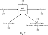
- Fig. 2 shows a schematic view of an audio processor 200 according to an embodiment of the present invention.
- Fig. 2 shows a basic implementation of the proposed audio processing.
- the audio processor 200 receives an audio input 210.
- the audio input 210 can, for example, be one or more audio channels.
- the audio processor 200 processes the audio input and outputs the audio input as an audio output 220.
- the processing of the audio processor 200 is determined by the listener positioning 230 and loudspeaker characteristics (for example, the loudspeaker positioning 240 and the loudspeaker radiation characteristics 250).
- the audio processor 200 receives as incoming information the listener positioning 230, the loudspeaker positioning 240 and the loudspeaker radiation characteristics 250 and bases the processing of the audio input 210 on this information to get the audio output 220.
- the audio processor 200 for example, generates a set of one or more parameters and modifies the audio input 210 with this set of one or more parameters to generate a new optimized audio output 220.
- the audio processor 200 optimizes the audio input 210 based on the listener positioning 230, the loudspeaker positioning 240 and the loudspeaker radiation characteristics 250.
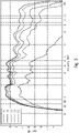
- Fig. 3 shows a diagram of the loudspeaker's frequency response.
- Fig. 3 shows on the abscissa the frequency in kHz and on the ordinate the gain in dB.
- Fig. 3 shows an example of frequency responses of a loudspeaker at different directions (relative to on-axis forward direction). The more the direction deviates from on-axis, the more high frequencies are attenuated. The frequency responses are shown for different angles.
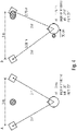
- Fig. 4 shows that without the proposed processing the quality of the audio reproduction highly varies with the change of position of a listener, for example, when the listener is moving.
- the evoked spatial auditory image is unstable for changes of the listening position away from the sweet-spot.
- the stereophonic image collapses into the closest loudspeaker.
- Fig. 4 exemplifies this collapse using the example of a single phantom source (grey disc) that is reproduced using a standard two-channel stereophonic playback setup.
- the spatial image collapses and sound is perceived as coming mainly/only from the right loudspeaker. This is undesired.
- the listener's position can be tracked and thus, for example, the gain and delay can be adjusted to compensate deviations from the optimal listening position. Accordingly, it can be seen that the present invention clearly outperforms conventional solutions.
- aspects have been described in the context of an apparatus, it is clear that these aspects also represent a description of the corresponding method, where a block or device corresponds to a method step or a feature of a method step. Analogously, aspects described in the context of a method step also represent a description of a corresponding block or item or feature of a corresponding apparatus.
- Some or all of the method steps may be executed by (or using) a hardware apparatus like, for example, a microprocessor, a programmable computer or an electronic circuit. In some embodiments, one or more of the most important method steps may be executed by such an apparatus.
- embodiments of the invention can be implemented in hardware or in software.
- the implementation can be performed using a digital storage medium, for example, a floppy disk, a DVD, a Blu-Ray, a CD, a ROM, a PROM, an EPROM, an EEPROM or a FLASH memory, having electronically readable control signals stored thereon, which cooperate (or are capable of cooperating) with a programmable computer system such that the respective method is performed. Therefore, the digital storage medium may be computer readable.
- Some embodiments according to the invention comprise a data carrier having electronically readable control signals, which are capable of cooperating with a programmable computer system, such that one of the methods described herein is performed.
- embodiments of the present invention can be implemented as a computer program product with a program code, the program code being operative for performing one of the methods when the computer program product runs on a computer.
- the program code may, for example, be stored on a machine readable carrier.
- inventions comprise the computer program for performing one of the methods described herein, stored on a machine readable carrier.
- an embodiment of the inventive method is, therefore, a computer program having a program code for performing one of the methods described herein, when the computer program runs on a computer.
- a further embodiment of the inventive methods is, therefore, a data carrier (or a digital storage medium, or a computer-readable medium) comprising, recorded thereon, the computer program for performing one of the methods described herein.
- the data carrier, the digital storage medium or the recorded medium are typically tangible and/or non-transitionary.
- a further embodiment of the inventive method is, therefore, a data stream or a sequence of signals representing the computer program for performing one of the methods described herein.
- the data stream or the sequence of signals may, for example, be configured to be transferred via a data communication connection, for example, via the Internet.
- a further embodiment comprises a processing means, for example, a computer, or a programmable logic device, configured to or adapted to perform one of the methods described herein.
- a processing means for example, a computer, or a programmable logic device, configured to or adapted to perform one of the methods described herein.
- a further embodiment comprises a computer having installed thereon the computer program for performing one of the methods described herein.
- a further embodiment according to the invention comprises an apparatus or a system configured to transfer (for example, electronically or optically) a computer program for performing one of the methods described herein to a receiver.
- the receiver may, for example, be a computer, a mobile device, a memory device or the like.
- the apparatus or system may, for example, comprise a file server for transferring the computer program to the receiver.
- a programmable logic device for example, a field programmable gate array
- a field programmable gate array may cooperate with a microprocessor in order to perform one of the methods described herein.
- the methods are preferably performed by any hardware apparatus.
- the apparatus described herein may be implemented using a hardware apparatus, or using a computer, or using a combination of a hardware apparatus and a computer.
- the apparatus described herein, or any components of the apparatus described herein, may be implemented at least partially in hardware and/or in software.
- the methods described herein may be performed using a hardware apparatus, or using a computer, or using a combination of a hardware apparatus and a computer.
Landscapes
- Physics & Mathematics (AREA)
- Engineering & Computer Science (AREA)
- Acoustics & Sound (AREA)
- Signal Processing (AREA)
- Health & Medical Sciences (AREA)
- General Health & Medical Sciences (AREA)
- Otolaryngology (AREA)
- Stereophonic System (AREA)
- Stereo-Broadcasting Methods (AREA)
- Circuit For Audible Band Transducer (AREA)
Claims (15)
- Processeur audio (100, 200) configuré pour générer, pour chacun d'un ensemble (110) d'un ou plusieurs haut-parleurs (112, 114), un ensemble d'un ou plusieurs paramètres (120, 122) qui déterminent une dérivation d'un signal de haut-parleur (164, 166) à reproduire par un haut-parleur respectif (112, 114) à partir d'un signal audio (130, 210), sur base d'une position d'auditeur (152, 172, 230) et d'un positionnement de haut-parleur (154, 240) de l'ensemble (110) d'un ou plusieurs haut-parleurs (112, 114), dans lequel le positionnement de haut-parleur (154, 240) est défini par la position et l'orientation des haut-parleurs (112, 114);dans lequel le processeur audio (100, 200) est configuré pour baser la génération de l'ensemble d'un ou plusieurs paramètres (120, 122) pour le haut-parleur respectif (112, 114) de l'ensemble (110) d'un ou plusieurs haut-parleurs (112, 114) sur une caractéristique de haut-parleur (156, 250) d'au moins un de l'ensemble (110) d'un ou plusieurs haut-parleurs (112, 114), dans lequel la caractéristique de haut-parleur (156, 250) représente une réponse en fréquence dépendante de l'angle d'émission d'une caractéristique d'émission de l'au moins un de l'ensemble d'un ou plusieurs haut-parleurs, etdans lequel le processeur audio (100, 200) est configuré pour régler chaque ensemble d'un ou plusieurs paramètres (120, 122) séparément en fonction d'un angle selon lequel se trouve la position de l'auditeur (152, 172, 230) par rapport à une direction en avant sur l'axe du haut-parleur respectif (112, 114) de l'ensemble (110) d'un ou plusieurs haut-parleurs (112, 114),dans lequel le processeur audio (100, 200) est configuré de sorte que l'ensemble d'un ou plusieurs paramètres (120, 122) pour le haut-parleur respectif (110, 112, 114) soit ajusté de sorte que le signal de haut-parleur (164, 166) du haut-parleur respectif (112, 114) soit dérivé du signal audio (130, 210) à reproduire en filtrant de manière spectrale par une fonction de transfert qui compense une déviation d'une réponse en fréquence d'une caractéristique d'émission (156, 250) du haut-parleur respectif (110, 112, 114) dans une direction pointant de la position de haut-parleur (154, 240) du haut-parleur respectif (110, 112, 114) vers la position d'auditeur (152, 172, 230) à partir de la réponse en fréquence de la caractéristique d'émission (156, 250) du haut-parleur respectif (110, 112, 114) dans la direction en avant sur l'axe.
- Processeur audio (100, 200) selon la revendication 1, dans lequel, pour chacun de l'ensemble (110) d'un ou plusieurs haut-parleurs (112, 114), l'ensemble d'un ou plusieurs paramètres (120, 122) détermine la dérivation du signal de haut-parleur (164, 166) à reproduire en modifiant le signal audio (130, 210) par une modification de retard, une modification d'amplitude et/ou un filtrage spectral.
- Processeur audio (100, 200) selon l'une des revendications 1 à 2, dans lequel le processeur audio (100, 200) est configuré pour effectuer la génération de l'ensemble d'un ou plusieurs paramètres (120, 122) pour l'ensemble (110) d'un ou plusieurs haut-parleurs (112, 114), pour modifier le signal de haut-parleur (164, 166), de sorte que les réponses en fréquence soient ajustées pour compenser les variations de réponse en fréquence dues aux différents angles selon lesquels les différents haut-parleurs (112, 114) émettent du son (160, 162, 220) vers la position d'auditeur (152, 172, 230).
- Processeur audio (100, 200) selon l'une des revendications 1 à 3, dans lequel le processeur audio (100, 200) est par ailleurs configuré pour effectuer la génération de l'ensemble d'un ou plusieurs paramètres (120, 122) pour l'ensemble (110) d'un ou plusieurs haut-parleurs (112, 114) de sorte que les niveaux soient ajustés pour compenser les différences de niveau dues aux différences de distance entre les différents haut-parleurs (112, 114) et la position d'auditeur (152, 172, 230),pour effectuer la génération de l'ensemble d'un ou plusieurs paramètres (120, 122) pour l'ensemble (110) d'un ou plusieurs haut-parleurs (112, 114) de sorte que les retards soient ajustés pour compenser les différences de retard dues aux différences de distance entre les différents haut-parleurs (112, 114) et la position d'auditeur (152, 172, 230), et/oupour effectuer la génération de l'ensemble d'un ou plusieurs paramètres (120, 122) pour l'ensemble (110) d'un ou plusieurs haut-parleurs (112, 114) de sorte que soit appliqué un repositionnement d'éléments dans un mélange de sons pour rendre une image sonore à un positionnement souhaité.
- Processeur audio (100, 200) selon la revendication 1 ou la revendication 4, dans lequel la position d'auditeur (152, 172, 230) définit une position horizontale de l'auditeur; et/oula position de la tête d'un auditeur en trois dimensions; et/oula position et l'orientation de la tête d'un auditeur.
- Processeur audio (100, 200) selon l'une des revendications 1 à 5, configuré pour recevoir la position d'auditeur (152, 172, 230) en temps réel, et pour ajuster les réponses de retard, de niveau et en fréquence en temps réel.
- Processeur audio (100, 200) selon l'une des revendications 1 à 6, dans lequel le processeur audio (100, 200) supporte plusieurs positions d'auditeur prédéfinies (152, 172, 230), dans lequel le processeur audio (100, 200) est configuré pour effectuer la génération de l'ensemble d'un ou plusieurs paramètres (120, 122) pour l'ensemble (110) d'un ou plusieurs haut-parleurs (112, 114) en pré-calculant l'ensemble d'un ou plusieurs paramètres (120, 122) pour l'ensemble (110) d'un ou plusieurs haut-parleurs (112, 114) pour chacune des multiples positions d'auditeur prédéfinies (152, 172, 230).
- Processeur audio (100, 200) selon l'une des revendications 1 à 7, configuré pour effectuer la génération sur base d'un ensemble de plus d'une position d'auditeur.
- Processeur audio (100, 200) selon l'une des revendications 1 à 8, dans lequel l'ensemble d'un ou plusieurs paramètres (120, 122) définit un filtre de dégradé.
- Processeur audio (100, 200) selon l'une des revendications 1 à 9, configuré pour effectuer la générationpour chaque haut-parleur séparément en fonction de la position d'auditeur par rapport au haut-parleur respectif, ouen fonction des différences d'un emplacement relatif de la position d'auditeur par rapport aux haut-parleurs.
- Processeur audio (100, 200) selon l'une des revendications 1 à 10, dans lequel l'ensemble (110) d'un ou plusieurs haut-parleurs (112, 114) comprend une configuration de haut-parleurs 3D, une configuration de haut-parleurs hérités, un réseau de haut-parleurs, une barre de son et/ou des haut-parleurs virtuels.
- Processeur audio (100, 200) selon l'une des revendications 1 à 11, dans lequel les caractéristiques de haut-parleur sont mesurées ou prises de bases de données ou approximées par des modèles simplifiés.
- Système comprenant le processeur audio (100, 200) selon l'une des revendications 1 à 12, l'ensemble (110) d'un ou plusieurs haut-parleurs (112, 114) et, pour chaque ensemble (110) d'un ou plusieurs haut-parleurs (112, 114), un modificateur de signal (140, 142) destiné à dériver le signal de haut-parleur (164, 166) à reproduire par le haut-parleur respectif (112, 114) d'un signal audio (130, 210) à l'aide d'un ensemble d'un ou plusieurs paramètres (120, 122) générés pour le haut-parleur respectif (112, 114) par le processeur audio (100, 200).
- Procédé permettant de faire fonctionner un processeur audio (100, 200), dans lequel est généré un ensemble d'un ou plusieurs paramètres (120, 122), pour chacun d'un ensemble (110) d'un ou plusieurs haut-parleurs (112, 114), qui déterminent une dérivation d'un signal de haut-parleur (164, 166) à reproduire par un haut-parleur respectif (112, 114) à partir d'un signal audio (130, 210), sur base d'une position d'auditeur (152, 172, 230) et d'un positionnement de haut-parleur (154, 240) de l'ensemble (110) d'un ou plusieurs haut-parleurs (112, 114), dans lequel le positionnement de haut-parleur (154, 240) est défini par la position et l'orientation des haut-parleurs (112, 114);dans lequel le processeur audio (100, 200) base la génération de l'ensemble d'un ou plusieurs paramètres (120, 122) du haut-parleur respectif (112, 114) de l'ensemble (110) d'un ou plusieurs haut-parleurs (112, 114) sur une caractéristique de haut-parleur (156, 250) d'au moins un de l'ensemble (110) d'un ou plusieurs haut-parleurs (112, 114), dans lequel la caractéristique de haut-parleur (156, 250) représente une réponse en fréquence dépendante de l'angle d'émission d'une caractéristique d'émission de l'au moins un de l'ensemble d'un ou plusieurs haut-parleurs, etdans lequel le processeur audio (100, 200) règle chaque ensemble d'un ou plusieurs paramètres (120, 122) séparément en fonction d'un angle selon lequel se trouve la position d'auditeur (152, 172, 230) par rapport à une direction en avant sur l'axe du haut-parleur respectif (112, 114) de l'ensemble (110) d'un ou plusieurs haut-parleurs (112, 114),dans lequel l'ensemble d'un ou plusieurs paramètres (120, 122) pour le haut-parleur respectif (110, 112, 114) est ajusté de sorte que le signal de haut-parleur (164, 166) du haut-parleur respectif (112, 114) soit dérivé du signal audio (130, 210) à reproduire en filtrant de manière spectrale par une fonction de transfert qui compense une déviation d'une réponse en fréquence d'une caractéristique d'émission (156, 250) du haut-parleur respectif (110, 112, 114) dans une direction pointant de la position de haut-parleur (154, 240) du haut-parleur respectif (110, 112, 114) vers la position d'auditeur (152, 172, 230) à partir de la réponse en fréquence de la caractéristique d'émission (156, 250) du haut-parleur respectif (110, 112, 114) dans la direction en avant sur l'axe.
- Programme d'ordinateur présentant un code de programme pour réaliser, lorsqu'il est exécuté sur un ordinateur, un procédé selon la revendication 14 à l'aide d'un processeur audio selon la revendication 1.
Applications Claiming Priority (2)
| Application Number | Priority Date | Filing Date | Title |
|---|---|---|---|
| EP17169333 | 2017-05-03 | ||
| PCT/EP2018/000114 WO2018202324A1 (fr) | 2017-05-03 | 2018-03-23 | Processeur audio, système, procédé et programme informatique pour rendu audio |
Publications (2)
| Publication Number | Publication Date |
|---|---|
| EP3619921A1 EP3619921A1 (fr) | 2020-03-11 |
| EP3619921B1 true EP3619921B1 (fr) | 2022-11-02 |
Family
ID=58709221
Family Applications (1)
| Application Number | Title | Priority Date | Filing Date |
|---|---|---|---|
| EP18714682.4A Active EP3619921B1 (fr) | 2017-05-03 | 2018-03-23 | Processeur audio, système, procédé ainsi que programme d'ordinateur pour la reproduction audio |
Country Status (14)
| Country | Link |
|---|---|
| US (1) | US11032646B2 (fr) |
| EP (1) | EP3619921B1 (fr) |
| JP (1) | JP7019723B2 (fr) |
| KR (1) | KR102320279B1 (fr) |
| CN (1) | CN110771182B (fr) |
| BR (1) | BR112019023170A2 (fr) |
| CA (1) | CA3061809C (fr) |
| ES (1) | ES2934801T3 (fr) |
| FI (1) | FI3619921T3 (fr) |
| MX (1) | MX2019013056A (fr) |
| PL (1) | PL3619921T3 (fr) |
| PT (1) | PT3619921T (fr) |
| RU (1) | RU2734231C1 (fr) |
| WO (1) | WO2018202324A1 (fr) |
Families Citing this family (18)
| Publication number | Priority date | Publication date | Assignee | Title |
|---|---|---|---|---|
| WO2020030304A1 (fr) | 2018-08-09 | 2020-02-13 | Fraunhofer-Gesellschaft zur Förderung der angewandten Forschung e.V. | Processeur audio et procédé prenant en compte des obstacles acoustiques et fournissant des signaux de haut-parleur |
| EP4005233A1 (fr) | 2019-07-30 | 2022-06-01 | Dolby Laboratories Licensing Corporation | Lecture audio spatiale adaptable |
| US11659332B2 (en) | 2019-07-30 | 2023-05-23 | Dolby Laboratories Licensing Corporation | Estimating user location in a system including smart audio devices |
| US11968268B2 (en) | 2019-07-30 | 2024-04-23 | Dolby Laboratories Licensing Corporation | Coordination of audio devices |
| WO2021021750A1 (fr) | 2019-07-30 | 2021-02-04 | Dolby Laboratories Licensing Corporation | Traitement de dynamique en travers de dispositifs ayant différentes capacités de lecture |
| CN114175686B (zh) | 2019-07-30 | 2024-03-15 | 杜比实验室特许公司 | 音频处理方法和系统及相关非暂时性介质 |
| CN114207715A (zh) | 2019-07-30 | 2022-03-18 | 杜比实验室特许公司 | 用于分布式音频设备的声学回声消除控制 |
| US11140509B2 (en) * | 2019-08-27 | 2021-10-05 | Daniel P. Anagnos | Head-tracking methodology for headphones and headsets |
| TWI757763B (zh) * | 2020-06-10 | 2022-03-11 | 宏碁股份有限公司 | 電子裝置及其雙聲道音場平衡方法 |
| CN113923561A (zh) * | 2020-07-08 | 2022-01-11 | 阿里巴巴集团控股有限公司 | 一种智能音箱音效调整方法和装置 |
| CN114582356A (zh) * | 2020-11-30 | 2022-06-03 | 华为技术有限公司 | 一种音频编解码方法和装置 |
| US12003955B2 (en) | 2020-12-01 | 2024-06-04 | Samsung Electronics Co., Ltd. | Display apparatus and control method thereof |
| WO2022119989A1 (fr) * | 2020-12-03 | 2022-06-09 | Dolby Laboratories Licensing Corporation | Multiplexage d'audio spatial dans le domaine fréquentiel pour de multiples points idéaux d'auditeur |
| WO2022119988A1 (fr) * | 2020-12-03 | 2022-06-09 | Dolby Laboratories Licensing Corporation | Multiplexage dans le domaine fréquentiel de l'audio spatial pour de multiples points idéaux d'écoute |
| US20220345844A1 (en) * | 2021-04-23 | 2022-10-27 | Samsung Electronics Co., Ltd. | Electronic apparatus for audio signal processing and operating method thereof |
| KR20220146165A (ko) * | 2021-04-23 | 2022-11-01 | 삼성전자주식회사 | 오디오 신호 처리를 위한 전자 장치 및 그 동작 방법 |
| US20240015459A1 (en) * | 2022-07-07 | 2024-01-11 | Harman International Industries, Incorporated | Motion detection of speaker units |
| CN117651238B (zh) * | 2024-01-30 | 2024-05-31 | 科大讯飞(苏州)科技有限公司 | 音频播放方法、音频补偿系数的确定方法和汽车 |
Citations (1)
| Publication number | Priority date | Publication date | Assignee | Title |
|---|---|---|---|---|
| US20080273713A1 (en) * | 2007-05-04 | 2008-11-06 | Klaus Hartung | System and method for directionally radiating sound |
Family Cites Families (16)
| Publication number | Priority date | Publication date | Assignee | Title |
|---|---|---|---|---|
| KR0185021B1 (ko) | 1996-11-20 | 1999-04-15 | 한국전기통신공사 | 다채널 음향시스템의 자동 조절장치 및 그 방법 |
| US6798889B1 (en) * | 1999-11-12 | 2004-09-28 | Creative Technology Ltd. | Method and apparatus for multi-channel sound system calibration |
| JP4264686B2 (ja) | 2000-09-14 | 2009-05-20 | ソニー株式会社 | 車載用音響再生装置 |
| US20060088174A1 (en) * | 2004-10-26 | 2006-04-27 | Deleeuw William C | System and method for optimizing media center audio through microphones embedded in a remote control |
| TWI279782B (en) | 2005-09-26 | 2007-04-21 | Sunplus Technology Co Ltd | Block code error correction system |
| JP5254951B2 (ja) * | 2006-03-31 | 2013-08-07 | コーニンクレッカ フィリップス エレクトロニクス エヌ ヴィ | データ処理装置及び方法 |
| US20100260360A1 (en) * | 2009-04-14 | 2010-10-14 | Strubwerks Llc | Systems, methods, and apparatus for calibrating speakers for three-dimensional acoustical reproduction |
| CN102696244B (zh) * | 2009-10-05 | 2015-01-07 | 哈曼国际工业有限公司 | 具有音频通道补偿的多通道音频系统 |
| KR101387195B1 (ko) * | 2009-10-05 | 2014-04-21 | 하만인터내셔날인더스트리스인코포레이티드 | 오디오 신호의 공간 추출 시스템 |
| US9036841B2 (en) | 2010-03-18 | 2015-05-19 | Koninklijke Philips N.V. | Speaker system and method of operation therefor |
| US20120148075A1 (en) * | 2010-12-08 | 2012-06-14 | Creative Technology Ltd | Method for optimizing reproduction of audio signals from an apparatus for audio reproduction |
| US9510126B2 (en) * | 2012-01-11 | 2016-11-29 | Sony Corporation | Sound field control device, sound field control method, program, sound control system and server |
| US10725726B2 (en) | 2012-12-20 | 2020-07-28 | Strubwerks, LLC | Systems, methods, and apparatus for assigning three-dimensional spatial data to sounds and audio files |
| EP2830332A3 (fr) * | 2013-07-22 | 2015-03-11 | Fraunhofer-Gesellschaft zur Förderung der angewandten Forschung e.V. | Procédé, unité de traitement de signal et programme informatique permettant de mapper une pluralité de canaux d'entrée d'une configuration de canal d'entrée vers des canaux de sortie d'une configuration de canal de sortie |
| EP2930957B1 (fr) * | 2014-04-07 | 2021-02-17 | Harman Becker Automotive Systems GmbH | Génération d'un champ d'ondes sonores |
| JP2015206989A (ja) * | 2014-04-23 | 2015-11-19 | ソニー株式会社 | 情報処理装置、情報処理方法及びプログラム |
-
2018
- 2018-03-23 KR KR1020197035649A patent/KR102320279B1/ko active IP Right Grant
- 2018-03-23 CN CN201880029521.6A patent/CN110771182B/zh active Active
- 2018-03-23 FI FIEP18714682.4T patent/FI3619921T3/fi active
- 2018-03-23 PT PT187146824T patent/PT3619921T/pt unknown
- 2018-03-23 CA CA3061809A patent/CA3061809C/fr active Active
- 2018-03-23 EP EP18714682.4A patent/EP3619921B1/fr active Active
- 2018-03-23 RU RU2019139033A patent/RU2734231C1/ru active
- 2018-03-23 WO PCT/EP2018/000114 patent/WO2018202324A1/fr active Search and Examination
- 2018-03-23 JP JP2019560398A patent/JP7019723B2/ja active Active
- 2018-03-23 BR BR112019023170-6A patent/BR112019023170A2/pt active Search and Examination
- 2018-03-23 PL PL18714682.4T patent/PL3619921T3/pl unknown
- 2018-03-23 MX MX2019013056A patent/MX2019013056A/es unknown
- 2018-03-23 ES ES18714682T patent/ES2934801T3/es active Active
-
2019
- 2019-10-25 US US16/664,520 patent/US11032646B2/en active Active
Patent Citations (1)
| Publication number | Priority date | Publication date | Assignee | Title |
|---|---|---|---|---|
| US20080273713A1 (en) * | 2007-05-04 | 2008-11-06 | Klaus Hartung | System and method for directionally radiating sound |
Also Published As
| Publication number | Publication date |
|---|---|
| CN110771182B (zh) | 2021-11-05 |
| PT3619921T (pt) | 2022-12-27 |
| EP3619921A1 (fr) | 2020-03-11 |
| US11032646B2 (en) | 2021-06-08 |
| ES2934801T3 (es) | 2023-02-27 |
| KR102320279B1 (ko) | 2021-11-03 |
| PL3619921T3 (pl) | 2023-03-06 |
| KR20200003159A (ko) | 2020-01-08 |
| US20200059724A1 (en) | 2020-02-20 |
| RU2734231C1 (ru) | 2020-10-13 |
| WO2018202324A1 (fr) | 2018-11-08 |
| BR112019023170A2 (pt) | 2020-06-02 |
| JP7019723B2 (ja) | 2022-02-15 |
| CA3061809C (fr) | 2022-05-03 |
| CA3061809A1 (fr) | 2018-11-08 |
| CN110771182A (zh) | 2020-02-07 |
| MX2019013056A (es) | 2020-02-07 |
| FI3619921T3 (fi) | 2023-02-22 |
| JP2020519175A (ja) | 2020-06-25 |
Similar Documents
| Publication | Publication Date | Title |
|---|---|---|
| EP3619921B1 (fr) | Processeur audio, système, procédé ainsi que programme d'ordinateur pour la reproduction audio | |
| US9648440B2 (en) | Virtual height filter for reflected sound rendering using upward firing drivers | |
| EP2806658A1 (fr) | Agencement et procédé de reproduction de données audio d'une scène acoustique | |
| US20150293655A1 (en) | Method for outputting a modified audio signal and graphical user interfaces produced by an application program | |
| US10313819B1 (en) | Phantom center image control | |
| US10945090B1 (en) | Surround sound rendering based on room acoustics | |
| US9226091B2 (en) | Acoustic surround immersion control system and method | |
| US6990210B2 (en) | System for headphone-like rear channel speaker and the method of the same | |
| US11477595B2 (en) | Audio processing device and audio processing method | |
| KR102609084B1 (ko) | 전자장치, 그 제어방법 및 기록매체 | |
| JP6512767B2 (ja) | 音響処理装置および方法、並びにプログラム | |
| US6983054B2 (en) | Means for compensating rear sound effect | |
| EP4383757A1 (fr) | Compensation de positionnement de haut-parleur et d'auditeur adaptatifs | |
| EP4369740A1 (fr) | Amélioration adaptative de la largeur d'image sonore | |
| US20220038838A1 (en) | Lower layer reproduction | |
| Simon Galvez et al. | Listener tracking stereo for object based audio reproduction |
Legal Events
| Date | Code | Title | Description |
|---|---|---|---|
| STAA | Information on the status of an ep patent application or granted ep patent |
Free format text: STATUS: UNKNOWN |
|
| STAA | Information on the status of an ep patent application or granted ep patent |
Free format text: STATUS: THE INTERNATIONAL PUBLICATION HAS BEEN MADE |
|
| PUAI | Public reference made under article 153(3) epc to a published international application that has entered the european phase |
Free format text: ORIGINAL CODE: 0009012 |
|
| STAA | Information on the status of an ep patent application or granted ep patent |
Free format text: STATUS: REQUEST FOR EXAMINATION WAS MADE |
|
| 17P | Request for examination filed |
Effective date: 20191024 |
|
| AK | Designated contracting states |
Kind code of ref document: A1 Designated state(s): AL AT BE BG CH CY CZ DE DK EE ES FI FR GB GR HR HU IE IS IT LI LT LU LV MC MK MT NL NO PL PT RO RS SE SI SK SM TR |
|
| AX | Request for extension of the european patent |
Extension state: BA ME |
|
| RIN1 | Information on inventor provided before grant (corrected) |
Inventor name: WALTHER, ANDREAS Inventor name: HERRE, JURGEN Inventor name: FALLER, CHRISTOF Inventor name: KLAPP, JULIAN |
|
| DAV | Request for validation of the european patent (deleted) | ||
| DAX | Request for extension of the european patent (deleted) | ||
| STAA | Information on the status of an ep patent application or granted ep patent |
Free format text: STATUS: EXAMINATION IS IN PROGRESS |
|
| 17Q | First examination report despatched |
Effective date: 20201217 |
|
| RAP3 | Party data changed (applicant data changed or rights of an application transferred) |
Owner name: FRAUNHOFER-GESELLSCHAFT ZUR FOERDERUNG DER ANGEWANDTEN FORSCHUNG E.V. |
|
| GRAP | Despatch of communication of intention to grant a patent |
Free format text: ORIGINAL CODE: EPIDOSNIGR1 |
|
| STAA | Information on the status of an ep patent application or granted ep patent |
Free format text: STATUS: GRANT OF PATENT IS INTENDED |
|
| INTG | Intention to grant announced |
Effective date: 20220516 |
|
| GRAS | Grant fee paid |
Free format text: ORIGINAL CODE: EPIDOSNIGR3 |
|
| GRAA | (expected) grant |
Free format text: ORIGINAL CODE: 0009210 |
|
| STAA | Information on the status of an ep patent application or granted ep patent |
Free format text: STATUS: THE PATENT HAS BEEN GRANTED |
|
| AK | Designated contracting states |
Kind code of ref document: B1 Designated state(s): AL AT BE BG CH CY CZ DE DK EE ES FI FR GB GR HR HU IE IS IT LI LT LU LV MC MK MT NL NO PL PT RO RS SE SI SK SM TR |
|
| REG | Reference to a national code |
Ref country code: GB Ref legal event code: FG4D |
|
| REG | Reference to a national code |
Ref country code: CH Ref legal event code: EP Ref country code: AT Ref legal event code: REF Ref document number: 1529645 Country of ref document: AT Kind code of ref document: T Effective date: 20221115 |
|
| REG | Reference to a national code |
Ref country code: DE Ref legal event code: R096 Ref document number: 602018042526 Country of ref document: DE |
|
| REG | Reference to a national code |
Ref country code: IE Ref legal event code: FG4D |
|
| REG | Reference to a national code |
Ref country code: PT Ref legal event code: SC4A Ref document number: 3619921 Country of ref document: PT Date of ref document: 20221227 Kind code of ref document: T Free format text: AVAILABILITY OF NATIONAL TRANSLATION Effective date: 20221220 |
|
| REG | Reference to a national code |
Ref country code: NL Ref legal event code: FP |
|
| REG | Reference to a national code |
Ref country code: SE Ref legal event code: TRGR |
|
| REG | Reference to a national code |
Ref country code: LT Ref legal event code: MG9D Ref country code: ES Ref legal event code: FG2A Ref document number: 2934801 Country of ref document: ES Kind code of ref document: T3 Effective date: 20230227 |
|
| REG | Reference to a national code |
Ref country code: AT Ref legal event code: MK05 Ref document number: 1529645 Country of ref document: AT Kind code of ref document: T Effective date: 20221102 |
|
| PG25 | Lapsed in a contracting state [announced via postgrant information from national office to epo] |
Ref country code: NO Free format text: LAPSE BECAUSE OF FAILURE TO SUBMIT A TRANSLATION OF THE DESCRIPTION OR TO PAY THE FEE WITHIN THE PRESCRIBED TIME-LIMIT Effective date: 20230202 Ref country code: LT Free format text: LAPSE BECAUSE OF FAILURE TO SUBMIT A TRANSLATION OF THE DESCRIPTION OR TO PAY THE FEE WITHIN THE PRESCRIBED TIME-LIMIT Effective date: 20221102 Ref country code: AT Free format text: LAPSE BECAUSE OF FAILURE TO SUBMIT A TRANSLATION OF THE DESCRIPTION OR TO PAY THE FEE WITHIN THE PRESCRIBED TIME-LIMIT Effective date: 20221102 |
|
| PG25 | Lapsed in a contracting state [announced via postgrant information from national office to epo] |
Ref country code: RS Free format text: LAPSE BECAUSE OF FAILURE TO SUBMIT A TRANSLATION OF THE DESCRIPTION OR TO PAY THE FEE WITHIN THE PRESCRIBED TIME-LIMIT Effective date: 20221102 Ref country code: LV Free format text: LAPSE BECAUSE OF FAILURE TO SUBMIT A TRANSLATION OF THE DESCRIPTION OR TO PAY THE FEE WITHIN THE PRESCRIBED TIME-LIMIT Effective date: 20221102 Ref country code: IS Free format text: LAPSE BECAUSE OF FAILURE TO SUBMIT A TRANSLATION OF THE DESCRIPTION OR TO PAY THE FEE WITHIN THE PRESCRIBED TIME-LIMIT Effective date: 20230302 Ref country code: HR Free format text: LAPSE BECAUSE OF FAILURE TO SUBMIT A TRANSLATION OF THE DESCRIPTION OR TO PAY THE FEE WITHIN THE PRESCRIBED TIME-LIMIT Effective date: 20221102 Ref country code: GR Free format text: LAPSE BECAUSE OF FAILURE TO SUBMIT A TRANSLATION OF THE DESCRIPTION OR TO PAY THE FEE WITHIN THE PRESCRIBED TIME-LIMIT Effective date: 20230203 |
|
| P01 | Opt-out of the competence of the unified patent court (upc) registered |
Effective date: 20230517 |
|
| PG25 | Lapsed in a contracting state [announced via postgrant information from national office to epo] |
Ref country code: SM Free format text: LAPSE BECAUSE OF FAILURE TO SUBMIT A TRANSLATION OF THE DESCRIPTION OR TO PAY THE FEE WITHIN THE PRESCRIBED TIME-LIMIT Effective date: 20221102 Ref country code: RO Free format text: LAPSE BECAUSE OF FAILURE TO SUBMIT A TRANSLATION OF THE DESCRIPTION OR TO PAY THE FEE WITHIN THE PRESCRIBED TIME-LIMIT Effective date: 20221102 Ref country code: EE Free format text: LAPSE BECAUSE OF FAILURE TO SUBMIT A TRANSLATION OF THE DESCRIPTION OR TO PAY THE FEE WITHIN THE PRESCRIBED TIME-LIMIT Effective date: 20221102 Ref country code: DK Free format text: LAPSE BECAUSE OF FAILURE TO SUBMIT A TRANSLATION OF THE DESCRIPTION OR TO PAY THE FEE WITHIN THE PRESCRIBED TIME-LIMIT Effective date: 20221102 Ref country code: CZ Free format text: LAPSE BECAUSE OF FAILURE TO SUBMIT A TRANSLATION OF THE DESCRIPTION OR TO PAY THE FEE WITHIN THE PRESCRIBED TIME-LIMIT Effective date: 20221102 |
|
| REG | Reference to a national code |
Ref country code: DE Ref legal event code: R097 Ref document number: 602018042526 Country of ref document: DE |
|
| PG25 | Lapsed in a contracting state [announced via postgrant information from national office to epo] |
Ref country code: SK Free format text: LAPSE BECAUSE OF FAILURE TO SUBMIT A TRANSLATION OF THE DESCRIPTION OR TO PAY THE FEE WITHIN THE PRESCRIBED TIME-LIMIT Effective date: 20221102 Ref country code: AL Free format text: LAPSE BECAUSE OF FAILURE TO SUBMIT A TRANSLATION OF THE DESCRIPTION OR TO PAY THE FEE WITHIN THE PRESCRIBED TIME-LIMIT Effective date: 20221102 |
|
| PLBE | No opposition filed within time limit |
Free format text: ORIGINAL CODE: 0009261 |
|
| STAA | Information on the status of an ep patent application or granted ep patent |
Free format text: STATUS: NO OPPOSITION FILED WITHIN TIME LIMIT |
|
| 26N | No opposition filed |
Effective date: 20230803 |
|
| PG25 | Lapsed in a contracting state [announced via postgrant information from national office to epo] |
Ref country code: MC Free format text: LAPSE BECAUSE OF FAILURE TO SUBMIT A TRANSLATION OF THE DESCRIPTION OR TO PAY THE FEE WITHIN THE PRESCRIBED TIME-LIMIT Effective date: 20221102 |
|
| REG | Reference to a national code |
Ref country code: CH Ref legal event code: PL |
|
| PG25 | Lapsed in a contracting state [announced via postgrant information from national office to epo] |
Ref country code: SI Free format text: LAPSE BECAUSE OF FAILURE TO SUBMIT A TRANSLATION OF THE DESCRIPTION OR TO PAY THE FEE WITHIN THE PRESCRIBED TIME-LIMIT Effective date: 20221102 |
|
| PG25 | Lapsed in a contracting state [announced via postgrant information from national office to epo] |
Ref country code: LU Free format text: LAPSE BECAUSE OF NON-PAYMENT OF DUE FEES Effective date: 20230323 |
|
| REG | Reference to a national code |
Ref country code: IE Ref legal event code: MM4A |
|
| PG25 | Lapsed in a contracting state [announced via postgrant information from national office to epo] |
Ref country code: LI Free format text: LAPSE BECAUSE OF NON-PAYMENT OF DUE FEES Effective date: 20230331 Ref country code: IE Free format text: LAPSE BECAUSE OF NON-PAYMENT OF DUE FEES Effective date: 20230323 Ref country code: CH Free format text: LAPSE BECAUSE OF NON-PAYMENT OF DUE FEES Effective date: 20230331 |
|
| PGFP | Annual fee paid to national office [announced via postgrant information from national office to epo] |
Ref country code: NL Payment date: 20240320 Year of fee payment: 7 |
|
| PGFP | Annual fee paid to national office [announced via postgrant information from national office to epo] |
Ref country code: FI Payment date: 20240319 Year of fee payment: 7 Ref country code: DE Payment date: 20240321 Year of fee payment: 7 Ref country code: PT Payment date: 20240313 Year of fee payment: 7 Ref country code: GB Payment date: 20240322 Year of fee payment: 7 |
|
| PGFP | Annual fee paid to national office [announced via postgrant information from national office to epo] |
Ref country code: TR Payment date: 20240312 Year of fee payment: 7 Ref country code: SE Payment date: 20240321 Year of fee payment: 7 Ref country code: PL Payment date: 20240308 Year of fee payment: 7 Ref country code: IT Payment date: 20240329 Year of fee payment: 7 Ref country code: FR Payment date: 20240319 Year of fee payment: 7 Ref country code: BE Payment date: 20240320 Year of fee payment: 7 |
|
| PGFP | Annual fee paid to national office [announced via postgrant information from national office to epo] |
Ref country code: ES Payment date: 20240417 Year of fee payment: 7 |