EP3619855B1 - Methods, systems, and apparatus for transmitting uplink control information - Google Patents
Methods, systems, and apparatus for transmitting uplink control information Download PDFInfo
- Publication number
- EP3619855B1 EP3619855B1 EP18725994.0A EP18725994A EP3619855B1 EP 3619855 B1 EP3619855 B1 EP 3619855B1 EP 18725994 A EP18725994 A EP 18725994A EP 3619855 B1 EP3619855 B1 EP 3619855B1
- Authority
- EP
- European Patent Office
- Prior art keywords
- pucch
- wtru
- ack
- nack
- information
- Prior art date
- Legal status (The legal status is an assumption and is not a legal conclusion. Google has not performed a legal analysis and makes no representation as to the accuracy of the status listed.)
- Active
Links
Images


Classifications
-
- H—ELECTRICITY
- H04—ELECTRIC COMMUNICATION TECHNIQUE
- H04L—TRANSMISSION OF DIGITAL INFORMATION, e.g. TELEGRAPHIC COMMUNICATION
- H04L1/00—Arrangements for detecting or preventing errors in the information received
- H04L1/12—Arrangements for detecting or preventing errors in the information received by using return channel
- H04L1/16—Arrangements for detecting or preventing errors in the information received by using return channel in which the return channel carries supervisory signals, e.g. repetition request signals
- H04L1/1607—Details of the supervisory signal
- H04L1/1692—Physical properties of the supervisory signal, e.g. acknowledgement by energy bursts
-
- H—ELECTRICITY
- H04—ELECTRIC COMMUNICATION TECHNIQUE
- H04L—TRANSMISSION OF DIGITAL INFORMATION, e.g. TELEGRAPHIC COMMUNICATION
- H04L1/00—Arrangements for detecting or preventing errors in the information received
- H04L1/12—Arrangements for detecting or preventing errors in the information received by using return channel
- H04L1/16—Arrangements for detecting or preventing errors in the information received by using return channel in which the return channel carries supervisory signals, e.g. repetition request signals
- H04L1/1607—Details of the supervisory signal
- H04L1/1671—Details of the supervisory signal the supervisory signal being transmitted together with control information
-
- H—ELECTRICITY
- H04—ELECTRIC COMMUNICATION TECHNIQUE
- H04L—TRANSMISSION OF DIGITAL INFORMATION, e.g. TELEGRAPHIC COMMUNICATION
- H04L1/00—Arrangements for detecting or preventing errors in the information received
- H04L1/12—Arrangements for detecting or preventing errors in the information received by using return channel
- H04L1/16—Arrangements for detecting or preventing errors in the information received by using return channel in which the return channel carries supervisory signals, e.g. repetition request signals
- H04L1/18—Automatic repetition systems, e.g. Van Duuren systems
- H04L1/1812—Hybrid protocols; Hybrid automatic repeat request [HARQ]
-
- H—ELECTRICITY
- H04—ELECTRIC COMMUNICATION TECHNIQUE
- H04L—TRANSMISSION OF DIGITAL INFORMATION, e.g. TELEGRAPHIC COMMUNICATION
- H04L1/00—Arrangements for detecting or preventing errors in the information received
- H04L1/12—Arrangements for detecting or preventing errors in the information received by using return channel
- H04L1/16—Arrangements for detecting or preventing errors in the information received by using return channel in which the return channel carries supervisory signals, e.g. repetition request signals
- H04L1/18—Automatic repetition systems, e.g. Van Duuren systems
- H04L1/1829—Arrangements specially adapted for the receiver end
- H04L1/1861—Physical mapping arrangements
-
- H—ELECTRICITY
- H04—ELECTRIC COMMUNICATION TECHNIQUE
- H04L—TRANSMISSION OF DIGITAL INFORMATION, e.g. TELEGRAPHIC COMMUNICATION
- H04L5/00—Arrangements affording multiple use of the transmission path
- H04L5/0001—Arrangements for dividing the transmission path
- H04L5/0003—Two-dimensional division
- H04L5/0005—Time-frequency
- H04L5/0007—Time-frequency the frequencies being orthogonal, e.g. OFDM(A) or DMT
-
- H—ELECTRICITY
- H04—ELECTRIC COMMUNICATION TECHNIQUE
- H04L—TRANSMISSION OF DIGITAL INFORMATION, e.g. TELEGRAPHIC COMMUNICATION
- H04L5/00—Arrangements affording multiple use of the transmission path
- H04L5/003—Arrangements for allocating sub-channels of the transmission path
- H04L5/0053—Allocation of signalling, i.e. of overhead other than pilot signals
- H04L5/0055—Physical resource allocation for ACK/NACK
-
- H—ELECTRICITY
- H04—ELECTRIC COMMUNICATION TECHNIQUE
- H04L—TRANSMISSION OF DIGITAL INFORMATION, e.g. TELEGRAPHIC COMMUNICATION
- H04L5/00—Arrangements affording multiple use of the transmission path
- H04L5/0091—Signalling for the administration of the divided path, e.g. signalling of configuration information
- H04L5/0094—Indication of how sub-channels of the path are allocated
-
- H—ELECTRICITY
- H04—ELECTRIC COMMUNICATION TECHNIQUE
- H04W—WIRELESS COMMUNICATION NETWORKS
- H04W72/00—Local resource management
- H04W72/04—Wireless resource allocation
- H04W72/044—Wireless resource allocation based on the type of the allocated resource
- H04W72/0453—Resources in frequency domain, e.g. a carrier in FDMA
-
- H—ELECTRICITY
- H04—ELECTRIC COMMUNICATION TECHNIQUE
- H04W—WIRELESS COMMUNICATION NETWORKS
- H04W72/00—Local resource management
- H04W72/20—Control channels or signalling for resource management
- H04W72/21—Control channels or signalling for resource management in the uplink direction of a wireless link, i.e. towards the network
-
- H—ELECTRICITY
- H04—ELECTRIC COMMUNICATION TECHNIQUE
- H04W—WIRELESS COMMUNICATION NETWORKS
- H04W72/00—Local resource management
- H04W72/20—Control channels or signalling for resource management
- H04W72/23—Control channels or signalling for resource management in the downlink direction of a wireless link, i.e. towards a terminal
Definitions
- Uplink control information may be transmitted in a Physical Uplink Control Channel (PUCCH).
- the PUCCH may be transmitted using a short or long duration.
- the UCI information may include a Scheduling Request (SR), which may be used to request radio resource.
- SR Scheduling Request
- the 3GPP DRAFT R1-1704466 titled "Performance evaluation on channel structure of short PUCCH for 1 or 2 bits UCI," published 2 April 2017 (2017-04-02 ) discloses sequence based uplink control information.
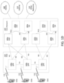
- FIG. 1A is a diagram illustrating an example communications system 100 in which one or more disclosed embodiments may be implemented.
- the communications system 100 may be a multiple access system that provides content, such as voice, data, video, messaging, broadcast, etc., to multiple wireless users.
- the communications system 100 may enable multiple wireless users to access such content through the sharing of system resources, including wireless bandwidth.
- the WTRUs 102a, 102b, 102c, 102d may be configured to transmit and/or receive wireless signals and may include a user equipment (UE), a mobile station, a fixed or mobile subscriber unit, a subscription-based unit, a pager, a cellular telephone, a personal digital assistant (PDA), a smartphone, a laptop, a netbook, a personal computer, a wireless sensor, a hotspot or Mi-Fi device, an Internet of Things (IoT) device, a watch or other wearable, a head-mounted display (HMD), a vehicle, a drone, a medical device and applications (e.g., remote surgery), an industrial device and applications (e.g., a robot and/or other wireless devices operating in an industrial and/or an automated processing chain contexts), a consumer electronics device, a device operating on commercial and/or industrial wireless networks, and the like.
- UE user equipment
- PDA personal digital assistant
- smartphone a laptop
- a netbook a personal computer
- the base station 114a and the WTRUs 102a, 102b, 102c may implement a radio technology such as NR Radio Access , which may establish the air interface 116 using New Radio (NR).
- a radio technology such as NR Radio Access , which may establish the air interface 116 using New Radio (NR).
- the base station 114a and the WTRUs 102a, 102b, 102c may implement multiple radio access technologies.
- the base station 114a and the WTRUs 102a, 102b, 102c may implement LTE radio access and NR radio access together, for instance using dual connectivity (DC) principles.
- DC dual connectivity
- the air interface utilized by WTRUs 102a, 102b, 102c may be characterized by multiple types of radio access technologies and/or transmissions sent to/from multiple types of base stations (e.g., a eNB and a gNB).
- the base station 114a and the WTRUs 102a, 102b, 102c may implement radio technologies such as IEEE 802.11 (i.e., Wireless Fidelity (WiFi), IEEE 802.16 (i.e., Worldwide Interoperability for Microwave Access (WiMAX)), CDMA2000, CDMA2000 1X, CDMA2000 EV-DO, Interim Standard 2000 (IS-2000), Interim Standard 95 (IS-95), Interim Standard 856 (IS-856), Global System for Mobile communications (GSM), Enhanced Data rates for GSM Evolution (EDGE), GSM EDGE (GERAN), and the like.
- IEEE 802.11 i.e., Wireless Fidelity (WiFi)
- IEEE 802.16 i.e., Worldwide Interoperability for Microwave Access (WiMAX)
- CDMA2000, CDMA2000 1X, CDMA2000 EV-DO Code Division Multiple Access 2000
- IS-95 Interim Standard 95
- IS-856 Interim Standard 856
- GSM Global System for
- the base station 114b in FIG. 1A may be a wireless router, Home Node B, Home eNode B, or access point, for example, and may utilize any suitable RAT for facilitating wireless connectivity in a localized area, such as a place of business, a home, a vehicle, a campus, an industrial facility, an air corridor (e.g., for use by drones), a roadway, and the like.
- the base station 114b and the WTRUs 102c, 102d may implement a radio technology such as IEEE 802.11 to establish a wireless local area network (WLAN).
- WLAN wireless local area network
- the base station 114b and the WTRUs 102c, 102d may implement a radio technology such as IEEE 802.15 to establish a wireless personal area network (WPAN).
- the base station 114b and the WTRUs 102c, 102d may utilize a cellular-based RAT (e.g., WCDMA, CDMA2000, GSM, LTE, LTE-A, LTE-A Pro, NR etc.) to establish a picocell or femtocell.
- the base station 114b may have a direct connection to the Internet 110.
- the base station 114b may not be required to access the Internet 110 via the CN 106/115.
- the RAN 104/113 may be in communication with the CN 106/115, which may be any type of network configured to provide voice, data, applications, and/or voice over internet protocol (VoIP) services to one or more of the WTRUs 102a, 102b, 102c, 102d.
- the data may have varying quality of service (QoS) requirements, such as differing throughput requirements, latency requirements, error tolerance requirements, reliability requirements, data throughput requirements, mobility requirements, and the like.
- QoS quality of service
- the CN 106/115 may provide call control, billing services, mobile location-based services, pre-paid calling, Internet connectivity, video distribution, etc., and/or perform high-level security functions, such as user authentication.
- the RAN 104/113 and/or the CN 106/115 may be in direct or indirect communication with other RANs that employ the same RAT as the RAN 104/113 or a different RAT.
- the CN 106/115 may also be in communication with another RAN (not shown) employing a GSM, UMTS, CDMA 2000, WiMAX, E-UTRA, or WiFi radio technology.
- the CN 106/115 may also serve as a gateway for the WTRUs 102a, 102b, 102c, 102d to access the PSTN 108, the Internet 110, and/or the other networks 112.
- the PSTN 108 may include circuit-switched telephone networks that provide plain old telephone service (POTS).
- POTS plain old telephone service
- the Internet 110 may include a global system of interconnected computer networks and devices that use common communication protocols, such as the transmission control protocol (TCP), user datagram protocol (UDP) and/or the internet protocol (IP) in the TCP/IP internet protocol suite.
- the networks 112 may include wired and/or wireless communications networks owned and/or operated by other service providers.
- the networks 112 may include another CN connected to one or more RANs, which may employ the same RAT as the RAN 104/113 or a different RAT.
- the WTRUs 102a, 102b, 102c, 102d in the communications system 100 may include multi-mode capabilities (e.g., the WTRUs 102a, 102b, 102c, 102d may include multiple transceivers for communicating with different wireless networks over different wireless links).
- the WTRU 102c shown in FIG. 1A may be configured to communicate with the base station 114a, which may employ a cellular-based radio technology, and with the base station 114b, which may employ an IEEE 802 radio technology.
- FIG. 1B is a system diagram illustrating an example WTRU 102.
- the WTRU 102 may include a processor 118, a transceiver 120, a transmit/receive element 122, a speaker/microphone 124, a keypad 126, a display/touchpad 128, non-removable memory 130, removable memory 132, a power source 134, a global positioning system (GPS) chipset 136, and/or other peripherals 138, among others.
- GPS global positioning system
- the processor 118 may be a general purpose processor, a special purpose processor, a conventional processor, a digital signal processor (DSP), a plurality of microprocessors, one or more microprocessors in association with a DSP core, a controller, a microcontroller, Application Specific Integrated Circuits (ASICs), Field Programmable Gate Arrays (FPGAs) circuits, any other type of integrated circuit (IC), a state machine, and the like.
- the processor 118 may perform signal coding, data processing, power control, input/output processing, and/or any other functionality that enables the WTRU 102 to operate in a wireless environment.
- the processor 118 may be coupled to the transceiver 120, which may be coupled to the transmit/receive element 122. While FIG. 1B depicts the processor 118 and the transceiver 120 as separate components, it will be appreciated that the processor 118 and the transceiver 120 may be integrated together in an electronic package or chip.
- the transmit/receive element 122 may be configured to transmit signals to, or receive signals from, a base station (e.g., the base station 114a) over the air interface 116.
- a base station e.g., the base station 114a
- the transmit/receive element 122 may be an antenna configured to transmit and/or receive RF signals.
- the transmit/receive element 122 may be an emitter/detector configured to transmit and/or receive IR, UV, or visible light signals, for example.
- the transmit/receive element 122 may be configured to transmit and/or receive both RF and light signals. It will be appreciated that the transmit/receive element 122 may be configured to transmit and/or receive any combination of wireless signals.
- the WTRU 102 may include any number of transmit/receive elements 122. More specifically, the WTRU 102 may employ MIMO technology. Thus, in one embodiment, the WTRU 102 may include two or more transmit/receive elements 122 (e.g., multiple antennas) for transmitting and receiving wireless signals over the air interface 116.
- the transceiver 120 may be configured to modulate the signals that are to be transmitted by the transmit/receive element 122 and to demodulate the signals that are received by the transmit/receive element 122.
- the WTRU 102 may have multi-mode capabilities.
- the transceiver 120 may include multiple transceivers for enabling the WTRU 102 to communicate via multiple RATs, such as NR and IEEE 802.11, for example.
- the processor 118 of the WTRU 102 may be coupled to, and may receive user input data from, the speaker/microphone 124, the keypad 126, and/or the display/touchpad 128 (e.g., a liquid crystal display (LCD) display unit or organic light-emitting diode (OLED) display unit).
- the processor 118 may also output user data to the speaker/microphone 124, the keypad 126, and/or the display/touchpad 128.
- the processor 118 may access information from, and store data in, any type of suitable memory, such as the non-removable memory 130 and/or the removable memory 132.
- the non-removable memory 130 may include random-access memory (RAM), read-only memory (ROM), a hard disk, or any other type of memory storage device.
- the removable memory 132 may include a subscriber identity module (SIM) card, a memory stick, a secure digital (SD) memory card, and the like.
- SIM subscriber identity module
- SD secure digital
- the processor 118 may access information from, and store data in, memory that is not physically located on the WTRU 102, such as on a server or a home computer (not shown).
- the processor 118 may receive power from the power source 134, and may be configured to distribute and/or control the power to the other components in the WTRU 102.
- the power source 134 may be any suitable device for powering the WTRU 102.
- the power source 134 may include one or more dry cell batteries (e.g., nickel-cadmium (NiCd), nickel-zinc (NiZn), nickel metal hydride (NiMH), lithium-ion (Li-ion), etc.), solar cells, fuel cells, and the like.
- the processor 118 may also be coupled to the GPS chipset 136, which may be configured to provide location information (e.g., longitude and latitude) regarding the current location of the WTRU 102.
- location information e.g., longitude and latitude
- the WTRU 102 may receive location information over the air interface 116 from a base station (e.g., base stations 114a, 114b) and/or determine its location based on the timing of the signals being received from two or more nearby base stations. It will be appreciated that the WTRU 102 may acquire location information by way of any suitable location-determination method while remaining consistent with an embodiment.
- the processor 118 may further be coupled to other peripherals 138, which may include one or more software and/or hardware modules that provide additional features, functionality and/or wired or wireless connectivity.
- the peripherals 138 may include an accelerometer, an e-compass, a satellite transceiver, a digital camera (for photographs and/or video), a universal serial bus (USB) port, a vibration device, a television transceiver, a hands free headset, a Bluetooth ® module, a frequency modulated (FM) radio unit, a digital music player, a media player, a video game player module, an Internet browser, a Virtual Reality and/or Augmented Reality (VR/AR) device, an activity tracker, and the like.
- FM frequency modulated
- the peripherals 138 may include one or more sensors, the sensors may be one or more of a gyroscope, an accelerometer, a hall effect sensor, a magnetometer, an orientation sensor, a proximity sensor, a temperature sensor, a time sensor; a geolocation sensor; an altimeter, a light sensor, a touch sensor, a magnetometer, a barometer, a gesture sensor, a biometric sensor, and/or a humidity sensor.
- a gyroscope an accelerometer, a hall effect sensor, a magnetometer, an orientation sensor, a proximity sensor, a temperature sensor, a time sensor; a geolocation sensor; an altimeter, a light sensor, a touch sensor, a magnetometer, a barometer, a gesture sensor, a biometric sensor, and/or a humidity sensor.
- the WTRU 102 may include a full duplex radio for which transmission and reception of some or all of the signals (e.g., associated with particular subframes for both the UL (e.g., for transmission) and downlink (e.g., for reception) may be concurrent and/or simultaneous.
- the full duplex radio may include an interference management unit to reduce and or substantially eliminate self-interference via either hardware (e.g., a choke) or signal processing via a processor (e.g., a separate processor (not shown) or via processor 118).
- the WRTU 102 may include a half-duplex radio for which transmission and reception of some or all of the signals (e.g., associated with particular subframes for either the UL (e.g., for transmission) or the downlink (e.g., for reception)).
- a half-duplex radio for which transmission and reception of some or all of the signals (e.g., associated with particular subframes for either the UL (e.g., for transmission) or the downlink (e.g., for reception)).
- FIG. 1C is a system diagram illustrating the RAN 104 and the CN 106 according to an embodiment.
- the RAN 104 may employ an E-UTRA radio technology to communicate with the WTRUs 102a, 102b, 102c over the air interface 116.
- the RAN 104 may also be in communication with the CN 106.
- the RAN 104 may include eNode-Bs 160a, 160b, 160c, though it will be appreciated that the RAN 104 may include any number of eNode-Bs while remaining consistent with an embodiment.
- the eNode-Bs 160a, 160b, 160c may each include one or more transceivers for communicating with the WTRUs 102a, 102b, 102c over the air interface 116.
- the eNode-Bs 160a, 160b, 160c may implement MIMO technology.
- the eNode-B 160a for example, may use multiple antennas to transmit wireless signals to, and/or receive wireless signals from, the WTRU 102a.
- Each of the eNode-Bs 160a, 160b, 160c may be associated with a particular cell (not shown) and may be configured to handle radio resource management decisions, handover decisions, scheduling of users in the UL and/or DL, and the like. As shown in FIG. 1C , the eNode-Bs 160a, 160b, 160c may communicate with one another over an X2 interface.
- the CN 106 may facilitate communications with other networks.
- the CN 106 may provide the WTRUs 102a, 102b, 102c with access to circuit-switched networks, such as the PSTN 108, to facilitate communications between the WTRUs 102a, 102b, 102c and traditional land-line communications devices.
- the CN 106 may include, or may communicate with, an IP gateway (e.g., an IP multimedia subsystem (IMS) server) that serves as an interface between the CN 106 and the PSTN 108.
- IMS IP multimedia subsystem
- the CN 106 may provide the WTRUs 102a, 102b, 102c with access to the other networks 112, which may include other wired and/or wireless networks that are owned and/or operated by other service providers.
- a WLAN in Infrastructure Basic Service Set (BSS) mode may have an Access Point (AP) for the BSS and one or more stations (STAs) associated with the AP.
- the AP may have an access or an interface to a Distribution System (DS) or another type of wired/wireless network that carries traffic in to and/or out of the BSS.
- Traffic to STAs that originates from outside the BSS may arrive through the AP and may be delivered to the STAs.
- Traffic originating from STAs to destinations outside the BSS may be sent to the AP to be delivered to respective destinations.
- Traffic between STAs within the BSS may be sent through the AP, for example, where the source STA may send traffic to the AP and the AP may deliver the traffic to the destination STA.
- the traffic between STAs within a BSS may be considered and/or referred to as peer-to-peer traffic.
- the peer-to-peer traffic may be sent between (e.g., directly between) the source and destination STAs with a direct link setup (DLS).
- the DLS may use an 802.11e DLS or an 802.11z tunneled DLS (TDLS).
- a WLAN using an Independent BSS (IBSS) mode may not have an AP, and the STAs (e.g., all of the STAs) within or using the IBSS may communicate directly with each other.
- the IBSS mode of communication may sometimes be referred to herein as an "ad-hoc" mode of communication.
- the AP may transmit a beacon on a fixed channel, such as a primary channel.
- the primary channel may be a fixed width (e.g., 20 MHz wide bandwidth) or a dynamically set width via signaling.
- the primary channel may be the operating channel of the BSS and may be used by the STAs to establish a connection with the AP.
- Carrier Sense Multiple Access with Collision Avoidance (CSMA/CA) may be implemented, for example in in 802.11 systems.
- the STAs e.g., every STA, including the AP, may sense the primary channel. If the primary channel is sensed/detected and/or determined to be busy by a particular STA, the particular STA may back off.
- One STA (e.g., only one station) may transmit at any given time in a given BSS.
- HT STAs may use a 40 MHz wide channel for communication, for example, via a combination of the primary 20 MHz channel with an adjacent or nonadjacent 20 MHz channel to form a 40 MHz wide channel.
- VHT STAs may support 20MHz, 40 MHz, 80 MHz, and/or 160 MHz wide channels.
- the 40 MHz, and/or 80 MHz, channels may be formed by combining contiguous 20 MHz channels.
- a 160 MHz channel may be formed by combining 8 contiguous 20 MHz channels, or by combining two non-contiguous 80 MHz channels, which may be referred to as an 80+80 configuration.
- the data, after channel encoding may be passed through a segment parser that may divide the data into two streams.
- Inverse Fast Fourier Transform (IFFT) processing, and time domain processing may be done on each stream separately.
- IFFT Inverse Fast Fourier Transform
- MTC devices may have certain capabilities, for example, limited capabilities including support for (e.g., only support for) certain and/or limited bandwidths.
- the MTC devices may include a battery with a battery life above a threshold (e.g., to maintain a very long battery life).
- WLAN systems which may support multiple channels, and channel bandwidths, such as 802.11n, 802.11ac, 802.11af, and 802.11ah, include a channel which may be designated as the primary channel.
- the primary channel may have a bandwidth equal to the largest common operating bandwidth supported by all STAs in the BSS.
- the bandwidth of the primary channel may be set and/or limited by a STA, from among all STAs in operating in a BSS, which supports the smallest bandwidth operating mode.
- the available frequency bands which may be used by 802.11ah, are from 902 MHz to 928 MHz. In Korea, the available frequency bands are from 917.5 MHz to 923.5 MHz. In Japan, the available frequency bands are from 916.5 MHz to 927.5 MHz. The total bandwidth available for 802.11ah is 6 MHz to 26 MHz depending on the country code.
- FIG. 1D is a system diagram illustrating the RAN 113 and the CN 115 according to an embodiment.
- the RAN 113 may employ an NR radio technology to communicate with the WTRUs 102a, 102b, 102c over the air interface 116.
- the RAN 113 may also be in communication with the CN 115.
- the RAN 113 may include gNBs 180a, 180b, 180c, though it will be appreciated that the RAN 113 may include any number of gNBs while remaining consistent with an embodiment.
- the gNBs 180a, 180b, 180c may each include one or more transceivers for communicating with the WTRUs 102a, 102b, 102c over the air interface 116.
- the gNBs 180a, 180b, 180c may implement MIMO technology.
- gNBs 180a, 108b may utilize beamforming to transmit signals to and/or receive signals from the gNBs 180a, 180b, 180c.
- the gNB 180a may use multiple antennas to transmit wireless signals to, and/or receive wireless signals from, the WTRU 102a.
- the gNBs 180a, 180b, 180c may implement carrier aggregation technology.
- the gNB 180a may transmit multiple component carriers to the WTRU 102a (not shown). A subset of these component carriers may be on unlicensed spectrum while the remaining component carriers may be on licensed spectrum.
- the gNBs 180a, 180b, 180c may implement Coordinated Multi-Point (CoMP) technology.
- WTRU 102a may receive coordinated transmissions from gNB 180a and gNB 180b (and/or gNB 180c).
- CoMP Coordinated Multi-Point
- the WTRUs 102a, 102b, 102c may communicate with gNBs 180a, 180b, 180c using transmissions associated with a scalable numerology. For example, the OFDM symbol spacing and/or OFDM subcarrier spacing may vary for different transmissions, different cells, and/or different portions of the wireless transmission spectrum.
- the WTRUs 102a, 102b, 102c may communicate with gNBs 180a, 180b, 180c using subframe or transmission time intervals (TTIs) of various or scalable lengths (e.g., containing varying number of OFDM symbols and/or lasting varying lengths of absolute time).
- TTIs subframe or transmission time intervals
- the gNBs 180a, 180b, 180c may be configured to communicate with the WTRUs 102a, 102b, 102c in a standalone configuration and/or a non-standalone configuration.
- WTRUs 102a, 102b, 102c may communicate with gNBs 180a, 180b, 180c without also accessing other RANs (e.g., such as eNode-Bs 160a, 160b, 160c).
- WTRUs 102a, 102b, 102c may utilize one or more of gNBs 180a, 180b, 180c as a mobility anchor point.
- WTRUs 102a, 102b, 102c may communicate with gNBs 180a, 180b, 180c using signals in an unlicensed band.
- WTRUs 102a, 102b, 102c may communicate with/connect to gNBs 180a, 180b, 180c while also communicating with/connecting to another RAN such as eNode-Bs 160a, 160b, 160c.
- WTRUs 102a, 102b, 102c may implement DC principles to communicate with one or more gNBs 180a, 180b, 180c and one or more eNode-Bs 160a, 160b, 160c substantially simultaneously.
- eNode-Bs 160a, 160b, 160c may serve as a mobility anchor for WTRUs 102a, 102b, 102c and gNBs 180a, 180b, 180c may provide additional coverage and/or throughput for servicing WTRUs 102a, 102b, 102c.
- Each of the gNBs 180a, 180b, 180c may be associated with a particular cell (not shown) and may be configured to handle radio resource management decisions, handover decisions, scheduling of users in the UL and/or DL, support of network slicing, dual connectivity, interworking between NR and E-UTRA, routing of user plane data towards User Plane Function (UPF) 184a, 184b, routing of control plane information towards Access and Mobility Management Function (AMF) 182a, 182b and the like. As shown in FIG. 1D , the gNBs 180a, 180b, 180c may communicate with one another over an Xn interface.
- UPF User Plane Function
- AMF Access and Mobility Management Function
- the CN 115 shown in FIG. 1D may include at least one AMF 182a, 182b, at least one UPF 184a,184b, at least one Session Management Function (SMF) 183a, 183b, and possibly a Data Network (DN) 185a, 185b. While each of the foregoing elements are depicted as part of the CN 115, it will be appreciated that any of these elements may be owned and/or operated by an entity other than the CN operator.
- AMF Session Management Function
- the AMF 182a, 182b may be connected to one or more of the gNBs 180a, 180b, 180c in the RAN 113 via an N2 interface and may serve as a control node.
- the AMF 182a, 182b may be responsible for authenticating users of the WTRUs 102a, 102b, 102c, support for network slicing (e.g., handling of different PDU sessions with different requirements), selecting a particular SMF 183a, 183b, management of the registration area, termination of NAS signaling, mobility management, and the like.
- Network slicing may be used by the AMF 182a, 182b in order to customize CN support for WTRUs 102a, 102b, 102c based on the types of services being utilized WTRUs 102a, 102b, 102c.
- different network slices may be established for different use cases such as services relying on ultra-reliable low latency (URLLC) access, services relying on enhanced massive mobile broadband (eMBB) access, services for machine type communication (MTC) access, and/or the like.
- URLLC ultra-reliable low latency
- eMBB enhanced massive mobile broadband
- MTC machine type communication
- the AMF 162 may provide a control plane function for switching between the RAN 113 and other RANs (not shown) that employ other radio technologies, such as LTE, LTE-A, LTE-A Pro, and/or non-3GPP access technologies such as WiFi.
- radio technologies such as LTE, LTE-A, LTE-A Pro, and/or non-3GPP access technologies such as WiFi.
- the SMF 183a, 183b may be connected to an AMF 182a, 182b in the CN 115 via an N11 interface.
- the SMF 183a, 183b may also be connected to a UPF 184a, 184b in the CN 115 via an N4 interface.
- the SMF 183a, 183b may select and control the UPF 184a, 184b and configure the routing of traffic through the UPF 184a, 184b.
- the SMF 183a, 183b may perform other functions, such as managing and allocating UE IP address, managing PDU sessions, controlling policy enforcement and QoS, providing downlink data notifications, and the like.
- a PDU session type may be IP-based, non-IP based, Ethernet-based, and the like.
- the UPF 184a, 184b may be connected to one or more of the gNBs 180a, 180b, 180c in the RAN 113 via an N3 interface, which may provide the WTRUs 102a, 102b, 102c with access to packet-switched networks, such as the Internet 110, to facilitate communications between the WTRUs 102a, 102b, 102c and IP-enabled devices.
- the UPF 184, 184b may perform other functions, such as routing and forwarding packets, enforcing user plane policies, supporting multi-homed PDU sessions, handling user plane QoS, buffering downlink packets, providing mobility anchoring, and the like.
- the CN 115 may facilitate communications with other networks.
- the CN 115 may include, or may communicate with, an IP gateway (e.g., an IP multimedia subsystem (IMS) server) that serves as an interface between the CN 115 and the PSTN 108.
- IP gateway e.g., an IP multimedia subsystem (IMS) server
- IMS IP multimedia subsystem
- the CN 115 may provide the WTRUs 102a, 102b, 102c with access to the other networks 112, which may include other wired and/or wireless networks that are owned and/or operated by other service providers.
- the WTRUs 102a, 102b, 102c may be connected to a local Data Network (DN) 185a, 185b through the UPF 184a, 184b via the N3 interface to the UPF 184a, 184b and an N6 interface between the UPF 184a, 184b and the DN 185a, 185b.
- DN local Data Network
- one or more, or all, of the functions described herein with regard to one or more of: WTRU 102a-d, Base Station 114a-b, eNode-B 160a-c, MME 162, SGW 164, PGW 166, gNB 180a-c, AMF 182a-b, UPF 184a-b, SMF 183a-b, DN 185a-b, and/or any other device(s) described herein, may be performed by one or more emulation devices (not shown).
- the emulation devices may be one or more devices configured to emulate one or more, or all, of the functions described herein.
- the emulation devices may be used to test other devices and/or to simulate network and/or WTRU functions.
- the emulation devices may be designed to implement one or more tests of other devices in a lab environment and/or in an operator network environment.
- the one or more emulation devices may perform the one or more, or all, functions while being fully or partially implemented and/or deployed as part of a wired and/or wireless communication network in order to test other devices within the communication network.
- the one or more emulation devices may perform the one or more, or all, functions while being temporarily implemented/deployed as part of a wired and/or wireless communication network.
- the emulation device may be directly coupled to another device for purposes of testing and/or may performing testing using over-the-air wireless communications.
- the one or more emulation devices may perform the one or more, including all, functions while not being implemented/deployed as part of a wired and/or wireless communication network.
- the emulation devices may be utilized in a testing scenario in a testing laboratory and/or a non-deployed (e.g., testing) wired and/or wireless communication network in order to implement testing of one or more components.
- the one or more emulation devices may be test equipment. Direct RF coupling and/or wireless communications via RF circuitry (e.g., which may include one or more antennas) may be used by the emulation devices to transmit and/or receive data.
- RF circuitry e.g., which may include one or more antennas
- Methods, apparatus, and systems may be provided for scheduling a transmission (e.g., a request) in an uplink.
- a sequence may be determined (e.g., to perform the transmission).
- a cyclic shift of the sequence may be determined for a wireless transmit/receive unit (WTRU).
- WTRU wireless transmit/receive unit
- a positive/negative acknowledgement (ACK/NACK) may be signaled, e.g., via a physical uplink control channel (PUCCH) and/or using the cyclic shift.
- PUCCH physical uplink control channel
- FIG. 4B shows an example of a WTRU sending an ACK/NACK for one or more transport blocks.
- a WTRU may place a first one of its pre-assigned sequences at a first RB if the WTRU has no scheduling request and place a second one of its pre-assigned sequences at a second RB if the WTRU has a scheduling request.
- This mapping may ensure a better gNB detection probability when the gNB attempts to detect whether the received sequence belongs to WTRU1 or to WTRU2 ( e . g ., where WTRU2 may have its cyclic shift sequences right after the cyclic shift sequences of WTRU1).
- a WTRU may employ six cyclic shifts of the same base CGS to jointly indicate the pair of ACK/NACK and/or SR.
- a sequence may be assigned to each of the following states:
- the behavior of the gNB may be similar to (e.g., almost the same) as if the gNB were to receive a sequence for this state.
- State 8 NACK, NACK
- SR 0
- Positive SR and HARQ-ACK may be transmitted on PUCCH (e.g., a short PUCCH) in the same slot.
- PUCCH e.g., a short PUCCH
- the WTRU may transmit the HARQ-ACK on the PUCCH resource for SR using the PUCCH format for up to 2 bits (e.g., PUCCH Format A).
- the WTRU may transmit both SR and HARQ-ACK on the PUCCH resource for HARQ-ACK ( e . g ., using the PUCCH format for carrying more than 2 bits (e.g., PUCCH Format B)).
- Negative SR and HARQ-ACK may be transmitted on PUCCH (e.g., a short PUCCH) in the same slot.
- PUCCH e.g., a short PUCCH
- the WTRU may transmit the HARQ-ACK on the PUCCH resource for HARQ-ACK using the PUCCH format for up to 2 bits.
- the WTRU may transmit both SR and HARQ-ACK on the PUCCH resource for HARQ-ACK using the PUCCH format for carrying more than 2 bits.
- a resource may include one or more PRB indices, one or two OFDM symbol indices within a slot, and/or a group of two or four sequences/cyclic shifts.
- a resource may be ( e . g ., only) associated with one sequence and/or cyclic shift of a sequence.
- a resource may at least include one or more PRB indices and/or one or two OFDM symbol indices within a slot.
- a WTRU may determine the PUCCH resource or resource groups through higher layer configuration and/or DCI.
- the WTRU may be configured by multiple PUCCH resource groups and identify the assigned resource or resource group in each slot using a bit field in DCI.
- the size of each resource group could be 1, 2 or 4 resources which may be a function of the HARQ-ACK payload.
- a resource group may have one resource.
- a resource group may have two resources.
- HARQ-ACK payload of 2 bits a resource group may have 4 resources.
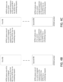
- Table 2B Example resource mapping rules for signaling HARQ ACK/NACK ACK/NACK Bundling No ACK/NACK Bundling Resource Mapping Positive SR, ACK, ACK Negative SR, ACK, ACK (1, 1) Positive SR, NACK, ACK Negative SR, NACK, ACK (0,1) Positive SR, NACK, NACK Positive SR, ACK, NACK Negative SR, ACK, ACK Negative SR, NACK, NACK (0,0) Negative SR, NACK, ACK Negative SR, ACK, NACK (1,0) Negative SR, NACK, NACK Negative SR, ACK, NACK (1,0) Negative SR, NACK, NACK Negative SR, ACK, NACK (1,0) Negative SR, NACK, NACK Negative SR, ACK, NACK, NACK (1,0) Negative SR, NACK, NACK Negative SR, ACK, NACK, NACK, NACK (1,0) Neg
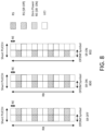
- FIG. 5 is an example diagram that may show ACK/NACK and/or SR transmission.
- the transmission may use frequency shifted RS and may be implicit.
- the WTRU may implicitly transmit one or two bits of ACK/NACK and/or SR using different frequency shifts of Reference Symbol (RS) sequences, such as a CAZAC sequence, in the two consecutive OFDM symbols that may comprise a PUCCH (e.g., a Short PUCCH).
- RS sequences for the two consecutive OFDM symbols may be the same or different cyclic time or frequency shifts of a base sequence.
- the ACK/NACK or SR signaling may be implicit and may be additional to the CSI being transmitted on the resource elements that may not be used for RS.
- An implicit transmission may be an efficient way for UCI signaling in the UL.
- the WTRU may not shift the RS in the frequency in the second OFDM symbol when the WTRU does not request to be scheduled and may shift the RS in the frequency when the WTRU requests to be scheduled as shown in Table 3.
- the WTRU may not shift the RS in the frequency in the second OFDM symbol in the case of NACK or DTX signaling and may shift the RS in the frequency in the second OFDM symbol when transmitting ACK.
- Table 3 shows an example mapping of 1-bit ACK/NACK/DTX or SR to RS frequency shift in the second OFDM symbol
- the WTRU may use a lower RS density to transmit a higher number of bits as shown in Table 4.
- the WTRU may use 1/2 RS density for signaling of one bit of ACK/NACK or SR in the UL.
- the WTRU may use 1/3 RS density to signal more than one bit of information, e.g. ACK/NACK/DTX.
- Discontinuous Transmission (DTX) may imply that neither ACK nor NACK may be transmitted.
- Table 4 An example mapping of ACK/NACK/DTX to RS Shift in the second OFDM symbol is shown in Table 4.
- the WTRU may transmit (e.g., simultaneously transmit) 1-bit ACK/NACK and 1-bit SR using the RS shift approach with the lower RS density of 1/4.
- An example mapping of ACK/NACK and SR to RS Shift in the second OFDM symbol is shown in Table 5.
- the WTRU may use four RS frequency shifts for signaling 2-bit ACK/NACK information as shown in Table 5.
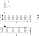
- FIG. 6 is an example diagram that may show ACK/NACK and/or SR transmission using time domain cover code on RS. This may be done implicitly.
- the WTRU may transmit one bit of ACK/NACK and/or SR by applying a time domain cover code on Reference Symbol (RS) sequences, such as a CAZAC sequence, in the two consecutive OFDM symbols that may comprise a PUCCH (e.g., a short PUCCH). That may be done irrespective of the RS density of the PUCCH. Two variants of this approach with RS density of 1/2 and 1/3 may be seen in FIG. 6 .
- the time domain codes may be length-2 Walsh-Hadamard Orthogonal codes.
- An example mapping of SR to cover codes is shown in Table 6.
- the WTRU may use cover code of [1 1] on the two RS symbols (e.g., which may be the equivalent to not applying any cover code).
- the WTRU requests to be scheduled then it may use cover code [1 -1] on the two RS symbols.
- the WTRU may use cover code of [1 1] on the two RS symbols to signal NACK/DTX and cover code [1 -1] to signal ACK.
- a WTRU may implicitly transmit one or two bits of ACK/NACK and/or SR by applying respective (e.g., different) cyclic time shifts of the RS base sequence (e.g., a CAZAC sequence) in the OFDM symbol(s) (e.g., each of two consecutive OFDM symbols) of the PUCCH (e.g., a short PUCCH).
- FIG. 7 is an example diagram that may show ACK/NACK and/or SR transmission (e.g., implicit transmission) using differential cyclic time shifts for RS. Three example scenarios with RS density of 1/1, 1/2, and 1/3 may be shown.
- the WTRU may apply a sequence based scheme for ACK/NACK and/or SR transmission; other UCI (e.g., CSI, PMI, RI, etc.) may or may not be transmitted in this scenario.
- UCI, ACK/NACK and/or SR may be multiplexed on the same PUCCH resources (e.g., short PUCCH resources).
- PUCCH resources e.g., short PUCCH resources.
- the WTRU may use the cyclic shift of m for the RS in the first OFDM symbol and the cyclic time shift of n for the RS in the second OFDM symbol.
- the cyclic time shifts on the two OFDM symbols are different (e.g., m ⁇ n), then it may imply that the WTRU may be requesting to be scheduled for the UL transmission.
- the UL transmission may be PUSCH.
- the WTRU may use the same cyclic time shift for the two RSs on two different OFDM symbols to signal NACK/DTX and use a different cyclic time shift for the two RSs to signal ACK.
- Table 7 shows an example mapping of SR or ACK/NACK/DTX using different cyclic time shifts for RS.
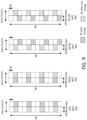
- FIG. 8 shows an example diagram for SR transmission using RS on-off keying, which may be implicit.
- the WTRU may transmit one bit of ACK/NACK and/or SR by turning on or off the Reference Symbols (RS) on the second OFDM symbol of the two consecutive OFDM symbols comprising a PUCCH (e.g., a short PUCCH). This may be done implicitly.
- RS Reference Symbols
- the WTRU when the WTRU does not request to be scheduled, such as when the SR is off, the WTRU may transmit RS on the second OFDM symbol.
- the WTRU does request to be scheduled, such as when SR is equal to one, then the WTRU may not transmit RS on the second OFDM symbol.
- the WTRU may turn off the RS (e.g., not transmitting the RS) on the second OFDM symbol.
- the WTRU may distribute the power of the RS on the remaining REs of the second OFDM symbol within the PUCCH used for UCI transmission.
- the turned off REs on the second OFDM symbol may be interpreted as reserved REs by the receiver with no transmission, such as a zero power RE.
- the WTRU may turn off the RS (e.g., not transmitting the RS) on the second OFDM symbol.
- the WTRU may reallocate REs on the second OFDM symbol to the UCI transmission. For example, no RS may be transmitted on the second OFDM symbol.
- the coding rate for the UCI transmission may be lower, which may result in better BLER performance for the UCI.
- the rate matching may be different for UCI regardless of whether SR may be transmitted or not.
- Table 8 shows an example mapping of SR to the presence of RS in the second OFDM symbol.
- FIG. 9 shows an example diagram for ACK/NACK and/or SR transmission (e.g., implicit transmission of ACK/NACK and/or SR) using RS with waveform coding.
- the waveform coding may include PPM, Manchester coding, and/or the like.
- the WTRU may encode one bit of ACK/NACK and/or SR by using multiple on (e.g., RS is transmitted) OFDM symbols and off (e.g., RS is not transmitted) OFDM symbols.
- the WTRU may encode one bit of ACK/NACK and/or SR by changing the position of the on and off OFDM symbols.
- Manchester coding may be applied between multiple (e.g., two) OFDM symbols of a multi-symbol (e.g., two-symbol) PUCCH (e.g., a short PUCCH).
- ACK may be encoded as follows: one or more REs of a second OFDM symbol may have energy and the same REs in a first OFDM symbol may have zero energy.
- NACK may be encoded as follows: one or more REs of a first OFDM symbol may have energy and the same REs in the following OFDM symbol may have zero energy.
- the WTRU may use any combination of the schemes proposed herein for ACK/NACK and/or SR signaling in the UL.
- a WTRU may use a number of methods to implicitly signal one or more bits of UCI information.
- the WTRU may signal one or more bits of UCI information using any combination of frequency shifted RS and/or Time Domain Cover Code on RS, differential cyclic time shifts for RS, RS on-off keying, RS with waveform coding, and/or the like.
- Signaling of a SR in a PUCCH may be provided.
- the signaling may be explicit.
- SR and UCI may be signaled in a same OFDM symbol.
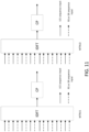
- UCI and SR may be transmitted by multiplexing the sequences or symbols corresponding to the UCI and the SR in frequency as shown in FIG. 10 . Since the SR and UCI symbols may be separated in frequency, the same sequence may be used to transmit both types of data.
- the WTRU does not have a SR to transmit, the subcarriers reserved for SR transmission may be loaded with zeros.
- FIG. 10 shows an example diagram for frequency division multiplexing of UCI and SR.
- the SR and reference symbols (RS) may be transmitted on the same subcarriers but on different OFDM symbols.
- the subcarriers allocated to RS/SR may be used for the transmission of reference symbols.
- SR may be scheduled to be transmitted. If the WTRU does not have a scheduling request to transmit, the subcarriers allocated to RS/SR may be used for the transmission of reference symbols.
- SR may be transmitted. If the WTRU has a scheduling request to transmit, the subcarriers allocated to RS/SR may be used for the transmission of the SR sequence. The receiver may use the SR sequence to also estimate the channel and/or decode the UCI.
- RS and SR sequences may be chosen to be different. For example, they may be different cyclic shifts of the same base sequence or they may be two different base sequences.
- the sequences may be Zadoff Chu sequences, CAZAC sequences, and/or the like.
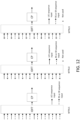
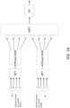
- Orthogonality between the sequences transmitted by a WTRU may be achieved in frequency domain by allocating different subcarriers to the UCI and SR. Orthogonality between the sequences transmitted by different WTRUs may be achieved in frequency domain and/or using orthogonal sequences. For example, in FIG. 11 , WTRU1 and WTRU2 may use orthogonal sequences for the UCI and orthogonal sequences for the SR.
- SR may be transmitted. If the WTRU does not have a scheduling request to transmit, the resource allocated to SR may be used for the transmission of reference symbols.
Landscapes
- Engineering & Computer Science (AREA)
- Signal Processing (AREA)
- Computer Networks & Wireless Communication (AREA)
- Mobile Radio Communication Systems (AREA)
- Detection And Prevention Of Errors In Transmission (AREA)
Priority Applications (1)
| Application Number | Priority Date | Filing Date | Title |
|---|---|---|---|
| EP25168188.8A EP4557648A3 (en) | 2017-05-03 | 2018-05-01 | Methods, systems, and apparatus for transmitting uplink control information |
Applications Claiming Priority (3)
| Application Number | Priority Date | Filing Date | Title |
|---|---|---|---|
| US201762500772P | 2017-05-03 | 2017-05-03 | |
| US201762564755P | 2017-09-28 | 2017-09-28 | |
| PCT/US2018/030428 WO2018204347A1 (en) | 2017-05-03 | 2018-05-01 | Methods, systems, and apparatus for transmitting uplink control information |
Related Child Applications (2)
| Application Number | Title | Priority Date | Filing Date |
|---|---|---|---|
| EP25168188.8A Division-Into EP4557648A3 (en) | 2017-05-03 | 2018-05-01 | Methods, systems, and apparatus for transmitting uplink control information |
| EP25168188.8A Division EP4557648A3 (en) | 2017-05-03 | 2018-05-01 | Methods, systems, and apparatus for transmitting uplink control information |
Publications (2)
| Publication Number | Publication Date |
|---|---|
| EP3619855A1 EP3619855A1 (en) | 2020-03-11 |
| EP3619855B1 true EP3619855B1 (en) | 2025-07-02 |
Family
ID=62200557
Family Applications (2)
| Application Number | Title | Priority Date | Filing Date |
|---|---|---|---|
| EP25168188.8A Pending EP4557648A3 (en) | 2017-05-03 | 2018-05-01 | Methods, systems, and apparatus for transmitting uplink control information |
| EP18725994.0A Active EP3619855B1 (en) | 2017-05-03 | 2018-05-01 | Methods, systems, and apparatus for transmitting uplink control information |
Family Applications Before (1)
| Application Number | Title | Priority Date | Filing Date |
|---|---|---|---|
| EP25168188.8A Pending EP4557648A3 (en) | 2017-05-03 | 2018-05-01 | Methods, systems, and apparatus for transmitting uplink control information |
Country Status (11)
| Country | Link |
|---|---|
| US (2) | US11736259B2 (enExample) |
| EP (2) | EP4557648A3 (enExample) |
| JP (3) | JP2020520147A (enExample) |
| KR (3) | KR20240027897A (enExample) |
| CN (4) | CN110637430B (enExample) |
| BR (1) | BR112019023027A2 (enExample) |
| DK (1) | DK3619855T3 (enExample) |
| HU (1) | HUE072465T2 (enExample) |
| RU (1) | RU2019137555A (enExample) |
| TW (1) | TWI794227B (enExample) |
| WO (1) | WO2018204347A1 (enExample) |
Families Citing this family (24)
| Publication number | Priority date | Publication date | Assignee | Title |
|---|---|---|---|---|
| US10123349B2 (en) | 2015-07-09 | 2018-11-06 | Qualcomm Incorporated | Low latency physical uplink control channel with scheduling request and channel state information |
| CN115866783A (zh) * | 2016-09-30 | 2023-03-28 | 中兴通讯股份有限公司 | 上行控制信息传输方法及装置 |
| US11038656B2 (en) * | 2017-05-31 | 2021-06-15 | Qualcomm Incorporated | Sequence based uplink control information design for new radio |
| HUE060080T2 (hu) * | 2017-05-31 | 2023-01-28 | Ntt Docomo Inc | Felhasználói terminál és vezeték nélküli kommunikációs eljárás |
| US11770830B2 (en) * | 2017-06-07 | 2023-09-26 | Telefonaktiebolaget Lm Ericsson (Publ) | Providing information on a control channel |
| WO2018231626A1 (en) * | 2017-06-14 | 2018-12-20 | Idac Holdings, Inc. | Methods, apparatus, systems, architectures and interfaces for uplink control information (uci) transmission via uplink shared data channel |
| KR20200015513A (ko) | 2017-06-15 | 2020-02-12 | 파나소닉 인텔렉츄얼 프로퍼티 코포레이션 오브 아메리카 | 단말 및 통신 방법 |
| CN109150468B (zh) * | 2017-06-16 | 2020-10-23 | 华为技术有限公司 | 一种传输信息的方法和装置 |
| US11251923B2 (en) * | 2017-07-31 | 2022-02-15 | Qualcomm Incorporated | Uplink ACK/NACK and SR in short durations |
| US10911189B2 (en) * | 2017-08-11 | 2021-02-02 | Qualcomm Incorporated | Uplink control information (UCI) in short duration |
| CN109391427B (zh) | 2017-08-11 | 2021-03-30 | 华为技术有限公司 | 一种通信方法及设备 |
| CN115642994B (zh) | 2017-08-11 | 2025-04-25 | 韦勒斯标准与技术协会公司 | 发送或接收上行链路控制信道的方法、设备和系统 |
| EP3737018B1 (en) * | 2018-02-13 | 2023-08-16 | Huawei Technologies Co., Ltd. | Method and apparatus for transmitting uplink control information |
| US10911191B2 (en) * | 2018-09-27 | 2021-02-02 | Centre Of Excellence In Wireless Technology | Method and apparatus for managing communication operations in orthogonal frequency division multiplexing system |
| US11956103B2 (en) * | 2018-10-31 | 2024-04-09 | Lg Electronics Inc. | Method for transmitting and receiving SRS in wireless communication system, and device for same |
| US12250704B2 (en) * | 2019-01-25 | 2025-03-11 | Qualcomm Incorporated | Preconfigured uplink resource techniques in wireless communications |
| CN111800863B (zh) | 2019-07-19 | 2023-12-19 | 维沃移动通信有限公司 | 参数确定、信息配置方法和设备 |
| WO2021037245A1 (en) * | 2019-08-29 | 2021-03-04 | Guangdong Oppo Mobile Telecommunications Corp., Ltd. | Apparatus and information processing method |
| US12219566B2 (en) * | 2021-01-13 | 2025-02-04 | Qualcomm Incorporated | Uplink control information multiplexing |
| US12245238B2 (en) * | 2021-01-13 | 2025-03-04 | Qualcomm Incorporated | Uplink control information multiplexing |
| WO2022174818A1 (zh) * | 2021-02-20 | 2022-08-25 | 上海推络通信科技合伙企业(有限合伙) | 一种用于无线通信的节点中的方法和装置 |
| US20230106447A1 (en) * | 2021-10-01 | 2023-04-06 | Qualcomm Incorporated | Cyclic shifts for multiple resource block physical uplink control channel communications |
| US20240292401A1 (en) * | 2023-02-24 | 2024-08-29 | Qualcomm Incorporated | Optimized subframe blanking for dual sim dual active |
| EP4462714A1 (en) * | 2023-05-04 | 2024-11-13 | Mavenir Systems, Inc. | Improving downlink throughput of 5g nr using pucch harq resource assignment |
Family Cites Families (106)
| Publication number | Priority date | Publication date | Assignee | Title |
|---|---|---|---|---|
| US8479122B2 (en) | 2004-07-30 | 2013-07-02 | Apple Inc. | Gestures for touch sensitive input devices |
| WO2006050559A1 (en) | 2004-11-10 | 2006-05-18 | Resmed Limited | Method and apparatus for adjusting respiratory mask sealing force |
| US7432916B2 (en) | 2004-12-09 | 2008-10-07 | Universal Electronics, Inc. | Controlling device with dual-mode, touch-sensitive display |
| US7448572B2 (en) | 2005-10-05 | 2008-11-11 | Lockheed Martin Corporation | Direct mounted propulsion for non-rigid airships |
| JP4952138B2 (ja) | 2006-08-17 | 2012-06-13 | 富士通株式会社 | 中継局、無線基地局及び通信方法 |
| US8571120B2 (en) * | 2006-09-22 | 2013-10-29 | Texas Instruments Incorporated | Transmission of acknowledge/not acknowledge (ACK/NACK) bits and their embedding in the reference signal |
| EP2168269A4 (en) | 2007-09-14 | 2014-09-24 | Lg Electronics Inc | METHOD FOR TRANSMITTING CONTROL MESSAGES IN WIRELESS COMMUNICATION ARRANGEMENTS |
| CN101252422B (zh) | 2008-03-20 | 2013-06-05 | 中兴通讯股份有限公司 | 物理混合重传指示信道的分配方法 |
| US8218663B2 (en) * | 2008-07-29 | 2012-07-10 | Texas Instruments Incorporated | Reference signal resource allocation for single user MIMO |
| WO2010013961A2 (en) | 2008-07-30 | 2010-02-04 | Lg Electronics Inc. | Method and apparatus of monitoring pdcch in wireless communication system |
| KR20100019947A (ko) | 2008-08-11 | 2010-02-19 | 엘지전자 주식회사 | 무선 통신 시스템에서 정보 전송 방법 |
| KR101571566B1 (ko) * | 2008-08-11 | 2015-11-25 | 엘지전자 주식회사 | 무선 통신 시스템에서 제어신호 전송 방법 |
| KR101328790B1 (ko) | 2008-10-20 | 2013-11-13 | 인터디지탈 패튼 홀딩스, 인크 | 반송파 집적 방법 |
| CN103716892B (zh) | 2009-03-12 | 2017-06-09 | 交互数字专利控股公司 | 由wtru实施的用于多载波操作的方法以及该wtru |
| KR101186619B1 (ko) | 2009-03-29 | 2012-09-27 | 엘지전자 주식회사 | 무선 통신 시스템에서 제어 신호 송신 방법 및 이를 위한 장치 |
| US8885479B2 (en) | 2009-05-07 | 2014-11-11 | Qualcomm Incorporated | Multicarrier retransmission feedback |
| US8964621B2 (en) | 2009-05-08 | 2015-02-24 | Qualcomm Incorporated | Transmission and reception of a reference signal supporting positioning in a wireless communication network |
| KR101643636B1 (ko) | 2009-06-02 | 2016-07-29 | 엘지전자 주식회사 | 무선 통신 시스템에서 ack/nack 시퀀스 정보를 송신하는 방법 및 이를 위한 장치 |
| CN101932089A (zh) | 2009-06-24 | 2010-12-29 | 宏达国际电子股份有限公司 | 改善功率控制机制的方法及其相关通讯装置 |
| JP2011035861A (ja) | 2009-08-06 | 2011-02-17 | Sharp Corp | 移動局装置、無線通信方法および移動局装置の制御プログラム |
| KR101897448B1 (ko) | 2009-10-01 | 2018-10-08 | 인터디지탈 패튼 홀딩스, 인크 | 업링크 제어 데이터 전송 |
| WO2011042040A1 (en) | 2009-10-05 | 2011-04-14 | Nokia Siemens Networks Oy | Uplink transmission mode switching in single user multiple- input communication |
| WO2011082829A1 (en) | 2010-01-08 | 2011-07-14 | Nokia Siemens Networks Oy | Method and apparatus for using demodulation reference signal multiplexing in wireless communication |
| KR101753586B1 (ko) | 2010-02-03 | 2017-07-04 | 엘지전자 주식회사 | 무선 통신 시스템에서 제어 정보의 전송 방법 및 장치 |
| CN104935368B (zh) | 2010-04-12 | 2018-07-24 | Lg电子株式会社 | 在支持多天线的无线通信系统中的有效反馈的方法和设备 |
| CN101854496A (zh) | 2010-04-28 | 2010-10-06 | 青岛海信电器股份有限公司 | 电视机控制方法、遥控器及电视机 |
| KR20110120808A (ko) | 2010-04-29 | 2011-11-04 | 엘지전자 주식회사 | 하향링크 ack/nack 신호 전송방법 및 기지국과, 하향링크 ack/nack 신호 수신방법 및 사용자기기 |
| DK2564547T3 (en) | 2010-04-30 | 2018-09-03 | Guangdong Oppo Mobile Telecommunications Corp Ltd | SYSTEM AND PROCEDURE FOR SHARING A CONTROL CHANNEL FOR SUSTAINABLE GOVERNMENT |
| WO2012015214A2 (ko) * | 2010-07-26 | 2012-02-02 | 엘지전자 주식회사 | 무선 통신 시스템에서 확장된 상향링크 제어정보를 전송하는 방법 및 장치 |
| US8670379B2 (en) | 2010-10-02 | 2014-03-11 | Sharp Kabushiki Kaisha | Uplink control information multiplexing on the physical uplink control channel for LTE-A |
| CN102971981B (zh) | 2010-10-28 | 2015-12-16 | Lg电子株式会社 | 用于发送控制信息的方法和装置 |
| JP4948671B1 (ja) | 2010-10-29 | 2012-06-06 | シャープ株式会社 | 移動局装置、処理方法および集積回路 |
| JP5388370B2 (ja) | 2010-11-12 | 2014-01-15 | 株式会社Nttドコモ | 無線基地局装置、移動端末装置及び送信電力制御方法 |
| KR101907528B1 (ko) | 2011-02-18 | 2018-10-12 | 삼성전자 주식회사 | 이동 통신 시스템 및 그 이동 통신 시스템에서 채널 송수신 방법 |
| US9225503B2 (en) | 2011-05-02 | 2015-12-29 | Lg Electronics Inc. | Method for transmitting/receiving data in wireless communication system and base station for same |
| WO2012150793A2 (ko) | 2011-05-03 | 2012-11-08 | 엘지전자 주식회사 | 무선 통신 시스템에서 하향링크 제어 정보를 송수신하는 방법 및 이를 위한 장치 |
| WO2012169859A2 (ko) * | 2011-06-10 | 2012-12-13 | 엘지전자 주식회사 | 제어 정보를 전송하는 방법 및 이를 위한 장치 |
| US8693420B2 (en) | 2011-08-10 | 2014-04-08 | Futurewei Technologies, Inc. | System and method for signaling and transmitting uplink reference signals |
| US9252918B2 (en) | 2011-08-15 | 2016-02-02 | Google Technology Holdings LLC | Method and apparatus for control channel transmission and reception |
| US8743791B2 (en) | 2011-09-22 | 2014-06-03 | Samsung Electronics Co., Ltd. | Apparatus and method for uplink transmission in wireless communication systems |
| WO2013051983A1 (en) | 2011-10-03 | 2013-04-11 | Telefonaktiebolaget L M Ericsson (Publ) | Simultaneous reporting of ack/nack and channel-state information using pucch format 3 resources |
| US9241328B2 (en) | 2011-10-12 | 2016-01-19 | Lg Electronics Inc. | Data transceiving method and apparatus for same |
| US9660782B2 (en) | 2011-10-19 | 2017-05-23 | Lg Electronics Inc. | Method and apparatus for transceiving downlink control information in a wireless access system |
| CN102420685B (zh) | 2011-11-07 | 2014-08-06 | 电信科学技术研究院 | 一种传输控制信息的方法及装置 |
| WO2013071486A1 (en) | 2011-11-15 | 2013-05-23 | Nokia Siemens Networks Oy | A method and apparatus |
| CN103178926B (zh) * | 2011-12-21 | 2016-01-06 | 华为技术有限公司 | 传输控制信息的方法、用户设备和基站 |
| US9137781B2 (en) | 2012-01-06 | 2015-09-15 | Industrial Technology Research Institute | Method of handling hybrid automatic repeat request resources in wireless communication system |
| CN113225172B (zh) | 2012-01-27 | 2024-05-24 | 交互数字专利控股公司 | 由WTRU执行的用于ePDCCH的方法 |
| US9369239B2 (en) | 2012-02-19 | 2016-06-14 | Lg Electronics Inc. | Method and apparatus for transmitting acknowledgments in wireless communication systems |
| US8995377B2 (en) | 2012-05-11 | 2015-03-31 | Blackberry Limited | PHICH resource provisioning in time division duplex systems |
| JP2013243460A (ja) | 2012-05-18 | 2013-12-05 | Sharp Corp | 端末、基地局、通信システムおよび通信方法 |
| TWI632786B (zh) | 2012-06-04 | 2018-08-11 | 內數位專利控股公司 | 無線發射/接收單元及由其實施的方法 |
| WO2014007493A1 (ko) | 2012-07-02 | 2014-01-09 | 주식회사 케이티 | 상향링크 사운딩 참조신호 송수신 방법과 그 장치 |
| US9504037B2 (en) * | 2012-08-01 | 2016-11-22 | Lg Electronics Inc. | Method and apparatus for transmitting and receiving data |
| GB201214137D0 (en) | 2012-08-07 | 2012-09-19 | Gen Dynamics Broadband Inc | Communication unit, integrated circuit and method for supporting a virtual carrier |
| CN107733628B (zh) | 2012-09-21 | 2020-09-01 | Lg电子株式会社 | 在无线通信系统中接收下行链路控制信号的方法和装置 |
| EP2903375B1 (en) | 2012-09-27 | 2016-12-28 | Sun Patent Trust | Wireless communication terminal, base station device, and resource allocation method |
| CN103780361B (zh) | 2012-10-17 | 2018-08-17 | 中兴通讯股份有限公司 | 一种应答信息的发送方法及装置 |
| JP5832663B2 (ja) | 2012-10-31 | 2015-12-16 | エルジー エレクトロニクス インコーポレイティド | 制御情報を送受信する方法及びそのための装置 |
| US9973297B2 (en) | 2013-01-11 | 2018-05-15 | Interdigital Patent Holdings, Inc. | System and method for adaptive modulation |
| US9036580B2 (en) | 2013-01-17 | 2015-05-19 | Sharp Laboratories Of America, Inc. | Systems and methods for dynamically configuring a flexible subframe |
| US9781738B2 (en) | 2013-02-07 | 2017-10-03 | Idac Holdings, Inc. | Physical layer (PHY) design for a low latency millimeter wave (MMW) backhaul system |
| US10448351B2 (en) | 2013-04-02 | 2019-10-15 | Qualcomm Incorporated | Employing neighboring cell assistance information for interference mitigation |
| EP2982076A2 (en) | 2013-04-03 | 2016-02-10 | Interdigital Patent Holdings, Inc. | Epdcch common search space design for one or more carrier types |
| US9794026B2 (en) | 2013-04-12 | 2017-10-17 | Qualcomm Incorporated | Adaptive data interference cancellation |
| US9755810B2 (en) | 2013-04-12 | 2017-09-05 | Qualcomm Incorporated | Precoder resource bundling information for interference cancellation in LTE |
| KR101765751B1 (ko) * | 2013-06-11 | 2017-08-07 | 노키아 솔루션스 앤드 네트웍스 오와이 | 계층 이동성 |
| US9642140B2 (en) * | 2013-06-18 | 2017-05-02 | Samsung Electronics Co., Ltd. | Methods of UL TDM for inter-enodeb carrier aggregation |
| WO2015021318A2 (en) | 2013-08-07 | 2015-02-12 | Interdigital Patent Holdings, Inc. | Coverage enhancements of low cost mtc devices in uplink/downlink decoupled scenario |
| EP2836044A1 (en) | 2013-08-08 | 2015-02-11 | Panasonic Intellectual Property Corporation of America | Dynamic scheduling for subframe bundling |
| US20150085720A1 (en) | 2013-09-26 | 2015-03-26 | Qualcomm Incorporated | Reduced delay harq process timeline for fdd-tdd carrier aggregation |
| JP6298263B2 (ja) | 2013-09-26 | 2018-03-20 | 株式会社Nttドコモ | 無線基地局、ユーザ端末及び無線通信方法 |
| US9584284B2 (en) | 2013-09-26 | 2017-02-28 | Qualcomm Incorporated | Simplified FDD-TDD carrier aggregation |
| JP2015070442A (ja) | 2013-09-27 | 2015-04-13 | 京セラ株式会社 | ユーザ端末、基地局、及びプロセッサ |
| KR20150060118A (ko) | 2013-11-25 | 2015-06-03 | 주식회사 아이티엘 | Harq ack/nack의 전송방법 및 장치 |
| JP2014096805A (ja) | 2013-12-03 | 2014-05-22 | Ntt Docomo Inc | 移動端末装置、無線通信方法及び無線通信システム |
| US20150189574A1 (en) | 2013-12-26 | 2015-07-02 | Samsung Electronics Co., Ltd. | Methods for dormant cell signaling for advanced cellular network |
| US10411838B2 (en) | 2014-01-23 | 2019-09-10 | Qualcomm Incorporated | Coverage enhancements with carrier aggregation |
| CN110856242B (zh) | 2014-01-29 | 2023-07-25 | 交互数字专利控股公司 | 无线通信中的上行链路传输 |
| US9749144B2 (en) | 2014-01-30 | 2017-08-29 | Qualcomm Incorporated | MBSFN and RS considerations in bundled transmission design |
| US10153867B2 (en) | 2014-01-30 | 2018-12-11 | Qualcomm Incorporated | Carrier aggregation with dynamic TDD DL/UL subframe configuration |
| WO2015119559A1 (en) | 2014-02-10 | 2015-08-13 | Telefonaktiebolaget L M Ericsson (Publ) | Reference signal coupling in a wireless network |
| US10862634B2 (en) | 2014-03-07 | 2020-12-08 | Huawei Technologies Co., Ltd. | Systems and methods for OFDM with flexible sub-carrier spacing and symbol duration |
| EP3340523B1 (en) | 2014-03-20 | 2021-01-13 | Interdigital Patent Holdings, Inc. | Method and apparatus for non-orthogonal access in lte systems |
| JP6599355B2 (ja) | 2014-04-03 | 2019-10-30 | エルジー エレクトロニクス インコーポレイティド | 端末と基地局との間の二重接続におけるパワーヘッドルーム報告を送信する方法および端末 |
| KR20160133503A (ko) | 2014-05-12 | 2016-11-22 | 인텔 코포레이션 | C-ran 프론트엔드 전처리 및 시그널링 유닛 |
| EP3998819B1 (en) | 2014-06-24 | 2024-04-24 | Sun Patent Trust | Terminal, base station, transmission method, and reception method |
| WO2016004634A1 (en) | 2014-07-11 | 2016-01-14 | Mediatek Singapore Pte. Ltd. | Method for enb, ue uplink transmission and reception |
| WO2016018469A1 (en) | 2014-08-01 | 2016-02-04 | Intel IP Corporation | Pdcch design for narrowband deployment |
| EP3195508A1 (en) | 2014-09-08 | 2017-07-26 | Interdigital Patent Holdings, Inc. | Systems and methods of operating with different transmission time interval (tti) durations |
| WO2016039599A1 (en) | 2014-09-12 | 2016-03-17 | Lg Electronics Inc. | Method and apparatus for supporting coexistence in unlicensed band among cells of different operators in wireless communication system |
| US9980257B2 (en) * | 2014-09-26 | 2018-05-22 | Qualcomm Incorporated | Ultra-low latency LTE reference signal transmission |
| US9955462B2 (en) | 2014-09-26 | 2018-04-24 | Qualcomm Incorporated | Ultra-low latency LTE control data communication |
| US11581999B2 (en) | 2014-10-08 | 2023-02-14 | Qualcomm Incorporated | Reference signal design for wireless communications |
| US10560235B2 (en) | 2014-10-31 | 2020-02-11 | Qualcomm Incorporated | Narrowband control channel decoding |
| US9749097B2 (en) | 2015-06-04 | 2017-08-29 | Litepoint Corporation | Method for wireless communications testing using downlink and uplink transmissions between an access point and mobile terminals |
| CN114727400B (zh) | 2015-08-11 | 2025-07-29 | 三菱电机株式会社 | 通信系统 |
| US10342005B2 (en) * | 2015-08-14 | 2019-07-02 | Telefonaktiebolaget Lm Ericsson (Publ) | Methods for determining a HARQ-ACK codebook size for a user equipment and base station |
| CN106559198B (zh) * | 2015-09-25 | 2019-09-17 | 电信科学技术研究院 | 一种基于pucch的上行控制信息传输方法及装置 |
| CN120223245A (zh) * | 2015-11-04 | 2025-06-27 | 交互数字专利控股公司 | 用于窄带lte操作的方法和过程 |
| WO2017099521A1 (ko) * | 2015-12-10 | 2017-06-15 | 엘지전자(주) | 짧은 전송 시간 간격을 지원하는 무선 통신 시스템에서 상향링크 신호를 전송하기 위한 방법 및 이를 지원하는 장치 |
| US20190312669A1 (en) * | 2016-03-29 | 2019-10-10 | Lg Electronics Inc. | Method for transmitting channel state information in wireless communication system, and apparatus therefor |
| CN109076050A (zh) * | 2016-04-27 | 2018-12-21 | 夏普株式会社 | 终端装置、基站装置、通信方法以及集成电路 |
| WO2018050094A1 (en) | 2016-09-14 | 2018-03-22 | Mediatek Inc. | Short pucch in nr networks |
| WO2018203407A1 (ja) * | 2017-05-02 | 2018-11-08 | 株式会社Nttドコモ | ユーザ端末及び無線通信方法 |
| CN107563748B (zh) | 2017-08-31 | 2021-05-28 | 网易宝有限公司 | 用于账户的处理方法及装置、介质和计算设备 |
-
2018
- 2018-05-01 DK DK18725994.0T patent/DK3619855T3/da active
- 2018-05-01 KR KR1020247006200A patent/KR20240027897A/ko active Pending
- 2018-05-01 CN CN201880029448.2A patent/CN110637430B/zh active Active
- 2018-05-01 RU RU2019137555A patent/RU2019137555A/ru unknown
- 2018-05-01 CN CN202510484669.0A patent/CN120263357A/zh active Pending
- 2018-05-01 JP JP2019560185A patent/JP2020520147A/ja active Pending
- 2018-05-01 KR KR1020227013717A patent/KR102642287B1/ko active Active
- 2018-05-01 KR KR1020197032445A patent/KR20200012842A/ko not_active Ceased
- 2018-05-01 CN CN202510482973.1A patent/CN120263356A/zh active Pending
- 2018-05-01 EP EP25168188.8A patent/EP4557648A3/en active Pending
- 2018-05-01 HU HUE18725994A patent/HUE072465T2/hu unknown
- 2018-05-01 US US16/610,222 patent/US11736259B2/en active Active
- 2018-05-01 EP EP18725994.0A patent/EP3619855B1/en active Active
- 2018-05-01 BR BR112019023027-0A patent/BR112019023027A2/pt unknown
- 2018-05-01 WO PCT/US2018/030428 patent/WO2018204347A1/en not_active Ceased
- 2018-05-01 CN CN202310087482.8A patent/CN116132000B/zh active Active
- 2018-05-03 TW TW107115022A patent/TWI794227B/zh active
-
2023
- 2023-02-27 JP JP2023028380A patent/JP7601928B2/ja active Active
- 2023-06-21 US US18/338,879 patent/US12483373B2/en active Active
-
2024
- 2024-12-05 JP JP2024212203A patent/JP7791298B2/ja active Active
Also Published As
| Publication number | Publication date |
|---|---|
| US11736259B2 (en) | 2023-08-22 |
| RU2021132082A (ru) | 2021-11-17 |
| JP2023054357A (ja) | 2023-04-13 |
| JP2020520147A (ja) | 2020-07-02 |
| CN110637430B (zh) | 2023-04-18 |
| TW201906353A (zh) | 2019-02-01 |
| US12483373B2 (en) | 2025-11-25 |
| WO2018204347A1 (en) | 2018-11-08 |
| US20200067680A1 (en) | 2020-02-27 |
| JP2025029154A (ja) | 2025-03-05 |
| CN110637430A (zh) | 2019-12-31 |
| KR20240027897A (ko) | 2024-03-04 |
| RU2019137555A3 (enExample) | 2021-09-03 |
| CN116132000B (zh) | 2025-04-18 |
| BR112019023027A2 (pt) | 2020-08-11 |
| KR20220059555A (ko) | 2022-05-10 |
| KR102642287B1 (ko) | 2024-02-28 |
| JP7791298B2 (ja) | 2025-12-23 |
| KR20200012842A (ko) | 2020-02-05 |
| RU2019137555A (ru) | 2021-05-24 |
| US20230336316A1 (en) | 2023-10-19 |
| CN120263357A (zh) | 2025-07-04 |
| TWI794227B (zh) | 2023-03-01 |
| CN116132000A (zh) | 2023-05-16 |
| EP3619855A1 (en) | 2020-03-11 |
| EP4557648A2 (en) | 2025-05-21 |
| WO2018204347A8 (en) | 2019-11-28 |
| CN120263356A (zh) | 2025-07-04 |
| JP7601928B2 (ja) | 2024-12-17 |
| DK3619855T3 (da) | 2025-08-18 |
| HUE072465T2 (hu) | 2025-11-28 |
| EP4557648A3 (en) | 2025-09-03 |
Similar Documents
| Publication | Publication Date | Title |
|---|---|---|
| US12483373B2 (en) | Methods, systems, and apparatus for transmitting uplink control information | |
| US12375248B2 (en) | Method and apparatus for physical sidelink control channel (PSCCH) design in new radio (NR) | |
| US20220201654A1 (en) | Nr sl psfch transmission and monitoring | |
| US20240388386A1 (en) | Harq-ack codebook adaptation | |
| JP7730888B2 (ja) | 時間及び符号ドメインカバレッジ拡張 | |
| WO2020033704A1 (en) | Enhanced sidelink control transmission | |
| WO2019099670A1 (en) | Method and apparatus for harq-ack codebook size determination and resource selection in nr | |
| WO2018231621A1 (en) | Group-common physical downlink control channels for wireless communication | |
| EP3566535A1 (en) | Collision mitigation procedures for grant-less uplink multiple access | |
| WO2018175578A1 (en) | Resource allocation for uplink control channel | |
| RU2837272C2 (ru) | Способы, системы и устройство для передачи информации управления восходящей линии связи | |
| HK40014231B (en) | Methods, systems, and apparatus for transmitting uplink control information | |
| HK40014231A (en) | Methods, systems, and apparatus for transmitting uplink control information | |
| EP4612818A1 (en) | Opportunistic acknowledgment transmissions | |
| WO2024206451A1 (en) | Frequency bundled transmission (fbt) approaches for ultra-reliable low latency communication (urllc) systems |
Legal Events
| Date | Code | Title | Description |
|---|---|---|---|
| STAA | Information on the status of an ep patent application or granted ep patent |
Free format text: STATUS: UNKNOWN |
|
| STAA | Information on the status of an ep patent application or granted ep patent |
Free format text: STATUS: THE INTERNATIONAL PUBLICATION HAS BEEN MADE |
|
| PUAI | Public reference made under article 153(3) epc to a published international application that has entered the european phase |
Free format text: ORIGINAL CODE: 0009012 |
|
| STAA | Information on the status of an ep patent application or granted ep patent |
Free format text: STATUS: REQUEST FOR EXAMINATION WAS MADE |
|
| 17P | Request for examination filed |
Effective date: 20191105 |
|
| AK | Designated contracting states |
Kind code of ref document: A1 Designated state(s): AL AT BE BG CH CY CZ DE DK EE ES FI FR GB GR HR HU IE IS IT LI LT LU LV MC MK MT NL NO PL PT RO RS SE SI SK SM TR |
|
| AX | Request for extension of the european patent |
Extension state: BA ME |
|
| DAV | Request for validation of the european patent (deleted) | ||
| DAX | Request for extension of the european patent (deleted) | ||
| REG | Reference to a national code |
Ref country code: HK Ref legal event code: DE Ref document number: 40014231 Country of ref document: HK |
|
| STAA | Information on the status of an ep patent application or granted ep patent |
Free format text: STATUS: EXAMINATION IS IN PROGRESS |
|
| 17Q | First examination report despatched |
Effective date: 20211108 |
|
| RAP1 | Party data changed (applicant data changed or rights of an application transferred) |
Owner name: INTERDIGITAL PATENT HOLDINGS, INC. |
|
| GRAP | Despatch of communication of intention to grant a patent |
Free format text: ORIGINAL CODE: EPIDOSNIGR1 |
|
| STAA | Information on the status of an ep patent application or granted ep patent |
Free format text: STATUS: GRANT OF PATENT IS INTENDED |
|
| INTG | Intention to grant announced |
Effective date: 20240618 |
|
| GRAJ | Information related to disapproval of communication of intention to grant by the applicant or resumption of examination proceedings by the epo deleted |
Free format text: ORIGINAL CODE: EPIDOSDIGR1 |
|
| STAA | Information on the status of an ep patent application or granted ep patent |
Free format text: STATUS: EXAMINATION IS IN PROGRESS |
|
| INTC | Intention to grant announced (deleted) | ||
| GRAP | Despatch of communication of intention to grant a patent |
Free format text: ORIGINAL CODE: EPIDOSNIGR1 |
|
| STAA | Information on the status of an ep patent application or granted ep patent |
Free format text: STATUS: GRANT OF PATENT IS INTENDED |
|
| INTG | Intention to grant announced |
Effective date: 20241213 |
|
| GRAS | Grant fee paid |
Free format text: ORIGINAL CODE: EPIDOSNIGR3 |
|
| P01 | Opt-out of the competence of the unified patent court (upc) registered |
Free format text: CASE NUMBER: APP_17265/2025 Effective date: 20250409 |
|
| GRAA | (expected) grant |
Free format text: ORIGINAL CODE: 0009210 |
|
| STAA | Information on the status of an ep patent application or granted ep patent |
Free format text: STATUS: THE PATENT HAS BEEN GRANTED |
|
| AK | Designated contracting states |
Kind code of ref document: B1 Designated state(s): AL AT BE BG CH CY CZ DE DK EE ES FI FR GB GR HR HU IE IS IT LI LT LU LV MC MK MT NL NO PL PT RO RS SE SI SK SM TR |
|
| REG | Reference to a national code |
Ref country code: GB Ref legal event code: FG4D |
|
| REG | Reference to a national code |
Ref country code: CH Ref legal event code: EP |
|
| REG | Reference to a national code |
Ref country code: DE Ref legal event code: R096 Ref document number: 602018083173 Country of ref document: DE |
|
| REG | Reference to a national code |
Ref country code: IE Ref legal event code: FG4D |
|
| REG | Reference to a national code |
Ref country code: DK Ref legal event code: T3 Effective date: 20250806 |
|
| REG | Reference to a national code |
Ref country code: NL Ref legal event code: FP |
|
| REG | Reference to a national code |
Ref country code: HU Ref legal event code: AG4A Ref document number: E072465 Country of ref document: HU |
|
| PG25 | Lapsed in a contracting state [announced via postgrant information from national office to epo] |
Ref country code: PT Free format text: LAPSE BECAUSE OF FAILURE TO SUBMIT A TRANSLATION OF THE DESCRIPTION OR TO PAY THE FEE WITHIN THE PRESCRIBED TIME-LIMIT Effective date: 20251103 |
|
| REG | Reference to a national code |
Ref country code: AT Ref legal event code: MK05 Ref document number: 1810503 Country of ref document: AT Kind code of ref document: T Effective date: 20250702 |