EP3619460B1 - Dispositif d'éclairage et luminaire - Google Patents
Dispositif d'éclairage et luminaire Download PDFInfo
- Publication number
- EP3619460B1 EP3619460B1 EP18719216.6A EP18719216A EP3619460B1 EP 3619460 B1 EP3619460 B1 EP 3619460B1 EP 18719216 A EP18719216 A EP 18719216A EP 3619460 B1 EP3619460 B1 EP 3619460B1
- Authority
- EP
- European Patent Office
- Prior art keywords
- light
- light guide
- led
- filament
- lighting device
- Prior art date
- Legal status (The legal status is an assumption and is not a legal conclusion. Google has not performed a legal analysis and makes no representation as to the accuracy of the status listed.)
- Active
Links
- 238000010168 coupling process Methods 0.000 claims description 25
- 238000005859 coupling reaction Methods 0.000 claims description 25
- 239000000758 substrate Substances 0.000 claims description 9
- 230000008878 coupling Effects 0.000 claims description 4
- 230000000694 effects Effects 0.000 description 32
- 230000004313 glare Effects 0.000 description 23
- 239000000463 material Substances 0.000 description 7
- 230000007423 decrease Effects 0.000 description 5
- 239000008393 encapsulating agent Substances 0.000 description 5
- OAICVXFJPJFONN-UHFFFAOYSA-N Phosphorus Chemical compound [P] OAICVXFJPJFONN-UHFFFAOYSA-N 0.000 description 4
- GWEVSGVZZGPLCZ-UHFFFAOYSA-N Titan oxide Chemical compound O=[Ti]=O GWEVSGVZZGPLCZ-UHFFFAOYSA-N 0.000 description 4
- TZCXTZWJZNENPQ-UHFFFAOYSA-L barium sulfate Chemical compound [Ba+2].[O-]S([O-])(=O)=O TZCXTZWJZNENPQ-UHFFFAOYSA-L 0.000 description 4
- 238000005253 cladding Methods 0.000 description 3
- 230000003247 decreasing effect Effects 0.000 description 3
- 230000001419 dependent effect Effects 0.000 description 3
- 230000003287 optical effect Effects 0.000 description 3
- PNEYBMLMFCGWSK-UHFFFAOYSA-N aluminium oxide Inorganic materials [O-2].[O-2].[O-2].[Al+3].[Al+3] PNEYBMLMFCGWSK-UHFFFAOYSA-N 0.000 description 2
- 230000000875 corresponding effect Effects 0.000 description 2
- 229910052593 corundum Inorganic materials 0.000 description 2
- 239000002245 particle Substances 0.000 description 2
- 239000002861 polymer material Substances 0.000 description 2
- 229920001296 polysiloxane Polymers 0.000 description 2
- 238000007789 sealing Methods 0.000 description 2
- 229910001845 yogo sapphire Inorganic materials 0.000 description 2
- 239000003086 colorant Substances 0.000 description 1
- 230000021615 conjugation Effects 0.000 description 1
- 230000002596 correlated effect Effects 0.000 description 1
- 239000000835 fiber Substances 0.000 description 1
- 239000011521 glass Substances 0.000 description 1
- 238000000034 method Methods 0.000 description 1
- 239000002096 quantum dot Substances 0.000 description 1
- 238000009877 rendering Methods 0.000 description 1
- 239000007787 solid Substances 0.000 description 1
Images


Classifications
-
- F—MECHANICAL ENGINEERING; LIGHTING; HEATING; WEAPONS; BLASTING
- F21—LIGHTING
- F21K—NON-ELECTRIC LIGHT SOURCES USING LUMINESCENCE; LIGHT SOURCES USING ELECTROCHEMILUMINESCENCE; LIGHT SOURCES USING CHARGES OF COMBUSTIBLE MATERIAL; LIGHT SOURCES USING SEMICONDUCTOR DEVICES AS LIGHT-GENERATING ELEMENTS; LIGHT SOURCES NOT OTHERWISE PROVIDED FOR
- F21K9/00—Light sources using semiconductor devices as light-generating elements, e.g. using light-emitting diodes [LED] or lasers
- F21K9/60—Optical arrangements integrated in the light source, e.g. for improving the colour rendering index or the light extraction
- F21K9/61—Optical arrangements integrated in the light source, e.g. for improving the colour rendering index or the light extraction using light guides
-
- F—MECHANICAL ENGINEERING; LIGHTING; HEATING; WEAPONS; BLASTING
- F21—LIGHTING
- F21K—NON-ELECTRIC LIGHT SOURCES USING LUMINESCENCE; LIGHT SOURCES USING ELECTROCHEMILUMINESCENCE; LIGHT SOURCES USING CHARGES OF COMBUSTIBLE MATERIAL; LIGHT SOURCES USING SEMICONDUCTOR DEVICES AS LIGHT-GENERATING ELEMENTS; LIGHT SOURCES NOT OTHERWISE PROVIDED FOR
- F21K9/00—Light sources using semiconductor devices as light-generating elements, e.g. using light-emitting diodes [LED] or lasers
- F21K9/20—Light sources comprising attachment means
- F21K9/23—Retrofit light sources for lighting devices with a single fitting for each light source, e.g. for substitution of incandescent lamps with bayonet or threaded fittings
- F21K9/232—Retrofit light sources for lighting devices with a single fitting for each light source, e.g. for substitution of incandescent lamps with bayonet or threaded fittings specially adapted for generating an essentially omnidirectional light distribution, e.g. with a glass bulb
-
- G—PHYSICS
- G02—OPTICS
- G02B—OPTICAL ELEMENTS, SYSTEMS OR APPARATUS
- G02B6/00—Light guides; Structural details of arrangements comprising light guides and other optical elements, e.g. couplings
- G02B6/0001—Light guides; Structural details of arrangements comprising light guides and other optical elements, e.g. couplings specially adapted for lighting devices or systems
- G02B6/0005—Light guides; Structural details of arrangements comprising light guides and other optical elements, e.g. couplings specially adapted for lighting devices or systems the light guides being of the fibre type
- G02B6/001—Light guides; Structural details of arrangements comprising light guides and other optical elements, e.g. couplings specially adapted for lighting devices or systems the light guides being of the fibre type the light being emitted along at least a portion of the lateral surface of the fibre
-
- F—MECHANICAL ENGINEERING; LIGHTING; HEATING; WEAPONS; BLASTING
- F21—LIGHTING
- F21Y—INDEXING SCHEME ASSOCIATED WITH SUBCLASSES F21K, F21L, F21S and F21V, RELATING TO THE FORM OR THE KIND OF THE LIGHT SOURCES OR OF THE COLOUR OF THE LIGHT EMITTED
- F21Y2113/00—Combination of light sources
- F21Y2113/20—Combination of light sources of different form
-
- F—MECHANICAL ENGINEERING; LIGHTING; HEATING; WEAPONS; BLASTING
- F21—LIGHTING
- F21Y—INDEXING SCHEME ASSOCIATED WITH SUBCLASSES F21K, F21L, F21S and F21V, RELATING TO THE FORM OR THE KIND OF THE LIGHT SOURCES OR OF THE COLOUR OF THE LIGHT EMITTED
- F21Y2115/00—Light-generating elements of semiconductor light sources
- F21Y2115/10—Light-emitting diodes [LED]
-
- G—PHYSICS
- G02—OPTICS
- G02B—OPTICAL ELEMENTS, SYSTEMS OR APPARATUS
- G02B6/00—Light guides; Structural details of arrangements comprising light guides and other optical elements, e.g. couplings
- G02B6/0001—Light guides; Structural details of arrangements comprising light guides and other optical elements, e.g. couplings specially adapted for lighting devices or systems
- G02B6/0011—Light guides; Structural details of arrangements comprising light guides and other optical elements, e.g. couplings specially adapted for lighting devices or systems the light guides being planar or of plate-like form
- G02B6/0033—Means for improving the coupling-out of light from the light guide
- G02B6/0035—Means for improving the coupling-out of light from the light guide provided on the surface of the light guide or in the bulk of it
Definitions
- the present invention relates to a lighting device for use in a luminaire, and to a luminaire comprising said lighting device.
- Incandescent lamps are rapidly being replaced by LED based lighting solutions. It is nevertheless appreciated and desired by users to have retrofit lamps which have the look of an incandescent bulb. For this purpose, one can simply make use of the infrastructure for producing incandescent lamps based on glass and replace the filament with LEDs emitting white light.
- One of the concepts is based on LED-filaments placed in such a bulb. The appearances of these lamps are highly appreciated as they look highly decorative.
- LED based solution is known from US 2012/0217862 A1 , describing a light bulb type lamp comprising a LED module having a translucent board in the shape of a plate and a plurality of LEDs mounted on the board such as to form two lines of LEDs.
- the LED module further comprises a sealing component for sealing the LEDs such that the lines of LEDs, when in operation, give the impression of a filament.
- the LED module further comprises lines, wiring and power supply for the LEDs.
- GB 2539190 A discloses an LED light bulb which contains an LED, LED filaments, a base, a driving circuit, and a light guiding element.
- the base includes a hollow cavity for accommodating the driving circuit and LED.
- the base has an electrical fitting and a bulb holder.
- the light guiding element is made of photoconductive material and is coupled with the base, and includes a light entry end adjacent to the LED to guide light from the LED.
- the LED filaments surround the light guiding element, and are supported by the light guiding element.
- CN 204254304U discloses a lighting device according to the preamble of claim 1.
- the present invention discloses a lighting device in accordance with the independent claim 1. Preferred embodiments are defined by the dependent claims.
- a lighting device for use in a luminaire which comprises a base, at least one LED-filament, at least one light guide, and an at least in part light-transmissive envelope.
- the base has a longitudinal axis and comprises an electrical connector which connects the lighting device to a luminaire socket of the luminaire.
- the at least one LED-filament comprises a substrate which has an elongated body.
- the at least one LED-filament has plurality of light sources which are mechanically coupled to the substrate. The plurality of light sources emits light in a first spatial light distribution.
- the at least one light guide has an elongated body.
- the at least one light guide comprises at least one light in-coupling portion at least on the external periphery of the at least one light guide.
- the at least one light in-coupling portion couples light into the at least one light guide.
- the at least one light guide comprises a plurality of light out-coupling portions which couple light out of the at least one light guide in a second spatial light distribution.
- the at least in part light-transmissive envelope at least partly encapsulates said at least one LED-filament and said at least one light guide.
- the at least one light guide guides the light which is coupled into the at least one light guide at the at least one light in-coupling portion via total internal reflection to the plurality of light out-coupling portions.
- the at least one LED-filament is external to the at least one light guide.
- a light emitting device that produces less glare when the lumen output of the lamp is increased by only increasing the intensity of the at least one LED-filament is increased is provided.
- the reason is that the at least one light guide increases the light emitting surface in the lamp and thus decreases the brightness of the at least one LED-filament. Decreased brightness of the at least one LED-filament causes less glare.
- the provided light emitting device does not produce, or only to a very limited degree produces, glare when the lumen output of the lamp is increased.
- the solution proposed in US 2012/0217862 A1 is unable to provide a light emitting device that decreases glare when the lumen output of the lamp is increased and thereby the intensity of the at least one LED-filament would be increased.
- the reason is that the at least one LED-filament has a small light emitting surface and when the intensity of the at least one LED-filament is increased it does not produce less glare.
- the solution proposed in US 2012/0217862 A1 does produce glare when the intensity of the at least one LED-filament is increased.
- the at least one LED-filament may be physically separated from the at least one light guide. In an embodiment the at least one LED-filament may be positioned at non-zero distance to the at least one light guide. In an embodiment the at least one LED-filament may be mechanically coupled to the at least one light guide.
- the first spatial light distribution is different from the second spatial light distribution. In an embodiment the first spatial light distribution partly overlaps the second spatial light distribution.
- the light guide provides a spatial light distribution in 360 degrees, while the LED filament provides spatial light distribution less than 270 degrees such as for example 180 degrees. The obtained effect is less glare. The reason is that more light emitted to different and/or more directions.
- the lighting device further comprises a driver circuit which is electrically connected between the electrical connector and the plurality of light sources.
- the driver converts the electrical output of the luminaire, i.e. the electrical input for the driver, to an electrical output of the driver that is matched to electrical characteristics of the light source.
- the electrical input of the driver is an alternating current at a high voltage such as the mains voltage which is converted by the driver circuit into a direct current at a low voltage.
- the obtained effect is the electrical output of the driver is safer of less harmful to touch during connection of the lighting device in a luminaire.
- the reason is that the typical output of the driver is an direct current at low voltage which is often imperceptible when passing through the body, while the typical output of a luminaire is an alternating current at a high voltage which is unpleasant or dangerous when passing through the body.
- the substrate has an elongated body which has an extension along a first elongation axis.
- the at least one light guide has an elongated body which has an extension along a second elongation axis. At least a portion of the first elongation axis is non-parallel to at least a portion of the second elongation axis.
- the obtained effect is the light emitting device produces less glare.
- the first spatial light distribution and the second spatial light distribution may be different.
- the first spatial light distribution and the second spatial light distribution may not fully overlap.
- the first spatial light distribution and the second spatial light distribution may overlap but are different such as for example the first spatial light distribution is relatively narrow, while the second spatial light distribution is relatively broad.
- the obtained effect is also improved decorative lighting.
- the reason is that the at least one light guide may be positioned at a different angle or at different angles with respect to the at least one LED filament.
- the angle between the first elongation axis and the second elongation axis is in the range from 10 to 80 degrees.
- the obtained effect is that the light emitting device produces less glare.
- the reason is that the first spatial light distribution and the second spatial light distribution may be different.
- the first spatial light distribution and the second spatial light distribution may not fully overlap.
- the obtained effect is also improved decorative lighting.
- the reason is that the at least one light guide may be positioned at a different angle or at different angles with respect to the at least one LED filament.
- the angle between the first elongation axis and the second elongation axis is in the range from 10 to 30 degrees.
- the obtained effect is that the light emitting device produces less glare.
- the reason is that the first spatial light distribution and the second spatial light distribution may be different.
- the first spatial light distribution and the second spatial light distribution may not fully overlap.
- the obtained effect is also improved decorative lighting.
- the reason is that the at least one light guide may be positioned at a different angle or at different angles with respect to the at least one LED filament.
- At least part of the light emitted by the plurality of light sources is coupled into the at least one light guide.
- the obtained effect is that the light emitting device produces less glare.
- the at least one light guide guides the light which is coupled into the at least one light guide at the at least one light in-coupling portion via total internal reflection to the plurality of light out-coupling portions.
- the at least one light guide increases the light emitting surface in the lamp and thus decreases the brightness of the at least one LED-filament. Decreased brightness of the at least one LED-filament causes less glare.
- the at least one light guide is optically coupled to the at least one LED-filament. The obtained effect is that the light emitting device produces less glare.
- the reason is that the light in-coupling of the light emitted by the plurality of light sources into the at least one light guide is improved. Thus the amount of light emitted by the at least one LED-filament is reduced.
- the obtained effect is also improved decorative lighting.
- the reason is that the combination of the at least one light guide and the at least one LED filament has the look of a single filament of an incandescent bulb.
- the obtained effect is also improved mechanical stability of the at least one light guide.
- the reason is that the at least one light guide is also mechanically supported by the LED-filament.
- the lighting device comprises at least one further light source. At least part of the light emitted by the at least one further light source is coupled into the at least one light guide.
- the obtained effect is that the light emitting device produces less glare.
- the at least one light guide increases the light emitting surface in the lamp and thus decreases the brightness of the at least one LED-filament.
- the at least one further source is a solid state light source such as for example a light emitting diode (LED) or a laser diode.
- the at least one further light source may be arranged on a further light source carrier.
- the at least one further light source may be in mechanical contact with the base.
- the further light source carrier may be in mechanical contact with the base.
- the average intensity of the at least one light guide is in the range from 0.5 times the average intensity of the at least one LED-filament and 2 times the average intensity of the at least one LED-filament. More preferably, the average intensity of the at least one light guide is in the range from 0.7 times the average intensity of the at least one LED-filament and 1.4 times the average intensity of the at least one LED-filament. Most preferably, the average intensity of the at least one light guide is in the range from 0.8 times the average intensity of the at least one LED-filament and 1.2 times the average intensity of the at least one LED-filament. The obtained effect is that the light emitting device produces less glare.
- the reason is that under these conditions the brightness of the at least one LED-filament is further decreased.
- the obtained effect is that it much better mimics the look, i.e. aesthetics, of an incandescent bulb.
- the reason is that under these conditions the intensity of the at least one LED-filament and the intensity of the at least one light guide is almost the same.
- the at least one light guide is positioned along the longitudinal axis and the at least one LED-filament is positioned at non-zero distance to the at least one light guide.
- the obtained effect is improved homogeneous light spatial light distribution.
- the at least one light guide is positioned in the optical center of the light emitting device.
- the average diameter of the at least one light guide is in range from 0.5 times the average diameter of the at least one LED-filament and 2 times the average diameter of the at least one LED-filament. More preferably, the average diameter of the at least one light guide is in range from 0.7 times the average diameter of the at least one LED-filament and 1.4 times the average diameter of the at least one LED-filament.
- the average diameter of the at least one light guide is in range from 0.8 times the average diameter of the at least one LED-filament and 1.2 times the average diameter of the at least one LED-filament.
- the obtained effect is that it much better mimics the look, i.e. aesthetics, of an incandescent bulb.
- the at least one light guide and the at least one LED-filament have the same dimensions.
- the width of the LED-filament is preferably in the range from 0.5 to 5 mm, more preferably in the range from 0.8 to 4 mm, most preferably in the range from 1 to 3 mm.
- the total length of the at least one light guide is at least 2 times the total length of the at least one at least one LED-filament. More preferably, the total length of the at least one light guide is at least 4 times the total length of the at least one at least one LED-filament. More preferably, the total length of the at least one light guide is at least 5 times the total length of the at least one at least one LED-filament.
- the obtained effect is that the light emitting device produces less glare. The reason is that the at least one light guide further increases the light emitting surface in the lamp and thus decreases the brightness of the at least one LED-filament.
- the length of the LED-filament is preferably in the range from 1 to 10 cm, more preferably in the range from 2 to 8 cm, most preferably in the range from 3 to 6 cm.
- At least a first portion of the at least one light guide is mechanically and optically coupled to a first portion of at least one LED-filament, and at least a second portion of the at least one light guide is mechanically and optically coupled to a second portion of the at least one LED-filament.
- At least a first portion of the at least one light guide is mechanically and optically coupled to the a first portion of the at least one LED-filament
- at least a second portion of the at least one light guide is mechanically and optically coupled to the a second portion of the at least one LED-filament
- at least a third portion of the at least one light guide is mechanically and optically coupled to the a third portion of the at least one LED-filament.
- At least a first portion of the at least one light guide is mechanically and optically coupled to the a first portion of the at least one LED-filament
- at least a second portion of the at least one light guide is mechanically and optically coupled to the a second portion of the at least one LED-filament
- at least a third portion of the at least one light guide is mechanically and optically coupled to the a third portion of the at least one LED-filament
- at least a fourth portion of the at least one light guide is mechanically and optically coupled to the a fourth portion of the at least one LED-filament.
- the at least one light guide is mechanically and optically coupled to at least one LED-filament at more than four locations such as, for example, five, six, seven, eight, nine, ten, eleven or twelve locations.
- the obtained effect is that the light emitting device produces less glare.
- the reason is that more light emitted by the plurality of light sources is coupled into the at least one light guide.
- At least a part of the at least one light guide is wrapped around the at least one LED-filaments.
- the lighting device comprises a control unit which is electrically connected to the plurality of light sources and the at least one further light source.
- the controller separately controls the amount of light emitted from the plurality of light sources and the at least one further light source.
- the obtained effect is that that the lighting device may produce a larger variety of colors, color temperatures and intensities.
- the reason is that by the plurality of light sources and the at least one further light source can be controlled separately.
- the present invention discloses a luminaire in accordance with the independent claim 15.
- a luminaire comprises said lighting device.
- Fig. 1 schematically depicts a cross-section of the lighting device in a XY plane according to an embodiment of the present invention.
- the lighting device 100 comprises a base 101, at least one LED-filament 103, at least one light guide 107, and an at least in part light-transmissive envelope 110.
- the base 101 has a longitudinal axis LA and comprises an electrical connector 102 to connect the lighting device 100 to a luminaire socket 201 of a luminaire 200.
- the at least in part light-transmissive envelope 110 at least partly encapsulate said at least one LED-filament 103 and said at least one light guide 107.
- the at least one LED-filament 103 is external to the at least one light guide 107.
- the luminaire may comprise said lighting device 100.
- the lighting device 100 further comprises a driver circuit 113 which is electrically connected between the electrical connector 102 and the plurality of light sources 105.
- Figs. 2a-2c schematically depict a more detailed view of the LED-filament of the lighting device of Fig. 1 in a Z direction ( Fig. 2a ), in a Y direction ( Fig. 2b ), and in a X direction ( Fig. 2c ) according to another embodiment of the present invention.
- the LED-filament 103 comprises a substrate 104 which has an elongated body and a plurality of light sources 105 which are mechanically coupled to the substrate 104.
- the plurality of light sources 105 emits light 106 in a first spatial light distribution.
- the plurality of light sources 105 may be electrically connected by an electrical connector 112.
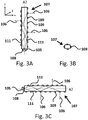
- Figs. 3a-3c schematically depict a more detailed view of the light guide of the lighting device of Fig. 1 in a Z direction ( Fig. 3a ), in a Y direction ( Fig. 3b ), and in a X direction ( Fig. 3c ) according to another embodiment of the present invention.
- the at least one light guide 107 has an elongated body and comprises at least one light in-coupling portion 108 at least on the external periphery of the at least one light guide 107 to couple light 106 into the at least one light guide 107.
- the at least one light guide 107 comprises a plurality of light out-coupling portions 109 to couple light 106 out of the at least one light guide 107 in a second spatial light distribution.
- the at least one light guide 107 is arranged for guiding the light 106 which is coupled into the at least one light guide 107 at the at least one light in-coupling portion 108 via total internal reflection 111 to the plurality of light out-coupling portions 109.
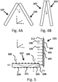
- Figs. 4a-4b schematically depict a cross-section of the LED-filament 103 and light guide 107 in a XY plane according to another embodiment of the present invention.
- the substrate 103 has an elongated body has an extension along a first elongation axis A1 and the at least one light guide 107 has an elongated body which has an extension along a second elongation axis A2.
- At least a portion of the first elongation axis A1 is non-parallel to at least a portion of the second elongation axis A2.
- the angle ⁇ between the first elongation axis A1 and the second elongation axis A2 is in the range from 10 to 80 degrees.
- the angle ⁇ between the first elongation axis A1 and the second elongation axis A2 is in the range from 10 to 30 degrees.
- Fig. 5 schematically depicts a more detailed cross-section of the LED-filament 103 and light guide 107 in a XY plane according to another embodiment. As depicted in Fig. 5 , at least part of the light 106 emitted by the plurality of light sources 105 is coupled into the at least one light guide 107.
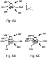
- Figs. 6a-6c schematically depict a more detailed cross-section of the LED-filament 103 and light guide 107 in a XZ plane according to another embodiment of the present invention.
- the at least one light guide 107 is mechanically and optically coupled to the at least one LED-filament 103.
- the at least one light guide 107 is mechanically and optically coupled to the at least one LED-filament 103.
- the LED-filament may be encapsulated by an encapsulant 116 such as, for example, a polymer material.
- the polymer material may be a silicone.
- the obtained effect is improved optical coupling.
- the reason is that the silicone improved the mechanical and optical coupling of the LED-filament 103 to the light guide 107.
- the encapsulant 116 may comprise a luminescent material such as an inorganic phosphor, an organic phosphor or quantum dots or rods.
- the luminescent material may for example be dispersed in the encapsulant 116.
- the at least one light guide 107 is mechanically and optically coupled to the at least one LED-filament 103.
- the light guide may, for example, be partly surrounded by the encapsulant 116.
- Figs. 7a-7d schematically depict a more detailed cross-section of the LED-filament 103 and light guide 107 in a XZ plane according to another embodiment of the present invention.
- the light guide 107 may comprise a scattering material 119, such as for example TiO2, BaSO4 and/or Al2O3 particles or air bubbles.
- the obtained effect is improved in-coupling of the light 106 into the light guide 107.
- the reason is that light 106 is redirected by the scattering material 119 such that light 106 is coupled into the light guide 107.
- the light guide 107 may comprise a reflector 120, such as for example a diffuse reflective material such as for example a material based on TiO2, BaSO4 and/or Al2O3 particles.
- a reflector 120 such as for example a diffuse reflective material such as for example a material based on TiO2, BaSO4 and/or Al2O3 particles.
- the light guide 107 may comprise a refractive structure 121.
- the obtained effect is improved in-coupling of the light 106 into the light guide 107.
- the reason is that light 106 is redirected by the refractive structure 121 such that light 106 is coupled into the light guide 107.
- the light guide 107 encapsulant 116 may be partly surrounded by the light guide comprise a refractive structure 121.
- the obtained effect is improved in-coupling of the light 106 into the light guide 107.
- the reason is that light 106 is redirected by the refractive structure 121 such that light 106 is coupled into the light guide 107.
- Figs. 7a-7d schematically depict a more detailed cross-section of the LED-filament 103 and light guide 107 which are mechanically and optically coupled.
- the LED-filament 103 and light guide 107 may also positioned at a distance different from zero from each other.
- Figs. 8 schematically depicts a more detailed cross-section of the LED-filament 103 and light guide 107 in a XY plane according to another embodiment of the present invention.
- the lighting device 100 comprises at least one further light source 114. At least part of the light 106 emitted by the at least one further light source 114 is coupled into the at least one light guide 107.
- the at least one further light source may be arranged on a further light source carrier.
- Figs. 9a-9d schematically depict a more detailed view of the LED-filament 103 and light guide 107 in a Z direction according to another embodiment of the present invention.
- the light guide 107 has a first portion and a second portion.
- the LED-filament 103 has a first portion and a second portion.
- the first portion of the light guide 107 is wrapped around the first portion of the LED-filament 103.
- the second portion of the light guide 107 is not wrapped around the LED-filament 103 and provides a decorative light emitting loop.
- the light guide 107 has a first portion and a second portion.
- the first LED-filament 103' has a first portion and a second portion.
- the second LED-filament 103" has a first portion and a second portion.
- the first portion of the light guide 107 is wrapped around the first portion of the first LED-filament 103.
- the second portion of the light guide 107 is wrapped around the first portion of the second LED-filament 103".
- the light guide 107 provides a decorative light emitting connection between the first LED-filament 103' and the second LED-filament 103".
- the light guide 107 is wrapped around a first LED-filament 103' and a second LED-filament 103".
- the light guide 107 provides a decorative light emitting connections between the first LED-filament 103' and the second LED-filament 103".
- Such configuration provides a decorative lighting effect integrating both types of filaments.
- the light guide 107 is wrapped around a first LED-filament 103' and a second LED-filament 103".
- the first LED-filament 103' is non-parallel to the second LED-filament 103".
- the light guide 107 provides a decorative light emitting connections between the first LED-filament 103' and the second LED-filament 103".
- Such configuration provides a decorative lighting effect integrating both types of filaments.
- multiple LED-filaments 103 may be combined with multiple light guides 107.
- two LED-filaments 103 may be combined with two light guides 107.
- two times the configuration shown in Fig. 9A may be used.
- At least a first portion of the at least one light guide 107 is mechanically and optically coupled to the a first portion of the at least one LED-filament 103, and at least a second portion of the at least one light guide 107 is mechanically and optically coupled to the a second portion of the at least one LED-filament 103.
- the average intensity of the at least one light guide 107 is in the range from 0.5 times the average intensity of the at least one LED-filament 103 and 2 times the average intensity of the at least one LED-filament 103. In this way the light guides 107 and the LED filaments 103 have about the same appearance.
- Fig. 10 schematically depicts a view of the lighting device 100 in a Z direction according to an embodiment of the present invention.
- the lighting device comprise a first LED-filament 103', a second LED-filament 103" and a light guide 107.
- the light guide 107 is positioned along the longitudinal axis LA and the first LED filament 103' and the second LED-filament 103" are positioned at non-zero distance to the light guide 107.
- the average diameter of the at least one light guide 107 is in range from 0.5 times the average diameter of the at least one LED-filament 103 and 2 times the average diameter of the at least one LED-filament 103. In this way the light guides 107 and the LED filaments 103 have about the same appearance.
- the total length of the at least one light guide 107 is at least 2 times the total length of the at least one at least one LED-filament 103.
- Fig. 11 schematically depicts a cross-section of the light guide 107 in a XY plane according to an embodiment of the present invention.
- the light guide 107 comprises a core 118 and a cladding 117.
- the cladding 117 is at least partly surrounding the core 118.
- the cladding 118 has a lower refractive index than the core 117.
- Light 106 is kept in the core 117 by the phenomenon of total internal reflection 111 which causes the light guide to act as a waveguide. The obtained effect is that light 106 can be guided along the length of the fiber and coupled out of the light guide 107 by the plurality of light out-coupling portions 109.
- the lighting device 100 comprises a control unit 115 electrically connected to the plurality of light sources 105 and at least one further light source 114 to separately control the amount of light 108 which is emitted from the plurality of light sources 105 and at least one further light source 114.
- the control unit 115 may control the amount of light 108 which is emitted from the plurality of light sources 105 and at least one further light source 114 based on input received from a user interface, a clock module and/or a sensor.
- the user interface may be, for example, a touch-display.
- the sensor may be, for example, a light sensor and/or a presence sensor.
- the control unit 115 may separately control the amount of light 108 which is emitted from the plurality of light sources 105 and at least one further light source 114. For example, if the sensor measures a low ambient light level the control unit 115 separately control the amount of light 108 which is emitted from the plurality of light sources 105 and at least one further light source 114 such that the at least one further light source 114 emits relatively more light than the plurality of light sources 105.
- the plurality of light sources 105 and/or at least one further light source 114 selected from the group consisting of phosphor converted light emitting diodes, direct emitting light emitting diodes, phosphor converted laser diodes, and direct emitting laser diodes.
- the lighting device 100 may be configured to provide white light.
- white light herein, is known to the person skilled in the art and relates to white light having a correlated color temperature (CCT) between about 2.000 K and 20.000 K.
- CCT correlated color temperature
- the CCT is between 2.500 K and 10.000K.
- the CCT is in the range of about 2700K to 6500K.
- it relates to white light having a color point within about 15, 10 or 5 SDCM (standard deviation of color matching) from the BBL (black body locus).
- BBL black body locus
- it relates to white light having a color rendering index (CRI) of at least 70 to 75, for general lighting at least 80 to 85.
- CRI color rendering index
- substantially herein, such as in “substantially all light” or in “substantially consists”, will be understood by the person skilled in the art.
- the term “substantially” may also include embodiments with “entirely”, “completely”, “all”, etc. Hence, in embodiments the adjective substantially may also be removed.
- the term “substantially” may also relate to 90% or higher, such as 95% or higher, especially 99% or higher, even more especially 99.5% or higher, including 100%.
- the term “comprise” includes also embodiments wherein the term “comprises” means “consists of'.
- the term “and/or” especially relates to one or more of the items mentioned before and after "and/or”.
- a phrase “item 1 and/or item 2" and similar phrases may relate to one or more of item 1 and item 2.
- the term “comprising” may in an embodiment refer to “consisting of' but may in another embodiment also refer to "containing at least the defined species and optionally one or more other species”.
Claims (14)
- Dispositif d'éclairage (100) destiné à être utilisé dans un luminaire (200) comprenant :- une base (101) ayant un axe longitudinal (LA) et comprenant un connecteur électrique (102) pour connecter le dispositif d'éclairage (100) à une douille de luminaire (201) du luminaire (200),- au moins un filament DEL (103) comprenant un substrat (104) ayant un corps allongé et une pluralité de sources lumineuses (105) couplées mécaniquement au substrat (104), la pluralité de sources lumineuses (105) étant configurées pour émettre une lumière (106) dans une première répartition lumineuse spatiale,- au moins un guide lumineux (107) ayant un corps allongé, comprenant au moins une portion de couplage d'entrée de lumière (108) au moins sur la périphérie externe de l'au moins un guide lumineux (107) pour coupler une lumière (106) dans l'au moins un guide lumineux (107), une pluralité de portions de couplage de sortie de lumière (109) pour coupler une lumière (106) sortant de l'au moins un guide lumineux (107) dans une seconde répartition lumineuse spatiale,- une enveloppe de transmission au moins partielle de lumière (110) renfermant au moins partiellement ledit au moins un filament DEL (103) et ledit au moins un guide lumineux (107),- dans lequel l'au moins un guide lumineux (107) est agencé pour guider la lumière (106) couplée dans l'au moins un guide lumineux (107) à l'au moins une portion de couplage d'entrée de lumière (108) via une réflexion interne totale (111) à la pluralité de portions de couplage de sortie de lumière (109),- dans lequel l'au moins un filament DEL (103) est à l'extérieur de l'au moins un guide lumineux (107)- dans lequel au moins une partie de la lumière (106) émise par la pluralité de sources lumineuses (105) est couplée dans l'au moins un guide lumineux (107), et- dans lequel le dispositif d'éclairage (100) comprend au moins une autre source lumineuse (114), dans lequel au moins une partie de la lumière (106) émise par l'au moins une autre source lumineuse (114) est couplée dans l'au moins un guide lumineux (107), caractérisé en ce que diamètre moyen de l'au moins un guide lumineux (107) est dans une plage de 0,5 fois le diamètre moyen de l'au moins un filament DEL (103) et 2 fois le diamètre moyen de l'au moins un filament DEL (103).
- Dispositif d'éclairage (100) selon la revendication 1, comprenant en outre un circuit d'attaque (113) connecté électriquement entre le connecteur électrique (102) et la pluralité de sources lumineuses (105).
- Dispositif d'éclairage (100) selon l'une quelconque des revendications précédentes, dans lequel le substrat (103) a un corps allongé ayant une extension le long d'un premier axe d'allongement (A1) et l'au moins un guide lumineux (107) a un corps allongé ayant une extension le long d'un second axe d'allongement (A2), dans lequel au moins une portion du premier axe d'allongement (A1) n'est pas parallèle à au moins une portion du second axe d'allongement (A2).
- Dispositif d'éclairage (100) selon l'une quelconque des revendications précédentes, dans lequel l'angle θ entre le premier axe d'allongement (A1) et le second axe d'allongement (A2) est dans la plage de 10 à 80 degrés.
- Dispositif d'éclairage (100) selon l'une quelconque des revendications 1 à 4, dans lequel l'angle θ entre le premier axe d'allongement (A1) et le second axe d'allongement (A2) est dans la plage de 10 à 30 degrés.
- Dispositif d'éclairage (100) selon l'une quelconque des revendications précédentes, dans lequel l'au moins un guide lumineux (107) est couplé mécaniquement et optiquement à l'au moins un filament DEL (103).
- Dispositif d'éclairage (100) selon l'une quelconque des revendications précédentes, dans lequel au moins une partie de l'au moins un guide lumineux (107) est enroulée autour de l'au moins un filament DEL (103).
- Dispositif d'éclairage (100) selon la revendication 7, dans lequel le guide lumineux (107) est en outre enroulé autour d'un second filament DEL (103").
- Dispositif d'éclairage (100) selon l'une quelconque des revendications précédentes, dans lequel l'intensité moyenne de l'au moins un guide lumineux (107) est dans la plage de 0,5 fois l'intensité moyenne de l'au moins un filament DEL (103) et 2 fois l'intensité moyenne de l'au moins un filament DEL (103).
- Dispositif d'éclairage (100) selon l'une quelconque des revendications précédentes, dans lequel l'au moins un guide lumineux (107) est positionné le long de l'axe longitudinal (LA) et l'au moins un filament DEL (103) est positionné à une distance non nulle de l'au moins un guide lumineux (107).
- Dispositif d'éclairage (100) selon l'une quelconque des revendications précédentes, dans lequel la longueur totale de l'au moins un guide lumineux (107) est au moins 2 fois la longueur totale de l'au moins un filament DEL (103).
- Dispositif d'éclairage (100) selon l'une quelconque des revendications précédentes ne renvoyant pas aux revendications 3 à 5, dans lequel au moins une première portion de l'au moins un guide lumineux (107) est couplée mécaniquement et optiquement à la première portion de l'au moins un filament DEL (103), et au moins une seconde portion de l'au moins un guide lumineux (107) est couplée mécaniquement et optiquement à la seconde portion de l'au moins un filament DEL (103).
- Dispositif d'éclairage (100) selon l'une quelconque des revendications précédentes, dans lequel le dispositif d'éclairage (100) comprend une unité de commande (115) connectée électriquement à la pluralité de sources lumineuses (105) et à l'au moins une autre source lumineuse (114) pour commander séparément la quantité de lumière (106) émise depuis la pluralité de sources lumineuses (105) et l'au moins une autre source lumineuse (114).
- Luminaire (200) comprenant ledit dispositif d'éclairage (100) selon l'une quelconque des revendications 1 à 13.
Applications Claiming Priority (2)
| Application Number | Priority Date | Filing Date | Title |
|---|---|---|---|
| EP17168998 | 2017-05-02 | ||
| PCT/EP2018/061039 WO2018202625A1 (fr) | 2017-05-02 | 2018-04-30 | Dispositif d'éclairage et luminaire |
Publications (2)
| Publication Number | Publication Date |
|---|---|
| EP3619460A1 EP3619460A1 (fr) | 2020-03-11 |
| EP3619460B1 true EP3619460B1 (fr) | 2021-03-24 |
Family
ID=58668761
Family Applications (1)
| Application Number | Title | Priority Date | Filing Date |
|---|---|---|---|
| EP18719216.6A Active EP3619460B1 (fr) | 2017-05-02 | 2018-04-30 | Dispositif d'éclairage et luminaire |
Country Status (5)
| Country | Link |
|---|---|
| US (1) | US11015765B2 (fr) |
| EP (1) | EP3619460B1 (fr) |
| JP (1) | JP7080253B2 (fr) |
| CN (1) | CN110573791B (fr) |
| WO (1) | WO2018202625A1 (fr) |
Families Citing this family (11)
| Publication number | Priority date | Publication date | Assignee | Title |
|---|---|---|---|---|
| CN113330245A (zh) * | 2019-01-24 | 2021-08-31 | 昕诺飞控股有限公司 | Led灯丝装置 |
| WO2020173743A1 (fr) * | 2019-02-28 | 2020-09-03 | Signify Holding B.V. | Lampe à filament avec réflecteur |
| WO2020207902A1 (fr) * | 2019-04-11 | 2020-10-15 | Signify Holding B.V. | Lampe à semi-conducteurs |
| EP4004432B1 (fr) * | 2019-07-26 | 2022-11-16 | Signify Holding B.V. | Agencement de filament à del |
| EP4007868A1 (fr) * | 2019-08-01 | 2022-06-08 | Signify Holding B.V. | Structure optique de production d'effets décoratifs d'éclairage |
| US11841115B2 (en) | 2019-10-03 | 2023-12-12 | Signify Holding B.V. | LED filament lighting device |
| CN211578697U (zh) * | 2020-01-15 | 2020-09-25 | 漳州立达信光电子科技有限公司 | 柔性灯丝灯 |
| WO2021249788A1 (fr) * | 2020-06-08 | 2021-12-16 | Signify Holding B.V. | Dispositif électroluminescent à effet scintillant |
| CN116134264A (zh) * | 2020-07-16 | 2023-05-16 | 昕诺飞控股有限公司 | 一种发光设备 |
| WO2022023241A1 (fr) | 2020-07-27 | 2022-02-03 | Signify Holding B.V. | Dispositif électroluminescent |
| CN117916638A (zh) * | 2021-09-06 | 2024-04-19 | 昕诺飞控股有限公司 | 发光设备 |
Family Cites Families (22)
| Publication number | Priority date | Publication date | Assignee | Title |
|---|---|---|---|---|
| PT4008949T (pt) | 2004-09-29 | 2024-02-21 | Signify Holding Bv | Dispositivo de iluminação |
| US8890401B2 (en) * | 2008-02-25 | 2014-11-18 | Illumination Machines, Llc | Solid-state luminescent filament lamps |
| KR101857776B1 (ko) | 2009-01-09 | 2018-05-15 | 필립스 라이팅 홀딩 비.브이. | Led, 광 가이드 및 반사기를 구비하는 광원 |
| US8750671B1 (en) * | 2009-04-16 | 2014-06-10 | Fusion Optix, Inc | Light bulb with omnidirectional output |
| BR112013015643A2 (pt) | 2010-12-22 | 2016-10-11 | Koninkl Philips Electronics Nv | dispositivo de iluminação para prover iluminação decorativa e método de fabricação de um dispositivo de iluminação para prover iluminação decorativa |
| EP2525134A1 (fr) | 2010-12-24 | 2012-11-21 | Panasonic Corporation | Lampe en forme d'ampoule et dispositif d'éclairage |
| JP2012146738A (ja) | 2011-01-07 | 2012-08-02 | Stanley Electric Co Ltd | Ledモジュール及びledランプ |
| CN109065676A (zh) * | 2011-08-08 | 2018-12-21 | 夸克星有限责任公司 | 包括多个发光元件的照明装置 |
| CN103975189A (zh) * | 2011-12-14 | 2014-08-06 | 通用电气照明解决方案有限责任公司 | Led灯上制造灯丝效果的侧发光导管技术 |
| JP2014110301A (ja) | 2012-11-30 | 2014-06-12 | Panasonic Corp | 発光装置および照明用光源 |
| US9677738B2 (en) * | 2013-03-15 | 2017-06-13 | 1947796 Ontario Inc. | Optical device and system for solid-state lighting |
| CN103712105A (zh) | 2013-12-26 | 2014-04-09 | 四川柏狮光电技术有限公司 | 一种扭纹状灯丝排布的全配光型led球泡灯 |
| US20170051877A1 (en) * | 2014-02-24 | 2017-02-23 | Philips Lighting Holding B.V. | Lamp assembly |
| CN108613029A (zh) | 2014-03-13 | 2018-10-02 | 飞利浦照明控股有限公司 | 用于照明装置的灯丝 |
| DE102014213388A1 (de) | 2014-07-09 | 2016-01-14 | Osram Gmbh | Halbleiterlampe |
| CN204254304U (zh) | 2014-09-24 | 2015-04-08 | 浙江承康机电制造有限公司 | 一种led灯 |
| JP2016066427A (ja) | 2014-09-24 | 2016-04-28 | 東芝ライテック株式会社 | 発光装置および照明器具 |
| EP3256774B1 (fr) * | 2015-02-12 | 2018-10-17 | Philips Lighting Holding B.V. | Module d'éclairage et dispositif d'éclairage le comprenant |
| CN106151934A (zh) * | 2015-04-20 | 2016-11-23 | 葛兰菲照明有限公司 | 整合照明及夜灯功能的led灯泡 |
| US9689560B2 (en) | 2015-06-05 | 2017-06-27 | Chung Ping Lai | LED light bulb simultaneously using as nightlight |
| GB2539190B (en) | 2015-06-05 | 2021-02-03 | Graphene Lighting Plc | An LED light bulb |
| CN205137115U (zh) * | 2015-11-03 | 2016-04-06 | 厦门多彩光电子科技有限公司 | 一种led灯丝灯 |
-
2018
- 2018-04-30 US US16/610,378 patent/US11015765B2/en active Active
- 2018-04-30 CN CN201880028651.8A patent/CN110573791B/zh active Active
- 2018-04-30 WO PCT/EP2018/061039 patent/WO2018202625A1/fr unknown
- 2018-04-30 EP EP18719216.6A patent/EP3619460B1/fr active Active
- 2018-04-30 JP JP2019560106A patent/JP7080253B2/ja active Active
Non-Patent Citations (1)
| Title |
|---|
| None * |
Also Published As
| Publication number | Publication date |
|---|---|
| JP2020518974A (ja) | 2020-06-25 |
| JP7080253B2 (ja) | 2022-06-03 |
| US11015765B2 (en) | 2021-05-25 |
| EP3619460A1 (fr) | 2020-03-11 |
| CN110573791A (zh) | 2019-12-13 |
| WO2018202625A1 (fr) | 2018-11-08 |
| CN110573791B (zh) | 2022-03-04 |
| US20200141541A1 (en) | 2020-05-07 |
Similar Documents
| Publication | Publication Date | Title |
|---|---|---|
| EP3619460B1 (fr) | Dispositif d'éclairage et luminaire | |
| KR101857776B1 (ko) | Led, 광 가이드 및 반사기를 구비하는 광원 | |
| JP5734204B2 (ja) | 光学要素及び当該光学要素を有する光源 | |
| US9097396B2 (en) | LED based lighting system | |
| EP2789894B1 (fr) | Dispositif d'éclairage | |
| KR101839417B1 (ko) | Led, 광 가이드 및 반사기를 구비하는 광원 | |
| US9057503B2 (en) | Light-emitting diode light bulb generating direct and decorative illumination | |
| US20220390074A1 (en) | Led filament and led filament lamp | |
| CN109716013A (zh) | 发光器件 | |
| EP3596386B1 (fr) | Module, système et procédé d'éclairage | |
| US11519563B2 (en) | Light-emitting device | |
| CN114423988B (zh) | Led灯丝灯 | |
| CN110914588A (zh) | 发光模块 | |
| JP6395033B2 (ja) | 照明装置 | |
| EP2662615A1 (fr) | Lampe et luminaire à ampoule |
Legal Events
| Date | Code | Title | Description |
|---|---|---|---|
| STAA | Information on the status of an ep patent application or granted ep patent |
Free format text: STATUS: UNKNOWN |
|
| STAA | Information on the status of an ep patent application or granted ep patent |
Free format text: STATUS: THE INTERNATIONAL PUBLICATION HAS BEEN MADE |
|
| PUAI | Public reference made under article 153(3) epc to a published international application that has entered the european phase |
Free format text: ORIGINAL CODE: 0009012 |
|
| STAA | Information on the status of an ep patent application or granted ep patent |
Free format text: STATUS: REQUEST FOR EXAMINATION WAS MADE |
|
| 17P | Request for examination filed |
Effective date: 20191202 |
|
| AK | Designated contracting states |
Kind code of ref document: A1 Designated state(s): AL AT BE BG CH CY CZ DE DK EE ES FI FR GB GR HR HU IE IS IT LI LT LU LV MC MK MT NL NO PL PT RO RS SE SI SK SM TR |
|
| AX | Request for extension of the european patent |
Extension state: BA ME |
|
| DAV | Request for validation of the european patent (deleted) | ||
| DAX | Request for extension of the european patent (deleted) | ||
| GRAJ | Information related to disapproval of communication of intention to grant by the applicant or resumption of examination proceedings by the epo deleted |
Free format text: ORIGINAL CODE: EPIDOSDIGR1 |
|
| GRAP | Despatch of communication of intention to grant a patent |
Free format text: ORIGINAL CODE: EPIDOSNIGR1 |
|
| GRAP | Despatch of communication of intention to grant a patent |
Free format text: ORIGINAL CODE: EPIDOSNIGR1 |
|
| STAA | Information on the status of an ep patent application or granted ep patent |
Free format text: STATUS: GRANT OF PATENT IS INTENDED |
|
| GRAJ | Information related to disapproval of communication of intention to grant by the applicant or resumption of examination proceedings by the epo deleted |
Free format text: ORIGINAL CODE: EPIDOSDIGR1 |
|
| GRAP | Despatch of communication of intention to grant a patent |
Free format text: ORIGINAL CODE: EPIDOSNIGR1 |
|
| STAA | Information on the status of an ep patent application or granted ep patent |
Free format text: STATUS: GRANT OF PATENT IS INTENDED |
|
| INTG | Intention to grant announced |
Effective date: 20201013 |
|
| INTG | Intention to grant announced |
Effective date: 20201022 |
|
| GRAS | Grant fee paid |
Free format text: ORIGINAL CODE: EPIDOSNIGR3 |
|
| GRAA | (expected) grant |
Free format text: ORIGINAL CODE: 0009210 |
|
| STAA | Information on the status of an ep patent application or granted ep patent |
Free format text: STATUS: THE PATENT HAS BEEN GRANTED |
|
| AK | Designated contracting states |
Kind code of ref document: B1 Designated state(s): AL AT BE BG CH CY CZ DE DK EE ES FI FR GB GR HR HU IE IS IT LI LT LU LV MC MK MT NL NO PL PT RO RS SE SI SK SM TR |
|
| REG | Reference to a national code |
Ref country code: GB Ref legal event code: FG4D |
|
| REG | Reference to a national code |
Ref country code: CH Ref legal event code: EP |
|
| REG | Reference to a national code |
Ref country code: IE Ref legal event code: FG4D |
|
| REG | Reference to a national code |
Ref country code: AT Ref legal event code: REF Ref document number: 1374826 Country of ref document: AT Kind code of ref document: T Effective date: 20210415 Ref country code: DE Ref legal event code: R096 Ref document number: 602018014388 Country of ref document: DE |
|
| REG | Reference to a national code |
Ref country code: SE Ref legal event code: TRGR |
|
| REG | Reference to a national code |
Ref country code: LT Ref legal event code: MG9D |
|
| PG25 | Lapsed in a contracting state [announced via postgrant information from national office to epo] |
Ref country code: NO Free format text: LAPSE BECAUSE OF FAILURE TO SUBMIT A TRANSLATION OF THE DESCRIPTION OR TO PAY THE FEE WITHIN THE PRESCRIBED TIME-LIMIT Effective date: 20210624 Ref country code: BG Free format text: LAPSE BECAUSE OF FAILURE TO SUBMIT A TRANSLATION OF THE DESCRIPTION OR TO PAY THE FEE WITHIN THE PRESCRIBED TIME-LIMIT Effective date: 20210624 Ref country code: HR Free format text: LAPSE BECAUSE OF FAILURE TO SUBMIT A TRANSLATION OF THE DESCRIPTION OR TO PAY THE FEE WITHIN THE PRESCRIBED TIME-LIMIT Effective date: 20210324 Ref country code: FI Free format text: LAPSE BECAUSE OF FAILURE TO SUBMIT A TRANSLATION OF THE DESCRIPTION OR TO PAY THE FEE WITHIN THE PRESCRIBED TIME-LIMIT Effective date: 20210324 Ref country code: GR Free format text: LAPSE BECAUSE OF FAILURE TO SUBMIT A TRANSLATION OF THE DESCRIPTION OR TO PAY THE FEE WITHIN THE PRESCRIBED TIME-LIMIT Effective date: 20210625 |
|
| PG25 | Lapsed in a contracting state [announced via postgrant information from national office to epo] |
Ref country code: LV Free format text: LAPSE BECAUSE OF FAILURE TO SUBMIT A TRANSLATION OF THE DESCRIPTION OR TO PAY THE FEE WITHIN THE PRESCRIBED TIME-LIMIT Effective date: 20210324 Ref country code: RS Free format text: LAPSE BECAUSE OF FAILURE TO SUBMIT A TRANSLATION OF THE DESCRIPTION OR TO PAY THE FEE WITHIN THE PRESCRIBED TIME-LIMIT Effective date: 20210324 |
|
| REG | Reference to a national code |
Ref country code: NL Ref legal event code: MP Effective date: 20210324 |
|
| REG | Reference to a national code |
Ref country code: AT Ref legal event code: MK05 Ref document number: 1374826 Country of ref document: AT Kind code of ref document: T Effective date: 20210324 |
|
| PG25 | Lapsed in a contracting state [announced via postgrant information from national office to epo] |
Ref country code: NL Free format text: LAPSE BECAUSE OF FAILURE TO SUBMIT A TRANSLATION OF THE DESCRIPTION OR TO PAY THE FEE WITHIN THE PRESCRIBED TIME-LIMIT Effective date: 20210324 |
|
| PG25 | Lapsed in a contracting state [announced via postgrant information from national office to epo] |
Ref country code: LT Free format text: LAPSE BECAUSE OF FAILURE TO SUBMIT A TRANSLATION OF THE DESCRIPTION OR TO PAY THE FEE WITHIN THE PRESCRIBED TIME-LIMIT Effective date: 20210324 Ref country code: EE Free format text: LAPSE BECAUSE OF FAILURE TO SUBMIT A TRANSLATION OF THE DESCRIPTION OR TO PAY THE FEE WITHIN THE PRESCRIBED TIME-LIMIT Effective date: 20210324 Ref country code: CZ Free format text: LAPSE BECAUSE OF FAILURE TO SUBMIT A TRANSLATION OF THE DESCRIPTION OR TO PAY THE FEE WITHIN THE PRESCRIBED TIME-LIMIT Effective date: 20210324 Ref country code: AT Free format text: LAPSE BECAUSE OF FAILURE TO SUBMIT A TRANSLATION OF THE DESCRIPTION OR TO PAY THE FEE WITHIN THE PRESCRIBED TIME-LIMIT Effective date: 20210324 Ref country code: SM Free format text: LAPSE BECAUSE OF FAILURE TO SUBMIT A TRANSLATION OF THE DESCRIPTION OR TO PAY THE FEE WITHIN THE PRESCRIBED TIME-LIMIT Effective date: 20210324 |
|
| PG25 | Lapsed in a contracting state [announced via postgrant information from national office to epo] |
Ref country code: PL Free format text: LAPSE BECAUSE OF FAILURE TO SUBMIT A TRANSLATION OF THE DESCRIPTION OR TO PAY THE FEE WITHIN THE PRESCRIBED TIME-LIMIT Effective date: 20210324 Ref country code: RO Free format text: LAPSE BECAUSE OF FAILURE TO SUBMIT A TRANSLATION OF THE DESCRIPTION OR TO PAY THE FEE WITHIN THE PRESCRIBED TIME-LIMIT Effective date: 20210324 Ref country code: PT Free format text: LAPSE BECAUSE OF FAILURE TO SUBMIT A TRANSLATION OF THE DESCRIPTION OR TO PAY THE FEE WITHIN THE PRESCRIBED TIME-LIMIT Effective date: 20210726 Ref country code: SK Free format text: LAPSE BECAUSE OF FAILURE TO SUBMIT A TRANSLATION OF THE DESCRIPTION OR TO PAY THE FEE WITHIN THE PRESCRIBED TIME-LIMIT Effective date: 20210324 Ref country code: IS Free format text: LAPSE BECAUSE OF FAILURE TO SUBMIT A TRANSLATION OF THE DESCRIPTION OR TO PAY THE FEE WITHIN THE PRESCRIBED TIME-LIMIT Effective date: 20210724 |
|
| PG25 | Lapsed in a contracting state [announced via postgrant information from national office to epo] |
Ref country code: LU Free format text: LAPSE BECAUSE OF NON-PAYMENT OF DUE FEES Effective date: 20210430 |
|
| REG | Reference to a national code |
Ref country code: DE Ref legal event code: R097 Ref document number: 602018014388 Country of ref document: DE |
|
| REG | Reference to a national code |
Ref country code: BE Ref legal event code: MM Effective date: 20210430 |
|
| PG25 | Lapsed in a contracting state [announced via postgrant information from national office to epo] |
Ref country code: ES Free format text: LAPSE BECAUSE OF FAILURE TO SUBMIT A TRANSLATION OF THE DESCRIPTION OR TO PAY THE FEE WITHIN THE PRESCRIBED TIME-LIMIT Effective date: 20210324 Ref country code: AL Free format text: LAPSE BECAUSE OF FAILURE TO SUBMIT A TRANSLATION OF THE DESCRIPTION OR TO PAY THE FEE WITHIN THE PRESCRIBED TIME-LIMIT Effective date: 20210324 Ref country code: DK Free format text: LAPSE BECAUSE OF FAILURE TO SUBMIT A TRANSLATION OF THE DESCRIPTION OR TO PAY THE FEE WITHIN THE PRESCRIBED TIME-LIMIT Effective date: 20210324 Ref country code: CH Free format text: LAPSE BECAUSE OF NON-PAYMENT OF DUE FEES Effective date: 20210430 Ref country code: MC Free format text: LAPSE BECAUSE OF FAILURE TO SUBMIT A TRANSLATION OF THE DESCRIPTION OR TO PAY THE FEE WITHIN THE PRESCRIBED TIME-LIMIT Effective date: 20210324 Ref country code: LI Free format text: LAPSE BECAUSE OF NON-PAYMENT OF DUE FEES Effective date: 20210430 |
|
| PLBE | No opposition filed within time limit |
Free format text: ORIGINAL CODE: 0009261 |
|
| STAA | Information on the status of an ep patent application or granted ep patent |
Free format text: STATUS: NO OPPOSITION FILED WITHIN TIME LIMIT |
|
| PG25 | Lapsed in a contracting state [announced via postgrant information from national office to epo] |
Ref country code: SI Free format text: LAPSE BECAUSE OF FAILURE TO SUBMIT A TRANSLATION OF THE DESCRIPTION OR TO PAY THE FEE WITHIN THE PRESCRIBED TIME-LIMIT Effective date: 20210324 |
|
| 26N | No opposition filed |
Effective date: 20220104 |
|
| PG25 | Lapsed in a contracting state [announced via postgrant information from national office to epo] |
Ref country code: IE Free format text: LAPSE BECAUSE OF NON-PAYMENT OF DUE FEES Effective date: 20210430 |
|
| PG25 | Lapsed in a contracting state [announced via postgrant information from national office to epo] |
Ref country code: IS Free format text: LAPSE BECAUSE OF FAILURE TO SUBMIT A TRANSLATION OF THE DESCRIPTION OR TO PAY THE FEE WITHIN THE PRESCRIBED TIME-LIMIT Effective date: 20210724 |
|
| PG25 | Lapsed in a contracting state [announced via postgrant information from national office to epo] |
Ref country code: BE Free format text: LAPSE BECAUSE OF NON-PAYMENT OF DUE FEES Effective date: 20210430 |
|
| PG25 | Lapsed in a contracting state [announced via postgrant information from national office to epo] |
Ref country code: IT Free format text: LAPSE BECAUSE OF FAILURE TO SUBMIT A TRANSLATION OF THE DESCRIPTION OR TO PAY THE FEE WITHIN THE PRESCRIBED TIME-LIMIT Effective date: 20210324 |
|
| P01 | Opt-out of the competence of the unified patent court (upc) registered |
Effective date: 20230425 |
|
| PG25 | Lapsed in a contracting state [announced via postgrant information from national office to epo] |
Ref country code: CY Free format text: LAPSE BECAUSE OF FAILURE TO SUBMIT A TRANSLATION OF THE DESCRIPTION OR TO PAY THE FEE WITHIN THE PRESCRIBED TIME-LIMIT Effective date: 20210324 |
|
| PG25 | Lapsed in a contracting state [announced via postgrant information from national office to epo] |
Ref country code: HU Free format text: LAPSE BECAUSE OF FAILURE TO SUBMIT A TRANSLATION OF THE DESCRIPTION OR TO PAY THE FEE WITHIN THE PRESCRIBED TIME-LIMIT; INVALID AB INITIO Effective date: 20180430 |
|
| PGFP | Annual fee paid to national office [announced via postgrant information from national office to epo] |
Ref country code: FR Payment date: 20230421 Year of fee payment: 6 Ref country code: DE Payment date: 20230627 Year of fee payment: 6 |
|
| PGFP | Annual fee paid to national office [announced via postgrant information from national office to epo] |
Ref country code: SE Payment date: 20230421 Year of fee payment: 6 |
|
| PGFP | Annual fee paid to national office [announced via postgrant information from national office to epo] |
Ref country code: GB Payment date: 20230418 Year of fee payment: 6 |
|
| PG25 | Lapsed in a contracting state [announced via postgrant information from national office to epo] |
Ref country code: MK Free format text: LAPSE BECAUSE OF FAILURE TO SUBMIT A TRANSLATION OF THE DESCRIPTION OR TO PAY THE FEE WITHIN THE PRESCRIBED TIME-LIMIT Effective date: 20210324 |