EP3619083B1 - Vorrichtung zum erfassen und messen von bremsstaub - Google Patents
Vorrichtung zum erfassen und messen von bremsstaub Download PDFInfo
- Publication number
- EP3619083B1 EP3619083B1 EP18720761.8A EP18720761A EP3619083B1 EP 3619083 B1 EP3619083 B1 EP 3619083B1 EP 18720761 A EP18720761 A EP 18720761A EP 3619083 B1 EP3619083 B1 EP 3619083B1
- Authority
- EP
- European Patent Office
- Prior art keywords
- brake
- measuring
- air duct
- exhaust air
- dust particles
- Prior art date
- Legal status (The legal status is an assumption and is not a legal conclusion. Google has not performed a legal analysis and makes no representation as to the accuracy of the status listed.)
- Active
Links
Images
Classifications
-
- B—PERFORMING OPERATIONS; TRANSPORTING
- B60—VEHICLES IN GENERAL
- B60T—VEHICLE BRAKE CONTROL SYSTEMS OR PARTS THEREOF; BRAKE CONTROL SYSTEMS OR PARTS THEREOF, IN GENERAL; ARRANGEMENT OF BRAKING ELEMENTS ON VEHICLES IN GENERAL; PORTABLE DEVICES FOR PREVENTING UNWANTED MOVEMENT OF VEHICLES; VEHICLE MODIFICATIONS TO FACILITATE COOLING OF BRAKES
- B60T17/00—Component parts, details, or accessories of power brake systems not covered by groups B60T8/00, B60T13/00 or B60T15/00, or presenting other characteristic features
- B60T17/18—Safety devices; Monitoring
- B60T17/22—Devices for monitoring or checking brake systems; Signal devices
-
- G—PHYSICS
- G01—MEASURING; TESTING
- G01N—INVESTIGATING OR ANALYSING MATERIALS BY DETERMINING THEIR CHEMICAL OR PHYSICAL PROPERTIES
- G01N15/00—Investigating characteristics of particles; Investigating permeability, pore-volume or surface-area of porous materials
- G01N15/02—Investigating particle size or size distribution
-
- G—PHYSICS
- G01—MEASURING; TESTING
- G01N—INVESTIGATING OR ANALYSING MATERIALS BY DETERMINING THEIR CHEMICAL OR PHYSICAL PROPERTIES
- G01N15/00—Investigating characteristics of particles; Investigating permeability, pore-volume or surface-area of porous materials
- G01N2015/0042—Investigating dispersion of solids
- G01N2015/0046—Investigating dispersion of solids in gas, e.g. smoke
Definitions
- the invention relates to a device for detecting and measuring brake dust and a brake test bench.
- brake dust can also lead to heavy soiling of the wheel rims, which at least has aesthetic disadvantages and can spoil the overall visual impression of a vehicle.
- Measuring devices are known to detect, quantify and determine the size of the above-mentioned brake dust particles.
- the invention is based on the object of providing an improved device for detecting and measuring brake dust.
- the device can be used at an early stage in the design of a vehicle's braking system.
- the measuring device for detecting brake dust works in conjunction with a dynamic brake test bench, where the brake to be tested is actuated, for example, with an electric brake actuator.
- the measuring device is part of the overall application and can therefore be operated as part of the brake test bench.
- the measurement of brake dust particles can be performed in real time with multiple readings per second.
- the appropriate measurement procedure for this purpose includes an automated program with defined load cycles, which are applied to the braking system in the brake test bench. This allows the brake dust particles to be reproducibly detected and measured in conjunction with the respective loads acting on the brake.
- the measuring point can be located in the exhaust air duct of a blower system, which generates a cooling air flow to cool the brakes during testing.
- the brake dust particles are then transported by the air flow through the exhaust air duct of the blower system to the actual measuring point.
- This measuring point is located at a defined location in the exhaust air duct. There, the particles are collected by the measuring system, e.g., via a hose, a heated hose, or a heated hose with cold air, and fed to the particle measuring device.
- the particle measuring device is capable of counting particles and determining their size and size distribution.
- This device can be a well-known device for measuring small or very fine particles, such as a device used in exhaust gas analysis, e.g., for measuring particles in diesel exhaust. Such devices are well-known and will therefore not be discussed in detail here.
- the particle measuring device can communicate with the brake test bench, allowing measurements to be synchronized with the brake test using load profiles. This allows the particle measuring device's measurement results to always be assigned to the respective brake loads on the brake test bench.
- the exhaust duct thus also functions as a dilution channel or tunnel. This prevents the formation of clumps or conglomerates of the brake dust particles, which could adversely affect the measurement result. would distort the results or significantly impair the reproducibility of the measurement.
- Measurement accuracy can thus be significantly improved by using an exhaust air duct that achieves a dilution effect.
- the exhaust air duct must therefore be designed to reliably achieve the desired dilution effect. Simply discharging the cooling air flow from the test chamber is therefore not sufficient. Rather, the exhaust air duct should be dimensioned to enable the dilution effect.
- the exhaust air duct is made of a non-corrosive, electrically conductive material. If necessary, the entire exhaust air duct must be heated to prevent particle clumping.
- the volume flow in the exhaust air duct can be measured using a suitable volume flow measuring device.
- the following measurement parameters may be of interest: air volume, kilometers driven (of the vehicle whose braking system is currently mounted on the test bench).
- the following measured values should be possible: number of particles per kilometer driven (simulated on the test bench) and particle size or size distribution in the respective measuring sections of the tested load cycle of the brake test.
- the brake dust measuring device can be fully integrated into the brake test bench and measure automatically within the framework of a dynamic, realistic load cycle.
- the invention accordingly relates to a device according to claim 1 for measuring and detecting brake dust particles which have been released from a brake, with a removal device for receiving brake dust particles, a particle measuring device for measuring the number and/or size of the brake dust particles, and with a conveying device for guiding and conveying the Brake dust particles from the sampling device to the particle measuring device.
- the sampling device is designed to capture and further transport the particles released by the brakes.
- the conveying device e.g., a hose carrying an air stream
- the conveying device is designed to transport the particles collected or captured by the sampling device to the particle measuring device. It can be appropriately designed and, for example, also include a heatable hose to prevent the particles from clumping.
- a brake mount may be provided for mounting a brake.
- the brake is held and secured in the mount for testing purposes and is not itself part of the measuring device. Rather, the brake is the test object to be examined using the device.
- the removal device can be designed such that it can be arranged in the area of a brake that can be installed in the brake mount, in particular in the area of a brake caliper of the brake.
- the brake is not part of the measuring device.
- the brake can be, for example, a widely known disc brake for a vehicle, with a brake disc and a brake caliper and brake disc that partially surround the brake disc.
- the brake can be installed in the brake mount for testing purposes.
- the sampling device can have a collection container for collecting the brake dust particles.
- the collection container can be made of a non-corrosive, electrically conductive material. Additional instruments can be arranged near the sampling point or collection container, where the sampling device collects the brake dust, for example, to determine the particle mass, particle size distribution, etc.
- the brake mount is enclosed in a housing impermeable to brake dust particles, defining a brake mount space.
- the brake is then mounted in the brake mount within the brake mount space and can be tested.
- the housing surrounds the brake housing and can be made of a non-corrosive, electrically conductive material.
- the housing is The enclosure is sealed from the environment so that only air can be supplied to a blower system via an air supply duct described below. Furthermore, the enclosure allows the brake dust particles emitted during testing to be completely captured. However, the enclosure does not serve to dilute or homogenize the brake emissions; rather, these processes take place in the exhaust air duct, as previously described.
- a blower system is provided with an air supply duct and an exhaust duct for guiding an air flow over the brake.
- the air supply duct and the exhaust duct are coupled to the housing and thus each connected to the brake receiving space, for guiding an air flow through the brake receiving space.
- the openings of the air supply duct (outlet opening of the air supply duct on the housing) and the exhaust duct (inlet opening of the exhaust duct on the housing) to the brake receiving space are arranged opposite one another in the housing.
- the openings can be designed such that their respective opening cross-section allows the air flow to flow through the entire brake receiving space in the housing.
- the brake receiving space can be positioned such that a brake mounted on it is arranged between the outlet opening of the air supply duct and the inlet opening of the exhaust duct.
- the exhaust air duct is dimensioned such that its free diameter at its inlet opening on the housing is no less than 70% of the diameter of the brake disc to be tested. This ensures that the air flow fully encompasses the brake and removes all brake emissions through the inlet opening of the exhaust air duct.
- the air flow guides the brake dust particles so that they can be reliably captured by the extraction device in the exhaust air duct after they have flowed through a specific flow path of a specific length in the exhaust air duct.
- the air flow can also be used to cool the brakes.
- the distance between the inlet opening of the exhaust air duct and the extraction device can be at least 5 times, in particular at least 10 times or at least 20 times the diameter or the largest diagonal of the cross-section of the exhaust air duct, in particular the cross-section of the exhaust air duct downstream of the inlet opening.
- a possible funnel shape The inlet opening and the resulting expansion of the cross-section at the inlet are not taken into account in this calculation; the distance is determined by the dimensions of the exhaust air duct, which has a substantially constant cross-section over a certain section. If the exhaust air duct has a rectangular cross-section, the largest edge length of the rectangle can also be used as a parameter, for which the aforementioned conditions then apply. This ensures that the exhaust air duct has a certain length in order to achieve the desired dilution effect.
- the length of the exhaust air duct from its inlet opening to the extraction device can be at least 100 cm or at least 200 cm.
- the distance can also be understood in particular as the length of a virtual connecting line of the respective centroids of the cross-sectional areas in the exhaust air duct from the inlet opening to the extraction device.
- the extraction device can therefore be arranged in the exhaust air duct such that the flow path of the air stream from the brake to the extraction device has a predetermined length.
- the length of the flow path of the air stream and thus the distance between the axis of rotation of the brake and the extraction device depends on the size of the cross-section of the exhaust air duct.
- the invention therefore relates in particular to a device for measuring and detecting brake dust particles released from a brake, comprising a sampling device for receiving brake dust particles, a particle measuring device for measuring the number and/or size of the brake dust particles, and a conveying device for guiding and conveying the brake dust particles from the sampling device to the particle measuring device.
- the sampling device is arranged in the exhaust air duct, the opening of which is located in the housing of the brake receiving space.
- the brake to be tested is surrounded by this housing for the purpose of brake dust particle measurement and can be supplied with a cooling air flow from an air supply duct through the opening in the housing on a side opposite the exhaust air duct.
- the direction of the airflow can be selected as appropriate.
- the airflow can be directed from top to bottom, from bottom to top, or in other directions.
- the air flow can be made uniform by flow guide elements arranged in the supply air duct in order to achieve a homogeneous mixture of brake dust particles with (dilution) air.
- the blower system can also include an air conditioning system, e.g., with inlet filters for cleaning the air supplied via the supply air duct and for conditioning the air with respect to temperature and humidity.
- Flow straighteners can also be provided. At least the flow velocity of the air in the exhaust air duct can be controlled. Conditioning the air ensures that the test conditions for the brake can be largely standardized and reproduced.
- the combination of the enclosure and the extraction device provided in the exhaust air duct enables complete capture of all particles that have been released from the brake during measurement or testing operations.
- the particle measuring device can also be used for exhaust gas analysis, particularly for measuring particles in diesel exhaust. This allows a device already available on the test bench, for example, for testing combustion engines, especially diesel engines, to also be used for measuring brake dust.
- the particle measurement can be integrated into the automation software for a brake load device (e.g., a dynamometer). However, it can also be provided separately from the automation software or at least operate without integration into the dynamometer's automation. Synchronizing the particle measurement with the operation of the brake load device is advisable, however.
- a brake load device e.g., a dynamometer
- the conveying device can have one or more pipe- or hose-like lines, which can also be heated if required.
- a line can connect the sampling device to the particle measuring device.
- a brake test bench is specified, with a brake holder for holding a brake to be tested, a drive device for applying a braking load to the brake, measuring devices for recording test and measurement parameters of the brake, and with a device for determining brake dust particles, as specified above.
- the brake test and measurement parameters can be those typically relevant for brake testing. These include the drive power of the drive device, the braking power, the brake support torque, the speed, the braking force, the temperature development, vibrations, etc.
- the brake dust particle measuring device can be an integral part of the brake tester, meaning it can be installed together with the brake tester. This ensures that the device is always available during testing.
- the measurement results from the particle measurement system and the brake test and measurement parameters can be correlated, i.e., linked to one another. For example, it is possible to record which particle quantity is produced during each test operation. This allows, for example, a correlation to be established and documented between braking performance, speed, temperature, and particle quantity or size.
- An appropriate evaluation device can be provided for correlating the measurement results and parameters.
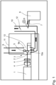
- the single figure schematically shows an embodiment of a device for detecting and measuring brake dust particles, which is intended as an integral component of a brake test bench.
- the brake test bench is designed as a flywheel brake test bench and is shown in the figure in a schematic view.
- a motor 1 e.g. an electric motor, serving as a prime mover, drives a brake disc 2 inserted in the brake test bench, which is part of the brake 3 to be tested.
- flywheel masses 4 can be integrated in a known manner.
- the brake disc 2 is partially enclosed in a known manner by a brake caliper 5, which also belongs to the brake 3 to be tested.
- the brake caliper 5 supports the brake pads (not shown in the figure), which are subject to wear when the brake 3 is applied, causing the (fine) particles to be detected to be released from the brake pads.
- Brake 3 is installed in the brake test bench in a brake mount (not shown), which supports the brake and its components and ensures stable support of the braking torque.
- a brake mount (not shown), which supports the brake and its components and ensures stable support of the braking torque.
- the design of such a brake mount in brake test benches is well known, so further description is unnecessary.
- a blower system comprising an air supply duct 9 with an outlet opening 9a and an exhaust duct 10 with an inlet opening 10a.
- the air supply duct 9 directs air through its outlet opening 9a into a housing 11 that encloses the brake 3 serving as the test specimen and is impermeable to brake dust particles.
- the exhaust duct 10 discharges this air from the housing 11 through its inlet opening 10a.
- the housing 11 thus encloses a brake receiving chamber 13.
- a measuring point for air volume flow measurement is provided in the exhaust air duct 10, e.g. at reference number 12.
- the fan system is usually present on brake test benches to ensure good ventilation of the brake, especially for cooling purposes.
- the air supplied via the supply air duct 9 can be conditioned in the desired manner with regard to temperature, humidity and purity (e.g. by means of a filter) by an air conditioning device (not shown) in order to achieve reproducible test results.
- the brake dust or brake dust particles are guided via the exhaust air duct 10 to the actual measuring point (at A), which is located in the exhaust air duct 10 and at which the sampling device 6 is provided. There, the particles are collected and guided, for example, via a heated hose 7 to the particle measuring device 8.
- the particle measuring device 8 can be a known device This could be a type of particle size analyzer, such as that used in exhaust gas measurement.
- the particle size analyzer 8 measures the number and size of particles.
Landscapes
- Chemical & Material Sciences (AREA)
- Analytical Chemistry (AREA)
- General Physics & Mathematics (AREA)
- Pathology (AREA)
- Dispersion Chemistry (AREA)
- Physics & Mathematics (AREA)
- Health & Medical Sciences (AREA)
- Immunology (AREA)
- Biochemistry (AREA)
- Life Sciences & Earth Sciences (AREA)
- General Health & Medical Sciences (AREA)
- Engineering & Computer Science (AREA)
- Mechanical Engineering (AREA)
- Transportation (AREA)
- Sampling And Sample Adjustment (AREA)
- Braking Arrangements (AREA)
Description
- Die Erfindung betrifft eine Vorrichtung zum Erfassen und Messen von Bremsstaub sowie einen Bremsenprüfstand.
- Die Umweltbelastung durch Fahrzeugbremsen, insbesondere von Kraftfahrzeug- oder LKW-Bremsen ist ein ernst zu nehmendes Thema. Durch den Bremsvorgang im Fahrzeug wird die Belagmasse der Bremsbeläge derart abgerieben, dass durch diesen Vorgang feinste Partikel losgelöst werden. Diese sind teilweise sogar lungengängig und leisten somit einen schädlichen Beitrag zur Feinstaubbelastung mit entsprechenden Risiken für gesundheitliche Beeinträchtigungen.
- Aber auch losgelöst von den ernsten Fragen einer Gesundheitsbeeinträchtigung durch Bremsen-Feinstaub kann Bremsstaub auch zu einer starken Verschmutzung der Radfelgen führen, was zumindest ästhetische Nachteile nach sich zieht und den optischen Gesamteindruck eines Fahrzeugs stören kann.
- Es sind Messvorrichtungen bekannt, um die o.g. Bremsstaub-Partikel zu erfassen, zu quantifizieren und deren Größe zu bestimmen.
- In den Veröffentlichungen
- Klaus Augsburg: "Sampling of Brake Dust Particles", 15. Juni 2016 (2016-06-15), URL:http://2016.eurobrake.net/, [gefunden am 2020-10-02];
- S. Gramstat, A Cserhati, M. Schroeder, Dmytro Lugovyy: "Brake Particle Emission Measurements - Testing Method and results", 28. März 2017 (2017-03-28), URL:http://2016.eurobrake.net/, [gefunden am 2020-10-02];
- H. Sachse, K. Augsburg: "XXXIV Internationales [My]- Symposium Bremsen-Fachtagung : October 30th to 31st 2015, Bad Neuenahr, Germany", 31. Oktober 2015 (2015-10-31)ISBN: 9783183794126;
- Carsten Trautmann: "Erstellen eines Messprozesses zur Partikelmessung von Bremsstaub", 2. Oktober 2013 (2013-10-02), Technische Universität Ilmenau;
- sind verschiedene Messvorrichtungen und Messverfahren zur Partikelmessung von Bremsstaub für die Bewertung bremseninduzierter Emissionen beschrieben. Zur Verbesserung der Qualität der Messergebnisse ist es anzustreben, dass möglichst viele bzw. alle Bremsstaub-Partikel erfasst werden können, die sich bei einem Bremsvorgang gelöst haben.
- Der Erfindung liegt die Aufgabe zugrunde, eine verbesserte Vorrichtung zum Erfassen und Messen von Bremsstaub anzugeben.
- Die Erfindung wird durch eine Vorrichtung mit den Merkmalen von Anspruch 1 gelöst. Vorteilhafte Weiterentwicklungen sind den abhängigen Ansprüchen zu entnehmen.
- Es ist vorteilhaft, wenn die Vorrichtung schon frühzeitig im Rahmen der Auslegung der Bremsanlage eines Fahrzeuges zur Anwendung kommen kann.
- Daher wird eine Messvorrichtung angegeben, welche in der üblichen, bekannten Prüf- und Entwicklungsumgebung für Bremssysteme Anwendung findet.
- Die Messvorrichtung für die Erfassung des Bremsstaubs funktioniert im Zusammenhang mit einem dynamischen Bremsenprüfstand, bei dem die zu prüfende Bremse z.B. mit einem beispielsweise elektrischen Bremsaktuator betätigt wird. Die Messvorrichtung ist in diesem Fall ein Teil der Gesamtapplikation und kann somit als Teil des Bremsenprüfstands betrieben werden. Die Messung der Bremsstaub-Partikel kann in Echtzeit mit mehreren Messwerten pro Sekunde erfolgen.
- Die dazu zweckmäßige Messprozedur umfasst ein automatisiertes Programm mit definierten Lastzyklen, mit welchen das Bremssystem im Bremsenprüfstand beaufschlagt wird. So können reproduzierbar in Verbindung mit den jeweils auf die Bremse wirkenden Lasten die Bremsstaubpartikel erfasst und gemessen werden.
- Das Partikelverhalten einer Bremse kann somit auf einem Bremsenprüfstand gemessen werden. Bremsenprüfstände werden benutzt, um die realen Lastprofile eines Bremssystems zu simulieren. Diese Prüfstände stellen in der Regel eine stabile, reproduzierbare Messumgebung zur Bremsenprüfung zur Verfügung.
- Zur Erfassung und Messung der Bremspartikel am Bremsenprüfstand ist es möglich, einen Messpunkt zu definieren. Der Messpunkt kann sich im Abluftkanal einer Gebläseanlage befinden, die zur Kühlung der Bremse im Prüfbetrieb einen Kühlluftstrom erzeugt. Die Bremsstaub-Partikel werden dann durch den Luftstrom über den Abluftkanal der Gebläseanlage zur eigentlichen Messstelle transportiert. Diese Messstelle befindet sich an einer definierten Stelle im Abluftkanal. Dort werden die Partikel vom Messsystem aufgenommen, z.B. über einen Schlauch, einen beheizten Schlauch oder einen beheizten Schlauch mit Kaltluft und zum Partikelmessgerät geführt.
- Das Partikelmessgerät ist in der Lage, die Partikel zu zählen und deren Größe bzw. Größenverteilung zu bestimmen. Bei dem Gerät kann es sich um ein an sich bekanntes Gerät zum Messen von kleinen bzw. feinsten Partikeln handeln, z.B. um ein Gerät, das bei der Abgasanalyse eingesetzt wird, z.B. zum Messen von Partikeln in Dieselabgasen. Derartige Geräte sind bekannt und werden daher an dieser Stelle nicht weiter vertieft.
- Das Partikelmessgerät kann mit dem Bremsenprüfstand kommunizieren, so dass die Messungen synchronisiert zur Bremsenprüfung mit Lastprofilen ablaufen. Auf diese Weise können die Messergebnisse des Partikelmessgeräts auch immer den jeweiligen Belastungen der Bremse im Bremsenprüfstand zugeordnet werden.
- Durch den Transport der Bremsemissionen, insbesondere der Bremspartikel, mit dem Kühlluftstrom des Abluftkanals werden diese verdünnt wobei zeitgleich eine homogene Mischung entsteht. Der Abluftkanal erfüllt die damit auch die Funktion eines Verdünnungskanals bzw. -tunnels. Dadurch wird die Bildung von Verklumpungen oder Konglomeraten der Bremsstaub-Partikel verhindert, die das Messergebnis verfälschen würden bzw. die Reproduzierbarkeit der Messung deutlich verschlechtern würden.
- Die Messgenauigkeit kann durch den eine Verdünnungswirkung erzielenden Abluftkanal somit erheblich verbessert werden. Der Abluftkanal ist demnach derart auszugestalten, dass er die gewünschte Verdünnungswirkung zuverlässig erreichen kann. Ein simples Abführen des Kühlluftstroms aus der Prüfkammer ist somit nicht ausreichend. Vielmehr sollte der Abluftkanal eine Dimensionierung aufweisen, die die Verdünnungswirkung ermöglicht.
- Erfindungsgemäß besteht der Abluftkanal aus einem nicht korrosiven, elektrisch leitenden Material. Gegebenenfalls ist der gesamte Abluftkanal zu beheizen, um eine Konglomerat-Bildung der Partikel zu verhindern.
- Der Volumenstrom im Abluftkanal kann mit einer geeigneten Volumenstrom-Messeinrichtung gemessen werden.
- Zusammen mit der Messung der Partikel (Anzahl, Größe) können folgende Messparameter von Interesse sein: Luftmenge, gefahrene Kilometer (des Fahrzeugs, dessen Bremssystem gerade auf dem Prüfstand montiert ist).
- Weitere Parameter wie Bremsdruck, Bremsmoment, Geschwindigkeit und weitere Parameter werden durch den eigentlichen Prüfstand erfasst und mit der Partikelmessung synchronisiert.
- Nach einer Messung soll die folgende Messwertangabe möglich sein: Partikelanzahl pro (auf dem Prüfstand simuliert) gefahrene Kilometer und Partikelgröße bzw. Größenverteilung in den jeweiligen Messabschnitten des getesteten Lastzyklus der Bremsenprüfung.
- Auf diese Weise kann die Bremsstaub-Messvorrichtung vollständig in den Bremsenprüfstand integriert werden und im Rahmen eines dynamischen, realitätsnahen Lastzyklus automatisiert messen.
- Die Erfindung betrifft demnach eine Vorrichtung nach Anspruch 1 zum Messen und Erfassen von Bremsstaub-Partikeln, die aus einer Bremse herausgelöst wurden, mit einer Entnahmeeinrichtung zum Aufnehmen von Bremsstaub-Partikeln, einer Partikel-Messeinrichtung zum Messen der Anzahl und/oder der Größe der Bremsstaub-Partikel, und mit einer Fördereinrichtung zum Führen und Fördern der Bremsstaub-Partikel von der Entnahmeeinrichtung zu der Partikel-Messeinrichtung. Die Entnahmeeinrichtung ist geeignet, die von der Bremse abgegebenen Partikel einzufangen und weiter zu transportieren.
- Die Fördereinrichtung, z.B. ein Schlauch, in dem ein Luftstrom geführt wird, ist geeignet, die von der Entnahmeeinrichtung gesammelten bzw. eingefangenen Partikel zu der Partikel-Messeinrichtung zu transportieren. Sie kann sinnvoll ausgebildet sein und z.B. auch einen beheizbaren Schlauch aufweisen, um eine Verklumpung der Partikel zu verhindern.
- Es kann eine Bremsenaufnahme zum Aufnehmen einer Bremse vorgesehen sein. Die Bremse wird in der Bremsenaufnahme für Prüfzwecke gehalten und befestigt und ist selbst nicht Teil der Messvorrichtung. Vielmehr ist die Bremse der Prüfling, der mithilfe der Vorrichtung untersucht werden soll.
- Die Entnahmeeinrichtung kann derart ausgebildet sein, dass sie im Bereich einer in der Bremsenaufnahme aufbaubaren Bremse anordenbar ist, insbesondere im Bereich eines Bremssattels der Bremse. Die Bremse ist dabei - wie oben ausgeführt - nicht Gegenstand der Messvorrichtung. Bei der Bremse kann es sich z.B. um eine an sich vielfach bekannte Scheibenbremse für ein Fahrzeug handeln, mit einer Bremsschreibe und einem die Bremsscheibe teilweise umgreifenden Bremssattel und Bremsscheibe. Die Bremse ist in Bremsenaufnahme für die Prüfzwecke aufbaubar.
- Die Entnahmeeinrichtung kann einen Sammelbehälter aufweisen, mit dem die Bremsstaub-Partikel aufgefangen werden können. Der Sammelbehälter kann aus einem nicht korrosiven, elektrisch leitenden Material bestehen. In der Nähe der Entnahmestelle bzw. des Sammelbehälters, an der die Entnahmeeinrichtung den Bremsstaub aufnimmt, können noch weitere Instrumente angeordnet sein, die z.B. der Bestimmung der Partikelmasse, der Partikelgrößen-Verteilung etc. dienen können.
- Die Bremsenaufnahme ist von einer für Bremsstaub-Partikel undurchlässigen Einhausung umschlossen, wodurch ein Bremsenaufnahmeraum definiert wird. Die Bremse ist dann innerhalb des Bremsenaufnahmeraums in der Bremsenaufnahme befestigt und kann geprüft werden.
- Die Einhausung umgibt den Bremsenaufnahmeraum und kann aus einem nicht korrosiven, elektrisch leitenden Material bestehen. Die Einhausung ist gegenüber der Umgebung abgedichtet, so dass ausschließlich Luft über einen nachfolgend beschriebenen Zuluftkanal einer Gebläseanlage zugeführt werden kann. Desweiteren ermöglicht es die Einhausung, dass die im Prüfbetrieb emittierten Bremsstaub-Partikel vollständig erfasst. Die Einhausung dient jedoch nicht zum Verdünnen oder Homogenisieren der Bremsemissionen, diese Vorgänge finden vielmehr wie zuvor geschildert im Abluftkanal statt.
- Es ist demnach eine Gebläseanlage vorgesehen, mit einem Zuluftkanal und einem Abluftkanal, um einen Luftstrom über die Bremse zu führen. Insbesondere sind der Zuluftkanal und der Abluftkanal an die Einhausung angekoppelt und damit jeweils mit dem Bremsenaufnahmeraum verbunden, zum Führen eines Luftstroms durch den Bremsenaufnahmeraum. Erfindungsgemäß sind die Öffnungen von Zuluftkanal (Auslassöffnung des Zuluftkanals an der Einhausung) und Abluftkanal (Einlassöffnung des Abluftkanals an der Einhausung) zum Bremsenaufnahmeraum in der Einhausung gegenüberliegend angeordnet. Die Öffnungen können derart gestaltet sein, dass ihr jeweiliger Öffnungsquerschnitt es dem Luftstrom erlaubt, den gesamten Bremsenaufnahmeraum in der Einhausung zu durchströmen. Die Bremsaufnahme ist kann derart positioniert seine, dass eine auf ihr aufgebaute Bremse zwischen der Auslassöffnung des Zuluftkanals und der Einlassöffnung des Abluftkanals angeordnet ist.
- Die Querschnitte des Zuluftkanals und des Abluftkanals sind dementsprechend groß zu definieren. Erfindungsgemäß ist der Abluftkanal derart dimensioniert, dass sein freier Durchmesser an seiner Einlassöffnung an der Einhausung nicht kleiner als 70% des Durchmessers der zu prüfenden Bremsscheibe ist. Damit kann erreicht werden, dass der Luftstrom die Bremse voll erfasst und sämtliche Bremsemissionen durch die Einlassöffnung des Abluftkanals abführt.
- Der Luftstrom dient zum Führen der Bremsstaub-Partikel, so dass die Bremsstaub-Partikel zuverlässig durch die Entnahmeeinrichtung im Abluftkanal erfasst werden können, nachdem die Bremsstaub-Partikel einen bestimmten Strömungsweg im Abluftkanal mit einer bestimmten Länge durchströmt haben. Ebenso kann der Luftstrom auch zum Kühlen der Bremse genutzt werden.
- Der Abstand zwischen der Einlassöffnung des Abluftkanals und der Entnahmeeinrichtung kann wenigstens dem 5-fachen, insbesondere wenigstens dem 10-fachen bzw. wenigstens dem 20-fachen des Durchmessers oder der größten Diagonalen des Querschnitts des Abluftkanals, insbesondere des Querschnitts des Abluftkanals stromab von der Einlassöffnung entsprechen. Eine eventuelle Trichterform der Einlassöffnung und damit Erweiterung des Querschnitts am Einlass bleibt bei dieser Berechnung unberücksichtigt; der Abstand bestimmt sich durch die Dimension des nachfolgend über einen bestimmten Abschnitt einen im Wesentlichen konstanten Querschnitt aufweisenden Abluftkanal. Wenn der Abluftkanal einen rechteckigen Querschnitt aufweist, kann als Parameter auch die größte Kantenlänge des Rechtecks herangezogen werden, für die dann die vorgenannten Bedingungen gelten. Damit ist gewährleistet, dass der Abluftkanal eine gewisse Länge aufweist, um die gewünschte Verdünnungswirkung zu erzielen. So kann die Länge des Abluftkanals von seiner Einlassöffnung bis zur Entnahmeeinrichtung z.B. wenigstens 100 cm oder wenigstens 200 cm betragen.
- Der Abstand kann insbesondere auch verstanden werden als die Länge einer virtuellen Verbindungslinie der jeweiligen Flächenschwerpunkte der Querschnittsflächen im Abluftkanal von der Einlassöffnung bis zur Entnahmeeinrichtung.
- Die Entnahmeeinrichtung kann demnach derart in dem Abluftkanal angeordnet sein, dass der Strömungsweg des Luftstroms von der Bremse bis zu der Entnahmeeinrichtung eine vorgegebene Länge aufweist. Erfindungsgemäß ist die Länge des Strömungswegs des Luftstroms und damit der Abstand zwischen der Drehachse der Bremse und der Entnahmeeinrichtung von der Größe des Querschnitts des Abluftkanals abhängig sein.
- Die Erfindung betrifft demnach insbesondere eine Vorrichtung zum Messen und Erfassen von Bremsstaub-Partikeln, die aus einer Bremse herausgelöst wurden, mit einer Entnahmeeinrichtung zum Aufnehmen von Bremsstaub-Partikeln, einer Partikel-Messeinrichtung zum Messen der Anzahl und/oder der Größe der Bremsstaub-Partikel, und mit einer Fördereinrichtung zum Führen und Fördern der Bremsstaub-Partikel von der Entnahmeeinrichtung zu der Partikel-Messeinrichtung. Die Entnahmeeinrichtung ist zu diesem Zweck im Abluftkanal angeordnet, dessen Öffnung sich in der Einhausung des Bremsenaufnahmeraumes befindet. Die zu prüfende Bremse ist zum Zwecke der Bremsstaub-Partikel Messung von dieser Einhausung umgeben und kann an einer gegenüberliegenden Seite zum Abluftkanal mit einem Kühlluftstrom aus einem Zuluftkanal durch die Öffnung in der Einhausung versorgt werden.
- Die Strömungsrichtung des Luftstroms kann in geeigneter Weise gewählt werden. So kann die Luftströmung von oben nach unten oder von unten nach oben oder auch in anderer Weise gerichtet sein.
- Die Luftströmung kann durch im Zuluftkanal angeordnete Stromführungselemente vergleichmäßigt werden, um eine homogene Mischung von Bremsstaub-Partikeln mit (Verdünnungs-)Luft zu erreichen.
- Die Gebläseanlage kann zusätzlich eine Luftkonditionierungsanlage aufweisen, z.B. mit Einlassfiltern zum Reinigen der über den Zuluftkanal zugeführten Luft und zum Konditionieren der Luft hinsichtlich Temperatur und Feuchtigkeit. Weiterhin können Strömungsgleichrichter vorgesehen sein. Zumindest bezüglich der Luftströmung im Abluftkanal kann die Strömungsgeschwindigkeit steuerbar sein. Durch das Konditionieren der Luft wird erreicht, dass die Prüfbedingungen für die Bremse weitgehend standardisiert und reproduziert werden können.
- Durch die Kombination aus der Einhausung und der im Abluftkanal vorgesehenen Entnahmeeinrichtung ist eine vollständige Erfassung sämtlicher Partikel möglich, die sich aus der Bremse während des Mess- bzw. Prüfbetriebs gelöst haben.
- Die Partikel-Messeinrichtung kann außer zum Messen der Bremsstaub-Partikel auch zur Abgasanalyse geeignet sein, insbesondere zum Messen von Partikeln in Dieselabgasen. Damit kann ein am Prüfstand z.B. für die Prüfung von Verbrennungsmotoren, insbesondere Dieselmotoren schon vorhandenes Gerät auch für die Messung von Bremsstaub genutzt werden.
- Die Partikel-Messeinrichtung kann z.B. einen Messbereich von D50 = 10 nm - 2.500 nm aufweisen.
- Die Partikelmessung kann dabei in die Automatisierungssoftware für eine Bremsen-Lasteinrichtung (z.B. einem Dynamometer) integriert sein. Sie kann aber auch separat zu der Automatisierungssoftware vorgesehen sein bzw. zumindest ohne eine Integrierung in die Automatisierung des Dynamometers arbeiten. Eine Synchronisation der Partikelmessung mit dem Betrieb der Bremsen-Lasteinrichtung ist aber zweckmäßig.
- Die Fördereinrichtung kann eine oder mehrere rohr- bzw. schlauchartige Leitungen aufweisen, die bedarfsweise auch beheizbar sein können.
- Dabei kann eine Leitung die Entnahmeeinrichtung mit der Partikel-Messeinrichtung verbinden.
- Weiterhin wird ein Bremsenprüfstand angegeben, mit einer Bremsenaufnahme zum Aufnehmen einer zu prüfenden Bremse, einer Antriebsvorrichtung zum Aufbringen einer Bremslast auf die Bremse, Messeinrichtungen zum Erfassen von Prüf- und Messparametern der Bremse, und mit einer Vorrichtung zum Bestimmen von Bremsstaub-Partikeln, wie oben angegeben.
- Bei den Prüf- und Messparametern der Bremse kann es sich um die Parameter handeln, die üblicherweise für das Prüfen einer Bremse relevant sind. Dazu gehören die Antriebsleistung der Antriebsvorrichtung, die Bremsleistung, das Abstützmoment der Bremse, die Drehzahl, die Bremskraft, die Temperaturentwicklung, Schwingungen etc.
- Die Bremsstaub-Partikel-Messvorrichtung kann integraler Bestandteil des Bremsenprüfstands sein, also zusammen mit dem Bremsenprüfstand verbaut sein. Auf diese Weise steht die Vorrichtung immer beim Prüfbetrieb zur Verfügung.
- Die Messergebnisse der Partikel-Messeinrichtung und die Prüf- und Messparameter der Bremse können miteinander korreliert werden, d.h. miteinander in Zusammenhang gesetzt werden. Z.B. kann protokolliert werden, bei welchem Prüfbetrieb welche Partikelmenge produziert wird. So lässt sich beispielsweise eine Korrelation zwischen der Bremsleistung, der Drehzahl, der Temperatur und der Partikelmenge bzw. -größe herstellen und dokumentieren.
- Für die Korrelierung der Messergebnisse und Parameter kann eine entsprechende Auswerteeinrichtung vorgesehen sein.
- Diese und weitere Vorteile und Merkmale werden nachfolgend unter Zuhilfenahme der Figur anhand eines Beispiels näher erläutert. Die einzige Figur zeigt in schematischer Weise eine Ausführungsform für eine Vorrichtung zum Erfassen und Messen von Bremsenstaub-Partikeln, die als integraler Bestandteil eines Bremsenprüfstandes vorgesehen ist.
- Der Bremsenprüfstand ist in dem gezeigten Beispiel als Schwungmassen-Bremsenprüfstand ausgebildet und in der Figur in schematischer Ansicht dargestellt.
- Ein als Antriebsmaschine dienender Motor 1, z.B. ein Elektromotor, treibt eine in dem Bremsenprüfstand eingesetzte Bremsscheibe 2 drehend an, die Teil der zu prüfenden Bremse 3 ist. Zur Stabilisierung der Drehung können in bekannter Weise Schwungmassen 4 integriert sein.
- Die Bremsscheibe 2 wird von einem ebenfalls zu der zu prüfenden Bremse 3 gehörenden Bremssattel 5 in bekannter Weise teilweise umschlossen. Der Bremssattel 5 trägt die in der Figur nicht dargestellten Bremsbeläge, die beim Betätigen der Bremse 3 einem Verschleiß unterliegen, wodurch die zu erfassenden (Fein-) Partikel aus den Bremsbelägen herausgelöst werden.
- Die Bremse 3 ist in dem Bremsenprüfstand in eine nicht dargestellte Bremsenaufnahme eingebaut, die die Bremse und ihre Komponenten trägt und eine stabile Abstützung der Bremsmomente gewährleistet. Der Aufbau einer derartigen Bremsenaufnahme bei Bremsenprüfständen ist hinlänglich bekannt, so dass sich eine weitere Beschreibung erübrigt.
- Bei dem in der Figur gezeigten Beispiel ist erfindungsgemäß eine Gebläseanlage vorgesehen, mit einem Zuluftkanal 9 mit einer Auslassöffnung 9a und einem Abluftkanal 10 mit einer Einlassöffnung 10a. Der Zuluftkanal 9 führt über seine Auslassöffnung 9a Luft in eine Einhausung 11, die die als Prüfling dienende Bremse 3 umschließt und für Bremsenstaub-Partikel undurchlässig ist. Der Abluftkanal 10 führt diese Luft über seine Einlassöffnung 10a wieder aus der Einhausung 11 ab. Die Einhausung 11 umschließt somit einen Bremsenaufnahmeraum 13.
- Im Abluftkanal 10 ist eine Messstelle für eine Luftvolumenstrommessung vorgesehen sein, z.B. bei Bezugszeichen 12.
- Die Gebläseanlage ist bei Bremsenprüfständen üblicherweise vorhanden, um eine gute Belüftung der Bremse, insbesondere zu Kühlzwecken zu gewährleisten.
- Die über den Zuluftkanal 9 zugeführte Luft kann durch eine nicht dargestellte Luftkonditioniereinrichtung hinsichtlich der Temperatur, der Luftfeuchtigkeit und der Reinheit (z.B. mittels Filter) in der gewünschten Weise konditioniert werden, um auf diese Weise reproduzierbare Prüfergebnisse zu erreichen.
- Der Bremsstaub bzw. die Bremsstaub-Partikel werden über den Abluftkanal 10 zur eigentlichen Messstelle (bei A) geführt, die sich im Abluftkanal 10 befindet und an der die Entnahmeeinrichtung 6 vorgesehen ist. Dort werden die Partikel aufgenommen und z.B. über einen beheizten Schlauch 7 zum Partikelmessgerät 8 geführt. Bei dem Partikelmessgerät 8 kann es sich um ein an sich bekanntes Gerät handeln, wie es z.B. bei der Abgasmessung verwendet wird. Durch das Partikelmessgerät 8 werden die Partikelanzahl und die Partikelgröße erfasst.
- Die Entnahmeeinrichtung 6 kann wiederum in geeigneter Weise ausgebildet sein, um die Bremsstaub-Partikel aus dem durch den Abluftkanal 10 strömenden Luftstrom zu entnehmen.
- Um in dem Abluftkanal 10 den gewünschten Verdünnungseffekt zu erreichen, mit dem u.a. die Bildung von Verklumpungen oder Konglomeraten der Bremspartikel zu vermeiden, sollten die Dimensionen des Abluftkanals 10 entsprechend gewählt werden. Dies betrifft insbesondere die Länge des Abluftkanals 10 zwischen der zu prüfenden Bremse 3 und der Messstelle B sowie die Querschnittsfläche des Abluftkanals 10. So beträgt erfindungsgemäß der Abstand zwischen der Drehachse der zu prüfenden Bremse 3 und der Messstelle (bei B) das 10 bis 20fache des Durchmessers des Abluftkanals 10. Sollte der Abluftkanal 10 rechteckig sein, so ist die Seitenlänge der längeren Kante zur Berechnung des Abstandes zwischen der Drehachse der zu prüfenden Bremse und der Messstelle B zu wählen. Der Querschnitt des Abluftkanals 10 ist wenigstens an seinem Einlass an der Einhausung 11 nicht kleiner als 70% des Durchmessers der Bremsscheibe der zu prüfenden Bremse 3.
Claims (12)
- Vorrichtung zum Messen und Erfassen von Bremsstaub-Partikeln, mit- einer Einhausung (11) zum Definieren eines Bremsenaufnahmeraums (13), in den eine zu prüfende Bremse (3) einbaubar ist;- einer Gebläseanlage mit einem Zuluftkanal (9) und einem Abluftkanal (10), die jeweils mit dem Bremsenaufnahmeraum (13) verbunden sind, zum Führen eines Luftstroms durch den Bremsenaufnahmeraum (13);- einer in dem Abluftkanal (10) angeordneten Entnahmeeinrichtung (6) zum Aufnehmen von Bremsstaub-Partikeln an einer Messstelle (A);- einer Partikel-Messeinrichtung (8) zum Messen der Anzahl und/oder der Größe der Bremsstaub-Partikel; und mit- einer Fördereinrichtung (7) zum Führen und Fördern der Bremsstaub-Partikel von der Entnahmeeinrichtung (6) zu der Partikel-Messeinrichtung (8); wobei- der Zuluftkanal (9) eine Auslassöffnung (9a) aufweist, über die Luft in die Einhausung (11) führbar ist;- die Einhausung (11) für Bremsstaub-Partikel undurchlässig ist;- die an der Einhausung (11) vorgesehene Auslassöffnung (9a) des Zuluftkanals (9) und eine an der Einhausung (11) vorgesehene Einlassöffnung (10a) des Abluftkanals (10) zueinander gegenüberliegend angeordnet sind; dadurch gekennzeichnet, dass- die Länge des Strömungswegs des Luftstroms und damit der Abstand zwischen der Drehachse der Bremse (3) und der Entnahmeeinrichtung (6) von der Größe des Querschnitts des Abluftkanals (10) abhängig ist;- der Abluftkanal (10) aus einem nicht korrosiven, elektrisch leitenden Material besteht;- der Abluftkanal (10) derart dimensioniert ist, dass sein freier Durchmesser an seiner Einlassöffnung (10a) an der Einhausung (11) nicht kleiner als 70% des Durchmessers der zu prüfenden Bremsscheibe ist; und wobei- der Abstand zwischen der Drehachse der zu prüfenden Bremse (3) und der Messstelle (A) das 10- bis 20-fache des Durchmessers des Abluftkanals (10) beträgt.
- Vorrichtung nach Anspruch 1, mit einer in dem Bremsenaufnahmeraum (13) angeordneten Bremsenaufnahme zum Aufnehmen einer Bremse (3).
- Vorrichtung nach Anspruch 1 oder 2, wobei die Entnahmeeinrichtung (6) derart in dem Abluftkanal (10) angeordnet ist, dass ein Strömungsweg des Luftstroms von der Bremse (3) bis zu der Entnahmeeinrichtung (6) eine vorgegebene Länge aufweist.
- Vorrichtung nach einem der vorstehenden Ansprüche, wobei der Abstand zwischen der Einlassöffnung (10a) des Abluftkanals (10) und der Entnahmeeinrichtung (6) wenigstens dem 5-fachen, insbesondere wenigstens dem 10-fachen, insbesondere wenigstens dem 20-fachen des Durchmessers oder der größten Diagonalen des Querschnitts des Abluftkanals (10) entspricht.
- Vorrichtung nach einem der vorstehenden Ansprüche, wobei die Bremsenaufnahme durch ein die Einhausung (11) bildendes Messgehäuse umschlossen ist, wodurch der Bremsenaufnahmeraum (13) definiert wird.
- Vorrichtung nach einem der vorstehenden Ansprüche, wobei- die Entnahmeeinrichtung (6) eine Entnahmestelle (A) im Abluftkanal (10) der Gebläseanlage aufweist; und wobei- die Entnahmestelle (A) über die Fördereinrichtung (7) mit der Partikel-Messeinrichtung (8) verbunden ist.
- Vorrichtung nach einem der vorstehenden Ansprüche, wobei die Partikel-Messeinrichtung (8) außer zum Messen der Bremsstaub-Partikel auch zur Abgasanalyse geeignet ist, insbesondere zum Messen von Partikeln in Dieselabgasen.
- Vorrichtung nach einem der vorstehenden Ansprüche, wobei die Fördereinrichtung eine rohr- bzw. schlauchartige Leitung (7) aufweist.
- Vorrichtung nach Anspruch 8, wobei die Leitung (7) die Entnahmeeinrichtung (6) mit der Partikel-Messeinrichtung (8) verbindet.
- Bremsenprüfstand, mit- einer Bremsenaufnahme zum Aufnehmen einer zu prüfenden Bremse (3);- einer Antriebsvorrichtung (1) zum Aufbringen einer Bremslast auf die Bremse (3);- Messeinrichtungen zum Erfassen von Prüf- und Messparametern der Bremse; und mit- einer Vorrichtung zum Messen und Erfassen von Bremsstaub-Partikeln nach einem der vorstehenden Ansprüche.
- Bremsenprüfstand nach Anspruch 10, wobei die Vorrichtung zum Messen und Erfassen von Bremsstaub-Partikeln integraler Bestandteil des Bremsenprüfstands ist.
- Bremsenprüfstand nach Anspruch 10 oder 11, wobei die Messergebnisse der Partikel-Messeinrichtung (8) und die Prüf- und Messparameter der Bremse miteinander korrelierbar sind.
Applications Claiming Priority (2)
| Application Number | Priority Date | Filing Date | Title |
|---|---|---|---|
| DE102017109356.7A DE102017109356A1 (de) | 2017-05-02 | 2017-05-02 | Vorrichtung zum Erfassen und Messen von Bremsstaub |
| PCT/EP2018/059801 WO2018202421A1 (de) | 2017-05-02 | 2018-04-17 | Vorrichtung zum erfassen und messen von bremsstaub |
Publications (2)
| Publication Number | Publication Date |
|---|---|
| EP3619083A1 EP3619083A1 (de) | 2020-03-11 |
| EP3619083B1 true EP3619083B1 (de) | 2025-05-21 |
Family
ID=62067583
Family Applications (1)
| Application Number | Title | Priority Date | Filing Date |
|---|---|---|---|
| EP18720761.8A Active EP3619083B1 (de) | 2017-05-02 | 2018-04-17 | Vorrichtung zum erfassen und messen von bremsstaub |
Country Status (6)
| Country | Link |
|---|---|
| US (1) | US20200150016A1 (de) |
| EP (1) | EP3619083B1 (de) |
| JP (1) | JP6720423B2 (de) |
| CN (1) | CN110914123B (de) |
| DE (1) | DE102017109356A1 (de) |
| WO (1) | WO2018202421A1 (de) |
Families Citing this family (25)
| Publication number | Priority date | Publication date | Assignee | Title |
|---|---|---|---|---|
| DE102017109356A1 (de) | 2017-05-02 | 2018-11-08 | Horiba Europe Gmbh | Vorrichtung zum Erfassen und Messen von Bremsstaub |
| IT201800008055A1 (it) * | 2018-08-10 | 2020-02-10 | Freni Brembo Spa | Metodo e dispositivo per rilevare e fornire informazioni di valutazione di frenata, indicative di un’emissione di particolato dovuta all’uso di un sistema frenante di un veicolo |
| DE102018120362A1 (de) * | 2018-08-21 | 2020-02-27 | Horiba Europe Gmbh | Partikelmesssystem mit einer Verdünnungsvorrichtung und Verfahren zur Partikelmessung |
| AT522936B1 (de) | 2019-08-28 | 2021-05-15 | Avl List Gmbh | Messfelge zum Messen des Bremsabriebs einer Radbremse |
| FR3100506B1 (fr) | 2019-09-09 | 2021-08-06 | Psa Automobiles Sa | Installation de mesure de particules générées par un dispositif de freinage pendant des freinages |
| CN112229767B (zh) * | 2020-09-22 | 2024-08-20 | 中国科学院合肥物质科学研究院 | 一种测量颗粒物质振动的实验装置及方法 |
| CN112525569B (zh) * | 2020-11-05 | 2022-11-11 | 太原理工大学 | 一种限定空间粉尘实验的电磁感应送尘测试装置及应用方法 |
| CN112557071B (zh) * | 2020-11-05 | 2022-11-15 | 太原理工大学 | 一种气动力粉尘发生装置 |
| WO2022130854A1 (ja) * | 2020-12-14 | 2022-06-23 | 株式会社堀場製作所 | ブレーキダスト測定装置及びブレーキダスト測定方法 |
| US12553802B2 (en) * | 2020-12-14 | 2026-02-17 | Horiba. Ltd. | Measurement method, and brake dust measurement program instructions |
| AT524701B1 (de) * | 2021-01-29 | 2022-10-15 | Avl List Gmbh | Messfelge zum Sammeln von Bremsabrieb |
| DE102021214127A1 (de) * | 2021-12-10 | 2023-06-15 | Zf Friedrichshafen Ag | Bremsenprüfstand und Prüfstandsystem |
| IT202100032402A1 (it) | 2021-12-23 | 2023-06-23 | Brembo Spa | Metodo e sistema di rilevazione e fornitura di informazioni rappresentative di emissioni di particolato dovuta all’uso di un sistema frenante di un veicolo |
| CN114414269B (zh) * | 2022-03-30 | 2022-06-17 | 江苏天鑫机械科技有限公司 | 一种推土机驾驶室抗沙测试台架 |
| CN114993697A (zh) * | 2022-05-25 | 2022-09-02 | 中汽研汽车检验中心(天津)有限公司 | 车辆制动系统磨损颗粒物排放测试系统 |
| CN114993698A (zh) * | 2022-05-25 | 2022-09-02 | 中汽研汽车检验中心(天津)有限公司 | 制动系统磨损颗粒物排放测试系统 |
| CN114964810A (zh) * | 2022-05-25 | 2022-08-30 | 中汽研汽车检验中心(天津)有限公司 | 一种用于车辆制动测试的环境模拟采样系统 |
| AT526050B1 (de) | 2022-10-21 | 2023-11-15 | Avl List Gmbh | Vorrichtung zum Messen von Bremsemissionen |
| PL442857A1 (pl) * | 2022-11-17 | 2024-05-20 | Politechnika Gdańska | Komora do badania cząstek zużycia emitowanych z pary ciernej |
| PL442856A1 (pl) * | 2022-11-17 | 2024-05-20 | Politechnika Gdańska | Komora do badania cząstek zużycia emitowanych z pary ciernej |
| DE102023107451A1 (de) | 2023-03-24 | 2024-09-26 | Dr. Ing. H.C. F. Porsche Aktiengesellschaft | Messvorrichtung zum Messen von Bremsabriebspartikeln und Verfahren zum Messen von Bremsabriebspartikeln |
| CN121336097A (zh) | 2023-06-23 | 2026-01-13 | 公益财团法人铁道综合技术研究所 | 颗粒状物质的采集装置、测定系统、采集方法和测定方法 |
| CN117191421B (zh) * | 2023-08-29 | 2024-07-12 | 中汽研汽车检验中心(天津)有限公司 | 用于制动磨损颗粒物排放测试的装置和方法 |
| FR3153578B1 (fr) * | 2023-09-28 | 2025-09-05 | Tallano Tech | Procede de surveillance d’un taux de particules emises par une unite de frein, et systeme associe |
| US20250327497A1 (en) * | 2024-04-23 | 2025-10-23 | Horiba Instruments Incorporated | Systems and methods for brake-emissions testing |
Family Cites Families (14)
| Publication number | Priority date | Publication date | Assignee | Title |
|---|---|---|---|---|
| DE20308576U1 (de) * | 2003-05-30 | 2003-12-18 | Cramer Von Clausbruch, Dirk | Vorrichtung für eine Scheibenbremse als Radbremse bei einem Personenkraftwagen oder einem Nutzfahrzeug |
| DE10329961A1 (de) * | 2003-07-03 | 2005-01-27 | EL-Waraki, M. Sami, Dipl.-Ing. | Integrierte Feinstaubabsaugvorrichtung für Fahrzeuge |
| DE202005006844U1 (de) * | 2005-04-27 | 2005-07-07 | Bost, Bernd | Vorrichtung zum Auffangen des Abriebs der Reibblöcke aus Bremsanlagen von Kraftfahrzeugen |
| DE102006051972A1 (de) * | 2006-11-03 | 2008-05-08 | Konstantinos Tsiberidis | Bremsstaubsammelvorrichtung |
| DE102007009744A1 (de) * | 2007-02-28 | 2008-09-04 | Continental Automotive Gmbh | Abtransport von Bremsstaub |
| DE102009032835B4 (de) * | 2009-07-13 | 2014-12-18 | Mann + Hummel Gmbh | Vorrichtung für die Entlüftung von Kurbelgehäusegasen |
| DE102012002628A1 (de) * | 2012-02-10 | 2012-09-20 | Daimler Ag | Kraftfahrzeugbremse |
| JP5912981B2 (ja) * | 2012-08-06 | 2016-04-27 | 株式会社堀場製作所 | 排ガス希釈装置及びpm測定システム |
| DE102012016836B4 (de) * | 2012-08-27 | 2022-05-19 | Mann+Hummel Gmbh | Bremsstaubaufnahmevorrichtung für Kraftfahrzeuge |
| US9688194B2 (en) * | 2015-03-26 | 2017-06-27 | Ford Global Technologies, Llc | In-vehicle particulate sensor data analysis |
| CN106525520B (zh) * | 2015-09-15 | 2020-04-21 | 农业农村部规划设计研究院 | 固定燃烧源烟气混合通道稀释多级采样装置 |
| FR3042597B1 (fr) * | 2015-10-16 | 2021-03-19 | Planetwatch24 | Dispositif et procede de capture et d'enregistrement des particules fines et/ou densite des gaz nox dans l'air |
| WO2017097901A1 (de) | 2015-12-09 | 2017-06-15 | Horiba Europe Gmbh | Vorrichtung zum erfassen und messen von bremsstaub |
| DE102017109356A1 (de) | 2017-05-02 | 2018-11-08 | Horiba Europe Gmbh | Vorrichtung zum Erfassen und Messen von Bremsstaub |
-
2017
- 2017-05-02 DE DE102017109356.7A patent/DE102017109356A1/de active Pending
-
2018
- 2018-04-17 EP EP18720761.8A patent/EP3619083B1/de active Active
- 2018-04-17 CN CN201880022475.7A patent/CN110914123B/zh active Active
- 2018-04-17 WO PCT/EP2018/059801 patent/WO2018202421A1/de not_active Ceased
- 2018-04-17 US US16/609,588 patent/US20200150016A1/en not_active Abandoned
- 2018-04-17 JP JP2019560117A patent/JP6720423B2/ja active Active
Non-Patent Citations (5)
| Title |
|---|
| CARSTEN TRAUTMANN: "Erstellen eines Messprozesses zur Partikelmessung von Bremsstaub", 2 October 2013, TECHNISCHE UNIVERSITÄT ILMENAU * |
| H. SACHSE, K. AUGSBURG: "XXXIV Internationales [My]- Symposium Bremsen-Fachtagung : October 30th to 31st 2015, Bad Neuenahr, Germany", 31 October 2015, ISBN: 9783183794126 * |
| HAGINO HIROYUKI ET AL: "Laboratory testing of airborne brake wear particle emissions using a dynamometer system under urban city driving cycles", ATMOSPHERIC ENVIRONMENT, PERGAMON, GB, vol. 131, 12 February 2016 (2016-02-12), pages 269 - 278, XP029455940, ISSN: 1352-2310, DOI: 10.1016/J.ATMOSENV.2016.02.014 * |
| KLAUS AUGSBURG: "Sampling of Brake Dust Particles", 15 June 2016 (2016-06-15), Retrieved from the Internet <URL:http://2016.eurobrake.net/> [retrieved on 20201002] * |
| S. GRAMSTAT, A CSERHATI, M. SCHROEDER, DMYTRO LUGOVYY: "Brake Particle Emission Measurements - Testing Method and results", 28 March 2017 (2017-03-28), Retrieved from the Internet <URL:http://2016.eurobrake.net/> [retrieved on 20201002] * |
Also Published As
| Publication number | Publication date |
|---|---|
| US20200150016A1 (en) | 2020-05-14 |
| JP2020520448A (ja) | 2020-07-09 |
| WO2018202421A1 (de) | 2018-11-08 |
| CN110914123B (zh) | 2023-07-04 |
| DE102017109356A1 (de) | 2018-11-08 |
| EP3619083A1 (de) | 2020-03-11 |
| CN110914123A (zh) | 2020-03-24 |
| JP6720423B2 (ja) | 2020-07-08 |
Similar Documents
| Publication | Publication Date | Title |
|---|---|---|
| EP3619083B1 (de) | Vorrichtung zum erfassen und messen von bremsstaub | |
| WO2017097901A1 (de) | Vorrichtung zum erfassen und messen von bremsstaub | |
| DE102017006349B4 (de) | Vorrichtung zur Messung und Klassifizierung der Partikelemissionen einer Radbremse eines Fahrzeuges | |
| DE2509411C2 (de) | Vorrichtung zum Analysieren des Emissions-Gehalts der Abgase eines Verbrennungsmotors | |
| EP2270465B2 (de) | Verfahren und Vorrichtung zur Detektion, Charakterisierung und/oder Elimination von Schwebeteilchen | |
| DE602004004688T2 (de) | Aktive Steuerung der Temperatur eines Filters | |
| DE102014222786B4 (de) | Verfahren und Vorrichtung zur Dichtigkeitsprüfung von elektrochemischen Speichern in Form von Batterien oder Batterieeinzelzellen | |
| EP2051055A2 (de) | Vorrichtung zur Untersuchung einer Bremsscheibe unter Salz-Nass-Kälte-Einflüssen | |
| DE112014000290T5 (de) | Akustik-Messvorrichtung | |
| EP1923694B1 (de) | Verfahren und Vorrichtung zum Bestimmen einer Ölmenge in einer Gasströmung | |
| DE102010046597A1 (de) | Lagerprüfstand zur Durchführung von Messsungen an einem Abgasturboladerlager und ein Verfahren zur Vermessung eines Abgasturboladerlagers mit Hilfe des Lagerprüfstandes | |
| AT527039B1 (de) | Verfahren zum Durchführen eines Lecktests in einer Messanordnung | |
| DE102010038897A1 (de) | Streulichtmessverfahren | |
| WO2019120820A1 (de) | System zum überprüfen von aerosol- und flussmessgeräten | |
| CN206146647U (zh) | 一种汽车尾气流量测量控制系统 | |
| Sanuddin et al. | Airflow Simulation and Measurement of Brake Wear Particle Emissions with a Novel Test Rig | |
| DE102021211155B3 (de) | Versuchsvorrichtung für ein Fahrzeugbremsenuntersuchungssystem, Fahrzeugbremsenuntersuchungssystem zum Messen und Erfassen von Bremsstaub-Partikeln, Verfahren zum Messen und Erfassen von Bremsstaub-Partikeln bei einem Fahrzeug | |
| WO2016023878A1 (de) | Prüfstand mit einer kühlgaszuströmvorrichtung | |
| DE19704461C1 (de) | Verfahren und Vorrichtung zum Bestimmen des Ölanteils in einem Gasstrom | |
| DE102012211538B4 (de) | Verfahren und System zum Nachweisen von in einem Aerosol schwebenden Kohlenstoffnanoröhren | |
| DE112021006434T5 (de) | Bremsstaubmessvorrichtung und bremsstaubmessverfahren | |
| DE102011117020B3 (de) | Verfahren zur selektiven Bestimmung derMenge von Ölnebel oder Aerosolen | |
| EP4050319A1 (de) | Vorrichtung und verfahren zur isokinetischen entnahme einer probe aus einem strömenden aerosol | |
| AT526050B1 (de) | Vorrichtung zum Messen von Bremsemissionen | |
| AT525576B1 (de) | Vorrichtung und Verfahren zur Abgasmessung an einem Prüfling |
Legal Events
| Date | Code | Title | Description |
|---|---|---|---|
| STAA | Information on the status of an ep patent application or granted ep patent |
Free format text: STATUS: UNKNOWN |
|
| STAA | Information on the status of an ep patent application or granted ep patent |
Free format text: STATUS: THE INTERNATIONAL PUBLICATION HAS BEEN MADE |
|
| PUAI | Public reference made under article 153(3) epc to a published international application that has entered the european phase |
Free format text: ORIGINAL CODE: 0009012 |
|
| STAA | Information on the status of an ep patent application or granted ep patent |
Free format text: STATUS: REQUEST FOR EXAMINATION WAS MADE |
|
| 17P | Request for examination filed |
Effective date: 20190607 |
|
| AK | Designated contracting states |
Kind code of ref document: A1 Designated state(s): AL AT BE BG CH CY CZ DE DK EE ES FI FR GB GR HR HU IE IS IT LI LT LU LV MC MK MT NL NO PL PT RO RS SE SI SK SM TR |
|
| AX | Request for extension of the european patent |
Extension state: BA ME |
|
| TPAC | Observations filed by third parties |
Free format text: ORIGINAL CODE: EPIDOSNTIPA |
|
| DAV | Request for validation of the european patent (deleted) | ||
| DAX | Request for extension of the european patent (deleted) | ||
| STAA | Information on the status of an ep patent application or granted ep patent |
Free format text: STATUS: EXAMINATION IS IN PROGRESS |
|
| 17Q | First examination report despatched |
Effective date: 20201027 |
|
| TPAC | Observations filed by third parties |
Free format text: ORIGINAL CODE: EPIDOSNTIPA |
|
| GRAP | Despatch of communication of intention to grant a patent |
Free format text: ORIGINAL CODE: EPIDOSNIGR1 |
|
| STAA | Information on the status of an ep patent application or granted ep patent |
Free format text: STATUS: GRANT OF PATENT IS INTENDED |
|
| TPAC | Observations filed by third parties |
Free format text: ORIGINAL CODE: EPIDOSNTIPA |
|
| INTG | Intention to grant announced |
Effective date: 20211202 |
|
| GRAJ | Information related to disapproval of communication of intention to grant by the applicant or resumption of examination proceedings by the epo deleted |
Free format text: ORIGINAL CODE: EPIDOSDIGR1 |
|
| STAA | Information on the status of an ep patent application or granted ep patent |
Free format text: STATUS: EXAMINATION IS IN PROGRESS |
|
| INTC | Intention to grant announced (deleted) | ||
| TPAC | Observations filed by third parties |
Free format text: ORIGINAL CODE: EPIDOSNTIPA |
|
| TPAC | Observations filed by third parties |
Free format text: ORIGINAL CODE: EPIDOSNTIPA |
|
| TPAC | Observations filed by third parties |
Free format text: ORIGINAL CODE: EPIDOSNTIPA |
|
| GRAP | Despatch of communication of intention to grant a patent |
Free format text: ORIGINAL CODE: EPIDOSNIGR1 |
|
| STAA | Information on the status of an ep patent application or granted ep patent |
Free format text: STATUS: GRANT OF PATENT IS INTENDED |
|
| INTG | Intention to grant announced |
Effective date: 20241112 |
|
| GRAS | Grant fee paid |
Free format text: ORIGINAL CODE: EPIDOSNIGR3 |
|
| GRAA | (expected) grant |
Free format text: ORIGINAL CODE: 0009210 |
|
| STAA | Information on the status of an ep patent application or granted ep patent |
Free format text: STATUS: THE PATENT HAS BEEN GRANTED |
|
| AK | Designated contracting states |
Kind code of ref document: B1 Designated state(s): AL AT BE BG CH CY CZ DE DK EE ES FI FR GB GR HR HU IE IS IT LI LT LU LV MC MK MT NL NO PL PT RO RS SE SI SK SM TR |
|
| REG | Reference to a national code |
Ref country code: GB Ref legal event code: FG4D Free format text: NOT ENGLISH |
|
| REG | Reference to a national code |
Ref country code: CH Ref legal event code: EP |
|
| REG | Reference to a national code |
Ref country code: DE Ref legal event code: R096 Ref document number: 502018015828 Country of ref document: DE |
|
| REG | Reference to a national code |
Ref country code: IE Ref legal event code: FG4D Free format text: LANGUAGE OF EP DOCUMENT: GERMAN |
|
| REG | Reference to a national code |
Ref country code: DE Ref legal event code: R081 Ref document number: 502018015828 Country of ref document: DE Owner name: HORIBA EUROPE GMBH, ZWEIGNIEDERLASSUNG DARMSTA, DE Free format text: FORMER OWNER: HORIBA EUROPE GMBH, ZWEIGNIEDERLASSUNG DARMSTADT, 64293 DARMSTADT, DE Ref country code: DE Ref legal event code: R081 Ref document number: 502018015828 Country of ref document: DE Owner name: AUDI AKTIENGESELLSCHAFT, DE Free format text: FORMER OWNER: HORIBA EUROPE GMBH, ZWEIGNIEDERLASSUNG DARMSTADT, 64293 DARMSTADT, DE |
|
| REG | Reference to a national code |
Ref country code: DE Ref legal event code: R081 Ref document number: 502018015828 Country of ref document: DE Owner name: HORIBA EUROPE GMBH, ZWEIGNIEDERLASSUNG DARMSTA, DE Free format text: FORMER OWNERS: AUDI AKTIENGESELLSCHAFT, 85057 INGOLSTADT, DE; HORIBA EUROPE GMBH, ZWEIGNIEDERLASSUNG DARMSTADT, 64293 DARMSTADT, DE |
|
| REG | Reference to a national code |
Ref country code: NL Ref legal event code: MP Effective date: 20250521 |
|
| PG25 | Lapsed in a contracting state [announced via postgrant information from national office to epo] |
Ref country code: PT Free format text: LAPSE BECAUSE OF FAILURE TO SUBMIT A TRANSLATION OF THE DESCRIPTION OR TO PAY THE FEE WITHIN THE PRESCRIBED TIME-LIMIT Effective date: 20250922 Ref country code: ES Free format text: LAPSE BECAUSE OF FAILURE TO SUBMIT A TRANSLATION OF THE DESCRIPTION OR TO PAY THE FEE WITHIN THE PRESCRIBED TIME-LIMIT Effective date: 20250521 Ref country code: FI Free format text: LAPSE BECAUSE OF FAILURE TO SUBMIT A TRANSLATION OF THE DESCRIPTION OR TO PAY THE FEE WITHIN THE PRESCRIBED TIME-LIMIT Effective date: 20250521 |
|
| REG | Reference to a national code |
Ref country code: LT Ref legal event code: MG9D |
|
| PG25 | Lapsed in a contracting state [announced via postgrant information from national office to epo] |
Ref country code: NO Free format text: LAPSE BECAUSE OF FAILURE TO SUBMIT A TRANSLATION OF THE DESCRIPTION OR TO PAY THE FEE WITHIN THE PRESCRIBED TIME-LIMIT Effective date: 20250821 Ref country code: GR Free format text: LAPSE BECAUSE OF FAILURE TO SUBMIT A TRANSLATION OF THE DESCRIPTION OR TO PAY THE FEE WITHIN THE PRESCRIBED TIME-LIMIT Effective date: 20250822 |
|
| PG25 | Lapsed in a contracting state [announced via postgrant information from national office to epo] |
Ref country code: PL Free format text: LAPSE BECAUSE OF FAILURE TO SUBMIT A TRANSLATION OF THE DESCRIPTION OR TO PAY THE FEE WITHIN THE PRESCRIBED TIME-LIMIT Effective date: 20250521 Ref country code: NL Free format text: LAPSE BECAUSE OF FAILURE TO SUBMIT A TRANSLATION OF THE DESCRIPTION OR TO PAY THE FEE WITHIN THE PRESCRIBED TIME-LIMIT Effective date: 20250521 |
|
| PG25 | Lapsed in a contracting state [announced via postgrant information from national office to epo] |
Ref country code: BG Free format text: LAPSE BECAUSE OF FAILURE TO SUBMIT A TRANSLATION OF THE DESCRIPTION OR TO PAY THE FEE WITHIN THE PRESCRIBED TIME-LIMIT Effective date: 20250521 |
|
| PG25 | Lapsed in a contracting state [announced via postgrant information from national office to epo] |
Ref country code: HR Free format text: LAPSE BECAUSE OF FAILURE TO SUBMIT A TRANSLATION OF THE DESCRIPTION OR TO PAY THE FEE WITHIN THE PRESCRIBED TIME-LIMIT Effective date: 20250521 |
|
| PG25 | Lapsed in a contracting state [announced via postgrant information from national office to epo] |
Ref country code: RS Free format text: LAPSE BECAUSE OF FAILURE TO SUBMIT A TRANSLATION OF THE DESCRIPTION OR TO PAY THE FEE WITHIN THE PRESCRIBED TIME-LIMIT Effective date: 20250821 |
|
| PG25 | Lapsed in a contracting state [announced via postgrant information from national office to epo] |
Ref country code: IS Free format text: LAPSE BECAUSE OF FAILURE TO SUBMIT A TRANSLATION OF THE DESCRIPTION OR TO PAY THE FEE WITHIN THE PRESCRIBED TIME-LIMIT Effective date: 20250921 |
|
| PG25 | Lapsed in a contracting state [announced via postgrant information from national office to epo] |
Ref country code: LV Free format text: LAPSE BECAUSE OF FAILURE TO SUBMIT A TRANSLATION OF THE DESCRIPTION OR TO PAY THE FEE WITHIN THE PRESCRIBED TIME-LIMIT Effective date: 20250521 |
|
| PG25 | Lapsed in a contracting state [announced via postgrant information from national office to epo] |
Ref country code: DK Free format text: LAPSE BECAUSE OF FAILURE TO SUBMIT A TRANSLATION OF THE DESCRIPTION OR TO PAY THE FEE WITHIN THE PRESCRIBED TIME-LIMIT Effective date: 20250521 Ref country code: SM Free format text: LAPSE BECAUSE OF FAILURE TO SUBMIT A TRANSLATION OF THE DESCRIPTION OR TO PAY THE FEE WITHIN THE PRESCRIBED TIME-LIMIT Effective date: 20250521 |
|
| PG25 | Lapsed in a contracting state [announced via postgrant information from national office to epo] |
Ref country code: CZ Free format text: LAPSE BECAUSE OF FAILURE TO SUBMIT A TRANSLATION OF THE DESCRIPTION OR TO PAY THE FEE WITHIN THE PRESCRIBED TIME-LIMIT Effective date: 20250521 |
|
| PG25 | Lapsed in a contracting state [announced via postgrant information from national office to epo] |
Ref country code: EE Free format text: LAPSE BECAUSE OF FAILURE TO SUBMIT A TRANSLATION OF THE DESCRIPTION OR TO PAY THE FEE WITHIN THE PRESCRIBED TIME-LIMIT Effective date: 20250521 |
|
| PG25 | Lapsed in a contracting state [announced via postgrant information from national office to epo] |
Ref country code: RO Free format text: LAPSE BECAUSE OF FAILURE TO SUBMIT A TRANSLATION OF THE DESCRIPTION OR TO PAY THE FEE WITHIN THE PRESCRIBED TIME-LIMIT Effective date: 20250521 Ref country code: SK Free format text: LAPSE BECAUSE OF FAILURE TO SUBMIT A TRANSLATION OF THE DESCRIPTION OR TO PAY THE FEE WITHIN THE PRESCRIBED TIME-LIMIT Effective date: 20250521 |
|
| PG25 | Lapsed in a contracting state [announced via postgrant information from national office to epo] |
Ref country code: IT Free format text: LAPSE BECAUSE OF FAILURE TO SUBMIT A TRANSLATION OF THE DESCRIPTION OR TO PAY THE FEE WITHIN THE PRESCRIBED TIME-LIMIT Effective date: 20250521 |
|
| REG | Reference to a national code |
Ref country code: DE Ref legal event code: R097 Ref document number: 502018015828 Country of ref document: DE |
|
| PLBE | No opposition filed within time limit |
Free format text: ORIGINAL CODE: 0009261 |
|
| STAA | Information on the status of an ep patent application or granted ep patent |
Free format text: STATUS: NO OPPOSITION FILED WITHIN TIME LIMIT |
|
| REG | Reference to a national code |
Ref country code: CH Ref legal event code: L10 Free format text: ST27 STATUS EVENT CODE: U-0-0-L10-L00 (AS PROVIDED BY THE NATIONAL OFFICE) Effective date: 20260402 |