EP3618990B1 - Zerspanungswerkzeug mit kühlmittelumlenkung - Google Patents
Zerspanungswerkzeug mit kühlmittelumlenkung Download PDFInfo
- Publication number
- EP3618990B1 EP3618990B1 EP18725119.4A EP18725119A EP3618990B1 EP 3618990 B1 EP3618990 B1 EP 3618990B1 EP 18725119 A EP18725119 A EP 18725119A EP 3618990 B1 EP3618990 B1 EP 3618990B1
- Authority
- EP
- European Patent Office
- Prior art keywords
- cutting
- per
- tool
- cutting tool
- tool head
- Prior art date
- Legal status (The legal status is an assumption and is not a legal conclusion. Google has not performed a legal analysis and makes no representation as to the accuracy of the status listed.)
- Active
Links
Images

Classifications
-
- B—PERFORMING OPERATIONS; TRANSPORTING
- B23—MACHINE TOOLS; METAL-WORKING NOT OTHERWISE PROVIDED FOR
- B23C—MILLING
- B23C5/00—Milling-cutters
- B23C5/28—Features relating to lubricating or cooling
- B23C5/283—Cutting inserts with internal coolant channels
-
- B—PERFORMING OPERATIONS; TRANSPORTING
- B23—MACHINE TOOLS; METAL-WORKING NOT OTHERWISE PROVIDED FOR
- B23B—TURNING; BORING
- B23B51/00—Tools for drilling machines
- B23B51/06—Drills with lubricating or cooling equipment
-
- B—PERFORMING OPERATIONS; TRANSPORTING
- B23—MACHINE TOOLS; METAL-WORKING NOT OTHERWISE PROVIDED FOR
- B23B—TURNING; BORING
- B23B51/00—Tools for drilling machines
- B23B51/06—Drills with lubricating or cooling equipment
- B23B51/068—Details of the lubricating or cooling channel
-
- B—PERFORMING OPERATIONS; TRANSPORTING
- B23—MACHINE TOOLS; METAL-WORKING NOT OTHERWISE PROVIDED FOR
- B23C—MILLING
- B23C5/00—Milling-cutters
- B23C5/28—Features relating to lubricating or cooling
-
- B—PERFORMING OPERATIONS; TRANSPORTING
- B23—MACHINE TOOLS; METAL-WORKING NOT OTHERWISE PROVIDED FOR
- B23D—PLANING; SLOTTING; SHEARING; BROACHING; SAWING; FILING; SCRAPING; LIKE OPERATIONS FOR WORKING METAL BY REMOVING MATERIAL, NOT OTHERWISE PROVIDED FOR
- B23D77/00—Reaming tools
- B23D77/006—Reaming tools with means for lubricating or cooling
Definitions
- the invention relates to a cutting tool, in particular a milling, drilling or reaming tool, according to the preamble of claim 1.
- a cutting tool is from EP 2 298 483 A1 known.
- the invention is based on the object of further improving the cutting tools known in the prior art in order to avoid the aforementioned disadvantages and to support chip removal directed away from the workpiece in order to achieve a high production quality.
- the invention is based on the idea of using simple measures on the face of the tool to deflect the coolant to keep the workpiece free of chips. Accordingly, it is proposed according to the invention that the impact disk is formed by a toothed ring whose radially projecting toothed segments cover the coolant grooves.
- the coolant grooves which are open at the front, can thus be easily machined into the face of the tool head, while the covering baffle disc ensures that the coolant jet does not simply escape freely, but is instead directed towards the cutting edge with a backwards component.
- the coolant or cooling lubricant that hits it cannot escape forwards, but is diverted backwards into the chip channel, taking the chips with it.
- a particularly preferred embodiment provides that the coolant grooves run from the outlet opening to the orifice opening counter to the direction of rotation of the tool head. This prevents the coolant and chips from flying off radially, but rather being forced against the cutting body.
- the cutting element delimits a chip removal surface leading backwards away from the front side, which prevents the flow of chips from the workpiece.
- the chip removal surface is inclined positively backwards with respect to the central axis, and if the chip removal surface has a V-shaped or concavely curved cross-sectional contour in radial cross section with respect to the central axis, preferably flattening toward the rear.
- the cutting element and/or the respective chip flute delimit a chip removal funnel which widens toward the rear.
- baffle plate is cut from a piece of flat material, in particular using a sheet metal processing method such as water jet or laser cutting.
- the channel system has a plurality of feed bores, each running to an outlet opening and introduced into the tool head.
- the feed bores branch off from a central channel running axially through the tool head and run obliquely outwards away from the central axis.
- the measures according to the invention can be implemented particularly advantageously in a cutting tool in which the cutting elements are formed by a cutting plate mounted in a respective circumferential plate seat of the tool head, with between 4 and 50 cutting elements preferably being distributed uniformly in the circumferential direction on the tool head.
- the coolant grooves have a length in the range from 1 to 10 mm.
- the coolant grooves lie completely in an edge area of the end face, with the edge area being between 0.6 and 1.0 times and preferably 0.7 to 1. 0 times the radius of the end face extends radially.
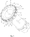
- the face milling tool 10 shown in the drawing comprises a tool head 14 which can be rotated about its central axis 12, on the peripheral surface 16 of which there are a large number of cutting elements 18 and associated chip flutes 20 and in the interior of which a channel system 22 for coolant or Cooling lubricant supply to the cutting elements 18 is formed.
- Coolant grooves 26 introduced on the end face 24 of the tool head 14 and an in 1 front baffle plate 28 shown only approximately in half for coolant deflection into the chip flutes 20 .
- the tool head 14 is held on a shank part 30, at the rear end of which an interface 32 for coupling to a machine spindle is arranged.
- the face milling tool 10 is moved perpendicularly to the central axis 12 and rotated in the direction of the arrow 34, with the cutting elements 18 removing the material with their cutting edge 36 protruding on the front and peripheral sides and the chips being selectively guided through with the aid of the coolant that is deflected to the rear the chip flutes 20 are removed, as will be explained in more detail below.
- each of the cutting elements 18 is assigned its own flute 20, although other configurations, for example with two offset cutting elements per flute, are also conceivable.
- FIG. 2 illustrates the coolant supply via the channel system 22 of the tool head 14.
- the coolant is fed in on the machine side from the interface 32 via an axially running central channel 38 extend outside and open at an outlet opening 42 near an associated flute 20 in the area of the end face 24 of the tool head 14 .
- the outlet openings 42 are each at the bottom of a coolant groove 26, which ends in an orifice 44 in the region of a wall 46 of the flute 20.
- the mouth opening 44 is aligned with the cutting edge 36 of an opposite cutting element 18 .
- the coolant grooves 26 thus run from the outlet opening to the orifice opening 44 deviating from a radial opposite to the Direction of rotation 34 of the tool head 14, with the coolant flow taking place under the baffle plate 28 in a radius to the central axis 12 directly on the end face of the cutting edge 36.
- the baffle plate 28 is expediently formed by a toothed ring that is closed in a circular manner, the radially projecting toothed segments 48 of which cover the longitudinal openings 49 of the coolant grooves 26, while the cutting elements 18 are arranged in the area of the tooth gaps 50 ( 1 ).
- the baffle plate 28 can be formed from a sheet metal blank, in particular by water jet cutting, and can be detachably held on the end face 24 of the tool head 14 by connecting means 52 .
- the cutting elements 18 are in the form of cutting inserts 54 which are each mounted in a peripheral insert seat 58 of the tool head 14 by means of a screw 56 . They delimit a chip removal surface 60 which leads away from the end face 24 to the rear and which, with respect to the central axis 12 - as well as from 1 recognizable - is positively inclined backwards and towards the central axis 12 .
- the chip removal surface 60 has a V-shaped or concavely curved cross-sectional contour in radial cross-section with respect to the central axis, flattening out toward the rear. This forms a chip removal funnel 62 that widens toward the rear, which generates a type of turbine effect at high speeds and also improves tool cooling through the fluid flow generated.
Landscapes
- Engineering & Computer Science (AREA)
- Mechanical Engineering (AREA)
- Auxiliary Devices For Machine Tools (AREA)
- Milling Processes (AREA)
- Drilling And Boring (AREA)
- Cutting Tools, Boring Holders, And Turrets (AREA)
- Milling, Broaching, Filing, Reaming, And Others (AREA)
- Drilling Tools (AREA)
Description
- Die Erfindung betrifft ein Zerspanungswerkzeug, insbesondere Fräs-, Aufbohr- oder Reibwerkzeug, gemäß dem Oberbegriff des Patentanspruchs 1. Ein solches Zerspanungswerkzeug ist aus der
EP 2 298 483 A1 bekannt. - Beim Planfräsen von komplexen Bauteilstrukturen, beispielsweise Motorblöcken, aus Aluminium, ist häufig problematisch, dass die erzeugten Späne gegen das Werkstück geschleudert werden und in Aussparungen des Bauteils verbleiben. Bei herkömmlichen Fräswerkzeugen wird er Kühlmittelstrahl direkt aus dem Werkzeugkopf gegen die Schneide gelenkt. Hat das Werkstück an der zu bearbeitenden Fläche Bohrungen oder eingegossene Kanäle, hat dies zur Folge, dass auch Späne in die Hohlräume gespült werden. Dies zieht einen hohen Reinigungsaufwand nach sich, da die Späne sich nur schlecht und meist nicht prozesssicher entfernen lassen. Die gefertigten Bauteile müssen einem aufwendigen Kontrollprozess auf verbleibende Restspäne unterzogen werden, wobei häufig Ausschuss aufwändig erzeugter Werkstücke in Kauf genommen werden muss.
- Aus der
JP 2914030888 A EP 2 298 483 A1 sind Schraubenköpfe bzw. Prallplatten zur bereichsweisen Abdeckung von Kühlmittelnuten bekannt, wobei aber nur kreisförmige Umfangskonturen offenbart werden. - Ausgehend hiervon liegt der Erfindung die Aufgabe zugrunde, die im Stand der Technik bekannten Zerspanungswerkzeuge zur Vermeidung der vorgenannten Nachteile weiter zu verbessern und eine von dem Werkstück weg gerichtete Spanabfuhr zur Erreichung einer hohen Fertigungsqualität zu unterstützen.
- Zur Lösung dieser Aufgabe wird die Patentanspruch 1 angegebene Merkmalskombination vorgeschlagen. Vorteilhafte Ausgestaltungen und Weiterbildungen der Erfindung ergeben sich aus den abhängigen Ansprüchen.
- Die Erfindung geht von dem Gedanken aus, mit einfachen Maßnahmen an der Werkzeugstirnseite eine Kühlmittelumlenkung zur Spanfreihaltung des Werkstücks zu erzielen. Dementsprechend wird erfindungsgemäß vorgeschlagen, dass die Prallscheibe durch einen Zahnring gebildet ist, dessen radial abstehende Zahnsegmente die Kühlmittelnuten überdecken. Die nach vorne offenen Kühlmittelnuten lassen sich somit einfach in die Stirnfläche des Werkzeugkopfs einarbeiten, während die abdeckende Prallscheibe dafür sorgt, dass der Kühlmittelstrahl nicht einfach frei austritt, sondern unter Aufprägung einer Rückwärtskomponente gezielt gegen die Schneide umgelenkt wird. Dadurch kann das auftreffende Kühlmittel bzw. der Kühlschmierstoff nicht nach vorne ausweichen, sondern wird unter Mitnahme der Späne nach hinten in den Spankanal abgeleitet.
- Eine besonders bevorzugte Ausgestaltung sieht vor, dass die Kühlmittelnuten von der Austrittsöffnung zu der Mündungsöffnung hin entgegen der Rotationsrichtung des Werkzeugkopfs verlaufen. Damit wird verhindert, dass das Kühlmittel und die Späne radial abfliegen, sondern vielmehr gegen den Schneidkörper gedrängt werden.
- Weitere Verbesserungen in dieser Hinsicht ergeben sich dadurch, dass die Kühlmittelnuten abweichend von einer Radialen schräg oder gekrümmt oder tangential verlaufen, und dass die Mündungsöffnung in einer Wand der Spannut ausgebildet ist und zu einer Schneidkante eines Schneidelements hin ausgerichtet ist.
- Vorteilhafterweise begrenzt das Schneidelement eine von der Stirnseite weg nach hinten führende Spanabfuhrfläche, die den Spanfluss vom Werkstück abhält.
- In diesem Zusammenhang ist es günstig, wenn die Spanabfuhrfläche bezüglich der Mittelachse positiv nach hinten geneigt ist, und wenn die Spanabfuhrfläche im Radialquerschnitt bezüglich der Mittelachse eine V-förmige oder konkav gekrümmte, vorzugsweise sich nach hinten abflachende Querschnittskontur aufweist.
- Um die rückwärts gerichtete Spanabfuhr durch eine Sogwirkung bzw. einen Turbineneffekt zu unterstützen, ist es von Vorteil, wenn das Schneidelement und/oder die jeweilige Spannut einen sich nach hinten erweiternden Spanabfuhrtrichter begrenzen.
- Auch herstellungstechnisch ist es von Vorteil, wenn die Prallscheibe aus einem Flachmaterialstück insbesondere durch eine Blechbearbeitungsmethode wie Wasserstrahl- oder Laserschneiden zugeschnitten ist.
- Vorteilhafterweise weist das Kanalsystem eine Mehrzahl von jeweils zu einer Austrittsöffnung verlaufende, in den Werkzeugkopf eingebrachte Zuführbohrungen auf.
- Günstig ist es auch, wenn die Zuführbohrungen von einem axial durch den Werkzeugkopf verlaufenden Zentralkanal abzweigen und von der Mittelachse weg schräg nach außen verlaufen.
- Die erfindungsgemäßen Maßnahmen lassen sich besonders vorteilhaft bei einem Zerspanungswerkzeug realisieren, bei dem die Schneidelemente durch eine in einem jeweiligen umfangsseitigen Plattensitz des Werkzeugkopfs montierte Schneidplatte gebildet sind, wobei an dem Werkzeugkopf zwischen 4 und 50 Schneidelemente in Umfangsrichtung vorzugsweise gleichmäßig verteilt angeordnet sein können.
- Für die Fluidführung ist es auch von Vorteil, wenn die Kühlmittelnuten eine Länge im Bereich von 1 bis 10 mm besitzen.
- Für eine besonders günstige Kühlmittelzufuhr in der Nähe der Schneidelemente ist es vorteilhaft, wenn die Kühlmittelnuten vollständig in einem Randbereich der Stirnseite liegen, wobei sich der Randbereich zwischen dem 0,6- und 1,0-fachen und bevorzugt 0,7- bis 1,0-fachen des Radius der Stirnseite radial erstreckt.
- Im Folgenden wird die Erfindung anhand der in der Zeichnung schematisch dargestellten Ausführungsbeispiele näher erläutert. Es zeigen:
- Fig. 1
- ein Planfräswerkzeug mit einer abgebrochen gezeigten stirnseitigen Prallscheibe zur Kühlmittelumlenkung in perspektivischer Darstellung;
- Fig. 2
- das Werkzeug nach
Fig. 1 in axial geschnittener, abgebrochen perspektivischer Darstellung; - Fig. 3
- eine ausschnittsweise Vergrößerung des Werkzeugs nach
Fig. 1 . - Das in der Zeichnung dargestellte Planfräswerkzeug 10 umfasst einen um seine Mittelachse 12 rotierbaren Werkzeugkopf 14, an dessen Umfangsfläche 16 eine Vielzahl von Schneidelementen 18 und zugeordneten Spannuten 20 und in dessen Innerem ein Kanalsystem 22 zur Kühlmittel- bzw. Kühlschmierstoffzuführung zu den Schneidelementen 18 ausgebildet ist. Dabei sorgen an der Stirnseite 24 des Werkzeugkopfs 14 eingebrachte Kühlmittelnuten 26 und eine die Kühlmittelnuten 26 abdeckende, in
Fig. 1 nur etwa hälftig gezeigte stirnseitige Prallscheibe 28 für eine Kühlmittelumlenkung in die Spannuten 20 hinein. - Der Werkzeugkopf 14 ist an einem Schafteil 30 gehalten, an dessen hinterem Ende eine Schnittstelle 32 zur Kopplung mit einer Maschinenspindel angeordnet ist. Beim Planfräsen eines Werkstücks wird das Planfräswerkzeug 10 senkrecht zur Mittelachse 12 bewegt und in Richtung des Pfeils 34 rotiert, wobei die Schneidelemente 18 mit ihrer stirn- und umfangsseitig überstehenden Schneide 36 den Werkstoff spanend abtragen und die Späne mit Hilfe des nach hinten umgelenkten Kühlmittels gezielt durch die Spannuten 20 abgeführt werden, wie es weiter unten noch näher erläutert wird. Bei dem gezeigten Ausführungsbeispiel ist jedem der Schneidelemente 18 eine eigene Spannut 20 zugeordnet, wobei jedoch auch andere Konfigurationen beispielsweise mit zwei gegeneinander versetzten Schneidelementen pro Spannut denkbar sind.
-
Fig. 2 veranschaulicht die Kühlmittelzuführung über das Kanalsystem 22 des Werkzeugkopfs 14. Die Einspeisung des Kühlmittels erfolgt maschinenseitig von der Schnittstelle 32 her über einen axial verlaufenden Zentralkanal 38. An dessen vorderem Ende zweigen eine Vielzahl von Zuführbohrungen 40 ab, die jeweils von der Mittelachse 12 weg schräg nach außen verlaufen und an einer Austrittsöffnung 42 nahe einer zugeordneten Spannut 20 im Bereich der Stirnseite 24 des Werkzeugkopfs 14 münden. - Wie am besten aus
Fig. 3 zu ersehen, liegen die Austrittsöffnungen 42 jeweils am Boden einer Kühlmittelnut 26, die in einer Mündungsöffnung 44 im Bereich einer Wand 46 der Spannut 20 endet. Dabei ist die Mündungsöffnung 44 zu der Schneide 36 eines gegenüberliegenden Schneidelements 18 hin ausgerichtet. Die Kühlmittelnuten 26 verlaufen somit von der Austrittsöffnung zu der Mündungsöffnung 44 abweichend von einer Radialen entgegen der Rotationsrichtung 34 des Werkzeugkopfs 14, wobei der Kühlmittelfluss unter der Prallscheibe 28 in einem Radius zur Mittelachse 12 direkt stirnseitig auf die Schneide 36 erfolgt. - Zweckmäßig ist die Prallscheibe 28 durch einen kreisförmig geschlossenen Zahnring gebildet, dessen radial abstehende Zahnsegmente 48 die Längsöffnungen 49 der Kühlmittelnuten 26 überdecken, während im Bereich der Zahnlücken 50 die Schneidelemente 18 angeordnet sind (
Fig. 1 ). Dabei kann die Prallscheibe 28 aus einem Blechzuschnitt insbesondere durch Wasserstrahlschneiden gebildet sein und an der Stirnseite 24 des Werkzeugkopfs 14 durch Verbindungsmittel 52 lösbar gehalten sein. - Wie aus
Fig. 3 weiter ersichtlich, sind die Schneidelemente 18 als Schneidplatten 54 ausgebildet, die mittels Schraube 56 jeweils in einem umfangsseitigen Plattensitz 58 des Werkzeugkopfs 14 montiert sind. Sie begrenzen dabei eine von der Stirnseite 24 weg nach hinten führende Spanabfuhrfläche 60, die bezüglich der Mittelachse 12 - wie auch ausFig. 1 erkennbar - positiv nach hinten und zur Mittelachse 12 hin geneigt ist. - Um die Spanabfuhr von dem Werkstück weg nach hinten zu optimieren, besitzt die Spanabfuhrfläche 60 im Radialquerschnitt bezüglich der Mittelachse eine V-förmige bzw. konkav gekrümmte, sich nach hinten abflachende Querschnittskontur. Dadurch wird ein sich nach hinten erweiternder Spanabfuhrtrichter 62 gebildet, der bei hohen Drehzahlen eine Art von Turbineneffekt erzeugt und durch den erzeugten Fluidstrom auch die Werkzeugkühlung verbessert.
Claims (15)
- Zerspanungswerkzeug, insbesondere Fräs-, Aufbohr- oder Reibwerkzeug, mit einem um seine Mittelachse (12) rotierbaren, eine vordere Stirnseite (24) und eine Umfangsfläche (16) aufweisenden Werkzeugkopf (14), mehreren an der Umfangsfläche (16) im Umfangsrichtung verteilt angeordneten Schneidelementen (18) und zugeordneten Spannuten (20), und einem durch den Werkzeugkopf (14) hindurch verlaufenden Kanalsystem (22) zur Kühlmittelzuführung zu den Schneidelementen (18), wobei die Stirnseite (24) des Werkzeugkopfs (14) mit Kühlmittelnuten (26) versehen ist, die jeweils von einer Austrittsöffnung (42) des Kanalsystems (22) zu einer Mündungsöffnung (44) in einer Spannut (20) führen, und wobei Längsöffnungen (49) der Kühlmittelnuten (26) durch eine stirnseitig an dem Werkzeugkopf (14) fixierte Prallscheibe (28) abdeckt sind, dadurch gekennzeichnet, dass die Prallscheibe (28) durch einen Zahnring gebildet ist, dessen radial abstehende Zahnsegmente (48) die Kühlmittelnuten (26) überdecken.
- Zerspanungswerkzeug nach Anspruch 1, dadurch gekennzeichnet, dass die Kühlmittelnuten (26) von der Austrittsöffnung (42) zu der Mündungsöffnung (44) hin entgegen der Rotationsrichtung (34) des Werkzeugkopfs (14) verlaufen.
- Zerspanungswerkzeug nach Anspruch 1 oder 2, dadurch gekennzeichnet, dass die Kühlmittelnuten (26) abweichend von einer Radialen schräg oder gekrümmt oder tangential verlaufen.
- Zerspanungswerkzeug nach einem der Ansprüche 1 bis 3, dadurch gekennzeichnet, dass die Mündungsöffnung (44) in einer Wand (46) der Spannut (20) ausgebildet ist und zu einer Schneidkante (36) eines Schneidelements (18) hin ausgerichtet ist.
- Zerspanungswerkzeug nach einem der Ansprüche 1 bis 4, dadurch gekennzeichnet, dass das Schneidelement (18) eine von der Stirnseite (24) weg nach hinten führende Spanabfuhrfläche (60) begrenzt.
- Zerspanungswerkzeug nach Anspruch 5, dadurch gekennzeichnet, dass die Spanabfuhrfläche (60) bezüglich der Mittelachse (12) positiv nach hinten geneigt ist.
- Zerspanungswerkzeug nach Anspruch 5 oder 6, dadurch gekennzeichnet, dass die Spanabfuhrfläche (60) im Radialquerschnitt bezüglich der Mittelachse (12) eine V-förmige oder konkav gekrümmte, vorzugsweise sich nach hinten abflachende Querschnittskontur aufweist.
- Zerspanungswerkzeug nach einem der Ansprüche 1 bis 7, dadurch gekennzeichnet, dass das Schneidelement (18) und/oder die jeweilige Spannut einen sich nach hinten erweiternden Spanabfuhrtrichter (62) begrenzen.
- Zerspanungswerkzeug nach einem der Ansprüche 1 bis 8, dadurch gekennzeichnet, dass die Prallscheibe (28) aus einem Flachmaterialstück insbesondere durch eine Blechbearbeitungsmethode zugeschnitten ist.
- Zerspanungswerkzeug nach einem der Ansprüche 1 bis 9, dadurch gekennzeichnet, dass das Kanalsystem (22) eine Mehrzahl von jeweils zu einer Austrittsöffnung (42) verlaufende, in den Werkzeugkopf (14) eingebrachte Zuführbohrungen (40) aufweist.
- Zerspanungswerkzeug nach Anspruch 10, dadurch gekennzeichnet, dass die Zuführbohrungen (40) von einem axial durch den Werkzeugkopf (14) verlaufenden Zentralkanal (38) abzweigen und von der Mittelachse (12) weg schräg nach außen verlaufen.
- Zerspanungswerkzeug nach einem der Ansprüche 1 bis 11, dadurch gekennzeichnet, dass die Schneidelemente (18) durch eine in einem jeweiligen umfangsseitigen Plattensitz (58) des Werkzeugkopfs (14) montierte Schneidplatte (54) gebildet sind.
- Zerspanungswerkzeug nach einem der Ansprüche 1 bis 12, dadurch gekennzeichnet, dass an dem Werkzeugkopf (14) zwischen 4 und 50 Schneidelemente (18) in Umfangsrichtung vorzugsweise gleichmäßig verteilt angeordnet sind.
- Zerspanungswerkzeug nach einem der Ansprüche 1 bis 13, dadurch gekennzeichnet, dass die Kühlmittelnuten (26) eine Länge im Bereich von 1 bis 10 mm besitzen.
- Zerspanungswerkzeug nach einem der Ansprüche 1 bis 14, dadurch gekennzeichnet, dass die Kühlmittelnuten (26) vollständig in einem Randbereich der Stirnseite (24) liegen, wobei sich der Randbereich zwischen dem 0,6- und 1,0-fachen des Radius der Stirnseite radial erstreckt.
Applications Claiming Priority (2)
| Application Number | Priority Date | Filing Date | Title |
|---|---|---|---|
| DE102017109369.9A DE102017109369A1 (de) | 2017-05-02 | 2017-05-02 | Zerspanungswerkzeug mit Kühlmittelumlenkung |
| PCT/EP2018/061225 WO2018202726A1 (de) | 2017-05-02 | 2018-05-02 | Zerspanungswerkzeug mit kühlmittelumlenkung |
Publications (2)
| Publication Number | Publication Date |
|---|---|
| EP3618990A1 EP3618990A1 (de) | 2020-03-11 |
| EP3618990B1 true EP3618990B1 (de) | 2023-02-15 |
Family
ID=62186396
Family Applications (1)
| Application Number | Title | Priority Date | Filing Date |
|---|---|---|---|
| EP18725119.4A Active EP3618990B1 (de) | 2017-05-02 | 2018-05-02 | Zerspanungswerkzeug mit kühlmittelumlenkung |
Country Status (8)
| Country | Link |
|---|---|
| US (1) | US11484955B2 (de) |
| EP (1) | EP3618990B1 (de) |
| JP (1) | JP7057377B2 (de) |
| KR (1) | KR102291712B1 (de) |
| CN (1) | CN110730699B (de) |
| DE (1) | DE102017109369A1 (de) |
| HU (1) | HUE061313T2 (de) |
| WO (1) | WO2018202726A1 (de) |
Families Citing this family (9)
| Publication number | Priority date | Publication date | Assignee | Title |
|---|---|---|---|---|
| CN110153475B (zh) * | 2019-06-20 | 2020-06-30 | 靖江市永固汽配制造有限公司 | 一种可降低工件变形的数控铣削加工工装 |
| US10940551B1 (en) | 2019-08-30 | 2021-03-09 | Kennametal Inc. | Lightweight cutting tool |
| US20210187625A1 (en) * | 2019-12-18 | 2021-06-24 | Decatur Diamond, Llc | Rotary cutting tool |
| US11504784B2 (en) | 2020-12-09 | 2022-11-22 | Kennametal Inc. | Cutting tool with interconnected arms for increased stiffness to weight ratio |
| US11571759B2 (en) * | 2020-12-09 | 2023-02-07 | Kennametal Inc. | Cutting tool with directed fluid flow to facilitate chip evacuation |
| US11883894B2 (en) | 2021-07-13 | 2024-01-30 | Kennametal Inc. | Composite cutting tool |
| US11911835B2 (en) | 2022-03-23 | 2024-02-27 | Kennametal Inc. | Lightweight rotary cutting tool |
| EP4382232A1 (de) * | 2022-12-07 | 2024-06-12 | CERATIZIT Besigheim GmbH | Fräswerkzeug |
| CN118808687B (zh) * | 2024-08-07 | 2025-03-21 | 浙江博谷精密机械科技有限公司 | 一种车削电主轴 |
Family Cites Families (18)
| Publication number | Priority date | Publication date | Assignee | Title |
|---|---|---|---|---|
| SE517817C2 (sv) * | 2000-02-11 | 2002-07-16 | Sandvik Ab | Verktyg för spånavskiljande bearbetning med spårformade kylmedelskanaler i ändytan |
| DE10145006A1 (de) * | 2001-09-12 | 2003-04-03 | Maier Gmbh | Scheibenfräserkühlung |
| JP4349824B2 (ja) | 2003-03-13 | 2009-10-21 | オーエスジー株式会社 | 切削工具用締結ボルト |
| DE202004008642U1 (de) * | 2004-05-27 | 2005-09-29 | Kennametal Inc. | Fräswerkzeug |
| JP4821125B2 (ja) * | 2005-02-08 | 2011-11-24 | 株式会社タンガロイ | 転削工具 |
| JP4542460B2 (ja) | 2005-03-31 | 2010-09-15 | 株式会社神戸製鋼所 | 切削工具およびその切削工具を用いた切削方法 |
| CN2858144Y (zh) * | 2005-10-22 | 2007-01-17 | 燕山大学 | 喷吸钻专用圆弧形喷嘴 |
| TW200924879A (en) * | 2005-11-06 | 2009-06-16 | Iscar Ltd | Rotary cutting tool |
| JP5023655B2 (ja) * | 2006-10-24 | 2012-09-12 | 三菱マテリアル株式会社 | 切削工具 |
| DE102010046044A1 (de) * | 2009-09-22 | 2011-04-21 | Gühring Ohg | Reibahle |
| DE102011050176A1 (de) * | 2011-05-06 | 2012-11-08 | Gühring Ohg | Kühlmittelzufuhr |
| JP2014030888A (ja) * | 2012-08-06 | 2014-02-20 | Mitsubishi Materials Corp | 切削工具 |
| JP6084455B2 (ja) * | 2012-12-14 | 2017-02-22 | 兼房株式会社 | 回転切削工具 |
| AT13711U1 (de) * | 2013-05-23 | 2014-07-15 | Ceratizit Austria Gmbh | Rotierendes Werkzeug |
| US9833846B2 (en) * | 2014-08-05 | 2017-12-05 | Kennametal Inc. | Rotary cutting tool with high-pressure, threaded coolant cap |
| US9623497B2 (en) * | 2014-09-11 | 2017-04-18 | Kennametal Inc. | Rotary cutting tool with high-pressure coolant cap |
| CN105772826A (zh) * | 2014-12-19 | 2016-07-20 | 重庆丰德数控机床有限公司 | 一体式带有内冷辐射流道铣刀片 |
| CN205668088U (zh) * | 2015-11-10 | 2016-11-02 | 浙江长兴巨源机械有限公司 | 一种盘铣刀内冷结构 |
-
2017
- 2017-05-02 DE DE102017109369.9A patent/DE102017109369A1/de not_active Withdrawn
-
2018
- 2018-05-02 KR KR1020197035473A patent/KR102291712B1/ko active Active
- 2018-05-02 EP EP18725119.4A patent/EP3618990B1/de active Active
- 2018-05-02 JP JP2019559305A patent/JP7057377B2/ja active Active
- 2018-05-02 CN CN201880029334.8A patent/CN110730699B/zh active Active
- 2018-05-02 WO PCT/EP2018/061225 patent/WO2018202726A1/de not_active Ceased
- 2018-05-02 HU HUE18725119A patent/HUE061313T2/hu unknown
-
2019
- 2019-10-23 US US16/661,780 patent/US11484955B2/en active Active
Also Published As
| Publication number | Publication date |
|---|---|
| KR102291712B1 (ko) | 2021-08-23 |
| WO2018202726A1 (de) | 2018-11-08 |
| HUE061313T2 (hu) | 2023-06-28 |
| EP3618990A1 (de) | 2020-03-11 |
| CN110730699B (zh) | 2021-10-01 |
| US11484955B2 (en) | 2022-11-01 |
| JP2020518477A (ja) | 2020-06-25 |
| US20200055129A1 (en) | 2020-02-20 |
| KR20200003129A (ko) | 2020-01-08 |
| CN110730699A (zh) | 2020-01-24 |
| JP7057377B2 (ja) | 2022-04-19 |
| DE102017109369A1 (de) | 2018-11-08 |
Similar Documents
| Publication | Publication Date | Title |
|---|---|---|
| WO2018202726A1 (de) | Zerspanungswerkzeug mit kühlmittelumlenkung | |
| EP3532226B1 (de) | Zerspanungswerkzeug | |
| DE102011106416B4 (de) | Bohr-Reib-Werkzeug | |
| EP3490746B1 (de) | Zerspanungswerkzeug | |
| EP2962796B1 (de) | Reib-, fräs- oder bohrwerkzeug | |
| DE102015108407B4 (de) | Schneideinsatz und Schneidevorrichtung mit Schneideinsatz mit verbesserter Kühlmittelabgabe | |
| EP2550126B1 (de) | Hochleistungsreibahle mit kühlmittelkanälen | |
| EP3094437B1 (de) | Werkzeugaufnahme mit einem düsenring | |
| DE102015111361A1 (de) | Schneidwerkzeug mit Sprühhaube | |
| EP3359322B1 (de) | Bohrwerkzeug | |
| EP3645201B1 (de) | Schneidwerkzeug und schneidkopf | |
| WO2011000355A1 (de) | Tieflochbohrer | |
| WO2017174542A1 (de) | Spanabhebendes werkzeug zum entgraten von bohrungen | |
| DE102015112631A1 (de) | Rotierendes Schneidwerkzeug mit hochdruckfester Kühlmittelkappe mit Gewinde | |
| EP2313227B1 (de) | Reibahle | |
| DE29923867U1 (de) | Bearbeitungsaggregat | |
| WO2017162688A1 (de) | Spanabhebendes werkzeug | |
| DE102014116856A1 (de) | Kombinationswerkzeug zur Bearbeitung von Zylinderbohrungen | |
| DE102007012874B4 (de) | Spannfutter für eine Werkzeugmaschine sowie eine ein Spannfutter aufweisende Werkzeugmaschine | |
| EP3103575B1 (de) | Bearbeitungswerkzeug für die zerspanende bearbeitung von werkstoffen | |
| DE102016116466B4 (de) | Spanleitdeckel für Schneidwerkzeug | |
| DE102012020185B3 (de) | Reibahle | |
| DE102014102935A1 (de) | Querlochsenker | |
| EP3791980A1 (de) | Spanneinrichtung mit kühlmittelzufuhr | |
| DE202007016019U1 (de) | Werkzeug zur spanabhebenden Feinbearbeitung von Werkstücken |
Legal Events
| Date | Code | Title | Description |
|---|---|---|---|
| STAA | Information on the status of an ep patent application or granted ep patent |
Free format text: STATUS: UNKNOWN |
|
| STAA | Information on the status of an ep patent application or granted ep patent |
Free format text: STATUS: THE INTERNATIONAL PUBLICATION HAS BEEN MADE |
|
| PUAI | Public reference made under article 153(3) epc to a published international application that has entered the european phase |
Free format text: ORIGINAL CODE: 0009012 |
|
| STAA | Information on the status of an ep patent application or granted ep patent |
Free format text: STATUS: REQUEST FOR EXAMINATION WAS MADE |
|
| 17P | Request for examination filed |
Effective date: 20191029 |
|
| AK | Designated contracting states |
Kind code of ref document: A1 Designated state(s): AL AT BE BG CH CY CZ DE DK EE ES FI FR GB GR HR HU IE IS IT LI LT LU LV MC MK MT NL NO PL PT RO RS SE SI SK SM TR |
|
| AX | Request for extension of the european patent |
Extension state: BA ME |
|
| RIN1 | Information on inventor provided before grant (corrected) |
Inventor name: VOGEL, VIKTOR Inventor name: TRINKNER, THOMAS Inventor name: SCHWARZ, SIGURD Inventor name: LEUZE, PETER |
|
| DAV | Request for validation of the european patent (deleted) | ||
| DAX | Request for extension of the european patent (deleted) | ||
| GRAP | Despatch of communication of intention to grant a patent |
Free format text: ORIGINAL CODE: EPIDOSNIGR1 |
|
| STAA | Information on the status of an ep patent application or granted ep patent |
Free format text: STATUS: GRANT OF PATENT IS INTENDED |
|
| INTG | Intention to grant announced |
Effective date: 20220824 |
|
| GRAS | Grant fee paid |
Free format text: ORIGINAL CODE: EPIDOSNIGR3 |
|
| GRAA | (expected) grant |
Free format text: ORIGINAL CODE: 0009210 |
|
| STAA | Information on the status of an ep patent application or granted ep patent |
Free format text: STATUS: THE PATENT HAS BEEN GRANTED |
|
| AK | Designated contracting states |
Kind code of ref document: B1 Designated state(s): AL AT BE BG CH CY CZ DE DK EE ES FI FR GB GR HR HU IE IS IT LI LT LU LV MC MK MT NL NO PL PT RO RS SE SI SK SM TR |
|
| REG | Reference to a national code |
Ref country code: CH Ref legal event code: EP Ref country code: GB Ref legal event code: FG4D Free format text: NOT ENGLISH |
|
| REG | Reference to a national code |
Ref country code: DE Ref legal event code: R096 Ref document number: 502018011591 Country of ref document: DE |
|
| REG | Reference to a national code |
Ref country code: AT Ref legal event code: REF Ref document number: 1547983 Country of ref document: AT Kind code of ref document: T Effective date: 20230315 Ref country code: IE Ref legal event code: FG4D Free format text: LANGUAGE OF EP DOCUMENT: GERMAN |
|
| REG | Reference to a national code |
Ref country code: LT Ref legal event code: MG9D |
|
| REG | Reference to a national code |
Ref country code: NL Ref legal event code: MP Effective date: 20230215 |
|
| REG | Reference to a national code |
Ref country code: HU Ref legal event code: AG4A Ref document number: E061313 Country of ref document: HU |
|
| PG25 | Lapsed in a contracting state [announced via postgrant information from national office to epo] |
Ref country code: RS Free format text: LAPSE BECAUSE OF FAILURE TO SUBMIT A TRANSLATION OF THE DESCRIPTION OR TO PAY THE FEE WITHIN THE PRESCRIBED TIME-LIMIT Effective date: 20230215 Ref country code: PT Free format text: LAPSE BECAUSE OF FAILURE TO SUBMIT A TRANSLATION OF THE DESCRIPTION OR TO PAY THE FEE WITHIN THE PRESCRIBED TIME-LIMIT Effective date: 20230615 Ref country code: NO Free format text: LAPSE BECAUSE OF FAILURE TO SUBMIT A TRANSLATION OF THE DESCRIPTION OR TO PAY THE FEE WITHIN THE PRESCRIBED TIME-LIMIT Effective date: 20230515 Ref country code: NL Free format text: LAPSE BECAUSE OF FAILURE TO SUBMIT A TRANSLATION OF THE DESCRIPTION OR TO PAY THE FEE WITHIN THE PRESCRIBED TIME-LIMIT Effective date: 20230215 Ref country code: LV Free format text: LAPSE BECAUSE OF FAILURE TO SUBMIT A TRANSLATION OF THE DESCRIPTION OR TO PAY THE FEE WITHIN THE PRESCRIBED TIME-LIMIT Effective date: 20230215 Ref country code: LT Free format text: LAPSE BECAUSE OF FAILURE TO SUBMIT A TRANSLATION OF THE DESCRIPTION OR TO PAY THE FEE WITHIN THE PRESCRIBED TIME-LIMIT Effective date: 20230215 Ref country code: HR Free format text: LAPSE BECAUSE OF FAILURE TO SUBMIT A TRANSLATION OF THE DESCRIPTION OR TO PAY THE FEE WITHIN THE PRESCRIBED TIME-LIMIT Effective date: 20230215 Ref country code: ES Free format text: LAPSE BECAUSE OF FAILURE TO SUBMIT A TRANSLATION OF THE DESCRIPTION OR TO PAY THE FEE WITHIN THE PRESCRIBED TIME-LIMIT Effective date: 20230215 |
|
| PG25 | Lapsed in a contracting state [announced via postgrant information from national office to epo] |
Ref country code: SE Free format text: LAPSE BECAUSE OF FAILURE TO SUBMIT A TRANSLATION OF THE DESCRIPTION OR TO PAY THE FEE WITHIN THE PRESCRIBED TIME-LIMIT Effective date: 20230215 Ref country code: PL Free format text: LAPSE BECAUSE OF FAILURE TO SUBMIT A TRANSLATION OF THE DESCRIPTION OR TO PAY THE FEE WITHIN THE PRESCRIBED TIME-LIMIT Effective date: 20230215 Ref country code: IS Free format text: LAPSE BECAUSE OF FAILURE TO SUBMIT A TRANSLATION OF THE DESCRIPTION OR TO PAY THE FEE WITHIN THE PRESCRIBED TIME-LIMIT Effective date: 20230615 Ref country code: GR Free format text: LAPSE BECAUSE OF FAILURE TO SUBMIT A TRANSLATION OF THE DESCRIPTION OR TO PAY THE FEE WITHIN THE PRESCRIBED TIME-LIMIT Effective date: 20230516 Ref country code: FI Free format text: LAPSE BECAUSE OF FAILURE TO SUBMIT A TRANSLATION OF THE DESCRIPTION OR TO PAY THE FEE WITHIN THE PRESCRIBED TIME-LIMIT Effective date: 20230215 |
|
| PG25 | Lapsed in a contracting state [announced via postgrant information from national office to epo] |
Ref country code: SM Free format text: LAPSE BECAUSE OF FAILURE TO SUBMIT A TRANSLATION OF THE DESCRIPTION OR TO PAY THE FEE WITHIN THE PRESCRIBED TIME-LIMIT Effective date: 20230215 Ref country code: RO Free format text: LAPSE BECAUSE OF FAILURE TO SUBMIT A TRANSLATION OF THE DESCRIPTION OR TO PAY THE FEE WITHIN THE PRESCRIBED TIME-LIMIT Effective date: 20230215 Ref country code: EE Free format text: LAPSE BECAUSE OF FAILURE TO SUBMIT A TRANSLATION OF THE DESCRIPTION OR TO PAY THE FEE WITHIN THE PRESCRIBED TIME-LIMIT Effective date: 20230215 Ref country code: DK Free format text: LAPSE BECAUSE OF FAILURE TO SUBMIT A TRANSLATION OF THE DESCRIPTION OR TO PAY THE FEE WITHIN THE PRESCRIBED TIME-LIMIT Effective date: 20230215 Ref country code: CZ Free format text: LAPSE BECAUSE OF FAILURE TO SUBMIT A TRANSLATION OF THE DESCRIPTION OR TO PAY THE FEE WITHIN THE PRESCRIBED TIME-LIMIT Effective date: 20230215 |
|
| PGFP | Annual fee paid to national office [announced via postgrant information from national office to epo] |
Ref country code: IE Payment date: 20230811 Year of fee payment: 6 |
|
| REG | Reference to a national code |
Ref country code: DE Ref legal event code: R097 Ref document number: 502018011591 Country of ref document: DE |
|
| PG25 | Lapsed in a contracting state [announced via postgrant information from national office to epo] |
Ref country code: SK Free format text: LAPSE BECAUSE OF FAILURE TO SUBMIT A TRANSLATION OF THE DESCRIPTION OR TO PAY THE FEE WITHIN THE PRESCRIBED TIME-LIMIT Effective date: 20230215 |
|
| PLBE | No opposition filed within time limit |
Free format text: ORIGINAL CODE: 0009261 |
|
| STAA | Information on the status of an ep patent application or granted ep patent |
Free format text: STATUS: NO OPPOSITION FILED WITHIN TIME LIMIT |
|
| REG | Reference to a national code |
Ref country code: CH Ref legal event code: PL |
|
| PG25 | Lapsed in a contracting state [announced via postgrant information from national office to epo] |
Ref country code: MC Free format text: LAPSE BECAUSE OF FAILURE TO SUBMIT A TRANSLATION OF THE DESCRIPTION OR TO PAY THE FEE WITHIN THE PRESCRIBED TIME-LIMIT Effective date: 20230215 |
|
| 26N | No opposition filed |
Effective date: 20231116 |
|
| GBPC | Gb: european patent ceased through non-payment of renewal fee |
Effective date: 20230515 |
|
| REG | Reference to a national code |
Ref country code: BE Ref legal event code: MM Effective date: 20230531 |
|
| PG25 | Lapsed in a contracting state [announced via postgrant information from national office to epo] |
Ref country code: SI Free format text: LAPSE BECAUSE OF FAILURE TO SUBMIT A TRANSLATION OF THE DESCRIPTION OR TO PAY THE FEE WITHIN THE PRESCRIBED TIME-LIMIT Effective date: 20230215 Ref country code: MC Free format text: LAPSE BECAUSE OF FAILURE TO SUBMIT A TRANSLATION OF THE DESCRIPTION OR TO PAY THE FEE WITHIN THE PRESCRIBED TIME-LIMIT Effective date: 20230215 Ref country code: LU Free format text: LAPSE BECAUSE OF NON-PAYMENT OF DUE FEES Effective date: 20230502 Ref country code: LI Free format text: LAPSE BECAUSE OF NON-PAYMENT OF DUE FEES Effective date: 20230531 Ref country code: CH Free format text: LAPSE BECAUSE OF NON-PAYMENT OF DUE FEES Effective date: 20230531 |
|
| PG25 | Lapsed in a contracting state [announced via postgrant information from national office to epo] |
Ref country code: GB Free format text: LAPSE BECAUSE OF NON-PAYMENT OF DUE FEES Effective date: 20230515 |
|
| PG25 | Lapsed in a contracting state [announced via postgrant information from national office to epo] |
Ref country code: BE Free format text: LAPSE BECAUSE OF NON-PAYMENT OF DUE FEES Effective date: 20230531 |
|
| REG | Reference to a national code |
Ref country code: AT Ref legal event code: MM01 Ref document number: 1547983 Country of ref document: AT Kind code of ref document: T Effective date: 20230502 |
|
| PG25 | Lapsed in a contracting state [announced via postgrant information from national office to epo] |
Ref country code: AT Free format text: LAPSE BECAUSE OF NON-PAYMENT OF DUE FEES Effective date: 20230502 |
|
| PG25 | Lapsed in a contracting state [announced via postgrant information from national office to epo] |
Ref country code: AT Free format text: LAPSE BECAUSE OF NON-PAYMENT OF DUE FEES Effective date: 20230502 |
|
| PG25 | Lapsed in a contracting state [announced via postgrant information from national office to epo] |
Ref country code: BG Free format text: LAPSE BECAUSE OF FAILURE TO SUBMIT A TRANSLATION OF THE DESCRIPTION OR TO PAY THE FEE WITHIN THE PRESCRIBED TIME-LIMIT Effective date: 20230215 |
|
| PG25 | Lapsed in a contracting state [announced via postgrant information from national office to epo] |
Ref country code: BG Free format text: LAPSE BECAUSE OF FAILURE TO SUBMIT A TRANSLATION OF THE DESCRIPTION OR TO PAY THE FEE WITHIN THE PRESCRIBED TIME-LIMIT Effective date: 20230215 |
|
| PG25 | Lapsed in a contracting state [announced via postgrant information from national office to epo] |
Ref country code: IE Free format text: LAPSE BECAUSE OF NON-PAYMENT OF DUE FEES Effective date: 20240502 |
|
| PGFP | Annual fee paid to national office [announced via postgrant information from national office to epo] |
Ref country code: DE Payment date: 20250521 Year of fee payment: 8 |
|
| PGFP | Annual fee paid to national office [announced via postgrant information from national office to epo] |
Ref country code: HU Payment date: 20250523 Year of fee payment: 8 |
|
| PGFP | Annual fee paid to national office [announced via postgrant information from national office to epo] |
Ref country code: IT Payment date: 20250527 Year of fee payment: 8 |
|
| PGFP | Annual fee paid to national office [announced via postgrant information from national office to epo] |
Ref country code: FR Payment date: 20250528 Year of fee payment: 8 |
|
| PG25 | Lapsed in a contracting state [announced via postgrant information from national office to epo] |
Ref country code: CY Free format text: LAPSE BECAUSE OF FAILURE TO SUBMIT A TRANSLATION OF THE DESCRIPTION OR TO PAY THE FEE WITHIN THE PRESCRIBED TIME-LIMIT; INVALID AB INITIO Effective date: 20180502 |
|
| PG25 | Lapsed in a contracting state [announced via postgrant information from national office to epo] |
Ref country code: TR Free format text: LAPSE BECAUSE OF FAILURE TO SUBMIT A TRANSLATION OF THE DESCRIPTION OR TO PAY THE FEE WITHIN THE PRESCRIBED TIME-LIMIT Effective date: 20230215 |