EP3617826B1 - Monitoring system - Google Patents
Monitoring system Download PDFInfo
- Publication number
- EP3617826B1 EP3617826B1 EP18791450.2A EP18791450A EP3617826B1 EP 3617826 B1 EP3617826 B1 EP 3617826B1 EP 18791450 A EP18791450 A EP 18791450A EP 3617826 B1 EP3617826 B1 EP 3617826B1
- Authority
- EP
- European Patent Office
- Prior art keywords
- real
- time detection
- target equipment
- data
- simulation
- Prior art date
- Legal status (The legal status is an assumption and is not a legal conclusion. Google has not performed a legal analysis and makes no representation as to the accuracy of the status listed.)
- Active
Links
- 238000012544 monitoring process Methods 0.000 title claims description 49
- 238000004088 simulation Methods 0.000 claims description 70
- 238000011897 real-time detection Methods 0.000 claims description 67
- 230000005856 abnormality Effects 0.000 claims description 49
- 238000012806 monitoring device Methods 0.000 claims description 36
- 238000004891 communication Methods 0.000 description 27
- 238000000034 method Methods 0.000 description 21
- 238000009825 accumulation Methods 0.000 description 20
- 230000005540 biological transmission Effects 0.000 description 11
- 230000002159 abnormal effect Effects 0.000 description 10
- 238000004458 analytical method Methods 0.000 description 6
- 238000001514 detection method Methods 0.000 description 4
- 238000009434 installation Methods 0.000 description 4
- 239000004020 conductor Substances 0.000 description 3
- 230000005611 electricity Effects 0.000 description 3
- 238000005259 measurement Methods 0.000 description 3
- 238000012545 processing Methods 0.000 description 3
- 230000015556 catabolic process Effects 0.000 description 2
- 238000010586 diagram Methods 0.000 description 2
- 230000000694 effects Effects 0.000 description 2
- 238000004519 manufacturing process Methods 0.000 description 2
- 238000010248 power generation Methods 0.000 description 2
- 238000006731 degradation reaction Methods 0.000 description 1
- 230000001419 dependent effect Effects 0.000 description 1
- 238000011161 development Methods 0.000 description 1
- 230000018109 developmental process Effects 0.000 description 1
- 239000000126 substance Substances 0.000 description 1
- XLYOFNOQVPJJNP-UHFFFAOYSA-N water Substances O XLYOFNOQVPJJNP-UHFFFAOYSA-N 0.000 description 1
Images

Classifications
-
- G—PHYSICS
- G05—CONTROLLING; REGULATING
- G05B—CONTROL OR REGULATING SYSTEMS IN GENERAL; FUNCTIONAL ELEMENTS OF SUCH SYSTEMS; MONITORING OR TESTING ARRANGEMENTS FOR SUCH SYSTEMS OR ELEMENTS
- G05B23/00—Testing or monitoring of control systems or parts thereof
- G05B23/02—Electric testing or monitoring
- G05B23/0205—Electric testing or monitoring by means of a monitoring system capable of detecting and responding to faults
- G05B23/0218—Electric testing or monitoring by means of a monitoring system capable of detecting and responding to faults characterised by the fault detection method dealing with either existing or incipient faults
- G05B23/0243—Electric testing or monitoring by means of a monitoring system capable of detecting and responding to faults characterised by the fault detection method dealing with either existing or incipient faults model based detection method, e.g. first-principles knowledge model
- G05B23/0254—Electric testing or monitoring by means of a monitoring system capable of detecting and responding to faults characterised by the fault detection method dealing with either existing or incipient faults model based detection method, e.g. first-principles knowledge model based on a quantitative model, e.g. mathematical relationships between inputs and outputs; functions: observer, Kalman filter, residual calculation, Neural Networks
-
- G—PHYSICS
- G01—MEASURING; TESTING
- G01M—TESTING STATIC OR DYNAMIC BALANCE OF MACHINES OR STRUCTURES; TESTING OF STRUCTURES OR APPARATUS, NOT OTHERWISE PROVIDED FOR
- G01M99/00—Subject matter not provided for in other groups of this subclass
- G01M99/005—Testing of complete machines, e.g. washing-machines or mobile phones
-
- G—PHYSICS
- G05—CONTROLLING; REGULATING
- G05B—CONTROL OR REGULATING SYSTEMS IN GENERAL; FUNCTIONAL ELEMENTS OF SUCH SYSTEMS; MONITORING OR TESTING ARRANGEMENTS FOR SUCH SYSTEMS OR ELEMENTS
- G05B23/00—Testing or monitoring of control systems or parts thereof
- G05B23/02—Electric testing or monitoring
- G05B23/0205—Electric testing or monitoring by means of a monitoring system capable of detecting and responding to faults
- G05B23/0218—Electric testing or monitoring by means of a monitoring system capable of detecting and responding to faults characterised by the fault detection method dealing with either existing or incipient faults
- G05B23/0224—Process history based detection method, e.g. whereby history implies the availability of large amounts of data
- G05B23/0227—Qualitative history assessment, whereby the type of data acted upon, e.g. waveforms, images or patterns, is not relevant, e.g. rule based assessment; if-then decisions
Definitions
- the present invention relates to a monitoring system.
- US 2007/043539 A1 discloses an abnormality monitoring system and an abnormality monitoring method.
- a simulation section simulates an operation of a field device in the plant by using a device model.
- a comparing section compares actual output data of the field device with simulation output data that is obtained by simulation by the simulation section.
- a judging section judges occurrence of abnormality of the plant based on a comparison result by the comparing section.
- An error estimating section estimates an error between process data and input data, the process data being indicated as the input data to the field device, and the input data being actually inputted to the field device. In this case, the process data is corrected based on an estimation result by the error estimating section, and the corrected process data is inputted to the device model.
- EP 2 048 562 A1 discloses a method of providing at least one input sensor signal for a control and/or monitoring application regarding an installation.
- the method comprises the steps of: providing at least one real sensor signal based on at least one quantity measured at the installation; providing at least one dynamical model of the installation; estimating states on at least the basis of the at least one sensor signal using the dynamical model; generating at least one virtual sensor signal from the estimated states by calculating at least one local condition at the installation from the estimated states and establishing the at least one virtual sensor signal from the at least one local condition; providing the at least one virtual sensor signal as the at least one input sensor signal for the control and/or monitoring application.
- US 2015/346706 A1 discloses a computerized method for automatic monitoring of control systems.
- the method may comprise receiving electronic measurement values, measured on one or more conductors of computerized control devices, where the conductors may be a system bus conductor and/or an inputoutput line of a programmable logic controller.
- the method may comprise automatically calculating normal data patterns based on an analysis of the electronic measurement values.
- the method may comprise matching between new electronic measurement values measured on the computerized control devices and the normal data patterns to automatically detect abnormal data patterns.
- the method may comprise sending automatically an abnormal operation alert in response to the abnormal data patterns.
- the present invention has been made to solve the above-described problems, and an object of the present invention is to provide a monitoring system capable of monitoring an industrial system to be managed with higher accuracy.
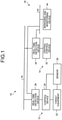
- a monitoring system 18 of the present embodiment may also be applied to transportation equipment such as trains and road traffic, when various infrastructures such as electric power, gas, water supply, chemical, and oil are to be monitored and controlled.
- the plant facility 12 is a plant for manufacturing products, a plant for generating electric power, and the like.
- the plant facility 12 includes target equipment 22, a control device 24, a sensor 26, and a real-time detection device (first real-time detection device) 28.
- the real-time detection device (first real-time detection device) 28 is a part of the monitoring system 18.
- the target equipment 22 is equipment to be monitored and managed by the plant facility 12. In a power generation plant, the target equipment 22 may be a part of the plant facility such as a generator, a gas turbine, and a boiler; or equipment such as a valve, a pump, and a motor of the power generation plant.
- the control device 24 controls the operation of the target equipment 22.
- the control device 24 controls the operation of the target equipment 22, on the basis of information input from the control unit 14, and the detection result of the sensor 26.
- the sensor 26 detects the state of the target equipment 22.
- the sensor 26 detects temperature, pressure, rotation, and the like.
- the real-time detection device (first real-time detection device) 28 is connected between the sensor 26 and the communication bus 16, and between the control device 24 and the communication bus 16.
- the real-time detection device 28 detects information input to and output from the sensor 26 and the control device 24.
- the real-time detection device 28 outputs the detected data to a monitoring device 44 of the monitoring system 18.
- the real-time detection device 28 obtains the state (sensor value) of the target equipment 22 detected by the sensor 26 and the control result of the plant facility 12, as output data of the plant facility 12.
- the control unit 14 monitors the state of the plant facility 12. When an operator or the like inputs an operation, the control unit 14 controls the operation of the plant facility 12.
- the control unit 14 includes a central control device 32 and a real-time detection device (second real-time detection device) 34.
- the central control device 32 is connected to the communication bus 16.
- the central control device 32 includes a display device, an operation console, and the like.
- the central control device 32 causes the display device to display information output from the target equipment 22 and the sensor 26.
- An operator or the like operates the operation console and inputs an operation.
- the central control device 32 transmits the operation to the control device 24 of the plant facility 12 via the communication bus 16.
- the central control device 32 transmits a control command for instructing the target equipment 22 to turn on power supply, and a control command for instructing the target equipment 22 to turn off power supply.
- the real-time detection device (second real-time detection device) 34 is connected between the central control device 32 and the communication bus 16.
- the real-time detection device 34 detects information input to and output from the central control device 32.
- the real-time detection device 34 outputs the detected data to the monitoring device 44 of the monitoring system 18.
- the monitoring system 18 manages and monitors the states of the plant facility 12 and the control unit 14.
- the monitoring system 18 includes the real-time detection devices 28 and 34, a communication bus 42, and the monitoring device (security management device) 44.
- the communication bus 42 connects the real-time detection devices 28 and 34 with the monitoring device 44, and transmits and receives data.
- the monitoring system 18 is disposed in the same facility as that of the plant facility 12 (target equipment 22) and the control unit 14, and is not disposed away from the control unit 14.
- the protocol of data transmitted through the communication bus 42 is different from the protocol of data transmitted through the communication bus 16.
- the real-time detection devices 28 and 34 may also be a single device. In other words, in the present embodiment, a total of two real-time detection devices are used. However, a single real-time detection device may be provided in one of the plant facility 12 and the control unit 14. Moreover, three or more of the real-time detection devices 28 and 34 may be provided.
- the detected data reception unit 50 receives data transmitted from the real-time detection devices 28 and 34.
- the detected data reception unit 50 acquires all the data detected by the real-time detection devices 28 and 34.
- the simulation unit 52 includes an arithmetic unit 60, a central control device model 62, an equipment model 64, and a control device model 66.
- the arithmetic unit 60 performs simulation.
- the central control device model 62 is data that models the central control device 32.
- the equipment model 64 is data that models the target equipment 22 of the plant facility 12.
- the control device model 66 is data that models the control device 24 of the plant facility 12.
- the simulation unit 52 performs simulation on the operation of the industrial plant 10, on the basis of the models of the central control device model 62, the equipment model 64, and the control device model 66.
- the simulation unit 52 acquires information on a control instruction, in other words, a control command that is transmitted from the central control device 32 to the control device 24, from the real-time detection device 34.
- the control command is information on contents of the instruction that is output from the central control device 32 to the control device 24 and that controls the target equipment 22.
- the simulation unit 52 performs simulation of the industrial plant 10, and calculates simulation output data.
- the simulation output data is a calculated value of the output data in simulation, when the industrial plant is operated. In other words, the simulation output data is a calculated value of a parameter corresponding to the actual output data, when the industrial plant 10 is operated.
- the parameter of the output data is a parameter of the sensor value (for example, temperature) detected by the sensor 26, and the control result (for example, an amount of electricity) of the plant facility 12.
- the determination unit 54 compares the data transmitted from the real-time detection devices 28 and 34 with the simulation result of the simulation unit 52. The determination unit 54 then determines whether an abnormality has occurred in the target equipment 22 and the central control device 32, on the basis of the comparison result. Moreover, the determination unit 54 compares the real-time data transmitted from the real-time detection devices 28 and 34 with the previous data stored in the accumulation unit 53. The determination unit 54 then determines whether an abnormality has occurred in the target equipment 22 and the central control device 32, on the basis of the comparison result.
- FIG. 3 is a flowchart illustrating an example of a process performed by the monitoring system.
- the monitoring system 18 detects operations of the target equipment 22 and the sensor 26 by the real-time detection device 28, detects the operation of the central control device 32 by the real-time detection device 34, and transmits the detection result to the monitoring device 44 (step S12).
- the monitoring system 18 simulates the operation state of the industrial plant 10 by the simulation unit 52 in the monitoring device 44 (step S14).
- the simulation unit 52 performs simulation on the basis of the real-time (latest) control command detected by the real-time detection device 34, and calculates the simulation output data.
- the determination unit 54 When it is determined that an abnormality has occurred, the determination unit 54 notifies the occurrence of abnormality, and when it is determined that an abnormality has not occurred, the determination unit 54 notifies that the industrial plant 10 is operated normally. When the industrial plant 10 is operated normally, the notification need not be made.
- the determination unit 54 acquires the current value (latest value) of output data that is output when the industrial plant 10 is operated, from the real-time detection device 28.
- the current value of the output data is the detected value of each parameter such as a sensor value (for example, temperature) detected by the sensor 26, and the control result (for example, an amount of electricity) of the plant facility 12.
- the determination unit 54 acquires simulation output data from the simulation unit 52.
- the determination unit 54 compares the values of the output data with the simulation output data of the same parameter (for example, temperature). If the difference between the values is equal to or more than a predetermined threshold, the determination unit 54 determines that an abnormality has occurred.
- the determination unit 54 determines that abnormality has not occurred. Consequently, when the value of a control command is output to the target equipment 22 as an abnormal value and the value of the output data is output as a false normal-value due to cyber-attacks or the like, the monitoring device 44 can detect the output of this false normal-value.
- the simulation unit 52 calculates an instruction, in other words, a control command output from the central control device 32. In other words, by calculating backward from the actual output data detected by the real-time detection device 28, the simulation unit 52 calculates a control command in simulation that should have been input when the output data is output. By comparing the actual control command detected by the real-time detection device 34 with the control command calculated by the simulation unit 52, the determination unit 54 determines whether an abnormality has occurred in the central control device 32. If the values of the actual control command detected by the real-time detection device 34 and the control command calculated by the simulation unit 52 are equal to or more than a predetermined threshold, the determination unit 54 determines that an abnormality has occurred.
- the determination unit 54 determines that an abnormality has not occurred. Consequently, when the value of the control command is output to the target equipment 22 as an abnormal value and the value of the output data is output as a false normal-value due to cyber-attacks or the like, the monitoring device 44 can detect the output of this false normal-value.
- the determination unit 54 acquires a parameter of the current (latest) control command, in other words, information on what type of control is to be performed on the target equipment 22, from the real-time detection device 34. Then, the determination unit 54 acquires a parameter of a previous control command, in other words, information on what type of control has been performed on the target equipment 22, from the accumulation unit 53. When the parameter of the current (latest) control command is deviated from the parameter of the previous control command, the determination unit 54 determines that an abnormality has occurred. When the parameter of the current (latest) control command is not deviated from the parameter of the previous control command, the determination unit 54 determines that an abnormality has not occurred.
- the determination unit 54 determines that the parameter is deviated. Moreover, when the contents of control carried out by the current control command while the plant facility 12 is in a certain state (for example, when the plant facility 12 is activated, operated, or stopped) are different from the contents of control carried out by the previous control command while the plant facility 12 is in the same state (for example, when the plant facility 12 is activated, operated, or stopped), the determination unit 54 determines that the parameter is deviated. Consequently, when such control that has not been performed previously is about to be performed due to cyber-attacks or the like, the determination unit 54 can determine that the control is abnormal.
- the determination unit 54 determines that the parameter is deviated. Moreover, when the parameter of the output data that is output when control is executed by a certain control command, is different from the parameter of the output data that is output when control is executed by the same control command in the past, the determination unit 54 determines that the parameter is deviated. Thus, when the output data of the parameter that has not been output to the outside is about to be output to the outside by cyber-attacks or the like, the determination unit 54 determines that the output is abnormal.
- the determination unit 54 determines that an abnormality has occurred. In this manner, by detecting a change in the transmission destination by performing comparison with the simulation result or the previous data, it is possible to detect that data is sent to the transmission destination that has not been set, due to cyber-attacks or the like.
- the determination unit 54 determines that an abnormality has occurred. In this manner, by determining the transmission contents, it is possible to detect that a different instruction and different data are transmitted. Consequently, it is possible to determine whether the industrial plant 10 is properly operated.
- the determination unit 54 determines that an abnormality has occurred. In this manner, by determining the transmission order, it is possible to detect that a different instruction and different data are transmitted. Consequently, it is possible to determine whether the industrial plant 10 is properly operated.
- the determination unit 54 determines that an abnormality has occurred. In this manner, by determining the transmission frequency and the amount of transmission data, it is possible to detect that unnecessary data is transmitted, or detect that necessary data is not transmitted. Consequently, it is possible to determine whether the industrial plant 10 is properly operated, and whether a data leakage has occurred.
- the determination unit 54 determines that an abnormality has occurred. By determining the relation in this manner, it is possible to detect a deviation between the instruction and the operation to be executed, and the detected result and the operation result. Consequently, it is possible to determine whether the industrial plant 10 is properly operated.
- the determination unit 54 can detect or predict an abnormality. For example, the determination unit 54 may first calculate the average value of the output data (control result and sensor value) accumulated in the accumulation unit 53. Then, when the current output data is statistically deviated from the average value, the determination unit 54 determines that the target equipment 22 corresponding to the output data is abnormal (broken down).
- the determination unit 54 counts the number of times that the same control is performed. When the number of times that the same control is performed exceeds a threshold, the determination unit 54 predicts that there is a high possibility that an abnormality (breakdown) will occur in the target equipment 22 to be controlled.
- the monitoring device 44 updates the simulation model (central control device model 62, equipment model 64, and control device model 66). For example, the performance of the target equipment 22 may be changed, due to degradation and characteristics of individual pieces of equipment. In such a case, by updating the simulation model, the monitoring device 44 can perform more accurate simulation corresponding to the change in the performance. For example, the monitoring device 44 updates the simulation model from the latest data transmitted from the real-time detection devices 28 and 34, and updates the threshold for determining abnormality. Consequently, it is possible to improve the accuracy of detecting abnormality.
- the monitoring device 44 can calculate the most efficient operational parameter (value of control command) of the target equipment 22, on the basis of the simulation. Furthermore, for example, by updating the simulation model, the monitoring device 44 can change the value of the control command with respect to the target equipment 22 that is suspected to be abnormal, detect the condition that has a high reproducibility of abnormality in simulation, and specify the cause of abnormality. Still furthermore, by updating the simulation model, the monitoring device 44 can more accurately predict the occurrence of abnormality by simulation.
- the simulation unit 52 calculates output data faster than the plant facility 12 performing actual processing.
- the speed from when a control command is input to when the simulation output data is calculated is faster (for example, faster by five times) than the speed from when a control command is input to the target equipment 22 to when the variation result of the output data reflecting the control command is generated. This makes it possible to analyze faster than the real time, and to predict, stop, or warn abnormality such as future overload.
- the monitoring system 18 includes the real-time detection devices 28 and 34, and the monitoring device 44.
- the real-time detection device 28 detects the state (output data) of the target equipment 22.
- the real-time detection device 34 detects the control instruction (control command) output from the central control device 32 that supplies a control instruction to the target equipment 22.
- the monitoring device 44 acquires information (output data and control command) from the real-time detection devices 28 and 34.
- the monitoring device 44 includes the simulation unit 52 (analysis unit) and the determination unit 54.
- the simulation unit 52 simulates the state (output data) of the target equipment 22, with the models of the target equipment 22 and the central control device 32.
- the determination unit 54 compares the results calculated by the analysis unit with the information acquired from the real-time detection devices 28 and 34, and determines whether an abnormality has occurred in the target equipment 22. It is to be noted that the real-time detection devices 28 and 34 may be a single device or three or more devices, instead of being two devices as described above.
- the simulation unit 52 performs simulation on the basis of the information detected by the real-time detection devices 28 and 34.
- the determination unit 54 detects whether an abnormality has occurred in the target equipment 22. For example, an abnormality can occur in the target equipment 22 and the central control device 32 due to cyber-attacks. In such a case also, when an abnormality has occurred in communication information due to cyber-attacks and the target equipment 22 is operated abnormally in reality, in some cases the information detected by the real-time detection devices 28 and 34 cannot indicate abnormality.
- the monitoring system 18 can monitor the industrial system (for example, target equipment 22) to be managed with high accuracy when cyber-attacks occurs, for example.
- the monitoring system 18 is installed in a facility where the target equipment 22 is installed. Thus, even when monitoring a large amount of data, the monitoring system 18 can appropriately monitor the large amount of data without increasing the communication volume with the outside.
- the determination unit 54 updates a predetermined threshold (abnormality determination threshold) for determining abnormality, on the basis of the information (latest data) of the real-time detection devices 28 and 34.
- a predetermined threshold abnormality determination threshold
- the monitoring system 18 can monitor with higher accuracy.
- the analysis unit calculates the instruction, in other words, the control command output from the central control device 32, on the basis of the state (output data) of the target equipment 22.
- the determination unit 54 compares the instruction (control command) calculated by the analysis unit with the instruction (control command) detected and acquired by the real-time detection device 34, and determines whether an abnormality has occurred in the central control device 32.
- the monitoring system 18 calculates the control command by calculating backward from the state of the target equipment 22, and compares the calculated control command with the actual control command. Consequently, the monitoring system 18 can appropriately monitor whether the central control device 32 has an abnormality (outputs an abnormal instruction).
- the monitoring system 18 includes the accumulation unit 53 that accumulates the previous information detected by the real-time detection devices 28 and 34.
- the determination unit 54 determines whether an abnormality has occurred in the target equipment 22, by comparing the previous information accumulated in the accumulation unit 53 with the current information detected by the real-time detection devices 28 and 34. By comparing the current state with the previous state when an abnormality has not occurred, the monitoring system 18 can further improve the monitoring accuracy.
Landscapes
- Physics & Mathematics (AREA)
- General Physics & Mathematics (AREA)
- Engineering & Computer Science (AREA)
- Automation & Control Theory (AREA)
- Artificial Intelligence (AREA)
- Evolutionary Computation (AREA)
- Mathematical Physics (AREA)
- Testing And Monitoring For Control Systems (AREA)
Applications Claiming Priority (2)
| Application Number | Priority Date | Filing Date | Title |
|---|---|---|---|
| JP2017086540A JP6907014B2 (ja) | 2017-04-25 | 2017-04-25 | 管理監視システム |
| PCT/JP2018/011844 WO2018198624A1 (ja) | 2017-04-25 | 2018-03-23 | 管理監視システム |
Publications (3)
| Publication Number | Publication Date |
|---|---|
| EP3617826A1 EP3617826A1 (en) | 2020-03-04 |
| EP3617826A4 EP3617826A4 (en) | 2020-12-16 |
| EP3617826B1 true EP3617826B1 (en) | 2022-03-02 |
Family
ID=63919042
Family Applications (1)
| Application Number | Title | Priority Date | Filing Date |
|---|---|---|---|
| EP18791450.2A Active EP3617826B1 (en) | 2017-04-25 | 2018-03-23 | Monitoring system |
Country Status (5)
| Country | Link |
|---|---|
| US (1) | US11262276B2 (ja) |
| EP (1) | EP3617826B1 (ja) |
| JP (1) | JP6907014B2 (ja) |
| ES (1) | ES2908712T3 (ja) |
| WO (1) | WO2018198624A1 (ja) |
Families Citing this family (8)
| Publication number | Priority date | Publication date | Assignee | Title |
|---|---|---|---|---|
| US11604459B2 (en) * | 2019-07-12 | 2023-03-14 | Emerson Process Management Power & Water Solutions, Inc. | Real-time control using directed predictive simulation within a control system of a process plant |
| JP7232205B2 (ja) * | 2020-01-07 | 2023-03-02 | 株式会社日立製作所 | セキュリティ監視システムおよびセキュリティ監視方法 |
| CN112468346B (zh) * | 2020-12-13 | 2021-07-30 | 北京哈工信息产业股份有限公司 | 一种基于简单网络管理协议的设备监视及预警可视化系统 |
| CN112579398B (zh) * | 2020-12-28 | 2024-07-16 | 中国建设银行股份有限公司 | 监控部署方法及装置 |
| JP7208689B1 (ja) | 2022-06-29 | 2023-01-19 | テレポート株式会社 | 情報処理プログラム |
| DE102022120407A1 (de) | 2022-08-12 | 2024-02-15 | Arburg Gmbh + Co Kg | Verfahren zur Fehlererkennung, Fehlererkennungsvorrichtung und Computerprogrammprodukt |
| US20240118176A1 (en) * | 2022-09-29 | 2024-04-11 | Baker Hughes Holdings Llc | Waveform training of monitoring devices |
| CN117348557B (zh) * | 2023-10-30 | 2024-03-26 | 山东鲁抗机电工程有限公司 | 一种自动化控制系统及控制方法 |
Citations (1)
| Publication number | Priority date | Publication date | Assignee | Title |
|---|---|---|---|---|
| EP2048562B1 (en) * | 2007-10-12 | 2009-08-12 | Siemens Aktiengesellschaft | Method and device for providing at least one input sensor signal for a control and/or monitoring application and control device |
Family Cites Families (7)
| Publication number | Priority date | Publication date | Assignee | Title |
|---|---|---|---|---|
| JPH103313A (ja) * | 1996-06-18 | 1998-01-06 | Unisia Jecs Corp | アクチュエータの制御装置 |
| JP2006323538A (ja) * | 2005-05-17 | 2006-11-30 | Yokogawa Electric Corp | 異常監視システムおよび異常監視方法 |
| US20140114442A1 (en) | 2012-10-22 | 2014-04-24 | The Boeing Company | Real time control system management |
| US20150184549A1 (en) | 2013-12-31 | 2015-07-02 | General Electric Company | Methods and systems for enhancing control of power plant generating units |
| US10108168B2 (en) * | 2014-06-01 | 2018-10-23 | Si-Ga Data Security (2014) Ltd. | Industrial control system smart hardware monitoring |
| EP3026510B1 (en) * | 2014-11-26 | 2022-08-17 | General Electric Company | Methods and systems for enhancing control of power plant generating units |
| JP6176341B2 (ja) * | 2016-01-06 | 2017-08-09 | 横河電機株式会社 | プロセス制御装置及びシステム並びにその健全性判定方法 |
-
2017
- 2017-04-25 JP JP2017086540A patent/JP6907014B2/ja active Active
-
2018
- 2018-03-23 US US16/607,599 patent/US11262276B2/en active Active
- 2018-03-23 EP EP18791450.2A patent/EP3617826B1/en active Active
- 2018-03-23 ES ES18791450T patent/ES2908712T3/es active Active
- 2018-03-23 WO PCT/JP2018/011844 patent/WO2018198624A1/ja unknown
Patent Citations (1)
| Publication number | Priority date | Publication date | Assignee | Title |
|---|---|---|---|---|
| EP2048562B1 (en) * | 2007-10-12 | 2009-08-12 | Siemens Aktiengesellschaft | Method and device for providing at least one input sensor signal for a control and/or monitoring application and control device |
Also Published As
| Publication number | Publication date |
|---|---|
| US11262276B2 (en) | 2022-03-01 |
| ES2908712T3 (es) | 2022-05-03 |
| JP2018185634A (ja) | 2018-11-22 |
| EP3617826A4 (en) | 2020-12-16 |
| US20200072707A1 (en) | 2020-03-05 |
| EP3617826A1 (en) | 2020-03-04 |
| WO2018198624A1 (ja) | 2018-11-01 |
| JP6907014B2 (ja) | 2021-07-21 |
Similar Documents
| Publication | Publication Date | Title |
|---|---|---|
| EP3617826B1 (en) | Monitoring system | |
| CA2545695C (en) | Method and system for predicting remaining life for motors featuring on-line insulation condition monitor | |
| US10503155B2 (en) | Method for controlling a process plant using a redundant local supervisory controller | |
| US11152126B2 (en) | Abnormality diagnosis system and abnormality diagnosis method | |
| US7133727B2 (en) | System and method for continuous online safety and reliability monitoring | |
| JP2002533844A (ja) | 高度な処理能力をもつ電子装置での統計的分析方法 | |
| EP2051086A2 (en) | Method and system for remotely predicting the remaining life of an AC motor system | |
| CN104618079A (zh) | 双线过程控制回路诊断 | |
| EP3627264B1 (en) | Plant assessment system and plant assessment method | |
| JP2021521548A (ja) | 電気機械的マシンの調子を監視して故障を予測するシステム及び方法 | |
| KR20110107575A (ko) | 산업설비 관리시스템 및 이의 운영방법 | |
| CN118365315B (zh) | 基于多源数据分析的配电房故障运维管理方法 | |
| CN106940206A (zh) | 用于故障识别和监视的方法和系统 | |
| JP6841589B2 (ja) | 異常予兆監視システム | |
| KR20110075332A (ko) | 설비 고장 예측 방법 | |
| JP7111173B2 (ja) | 情報処理装置 | |
| CN117742265A (zh) | 一种基于dcs的预警方法及系统 | |
| KR20190130953A (ko) | 스마트 배전반 감시 제어 장치 및 그 방법 | |
| CN112579665A (zh) | 能源设备控制方法、装置及能源设备 | |
| US20200132773A1 (en) | Anoomaly detection system and method for electric drives | |
| US10419313B2 (en) | Industrial network monitoring | |
| CN111146863A (zh) | 一种变电站的电力安全检测方法 | |
| WO2023206522A1 (en) | Method, apparatusand device for hardening assets in ot system and storage medium and computer program product | |
| WO2023206521A1 (en) | Method, apparatus and device for hardening assets in ot system and storage medium and computer program product | |
| US20250028313A1 (en) | Method of providing measure for plant in abnormal state by using artificial intelligence |
Legal Events
| Date | Code | Title | Description |
|---|---|---|---|
| STAA | Information on the status of an ep patent application or granted ep patent |
Free format text: STATUS: THE INTERNATIONAL PUBLICATION HAS BEEN MADE |
|
| PUAI | Public reference made under article 153(3) epc to a published international application that has entered the european phase |
Free format text: ORIGINAL CODE: 0009012 |
|
| STAA | Information on the status of an ep patent application or granted ep patent |
Free format text: STATUS: REQUEST FOR EXAMINATION WAS MADE |
|
| 17P | Request for examination filed |
Effective date: 20191023 |
|
| AK | Designated contracting states |
Kind code of ref document: A1 Designated state(s): AL AT BE BG CH CY CZ DE DK EE ES FI FR GB GR HR HU IE IS IT LI LT LU LV MC MK MT NL NO PL PT RO RS SE SI SK SM TR |
|
| AX | Request for extension of the european patent |
Extension state: BA ME |
|
| DAV | Request for validation of the european patent (deleted) | ||
| DAX | Request for extension of the european patent (deleted) | ||
| A4 | Supplementary search report drawn up and despatched |
Effective date: 20201113 |
|
| RIC1 | Information provided on ipc code assigned before grant |
Ipc: G05B 23/02 20060101AFI20201109BHEP Ipc: F02C 7/00 20060101ALI20201109BHEP Ipc: F01D 25/00 20060101ALI20201109BHEP |
|
| STAA | Information on the status of an ep patent application or granted ep patent |
Free format text: STATUS: EXAMINATION IS IN PROGRESS |
|
| 17Q | First examination report despatched |
Effective date: 20210429 |
|
| GRAP | Despatch of communication of intention to grant a patent |
Free format text: ORIGINAL CODE: EPIDOSNIGR1 |
|
| STAA | Information on the status of an ep patent application or granted ep patent |
Free format text: STATUS: GRANT OF PATENT IS INTENDED |
|
| INTG | Intention to grant announced |
Effective date: 20211007 |
|
| GRAS | Grant fee paid |
Free format text: ORIGINAL CODE: EPIDOSNIGR3 |
|
| GRAA | (expected) grant |
Free format text: ORIGINAL CODE: 0009210 |
|
| STAA | Information on the status of an ep patent application or granted ep patent |
Free format text: STATUS: THE PATENT HAS BEEN GRANTED |
|
| AK | Designated contracting states |
Kind code of ref document: B1 Designated state(s): AL AT BE BG CH CY CZ DE DK EE ES FI FR GB GR HR HU IE IS IT LI LT LU LV MC MK MT NL NO PL PT RO RS SE SI SK SM TR |
|
| REG | Reference to a national code |
Ref country code: GB Ref legal event code: FG4D |
|
| REG | Reference to a national code |
Ref country code: CH Ref legal event code: EP Ref country code: AT Ref legal event code: REF Ref document number: 1472771 Country of ref document: AT Kind code of ref document: T Effective date: 20220315 |
|
| REG | Reference to a national code |
Ref country code: DE Ref legal event code: R096 Ref document number: 602018031712 Country of ref document: DE |
|
| REG | Reference to a national code |
Ref country code: IE Ref legal event code: FG4D |
|
| REG | Reference to a national code |
Ref country code: ES Ref legal event code: FG2A Ref document number: 2908712 Country of ref document: ES Kind code of ref document: T3 Effective date: 20220503 |
|
| REG | Reference to a national code |
Ref country code: NL Ref legal event code: FP |
|
| REG | Reference to a national code |
Ref country code: LT Ref legal event code: MG9D |
|
| PG25 | Lapsed in a contracting state [announced via postgrant information from national office to epo] |
Ref country code: SE Free format text: LAPSE BECAUSE OF FAILURE TO SUBMIT A TRANSLATION OF THE DESCRIPTION OR TO PAY THE FEE WITHIN THE PRESCRIBED TIME-LIMIT Effective date: 20220302 Ref country code: RS Free format text: LAPSE BECAUSE OF FAILURE TO SUBMIT A TRANSLATION OF THE DESCRIPTION OR TO PAY THE FEE WITHIN THE PRESCRIBED TIME-LIMIT Effective date: 20220302 Ref country code: NO Free format text: LAPSE BECAUSE OF FAILURE TO SUBMIT A TRANSLATION OF THE DESCRIPTION OR TO PAY THE FEE WITHIN THE PRESCRIBED TIME-LIMIT Effective date: 20220602 Ref country code: LT Free format text: LAPSE BECAUSE OF FAILURE TO SUBMIT A TRANSLATION OF THE DESCRIPTION OR TO PAY THE FEE WITHIN THE PRESCRIBED TIME-LIMIT Effective date: 20220302 Ref country code: HR Free format text: LAPSE BECAUSE OF FAILURE TO SUBMIT A TRANSLATION OF THE DESCRIPTION OR TO PAY THE FEE WITHIN THE PRESCRIBED TIME-LIMIT Effective date: 20220302 Ref country code: BG Free format text: LAPSE BECAUSE OF FAILURE TO SUBMIT A TRANSLATION OF THE DESCRIPTION OR TO PAY THE FEE WITHIN THE PRESCRIBED TIME-LIMIT Effective date: 20220602 |
|
| REG | Reference to a national code |
Ref country code: AT Ref legal event code: MK05 Ref document number: 1472771 Country of ref document: AT Kind code of ref document: T Effective date: 20220302 |
|
| PG25 | Lapsed in a contracting state [announced via postgrant information from national office to epo] |
Ref country code: PL Free format text: LAPSE BECAUSE OF FAILURE TO SUBMIT A TRANSLATION OF THE DESCRIPTION OR TO PAY THE FEE WITHIN THE PRESCRIBED TIME-LIMIT Effective date: 20220302 Ref country code: LV Free format text: LAPSE BECAUSE OF FAILURE TO SUBMIT A TRANSLATION OF THE DESCRIPTION OR TO PAY THE FEE WITHIN THE PRESCRIBED TIME-LIMIT Effective date: 20220302 Ref country code: GR Free format text: LAPSE BECAUSE OF FAILURE TO SUBMIT A TRANSLATION OF THE DESCRIPTION OR TO PAY THE FEE WITHIN THE PRESCRIBED TIME-LIMIT Effective date: 20220603 Ref country code: FI Free format text: LAPSE BECAUSE OF FAILURE TO SUBMIT A TRANSLATION OF THE DESCRIPTION OR TO PAY THE FEE WITHIN THE PRESCRIBED TIME-LIMIT Effective date: 20220302 |
|
| PG25 | Lapsed in a contracting state [announced via postgrant information from national office to epo] |
Ref country code: SM Free format text: LAPSE BECAUSE OF FAILURE TO SUBMIT A TRANSLATION OF THE DESCRIPTION OR TO PAY THE FEE WITHIN THE PRESCRIBED TIME-LIMIT Effective date: 20220302 Ref country code: SK Free format text: LAPSE BECAUSE OF FAILURE TO SUBMIT A TRANSLATION OF THE DESCRIPTION OR TO PAY THE FEE WITHIN THE PRESCRIBED TIME-LIMIT Effective date: 20220302 Ref country code: RO Free format text: LAPSE BECAUSE OF FAILURE TO SUBMIT A TRANSLATION OF THE DESCRIPTION OR TO PAY THE FEE WITHIN THE PRESCRIBED TIME-LIMIT Effective date: 20220302 Ref country code: PT Free format text: LAPSE BECAUSE OF FAILURE TO SUBMIT A TRANSLATION OF THE DESCRIPTION OR TO PAY THE FEE WITHIN THE PRESCRIBED TIME-LIMIT Effective date: 20220704 Ref country code: EE Free format text: LAPSE BECAUSE OF FAILURE TO SUBMIT A TRANSLATION OF THE DESCRIPTION OR TO PAY THE FEE WITHIN THE PRESCRIBED TIME-LIMIT Effective date: 20220302 Ref country code: CZ Free format text: LAPSE BECAUSE OF FAILURE TO SUBMIT A TRANSLATION OF THE DESCRIPTION OR TO PAY THE FEE WITHIN THE PRESCRIBED TIME-LIMIT Effective date: 20220302 Ref country code: AT Free format text: LAPSE BECAUSE OF FAILURE TO SUBMIT A TRANSLATION OF THE DESCRIPTION OR TO PAY THE FEE WITHIN THE PRESCRIBED TIME-LIMIT Effective date: 20220302 |
|
| REG | Reference to a national code |
Ref country code: CH Ref legal event code: PL |
|
| PG25 | Lapsed in a contracting state [announced via postgrant information from national office to epo] |
Ref country code: IS Free format text: LAPSE BECAUSE OF FAILURE TO SUBMIT A TRANSLATION OF THE DESCRIPTION OR TO PAY THE FEE WITHIN THE PRESCRIBED TIME-LIMIT Effective date: 20220702 Ref country code: AL Free format text: LAPSE BECAUSE OF FAILURE TO SUBMIT A TRANSLATION OF THE DESCRIPTION OR TO PAY THE FEE WITHIN THE PRESCRIBED TIME-LIMIT Effective date: 20220302 |
|
| REG | Reference to a national code |
Ref country code: DE Ref legal event code: R097 Ref document number: 602018031712 Country of ref document: DE |
|
| REG | Reference to a national code |
Ref country code: BE Ref legal event code: MM Effective date: 20220331 |
|
| PLBE | No opposition filed within time limit |
Free format text: ORIGINAL CODE: 0009261 |
|
| STAA | Information on the status of an ep patent application or granted ep patent |
Free format text: STATUS: NO OPPOSITION FILED WITHIN TIME LIMIT |
|
| PG25 | Lapsed in a contracting state [announced via postgrant information from national office to epo] |
Ref country code: MC Free format text: LAPSE BECAUSE OF FAILURE TO SUBMIT A TRANSLATION OF THE DESCRIPTION OR TO PAY THE FEE WITHIN THE PRESCRIBED TIME-LIMIT Effective date: 20220302 Ref country code: LU Free format text: LAPSE BECAUSE OF NON-PAYMENT OF DUE FEES Effective date: 20220323 Ref country code: LI Free format text: LAPSE BECAUSE OF NON-PAYMENT OF DUE FEES Effective date: 20220331 Ref country code: IE Free format text: LAPSE BECAUSE OF NON-PAYMENT OF DUE FEES Effective date: 20220323 Ref country code: DK Free format text: LAPSE BECAUSE OF FAILURE TO SUBMIT A TRANSLATION OF THE DESCRIPTION OR TO PAY THE FEE WITHIN THE PRESCRIBED TIME-LIMIT Effective date: 20220302 Ref country code: CH Free format text: LAPSE BECAUSE OF NON-PAYMENT OF DUE FEES Effective date: 20220331 |
|
| 26N | No opposition filed |
Effective date: 20221205 |
|
| PG25 | Lapsed in a contracting state [announced via postgrant information from national office to epo] |
Ref country code: SI Free format text: LAPSE BECAUSE OF FAILURE TO SUBMIT A TRANSLATION OF THE DESCRIPTION OR TO PAY THE FEE WITHIN THE PRESCRIBED TIME-LIMIT Effective date: 20220302 Ref country code: BE Free format text: LAPSE BECAUSE OF NON-PAYMENT OF DUE FEES Effective date: 20220331 |
|
| P01 | Opt-out of the competence of the unified patent court (upc) registered |
Effective date: 20230522 |
|
| PGFP | Annual fee paid to national office [announced via postgrant information from national office to epo] |
Ref country code: NL Payment date: 20240214 Year of fee payment: 7 |
|
| PG25 | Lapsed in a contracting state [announced via postgrant information from national office to epo] |
Ref country code: MK Free format text: LAPSE BECAUSE OF FAILURE TO SUBMIT A TRANSLATION OF THE DESCRIPTION OR TO PAY THE FEE WITHIN THE PRESCRIBED TIME-LIMIT Effective date: 20220302 Ref country code: CY Free format text: LAPSE BECAUSE OF FAILURE TO SUBMIT A TRANSLATION OF THE DESCRIPTION OR TO PAY THE FEE WITHIN THE PRESCRIBED TIME-LIMIT Effective date: 20220302 |
|
| PGFP | Annual fee paid to national office [announced via postgrant information from national office to epo] |
Ref country code: DE Payment date: 20240130 Year of fee payment: 7 Ref country code: GB Payment date: 20240201 Year of fee payment: 7 |
|
| PG25 | Lapsed in a contracting state [announced via postgrant information from national office to epo] |
Ref country code: HU Free format text: LAPSE BECAUSE OF FAILURE TO SUBMIT A TRANSLATION OF THE DESCRIPTION OR TO PAY THE FEE WITHIN THE PRESCRIBED TIME-LIMIT; INVALID AB INITIO Effective date: 20180323 |
|
| PGFP | Annual fee paid to national office [announced via postgrant information from national office to epo] |
Ref country code: IT Payment date: 20240212 Year of fee payment: 7 Ref country code: FR Payment date: 20240213 Year of fee payment: 7 |
|
| PGFP | Annual fee paid to national office [announced via postgrant information from national office to epo] |
Ref country code: ES Payment date: 20240401 Year of fee payment: 7 |
|
| PG25 | Lapsed in a contracting state [announced via postgrant information from national office to epo] |
Ref country code: MT Free format text: LAPSE BECAUSE OF FAILURE TO SUBMIT A TRANSLATION OF THE DESCRIPTION OR TO PAY THE FEE WITHIN THE PRESCRIBED TIME-LIMIT Effective date: 20220302 |