EP3617684A1 - Sensor device - Google Patents
Sensor device Download PDFInfo
- Publication number
- EP3617684A1 EP3617684A1 EP19194013.9A EP19194013A EP3617684A1 EP 3617684 A1 EP3617684 A1 EP 3617684A1 EP 19194013 A EP19194013 A EP 19194013A EP 3617684 A1 EP3617684 A1 EP 3617684A1
- Authority
- EP
- European Patent Office
- Prior art keywords
- magnetism collection
- ring
- sensor
- magnetism
- disposed
- Prior art date
- Legal status (The legal status is an assumption and is not a legal conclusion. Google has not performed a legal analysis and makes no representation as to the accuracy of the status listed.)
- Granted
Links
- 230000005389 magnetism Effects 0.000 claims abstract description 249
- 238000000465 moulding Methods 0.000 claims abstract description 20
- 230000002093 peripheral effect Effects 0.000 claims description 16
- 238000003780 insertion Methods 0.000 claims description 2
- 230000037431 insertion Effects 0.000 claims description 2
- 238000001746 injection moulding Methods 0.000 abstract description 10
- 238000000034 method Methods 0.000 description 10
- 229920005989 resin Polymers 0.000 description 10
- 239000011347 resin Substances 0.000 description 10
- 230000005405 multipole Effects 0.000 description 6
- 238000001514 detection method Methods 0.000 description 5
- 238000002347 injection Methods 0.000 description 4
- 239000007924 injection Substances 0.000 description 4
- 239000007769 metal material Substances 0.000 description 4
- 229920003002 synthetic resin Polymers 0.000 description 3
- 239000000057 synthetic resin Substances 0.000 description 3
- 238000003466 welding Methods 0.000 description 3
- 230000000694 effects Effects 0.000 description 2
- 239000000696 magnetic material Substances 0.000 description 2
- 239000000463 material Substances 0.000 description 2
- 230000000052 comparative effect Effects 0.000 description 1
- 230000008878 coupling Effects 0.000 description 1
- 238000010168 coupling process Methods 0.000 description 1
- 238000005859 coupling reaction Methods 0.000 description 1
- 238000006073 displacement reaction Methods 0.000 description 1
- 238000010438 heat treatment Methods 0.000 description 1
- 230000007935 neutral effect Effects 0.000 description 1
- 239000011800 void material Substances 0.000 description 1
Images


Classifications
-
- G—PHYSICS
- G01—MEASURING; TESTING
- G01L—MEASURING FORCE, STRESS, TORQUE, WORK, MECHANICAL POWER, MECHANICAL EFFICIENCY, OR FLUID PRESSURE
- G01L3/00—Measuring torque, work, mechanical power, or mechanical efficiency, in general
- G01L3/02—Rotary-transmission dynamometers
- G01L3/04—Rotary-transmission dynamometers wherein the torque-transmitting element comprises a torsionally-flexible shaft
- G01L3/10—Rotary-transmission dynamometers wherein the torque-transmitting element comprises a torsionally-flexible shaft involving electric or magnetic means for indicating
- G01L3/101—Rotary-transmission dynamometers wherein the torque-transmitting element comprises a torsionally-flexible shaft involving electric or magnetic means for indicating involving magnetic or electromagnetic means
- G01L3/104—Rotary-transmission dynamometers wherein the torque-transmitting element comprises a torsionally-flexible shaft involving electric or magnetic means for indicating involving magnetic or electromagnetic means involving permanent magnets
-
- G—PHYSICS
- G01—MEASURING; TESTING
- G01L—MEASURING FORCE, STRESS, TORQUE, WORK, MECHANICAL POWER, MECHANICAL EFFICIENCY, OR FLUID PRESSURE
- G01L5/00—Apparatus for, or methods of, measuring force, work, mechanical power, or torque, specially adapted for specific purposes
- G01L5/22—Apparatus for, or methods of, measuring force, work, mechanical power, or torque, specially adapted for specific purposes for measuring the force applied to control members, e.g. control members of vehicles, triggers
- G01L5/221—Apparatus for, or methods of, measuring force, work, mechanical power, or torque, specially adapted for specific purposes for measuring the force applied to control members, e.g. control members of vehicles, triggers to steering wheels, e.g. for power assisted steering
Definitions
- the present invention relates to a sensor device.
- JP 2018-84444 A There is known a torque sensor that detects torque applied to a steering shaft as described in Japanese Patent Application Publication No. 2018-84444 ( JP 2018-84444 A ).
- the steering shaft has an input shaft and an output shaft.
- the input shaft and the output shaft are connected to each other by a torsion bar.
- the torque sensor has a permanent magnet fixed to the input shaft, a pair of magnetic yokes fixed to the output shaft and disposed in a magnetic field formed by the permanent magnet, a pair of magnetism collection rings that guide magnetism from the magnetic yokes, a holder that holds the magnetism collection rings, and a sensor element that generates a detection signal on the basis of the magnetism that is guided by the magnetism collection rings.
- the magnetism collection rings according to JP 2018-84444 A have a first magnetism collection ring and a second magnetism collection ring. The first magnetism collection ring and the second magnetism collection ring are disposed side by side in an axial direction of the output shaft.
- the first magnetism collection ring has a first ring portion that surrounds the magnetic yokes, and a first magnetism collection portion that extends toward the radially outer side from the first ring portion.
- the second magnetism collection ring has a second ring portion that surrounds the magnetic yokes, and a second magnetism collection portion that extends toward the radially outer side from the second ring portion.
- the sensor element is disposed between the first magnetism collection portion and the second magnetism collection portion. The sensor element detects magnetism that passes between the first magnetism collection portion and the second magnetism collection portion.
- the holder has a first holder formed by insert molding so as to surround the first magnetism collection ring, and a second holder formed by insert molding so as to surround the second magnetism collection ring.
- the first holder and the second holder are covered by a housing formed by injection molding.
- the first holder and the second holder are occasionally deformed so as to be collapsed by a molding pressure applied to form the housing by injection molding.
- a force due to the deformation of the first holder may act on the first magnetism collection portion of the first magnetism collection ring, which may vary the positional relationship of the first magnetism collection portion with respect to the sensor element.
- a force due to the deformation of the second holder may act on the second magnetism collection portion, which may vary the positional relationship of the second magnetism collection portion with respect to the sensor element. Such fluctuations in positional relationship may affect the detection precision of the sensor element in detecting magnetism that passes between the first magnetism collection portion and the second magnetism collection portion.
- An aspect of the present invention provides a sensor device including: a permanent magnet attached to a first shaft and magnetized in a circumferential direction; a magnetic yoke that is fixed to a second shaft coupled to the first shaft and is disposed in a magnetic field formed by the permanent magnet; a first magnetism collection ring that has an annular first ring portion that surrounds the magnetic yoke and a first magnetism collection portion that includes a portion disposed on a radially outer side of the first ring portion; a second magnetism collection ring disposed side by side with the first magnetism collection ring in an axial direction of the second shaft, the second magnetism collection ring having an annular second ring portion that surrounds the magnetic yoke and a second magnetism collection portion that includes a portion disposed on a radially outer side of the second ring portion; a housing formed by insert molding so as to integrally surround the first ring portion and the second ring portion; and a sensor element that detects magnetism of
- the housing has a ring portion cover portion that integrally surrounds and holds the first ring portion and the second ring portion, and a sensor cover portion that surrounds and holds the first magnetism collection portion, the second magnetism collection portion, and the sensor element; and the sensor cover portion houses the sensor element as interposed between the first magnetism collection portion and the second magnetism collection portion, and has an opening portion for insertion of the sensor element into the sensor cover portion covered by a lid portion.
- the sensor cover portion that is configured to house the sensor element as interposed between the first magnetism collection portion and the second magnetism collection portion is molded.
- the sensor element is housed inside the sensor cover portion via the opening portion, and the opening portion is closed by the lid portion.
- the sensor element is not housed inside a die for forming the housing by insert molding when the housing is formed by insert molding.
- a molding pressure applied to mold the housing does not act to fluctuate the positional relationship of the sensor element with the first magnetism collection portion and with the second magnetism collection portion.
- the opening portion of the sensor cover portion may open in the axial direction of the first shaft and the second shaft; the first magnetism collection portion and the second magnetism collection portion may face each other in the axial direction inside the sensor cover portion; the sensor element may be mounted on a circuit portion formed with a first through hole that penetrates in the axial direction; a projection portion may be provided inside the sensor cover portion and project in the axial direction from a bottom wall portion on which the circuit portion is disposed; and the projection portion may be inserted through the first through hole of the circuit portion.
- the circuit portion is assembled inside the sensor cover portion by housing the circuit portion, on which the sensor element is mounted, inside the sensor cover portion via the opening portion and inserting the projection portion through the first through hole of the circuit portion.
- the projection portion is provided on the bottom wall portion of the sensor housing portion. Therefore, the position of assembly of the sensor element to the sensor cover portion can be determined by inserting the projection portion through the first through hole of the circuit portion.
- the first magnetism collection portion may be positioned on a side on which the opening portion opens with respect to the second magnetism collection portion; the first magnetism collection portion may be formed separately from the first ring portion, and disposed between end portions of the first ring portion, which has a C-shape, in the circumferential direction; the first magnetism collection portion may be formed with a second through hole that penetrates in the axial direction; and the projection portion may be inserted through the second through hole.
- the first magnetism collection portion may be positioned on a side on which the opening portion opens with respect to the second magnetism collection portion; the first magnetism collection portion may be formed separately from the first ring portion, and disposed on the radially outer side of the first ring portion; the first magnetism collection portion may be formed with a second through hole that penetrates in the axial direction; and the projection portion may be inserted through the second through hole.
- the first magnetism collection portion is formed separately from the first ring portion.
- the circuit portion can be assembled with the first magnetism collection portion removed when the circuit portion, on which the sensor element is mounted, is housed inside the sensor cover portion via the opening portion.
- the circuit portion can be easily installed in the sensor cover portion. Both the position of assembly of the first magnetism collection portion to the first ring portion and the position of assembly of the first magnetism collection portion to the sensor element can be determined by inserting the projection portion through the second through hole that is provided in the first magnetism collection portion.
- a torque sensor 1 as the sensor device includes a torsion bar 13, a cylindrical permanent magnet 20, a cylindrical magnetic yoke 30, a cylindrical magnetism collection ring 40 disposed so as to surround the magnetic yoke 30, a housing 50 that holds the magnetism collection ring 40, and a sensor unit 110.
- the torque sensor 1 detects torque applied to a rotary shaft 10 such as a steering shaft of an electric power steering system, for example.
- the rotary shaft 10 is composed of an input shaft 11, an output shaft 12, and the torsion bar 13.
- the torsion bar 13 that serves as a coupling shaft is disposed between the input shaft 11 servings as a first shaft and the output shaft 12 serving as a second shaft.
- the input shaft 11 and the output shaft 12 are coupled to each other on the same axis via the torsion bar 13.
- the permanent magnet 20 is coupled to the input shaft 11.
- the permanent magnet 20 has a cylindrical holding portion 21 and a multipole magnet 22.
- the holding portion 21 is externally fitted with an end portion of the input shaft 11 on the output shaft 12 side.
- the holding portion 21 is attached so as to be rotatable together with the input shaft 11.
- the multipole magnet 22 is attached to the outer peripheral surface of the holding portion 21.
- the multipole magnet 22 is structured such that N and S magnetic poles are disposed alternately in the circumferential direction of the holding portion 21.
- the magnetic yoke 30 is coupled to the output shaft 12.
- the magnetic yoke 30 has an annular first magnetic yoke 31 and an annular second magnetic yoke 32.
- the first magnetic yoke 31 and the second magnetic yoke 32 are disposed coaxially with the output shaft 12, and fixed so as to be rotatable together with the output shaft 12.
- the first magnetic yoke 31 and the second magnetic yoke 32 are disposed around the multipole magnet 22 via a predetermined clearance therefrom.
- the first magnetic yoke 31 and the second magnetic yoke 32 are disposed in a magnetic field formed by the multipole magnet 22.
- the first magnetic yoke 31 and the second magnetic yoke 32 are disposed so as to face each other with a predetermined clearance therebetween in an axial direction X.
- the axial direction X is the axial direction of the output shaft 12, and is parallel to the axis of the input shaft 11 and the output shaft 12.
- the first magnetic yoke 31 has a first annular portion 31a and a plurality of first lug portions 31b that extend toward the second magnetic yoke 32 from the inner peripheral surface of the first annular portion 31a.
- the first lug portions 31b are disposed at equal intervals in the circumferential direction on the inner peripheral surface of the first annular portion 31a.
- the second magnetic yoke 32 has a second annular portion 32a and a plurality of second lug portions 32b that extend toward the first magnetic yoke 31 from the inner peripheral surface of the second annular portion 32a.
- the second lug portions 32b are disposed at equal intervals in the circumferential direction on the inner peripheral surface of the second annular portion 32a.
- the first magnetic yoke 31 and the second magnetic yoke 32 are molded in a synthetic resin body 33 with the first lug portions 31b and the second lug portions 32b displaced from each other by a constant distance in the circumferential direction.
- the inner peripheral surfaces of the first magnetic yoke 31 and the second magnetic yoke 32 are exposed from the synthetic resin body 33 to a space in the inner peripheral region.
- the outer peripheral surfaces of the first annular portion 31a and the second annular portion 32a are exposed from the synthetic resin body 33 to a space in the outer peripheral region.
- the first magnetic yoke 31 and the second magnetic yoke 32 are constituted of a magnetic material.
- the magnetism collection ring 40 has an annular first magnetism collection ring 41 that guides and collects magnetism of the first magnetic yoke 31, and an annular second magnetism collection ring 42 that guides and collects magnetism of the second magnetic yoke 32.
- the first magnetism collection ring 41 and the second magnetism collection ring 42 are disposed side by side with a predetermined clearance therebetween in the axial direction X.
- the first magnetism collection ring 41 and the second magnetism collection ring 42 are constituted of a magnetic material.
- the housing 50 has a ring portion cover portion 60 that surrounds and holds a first ring portion 41a of the first magnetism collection ring 41 and a second ring portion 42a of the second magnetism collection ring 42, and a sensor cover portion 70 that houses a first magnetism collection portion 41b of the first magnetism collection ring 41, a second magnetism collection portion 42b of the second magnetism collection ring 42, and the sensor unit 110.
- the first ring portion 41a and the second ring portion 42a are disposed side by side in the axial direction X.
- the ring portion cover portion 60 and the sensor cover portion 70 are formed integrally from the same resin material.
- the sensor cover portion 70 extends toward the radially outer side from the ring portion cover portion 60.
- the sensor cover portion 70 has a generally rectangular shape when seen in the axial direction X.
- the sensor cover portion 70 has a sensor housing portion 71 that houses the sensor unit 110 as interposed between the first magnetism collection portion 41b and the second magnetism collection portion 42b, an opening portion 72 that opens in the axial direction X, and a lid portion 73 that closes the opening portion 72.
- the sensor cover portion 70 extends toward the radially outer side from the ring portion cover portion 60.
- the second magnetism collection ring 42 has the second ring portion 42a that is disposed at the outer periphery of the second magnetic yoke 32 with a clearance therefrom so as to surround the second magnetic yoke 32, and the second magnetism collection portion 42b that includes a portion disposed on the radially outer side of the second ring portion 42a.
- the second ring portion 42a has a second annular portion 42c that has a C-shape, and two second extension portions 42d that extend toward the radially outer side from respective end portions of the second annular portion 42c in the circumferential direction.
- the second ring portion 42a is formed integrally with the second extension portions 42d.
- the second magnetism collection portion 42b is formed separately from the second extension portions 42d.
- the second extension portions 42d are disposed in parallel with each other.
- the second extension portions 42d extend in a direction (hereinafter referred to as an "extension direction Z") in which the sensor cover portion 70 extends.
- the second extension portions 42d face each other in a direction (hereinafter referred to as a "width direction Y") that is orthogonal to the direction in which the sensor cover portion 70 extends.
- the second magnetism collection portion 42b is disposed outside the second annular portion 42c.
- the second magnetism collection portion 42b is covered by the housing 50 with a part of the second magnetism collection portion 42b formed by insert molding, and disposed as interposed between the second extension portions 42d in the width direction Y.
- the second magnetism collection portion 42b has a second flat plate portion 42e and second sensor facing portions 42f that face a sensor element 111 of the sensor unit 110.
- the longitudinal portion of the second flat plate portion 42e has a rectangular shape to extend in the width direction Y when seen in the axial direction X. End portions of the second flat plate portion 42e in the width direction Y are formed to be bent to extend in a direction away from the first magnetism collection ring 41 in the axial direction X. Portions of the second flat plate portion 42e that extend in the axial direction X abut against the second extension portions 42d.
- the second sensor facing portions 42f are formed to extend in a direction closer to the second annular portion 42c in the extension direction Z from a surface of the second flat plate portion 42e on the second annular portion 42c side.
- the second sensor facing portions 42f have a rectangular shape when seen in the axial direction X.
- a pair of the second sensor facing portions 42f are provided.
- the second magnetism collection ring 42 is constituted of a metal material.
- the first magnetism collection ring 41 has the first ring portion 41a that is disposed at the outer periphery of the first magnetic yoke 31 with a clearance therefrom so as to surround the first magnetic yoke 31, and the first magnetism collection portion 41b that includes a portion disposed on the radially outer side of the first ring portion 41a.
- the first ring portion 41a has a first annular portion 41c that has a C-shape, and two first extension portions 41d that extend toward the radially outer side from respective end portions of the first annular portion 41c in the circumferential direction.
- the first ring portion 41a is formed integrally with the first extension portions 41d.
- the first magnetism collection portion 41b is formed separately from the first extension portions 41d.
- the first extension portions 41d are disposed in parallel with each other.
- the first extension portions 41d extend in the extension direction Z from the respective end portions of the first annular portion 41c in the circumferential direction.
- the first extension portions 41d face each other in the width direction Y.
- the first magnetism collection portion 41b is disposed outside the first annular portion 41c.
- the first magnetism collection portion 41b has a first flat plate portion 41e, first sensor facing portions 41f that face the sensor element 111 of the sensor unit 110, and a positioning portion 43.
- the longitudinal portion of the first flat plate portion 41e has a rectangular shape to extend in the width direction Y when seen in the extension direction Z. End portions of the first flat plate portion 41e in the width direction Y are formed to be bent to extend toward the first annular portion 41c in the extension direction Z. Portions of the first flat plate portion 41e that extend in the extension direction Z abut against the first extension portions 41d.
- the positioning portion 43 is disposed on the radially outer side of the first annular portion 41c with respect to the first extension portions 41d in the extension direction Z.
- the first sensor facing portions 41f extend from the first flat plate portion 41e toward the second magnetism collection portion 42b in the axial direction X, and are formed to be bent to extend toward the first annular portion 41c in the extension direction Z.
- the first sensor facing portions 41f have a rectangular shape when seen in the axial direction X.
- a pair of first sensor facing portions 41f are provided.
- the first sensor facing portions 41f and the second sensor facing portions 42f face each other in the axial direction X with the sensor unit 110 disposed therebetween.
- the positioning portion 43 is formed to extend away from the first annular portion 41c in the extension direction Z, and has a small plate portion 43a and a large plate portion 43b arranged in this order from the base end side toward the distal end side.
- the small plate portion 43a is formed to be smaller in the width direction Y than the large plate portion 43b.
- a second through hole 43c is provided in the center portion of the large plate portion 43b to penetrate in the axial direction X.
- the first sensor facing portions 41f are disposed on the second magnetism collection portion 42b side with respect to the positioning portion 43 in the axial direction X.
- the first magnetism collection ring 41 is constituted of a metal material.
- the first sensor facing portions 41f of the first magnetism collection portion 41b and the second sensor facing portions 42f of the second magnetism collection portion 42b are disposed so as to face each other with a predetermined clearance therebetween in the axial direction X.
- the ring portion cover portion 60 has a generally cylindrical shape so as to surround both the first annular portion 41c of the first ring portion 41a and the second annular portion 42c of the second ring portion 42a.
- the ring portion cover portion 60 is formed with a through hole 61 that penetrates in the axial direction X.
- the first annular portion 41c of the first ring portion 41a and the second annular portion 42c of the second ring portion 42a are exposed to a space on the inner peripheral side of the through hole 61 of the ring portion cover portion 60.
- the rotary shaft 10, the permanent magnet 20, and the magnetic yoke 30 are disposed on the inner peripheral side of the through hole 61 of the ring portion cover portion 60.
- the magnetic yoke 30 coupled to the output shaft 12 is disposed on the outer peripheral side of the permanent magnet 20 coupled to the input shaft 11.
- the first annular portion 41c of the first ring portion 41a faces the first magnetic yoke 31
- the second annular portion 42c of the second ring portion 42a faces the second magnetic yoke 32 in the radial direction of the output shaft 12.
- the ring portion cover portion 60 has a flange portion 62 that overhangs outward from the outer peripheral surface thereof over the entire circumference. The overhanging length of the flange portion 62 is constant over the entire circumference.
- the ring portion cover portion 60 has a pair of attachment portions 63 that overhang outward from the outer peripheral surface of the flange portion 62.
- the attachment portions 63 are provided on respective sides of the flange portion 62 in the width direction Y.
- the attachment portions 63 are provided with attachment holes 64 that penetrate in the axial direction X.
- the attachment holes 64 are used for attachment to an object for attachment such as a housing of an electric power steering system. Fixing materials such as screws (not illustrated) are inserted through the attachment holes 64 to attach the ring portion cover portion 60 to the object for attachment.
- the sensor housing portion 71 of the sensor cover portion 70 has a bottom wall 74 on which the sensor unit 110 is placed, and a side wall 75 that separates a space inside the sensor housing portion 71 and the outside from each other. A part of the first extension portions 41d and a part of the second extension portions 42d are exposed to the side wall 75.
- the bottom wall 74 has a first bottom wall portion 74a and a second bottom wall portion 74b arranged in this order from the base end side toward the distal end side in the extension direction Z.
- the second bottom wall portion 74b is formed to be smaller in the width direction Y and smaller in the extension direction Z than the first bottom wall portion 74a.
- the first bottom wall portion 74a is formed integrally with a placement portion 74c that projects in the axial direction X from the first bottom wall portion 74a toward the opening portion 72.
- the placement portion 74c has an elliptical column shape.
- the placement portion 74c has an elliptical cross-sectional shape in a direction that is orthogonal to the axial direction X.
- the placement portion 74c is formed integrally with a projection portion 76 that projects in the axial direction X from the top surface of the placement portion 74c toward the opening portion 72.
- the projection portion 76 has a circular column shape.
- a plurality of signal terminals 77 that extend in the axial direction X are exposed to the second bottom wall portion 74b.
- a connector portion 78 for connection with an external device is provided on a surface of the sensor housing portion 71 on the opposite side from the opening portion 72.
- the signal terminals 77 are electrically connected to the connector portion 78.
- the top surface of the placement portion 74c functions as a bottom wall portion of the sensor housing portion 71 on which a circuit board 112 to be discussed later is to be disposed.
- the lid portion 73 has a first lid portion 73a and a second lid portion 73b arranged in this order from the base end side toward the distal end side in the extension direction Z.
- the second lid portion 73b is formed to be smaller in the width direction Y and smaller in the extension direction Z than the first lid portion 73a.
- the lid portion 73 is fitted with the opening portion 72 to close the opening portion 72.
- the sensor unit 110 will be described. As illustrated in FIGS. 2 and 7 , the sensor unit 110 has the sensor element 111 and the circuit board 112 to which the sensor element 111 is connected.
- the circuit board 112 has a first circuit board portion 112a and a second circuit board portion 112b arranged in this order from the base end side toward the distal end side in the extension direction Z.
- the second circuit board portion 112b is formed to be smaller in the width direction Y and smaller in the extension direction Z than the first circuit board portion 112a.
- a pair of notches 112c are provided at an end portion of the first circuit board portion 112a on the base end side in the extension direction Z.
- the notches 112c have a rectangular shape when the circuit board 112 is seen in the axial direction X.
- the sensor element 111 has a rectangular parallelepiped shape, for example.
- a magnetism detection element such as a Hall element, for example, is adopted as the sensor element 111.
- the sensor element 111 includes two sensor elements, namely a first sensor element 111a and a second sensor element 111b, provided redundantly.
- the first sensor element 111a and the second sensor element 111b are disposed side by side in the width direction Y.
- the first sensor element 111a and the second sensor element 111b are formed to be larger than the notches 112c when seen in the axial direction X.
- the first sensor element 111a and the second sensor element 111b are mounted at positions overlapping the notches 112c when seen in the axial direction X.
- the first sensor element 111a and the second sensor element 111b are mounted on the circuit board 112
- the first sensor element 111a and the second sensor element 111b are mounted on a surface of the circuit board 112 on the second magnetism collection portion 42b side.
- the second circuit board portion 112b is formed with a plurality of terminal holes 114 that penetrate in the axial direction X.
- No electronic components are mounted on a portion of the first circuit board portion 112a on the distal end side in the extension direction Z, that is, a portion of the circuit board 112 between the notches 112c and the terminal holes 114, and this portion is formed with a first through hole 113.
- the first through hole 113 penetrates in the axial direction X.
- the inside diameter of the first through hole 113 is set to be equal to the inside diameter of the second through hole 43c of the positioning portion 43.
- portions of the first extension portions 41d on the first annular portion 41c side in the extension direction Z are embedded in the side wall 75, and portions thereof on the opposite side from the first annular portion 41c in the extension direction Z are exposed in the sensor housing portion 71.
- the second extension portions 42d are covered by the first bottom wall portion 74a except for surfaces of the second extension portions 42d on the opening portion 72 side, and the surfaces of the second extension portions 42d on the opening portion 72 side are exposed in the sensor housing portion 71.
- the second magnetism collection portion 42b is covered by the first bottom wall portion 74a except for a surface of the second magnetism collection portion 42b on the opening portion 72 side, and the surface of the second magnetism collection portion 42b on the opening portion 72 side is exposed in the sensor housing portion 71.
- the projection portion 76 has a shaft portion 76a that extends in the axial direction X, and a head portion 76b provided at the distal end portion of the shaft portion 76a.
- the shaft portion 76a has a circular column shape.
- the shaft portion 76a is inserted through the first through hole 113 of the circuit board 112 and the second through hole 43c of the positioning portion 43 of the first magnetism collection portion 41b.
- the head portion 76b has a hemispherical shape. The outer peripheral surface of the head portion 76b is increased in diameter compared to the shaft portion 76a.
- the head portion 76b has a circular shape when seen in the axial direction X.
- the outside diameter of the head portion 76b is set to be larger than the inside diameter of the first through hole 113 and the inside diameter of the second through hole 43c.
- the bottom surface of the head portion 76b abuts against a surface of the positioning portion 43 of the first magnetism collection portion 41b on the opening portion 72 side.
- the head portion 76b of the projection portion 76 is not formed before the circuit board 112 on which the sensor element 111 is mounted is assembled to the sensor housing portion 71, that is, when the projection portion 76 is only inserted through the first through hole 113 of the circuit board 112 and the second through hole 43c of the positioning portion 43.
- the head portion 76b is formed by applying heat staking to the distal end portion of the projection portion 76 after the projection portion 76 is inserted through the first through hole 113 of the circuit board 112 and the second through hole 43 c of the positioning portion 43. Consequently, the circuit board 112 and the first magnetism collection portion 41b are assembled to the sensor housing portion 71.
- a die clamping process is performed by disposing the first ring portion 41a of the first magnetism collection ring 41, the second ring portion 42a and the second magnetism collection portion 42b of the second magnetism collection ring 42, and the signal terminals 77 in a die (not illustrated) to be clamped in the die.
- an injection process is performed by injecting a molten resin melted by heating from an injection device (not illustrated) into the die to fill the die with the molten resin.
- a pressure holding process is performed by keeping a primary molding pressure, which is the pressure of the molten resin injected into the die, constant.
- a primary molding pressure which is the pressure of the molten resin injected into the die.
- the molten resin is solidified with the molten resin covering portions of the first extension portions 41d on the first annular portion 41c side in the extension direction Z, outer surfaces of the second extension portions 42d excluding surfaces thereof on the opening portion 72 side, and outer surfaces of the second magnetism collection portion 42b excluding a surface thereof on the opening portion 72 side. Consequently, the housing 50 is formed by injection molding.
- the circuit board 112 on which the sensor element 111 is mounted is housed in the sensor housing portion 71 via the opening portion 72, and the projection portion 76 provided in the sensor housing portion 71 is inserted through the first through hole 113 of the circuit board 112 and the second through hole 43c of the positioning portion 43 of the first magnetism collection portion 41b. Consequently, a surface of the circuit board 112 on which the sensor element 111 is mounted abuts against the entire top surface of the placement portion 74c. The entire surface of the positioning portion 43 of the first magnetism collection portion 41b on the second magnetism collection portion 42b side abuts against a surface of the circuit board 112 on which the sensor element 111 is not mounted.
- the projection portion 76 When the projection portion 76 is inserted through the first through hole 113 of the circuit board 112, the signal terminals 77 are inserted through the terminal holes 114 of the circuit board 112, and the second sensor facing portions 42f face the sensor element 111 mounted on the circuit board 112.
- the first sensor facing portions 41f face the notches 112c of the circuit board 112 in the width direction Y and the extension direction Z, and the first sensor facing portions 41f face the sensor element 111 mounted on the circuit board 112 in the axial direction X.
- the head portion 76b is formed on the projection portion 76 by applying heat staking to the distal end portion of the projection portion 76 in this state. Consequently, the circuit board 112 and the first magnetism collection portion 41b are not movable in the axial direction X with respect to the sensor housing portion 71, which regulates the circuit board 112 and the first magnetism collection portion 41b slipping off from the projection portion 76.
- the opening portion 72 is closed by fitting the lid portion 73 with the opening portion 72 after the circuit board 112 and the first magnetism collection portion 41b are assembled to the sensor housing portion 71 in this manner. Consequently, assembly of the torque sensor 1 is completed.
- the positional relationship of the permanent magnet 20 with the first magnetic yoke 31 and with the second magnetic yoke 32 is varied, and therefore magnetism collected by the first magnetic yoke 31 and the second magnetic yoke 32 is varied. Consequently, magnetism that passes between the first magnetism collection portion 41b and the second magnetism collection portion 42b is varied, and therefore the intensity of magnetism applied to the sensor element 111 is varied.
- the intensity of magnetism applied to the sensor element 111 is varied in accordance with the torsional angle of the torsion bar 13.
- the torsional angle of the torsion bar 13 can be computed on the basis of a detection signal output from the sensor element 111, and therefore torque applied to the rotary shaft 10 can be computed on the basis of the torsional angle of the torsion bar 13.
- the embodiments may be modified as follows. The following other embodiments may be combined with each other as long as the embodiments do not technically contradict with each other.
- the second ring portion 42a and the second magnetism collection portion 42b may be formed integrally with each other.
- the first ring portion 41a and the first magnetism collection portion 41b may be formed integrally with each other if the sensor element 111 can be disposed between the first magnetism collection portion 41b and the second magnetism collection portion 42b.
- the circuit board 112 on which the sensor element 111 is mounted is disposed by being inserted into a space between the first magnetism collection portion 41b and the second magnetism collection portion 42b in the extension direction Z, for example.
- the second ring portion 42a and the second magnetism collection portion 42b may be formed separately from each other.
- the first ring portion 41a and the first magnetism collection portion 41b may be formed integrally with each other if the sensor element 111 can be disposed between the first magnetism collection portion 41b and the second magnetism collection portion 42b.
- the first extension portions 41d may not be provided.
- the first magnetism collection portion 41b is disposed between end portions of the first annular portion 41c in the circumferential direction.
- the second sensor facing portions 42f may extend from a surface of the second flat plate portion 42e on the first magnetism collection portion 41b side toward the first magnetism collection portion 41b, and be formed to be bent to extend toward the second annular portion 42c in the extension direction Z.
- the second sensor facing portions 42f face the notches 112c of the circuit board 112 in the width direction Y and the extension direction Z by inserting the projection portion 76 through the first through hole 113 of the circuit board 112 and the second through hole 43c of the positioning portion 43.
- an injection process may be performed without disposing the second magnetism collection portion 42b in the die.
- a recess for placement of the second magnetism collection portion 42b may be formed in the first bottom wall portion 74a of the housing 50 that is formed by the injection molding, and the second magnetism collection portion 42b may be placed in the recess.
- the second magnetism collection portion 42b and the second extension portions 42d may be connected to each other in the width direction Y by welding or the like.
- the second magnetism collection portion 42b may be placed in a recess formed in the first bottom wall portion 74a for placement of the second magnetism collection portion 42b, and the second flat plate portion 42e and the second extension portions 42d of the second magnetism collection portion 42b may be connected to each other in the width direction Y by welding or the like.
- the first magnetism collection portion 41b is assembled to the sensor housing portion 71 by inserting the projection portion 76 through the second through hole 43c of the positioning portion 43.
- the present invention is not limited thereto.
- the first magnetism collection portion 41b may be assembled to the sensor housing portion 71 by connecting the first flat plate portion 41e of the first magnetism collection portion 41b and the second extension portions 42d in the width direction Y by welding or the like.
- the second magnetism collection portion 42b in the plate thickness direction is entirely covered by the first bottom wall portion 74a so that only a surface of the second magnetism collection portion 42b on the opening portion 72 side is exposed in the sensor housing portion 71.
- the present invention is not limited thereto.
- a part of the second magnetism collection portion 42b in the plate thickness direction may be covered by the first bottom wall portion 74a so that not only a surface of the second magnetism collection portion 42b on the opening portion 72 side but also a part of a surface of the second magnetism collection portion 42b in the extension direction Z is exposed in the sensor housing portion 71.
- the first magnetism collection portion 41b is assembled to the sensor housing portion 71 by applying heat staking to the projection portion 76 that is inserted through the second through hole 43c of the positioning portion 43.
- the present invention is not limited thereto.
- the first magnetism collection portion 41b may be assembled to the sensor housing portion 71 using a screw.
- the first magnetism collection portion 41b may be assembled to the sensor housing portion 71 with a snap-fit lug extending from the sensor housing portion 71 engaged with a snap-fit hole provided in the first magnetism collection portion 41b.
- the first magnetism collection portion 41b may not be provided with the positioning portion 43. That is, the method of fixing the first magnetism collection portion 41b to the sensor housing portion 71 is changeable as appropriate.
- the projection portion 76 is formed with the head portion 76b, the head portion 76b may not be provided. That is, it is only necessary that the projection portion 76 should include at least the shaft portion 76a.
- the projection portion 76 may be positioned by sliding contact between the first through hole 113 and the second through hole 43c. In this case, a process of forming the head portion 76b by applying heat staking to the distal end portion of the projection portion 76 may be omitted.
- the shaft portion 76a has a circular column shape
- the shaft portion 76a may have a polygonal column shape.
- Two or more of the projection portions 76 may be provided.
- the circuit board 112 is disposed on the top surface of the placement portion 74c.
- the present invention is not limited thereto.
- the circuit board 112 may be disposed on the first bottom wall portion 74a of the sensor housing portion 71.
- the projection portion 76 is provided on the first bottom wall portion 74a.
- the first magnetism collection ring 41 is provided with two the first sensor facing portions 41f, and the second magnetism collection ring 42 is provided with two the second sensor facing portions 42f.
- only one suchfacing portion may be provided, and three or more such facing portions may be provided.
- the sensor unit 110 may be connected to a terminal (connection terminal) that has a conductive portion that can energize the sensor element 111. While a Hall element is adopted as the sensor element 111, a magnetoresistance element may be adopted.
- the sensor device is embodied as the torque sensor 1 that detects torque
- the sensor device may be embodied as a rotational angle detection device that detects the rotational angle of the rotary shaft 10, for example.
Abstract
Description
- The present invention relates to a sensor device.
- There is known a torque sensor that detects torque applied to a steering shaft as described in Japanese Patent Application Publication No.
2018-84444 JP 2018-84444 A - The torque sensor has a permanent magnet fixed to the input shaft, a pair of magnetic yokes fixed to the output shaft and disposed in a magnetic field formed by the permanent magnet, a pair of magnetism collection rings that guide magnetism from the magnetic yokes, a holder that holds the magnetism collection rings, and a sensor element that generates a detection signal on the basis of the magnetism that is guided by the magnetism collection rings. The magnetism collection rings according to
JP 2018-84444 A - In the device according to
JP 2018-84444 A - It is an object of the present invention to provide a sensor device that can suppress fluctuations in the positional relationship of a sensor element with a first magnetism collection portion and with a second magnetism collection portion due to a molding pressure applied to form a housing by injection molding.
- An aspect of the present invention provides a sensor device including: a permanent magnet attached to a first shaft and magnetized in a circumferential direction; a magnetic yoke that is fixed to a second shaft coupled to the first shaft and is disposed in a magnetic field formed by the permanent magnet; a first magnetism collection ring that has an annular first ring portion that surrounds the magnetic yoke and a first magnetism collection portion that includes a portion disposed on a radially outer side of the first ring portion; a second magnetism collection ring disposed side by side with the first magnetism collection ring in an axial direction of the second shaft, the second magnetism collection ring having an annular second ring portion that surrounds the magnetic yoke and a second magnetism collection portion that includes a portion disposed on a radially outer side of the second ring portion; a housing formed by insert molding so as to integrally surround the first ring portion and the second ring portion; and a sensor element that detects magnetism of a magnetic circuit formed by the permanent magnet, the magnetic yoke, the first magnetism collection ring, and the second magnetism collection ring. In the sensor device, the housing has a ring portion cover portion that integrally surrounds and holds the first ring portion and the second ring portion, and a sensor cover portion that surrounds and holds the first magnetism collection portion, the second magnetism collection portion, and the sensor element; and the sensor cover portion houses the sensor element as interposed between the first magnetism collection portion and the second magnetism collection portion, and has an opening portion for insertion of the sensor element into the sensor cover portion covered by a lid portion.
- With the configuration described above, when the housing is formed by insert molding so as to integrally surround the first ring portion and the second ring portion, the sensor cover portion that is configured to house the sensor element as interposed between the first magnetism collection portion and the second magnetism collection portion is molded. After the sensor cover portion is molded, the sensor element is housed inside the sensor cover portion via the opening portion, and the opening portion is closed by the lid portion. Thus, the sensor element is not housed inside a die for forming the housing by insert molding when the housing is formed by insert molding. Thus, a molding pressure applied to mold the housing does not act to fluctuate the positional relationship of the sensor element with the first magnetism collection portion and with the second magnetism collection portion.
- In the sensor device according to a different aspect of the present invention, the opening portion of the sensor cover portion may open in the axial direction of the first shaft and the second shaft; the first magnetism collection portion and the second magnetism collection portion may face each other in the axial direction inside the sensor cover portion; the sensor element may be mounted on a circuit portion formed with a first through hole that penetrates in the axial direction; a projection portion may be provided inside the sensor cover portion and project in the axial direction from a bottom wall portion on which the circuit portion is disposed; and the projection portion may be inserted through the first through hole of the circuit portion.
- With the configuration described above, after the sensor cover portion is molded, the circuit portion is assembled inside the sensor cover portion by housing the circuit portion, on which the sensor element is mounted, inside the sensor cover portion via the opening portion and inserting the projection portion through the first through hole of the circuit portion. The projection portion is provided on the bottom wall portion of the sensor housing portion. Therefore, the position of assembly of the sensor element to the sensor cover portion can be determined by inserting the projection portion through the first through hole of the circuit portion.
- In the sensor device according to a different aspect of the present invention, the first magnetism collection portion may be positioned on a side on which the opening portion opens with respect to the second magnetism collection portion; the first magnetism collection portion may be formed separately from the first ring portion, and disposed between end portions of the first ring portion, which has a C-shape, in the circumferential direction; the first magnetism collection portion may be formed with a second through hole that penetrates in the axial direction; and the projection portion may be inserted through the second through hole.
- In the sensor device according to a different aspect of the present invention, the first magnetism collection portion may be positioned on a side on which the opening portion opens with respect to the second magnetism collection portion; the first magnetism collection portion may be formed separately from the first ring portion, and disposed on the radially outer side of the first ring portion; the first magnetism collection portion may be formed with a second through hole that penetrates in the axial direction; and the projection portion may be inserted through the second through hole.
- With the configuration described above, the first magnetism collection portion is formed separately from the first ring portion. Thus, the circuit portion can be assembled with the first magnetism collection portion removed when the circuit portion, on which the sensor element is mounted, is housed inside the sensor cover portion via the opening portion. Thus, the circuit portion can be easily installed in the sensor cover portion. Both the position of assembly of the first magnetism collection portion to the first ring portion and the position of assembly of the first magnetism collection portion to the sensor element can be determined by inserting the projection portion through the second through hole that is provided in the first magnetism collection portion.
- The foregoing and further features and advantages of the invention will become apparent from the following description of example embodiments with reference to the accompanying drawings, wherein like numerals are used to represent like elements and wherein:
-
FIG. 1 is an exploded perspective view illustrating the configuration of a torque sensor according to a first embodiment; -
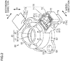
FIG. 2 is a perspective view of a housing in a state in which a lid portion of a sensor housing portion is removed in the torque sensor according to the first embodiment; -
FIG. 3 is a perspective view of the housing in a state in which the lid portion of the sensor housing portion is removed and a sensor unit is removed in the torque sensor according to the first embodiment; -
FIG. 4 illustrates a schematic configuration of a first magnetism collection ring and a second magnetism collection ring in the torque sensor according to the first embodiment; -
FIG. 5 is a top view of the first magnetism collection portion in the torque sensor according to the first embodiment; -
FIG. 6 is a schematic sectional view of the sensor housing portion in the torque sensor according to the first embodiment; -
FIG. 7 is a top view of the sensor unit in the torque sensor according to the first embodiment; -
FIG. 8 illustrates a schematic configuration of a first magnetism collection ring and a second magnetism collection ring in the torque sensor according to a second embodiment; and -
FIG. 9 is a top view of the second magnetism collection portion in the torque sensor according to the second embodiment. - A torque sensor that serves as a sensor device according to a first embodiment of the present invention will be described below. As illustrated in
FIGS. 1 to 3 , atorque sensor 1 as the sensor device includes atorsion bar 13, a cylindricalpermanent magnet 20, a cylindricalmagnetic yoke 30, a cylindricalmagnetism collection ring 40 disposed so as to surround themagnetic yoke 30, ahousing 50 that holds themagnetism collection ring 40, and asensor unit 110. Thetorque sensor 1 detects torque applied to arotary shaft 10 such as a steering shaft of an electric power steering system, for example. - The
rotary shaft 10 is composed of aninput shaft 11, anoutput shaft 12, and thetorsion bar 13. Thetorsion bar 13 that serves as a coupling shaft is disposed between theinput shaft 11 servings as a first shaft and theoutput shaft 12 serving as a second shaft. Theinput shaft 11 and theoutput shaft 12 are coupled to each other on the same axis via thetorsion bar 13. - The
permanent magnet 20 is coupled to theinput shaft 11. Thepermanent magnet 20 has acylindrical holding portion 21 and amultipole magnet 22. Theholding portion 21 is externally fitted with an end portion of theinput shaft 11 on theoutput shaft 12 side. Theholding portion 21 is attached so as to be rotatable together with theinput shaft 11. Themultipole magnet 22 is attached to the outer peripheral surface of theholding portion 21. Themultipole magnet 22 is structured such that N and S magnetic poles are disposed alternately in the circumferential direction of theholding portion 21. - The
magnetic yoke 30 is coupled to theoutput shaft 12. Themagnetic yoke 30 has an annular firstmagnetic yoke 31 and an annular secondmagnetic yoke 32. The firstmagnetic yoke 31 and the secondmagnetic yoke 32 are disposed coaxially with theoutput shaft 12, and fixed so as to be rotatable together with theoutput shaft 12. The firstmagnetic yoke 31 and the secondmagnetic yoke 32 are disposed around themultipole magnet 22 via a predetermined clearance therefrom. The firstmagnetic yoke 31 and the secondmagnetic yoke 32 are disposed in a magnetic field formed by themultipole magnet 22. The firstmagnetic yoke 31 and the secondmagnetic yoke 32 are disposed so as to face each other with a predetermined clearance therebetween in an axial direction X. The axial direction X is the axial direction of theoutput shaft 12, and is parallel to the axis of theinput shaft 11 and theoutput shaft 12. The firstmagnetic yoke 31 has a first annular portion 31a and a plurality of first lug portions 31b that extend toward the secondmagnetic yoke 32 from the inner peripheral surface of the first annular portion 31a. The first lug portions 31b are disposed at equal intervals in the circumferential direction on the inner peripheral surface of the first annular portion 31a. The secondmagnetic yoke 32 has a second annular portion 32a and a plurality ofsecond lug portions 32b that extend toward the firstmagnetic yoke 31 from the inner peripheral surface of the second annular portion 32a. Thesecond lug portions 32b are disposed at equal intervals in the circumferential direction on the inner peripheral surface of the second annular portion 32a. The firstmagnetic yoke 31 and the secondmagnetic yoke 32 are molded in asynthetic resin body 33 with the first lug portions 31b and thesecond lug portions 32b displaced from each other by a constant distance in the circumferential direction. The inner peripheral surfaces of the firstmagnetic yoke 31 and the secondmagnetic yoke 32 are exposed from thesynthetic resin body 33 to a space in the inner peripheral region. The outer peripheral surfaces of the first annular portion 31a and the second annular portion 32a are exposed from thesynthetic resin body 33 to a space in the outer peripheral region. The firstmagnetic yoke 31 and the secondmagnetic yoke 32 are constituted of a magnetic material. - In a neutral state in which the
torsion bar 13 between theinput shaft 11 and theoutput shaft 12 is not twisted, the distal ends of the first lug portions 31b of the firstmagnetic yoke 31 and the distal ends of thesecond lug portions 32b of the secondmagnetic yoke 32 point to the boundary between the N poles and the S poles of themultipole magnet 22 of thepermanent magnet 20. - The
magnetism collection ring 40 has an annular firstmagnetism collection ring 41 that guides and collects magnetism of the firstmagnetic yoke 31, and an annular secondmagnetism collection ring 42 that guides and collects magnetism of the secondmagnetic yoke 32. The firstmagnetism collection ring 41 and the secondmagnetism collection ring 42 are disposed side by side with a predetermined clearance therebetween in the axial direction X. The firstmagnetism collection ring 41 and the secondmagnetism collection ring 42 are constituted of a magnetic material. - The
housing 50 has a ringportion cover portion 60 that surrounds and holds afirst ring portion 41a of the firstmagnetism collection ring 41 and asecond ring portion 42a of the secondmagnetism collection ring 42, and asensor cover portion 70 that houses a firstmagnetism collection portion 41b of the firstmagnetism collection ring 41, a secondmagnetism collection portion 42b of the secondmagnetism collection ring 42, and thesensor unit 110. Thefirst ring portion 41a and thesecond ring portion 42a are disposed side by side in the axial direction X. The ringportion cover portion 60 and thesensor cover portion 70 are formed integrally from the same resin material. - The
sensor cover portion 70 extends toward the radially outer side from the ringportion cover portion 60. Thesensor cover portion 70 has a generally rectangular shape when seen in the axial direction X. Thesensor cover portion 70 has asensor housing portion 71 that houses thesensor unit 110 as interposed between the firstmagnetism collection portion 41b and the secondmagnetism collection portion 42b, an openingportion 72 that opens in the axial direction X, and alid portion 73 that closes the openingportion 72. Thesensor cover portion 70 extends toward the radially outer side from the ringportion cover portion 60. - As illustrated in
FIGS. 1 and4 , the secondmagnetism collection ring 42 has thesecond ring portion 42a that is disposed at the outer periphery of the secondmagnetic yoke 32 with a clearance therefrom so as to surround the secondmagnetic yoke 32, and the secondmagnetism collection portion 42b that includes a portion disposed on the radially outer side of thesecond ring portion 42a. Thesecond ring portion 42a has a secondannular portion 42c that has a C-shape, and twosecond extension portions 42d that extend toward the radially outer side from respective end portions of the secondannular portion 42c in the circumferential direction. Thesecond ring portion 42a is formed integrally with thesecond extension portions 42d. The secondmagnetism collection portion 42b is formed separately from thesecond extension portions 42d. Thesecond extension portions 42d are disposed in parallel with each other. When the secondmagnetism collection ring 42 is housed inside thehousing 50, thesecond extension portions 42d extend in a direction (hereinafter referred to as an "extension direction Z") in which thesensor cover portion 70 extends. Thesecond extension portions 42d face each other in a direction (hereinafter referred to as a "width direction Y") that is orthogonal to the direction in which thesensor cover portion 70 extends. The secondmagnetism collection portion 42b is disposed outside the secondannular portion 42c. The secondmagnetism collection portion 42b is covered by thehousing 50 with a part of the secondmagnetism collection portion 42b formed by insert molding, and disposed as interposed between thesecond extension portions 42d in the width direction Y. The secondmagnetism collection portion 42b has a secondflat plate portion 42e and secondsensor facing portions 42f that face asensor element 111 of thesensor unit 110. The longitudinal portion of the secondflat plate portion 42e has a rectangular shape to extend in the width direction Y when seen in the axial direction X. End portions of the secondflat plate portion 42e in the width direction Y are formed to be bent to extend in a direction away from the firstmagnetism collection ring 41 in the axial direction X. Portions of the secondflat plate portion 42e that extend in the axial direction X abut against thesecond extension portions 42d. - The second
sensor facing portions 42f are formed to extend in a direction closer to the secondannular portion 42c in the extension direction Z from a surface of the secondflat plate portion 42e on the secondannular portion 42c side. The secondsensor facing portions 42f have a rectangular shape when seen in the axial direction X. In the present embodiment, a pair of the secondsensor facing portions 42f are provided. The secondmagnetism collection ring 42 is constituted of a metal material. - As illustrated in
FIGS. 4 and 5 , the firstmagnetism collection ring 41 has thefirst ring portion 41a that is disposed at the outer periphery of the firstmagnetic yoke 31 with a clearance therefrom so as to surround the firstmagnetic yoke 31, and the firstmagnetism collection portion 41b that includes a portion disposed on the radially outer side of thefirst ring portion 41a. Thefirst ring portion 41a has a firstannular portion 41c that has a C-shape, and twofirst extension portions 41d that extend toward the radially outer side from respective end portions of the firstannular portion 41c in the circumferential direction. - The
first ring portion 41a is formed integrally with thefirst extension portions 41d. The firstmagnetism collection portion 41b is formed separately from thefirst extension portions 41d. Thefirst extension portions 41d are disposed in parallel with each other. When the firstmagnetism collection ring 41 is housed inside thehousing 50, thefirst extension portions 41d extend in the extension direction Z from the respective end portions of the firstannular portion 41c in the circumferential direction. Thefirst extension portions 41d face each other in the width direction Y. The firstmagnetism collection portion 41b is disposed outside the firstannular portion 41c. The firstmagnetism collection portion 41b has a firstflat plate portion 41e, firstsensor facing portions 41f that face thesensor element 111 of thesensor unit 110, and apositioning portion 43. The longitudinal portion of the firstflat plate portion 41e has a rectangular shape to extend in the width direction Y when seen in the extension direction Z. End portions of the firstflat plate portion 41e in the width direction Y are formed to be bent to extend toward the firstannular portion 41c in the extension direction Z. Portions of the firstflat plate portion 41e that extend in the extension direction Z abut against thefirst extension portions 41d. The positioningportion 43 is disposed on the radially outer side of the firstannular portion 41c with respect to thefirst extension portions 41d in the extension direction Z. The firstsensor facing portions 41f extend from the firstflat plate portion 41e toward the secondmagnetism collection portion 42b in the axial direction X, and are formed to be bent to extend toward the firstannular portion 41c in the extension direction Z. The firstsensor facing portions 41f have a rectangular shape when seen in the axial direction X. In the present embodiment, a pair of firstsensor facing portions 41f are provided. The firstsensor facing portions 41f and the secondsensor facing portions 42f face each other in the axial direction X with thesensor unit 110 disposed therebetween. The positioningportion 43 is formed to extend away from the firstannular portion 41c in the extension direction Z, and has asmall plate portion 43a and alarge plate portion 43b arranged in this order from the base end side toward the distal end side. Thesmall plate portion 43a is formed to be smaller in the width direction Y than thelarge plate portion 43b. A second throughhole 43c is provided in the center portion of thelarge plate portion 43b to penetrate in the axial direction X. The firstsensor facing portions 41f are disposed on the secondmagnetism collection portion 42b side with respect to thepositioning portion 43 in the axial direction X. The firstmagnetism collection ring 41 is constituted of a metal material. - As illustrated in
FIGS. 1 and6 , when thefirst ring portion 41a of the firstmagnetism collection ring 41 is disposed at the outer periphery of the firstmagnetic yoke 31 and thesecond ring portion 42a of the secondmagnetism collection ring 42 is disposed at the outer periphery of the secondmagnetic yoke 32, the firstsensor facing portions 41f of the firstmagnetism collection portion 41b and the secondsensor facing portions 42f of the secondmagnetism collection portion 42b are disposed so as to face each other with a predetermined clearance therebetween in the axial direction X. - As illustrated in
FIGS. 1 to 3 and6 , the ringportion cover portion 60 has a generally cylindrical shape so as to surround both the firstannular portion 41c of thefirst ring portion 41a and the secondannular portion 42c of thesecond ring portion 42a. The ringportion cover portion 60 is formed with a throughhole 61 that penetrates in the axial direction X. The firstannular portion 41c of thefirst ring portion 41a and the secondannular portion 42c of thesecond ring portion 42a are exposed to a space on the inner peripheral side of the throughhole 61 of the ringportion cover portion 60. Therotary shaft 10, thepermanent magnet 20, and themagnetic yoke 30 are disposed on the inner peripheral side of the throughhole 61 of the ringportion cover portion 60. Themagnetic yoke 30 coupled to theoutput shaft 12 is disposed on the outer peripheral side of thepermanent magnet 20 coupled to theinput shaft 11. When therotary shaft 10 is inserted through the throughhole 61 of the ringportion cover portion 60, the firstannular portion 41c of thefirst ring portion 41a faces the firstmagnetic yoke 31 and the secondannular portion 42c of thesecond ring portion 42a faces the secondmagnetic yoke 32 in the radial direction of theoutput shaft 12. The ringportion cover portion 60 has aflange portion 62 that overhangs outward from the outer peripheral surface thereof over the entire circumference. The overhanging length of theflange portion 62 is constant over the entire circumference. The ringportion cover portion 60 has a pair ofattachment portions 63 that overhang outward from the outer peripheral surface of theflange portion 62. Theattachment portions 63 are provided on respective sides of theflange portion 62 in the width direction Y. Theattachment portions 63 are provided with attachment holes 64 that penetrate in the axial direction X. The attachment holes 64 are used for attachment to an object for attachment such as a housing of an electric power steering system. Fixing materials such as screws (not illustrated) are inserted through the attachment holes 64 to attach the ringportion cover portion 60 to the object for attachment. - The
sensor housing portion 71 of thesensor cover portion 70 has abottom wall 74 on which thesensor unit 110 is placed, and aside wall 75 that separates a space inside thesensor housing portion 71 and the outside from each other. A part of thefirst extension portions 41d and a part of thesecond extension portions 42d are exposed to theside wall 75. Thebottom wall 74 has a firstbottom wall portion 74a and a secondbottom wall portion 74b arranged in this order from the base end side toward the distal end side in the extension direction Z. The secondbottom wall portion 74b is formed to be smaller in the width direction Y and smaller in the extension direction Z than the firstbottom wall portion 74a. The firstbottom wall portion 74a is formed integrally with aplacement portion 74c that projects in the axial direction X from the firstbottom wall portion 74a toward the openingportion 72. Theplacement portion 74c has an elliptical column shape. Theplacement portion 74c has an elliptical cross-sectional shape in a direction that is orthogonal to the axial direction X. Theplacement portion 74c is formed integrally with aprojection portion 76 that projects in the axial direction X from the top surface of theplacement portion 74c toward the openingportion 72. Theprojection portion 76 has a circular column shape. A plurality ofsignal terminals 77 that extend in the axial direction X are exposed to the secondbottom wall portion 74b. Aconnector portion 78 for connection with an external device is provided on a surface of thesensor housing portion 71 on the opposite side from the openingportion 72. Thesignal terminals 77 are electrically connected to theconnector portion 78. The top surface of theplacement portion 74c functions as a bottom wall portion of thesensor housing portion 71 on which acircuit board 112 to be discussed later is to be disposed. - The
lid portion 73 has afirst lid portion 73a and a second lid portion 73b arranged in this order from the base end side toward the distal end side in the extension direction Z. The second lid portion 73b is formed to be smaller in the width direction Y and smaller in the extension direction Z than thefirst lid portion 73a. Thelid portion 73 is fitted with the openingportion 72 to close the openingportion 72. - The
sensor unit 110 will be described. As illustrated inFIGS. 2 and7 , thesensor unit 110 has thesensor element 111 and thecircuit board 112 to which thesensor element 111 is connected. When thesensor unit 110 is housed in thesensor housing portion 71, thecircuit board 112 has a first circuit board portion 112a and a secondcircuit board portion 112b arranged in this order from the base end side toward the distal end side in the extension direction Z. The secondcircuit board portion 112b is formed to be smaller in the width direction Y and smaller in the extension direction Z than the first circuit board portion 112a. When thesensor unit 110 is housed in thesensor housing portion 71, a pair ofnotches 112c are provided at an end portion of the first circuit board portion 112a on the base end side in the extension direction Z. Thenotches 112c have a rectangular shape when thecircuit board 112 is seen in the axial direction X. Thesensor element 111 has a rectangular parallelepiped shape, for example. A magnetism detection element such as a Hall element, for example, is adopted as thesensor element 111. In the present embodiment, thesensor element 111 includes two sensor elements, namely afirst sensor element 111a and asecond sensor element 111b, provided redundantly. Thefirst sensor element 111a and thesecond sensor element 111b are disposed side by side in the width direction Y. Thefirst sensor element 111a and thesecond sensor element 111b are formed to be larger than thenotches 112c when seen in the axial direction X. Thefirst sensor element 111a and thesecond sensor element 111b are mounted at positions overlapping thenotches 112c when seen in the axial direction X. When thefirst sensor element 111a and thesecond sensor element 111b are mounted on thecircuit board 112, thefirst sensor element 111a and thesecond sensor element 111b are mounted on a surface of thecircuit board 112 on the secondmagnetism collection portion 42b side. The secondcircuit board portion 112b is formed with a plurality ofterminal holes 114 that penetrate in the axial direction X. No electronic components are mounted on a portion of the first circuit board portion 112a on the distal end side in the extension direction Z, that is, a portion of thecircuit board 112 between thenotches 112c and the terminal holes 114, and this portion is formed with a first throughhole 113. The first throughhole 113 penetrates in the axial direction X. The inside diameter of the first throughhole 113 is set to be equal to the inside diameter of the second throughhole 43c of thepositioning portion 43. - As illustrated in
FIGS. 3 and6 , portions of thefirst extension portions 41d on the firstannular portion 41c side in the extension direction Z are embedded in theside wall 75, and portions thereof on the opposite side from the firstannular portion 41c in the extension direction Z are exposed in thesensor housing portion 71. Thesecond extension portions 42d are covered by the firstbottom wall portion 74a except for surfaces of thesecond extension portions 42d on the openingportion 72 side, and the surfaces of thesecond extension portions 42d on the openingportion 72 side are exposed in thesensor housing portion 71. The secondmagnetism collection portion 42b is covered by the firstbottom wall portion 74a except for a surface of the secondmagnetism collection portion 42b on the openingportion 72 side, and the surface of the secondmagnetism collection portion 42b on the openingportion 72 side is exposed in thesensor housing portion 71. - As illustrated in
FIGS. 2 ,3 , and6 , when thecircuit board 112 on which thesensor element 111 is mounted is assembled to thesensor housing portion 71, theprojection portion 76 has ashaft portion 76a that extends in the axial direction X, and ahead portion 76b provided at the distal end portion of theshaft portion 76a. Theshaft portion 76a has a circular column shape. Theshaft portion 76a is inserted through the first throughhole 113 of thecircuit board 112 and the second throughhole 43c of thepositioning portion 43 of the firstmagnetism collection portion 41b. Thehead portion 76b has a hemispherical shape. The outer peripheral surface of thehead portion 76b is increased in diameter compared to theshaft portion 76a. Thehead portion 76b has a circular shape when seen in the axial direction X. The outside diameter of thehead portion 76b is set to be larger than the inside diameter of the first throughhole 113 and the inside diameter of the second throughhole 43c. The bottom surface of thehead portion 76b abuts against a surface of thepositioning portion 43 of the firstmagnetism collection portion 41b on the openingportion 72 side. - The
head portion 76b of theprojection portion 76 is not formed before thecircuit board 112 on which thesensor element 111 is mounted is assembled to thesensor housing portion 71, that is, when theprojection portion 76 is only inserted through the first throughhole 113 of thecircuit board 112 and the second throughhole 43c of thepositioning portion 43. Thehead portion 76b is formed by applying heat staking to the distal end portion of theprojection portion 76 after theprojection portion 76 is inserted through the first throughhole 113 of thecircuit board 112 and the second throughhole 43 c of thepositioning portion 43. Consequently, thecircuit board 112 and the firstmagnetism collection portion 41b are assembled to thesensor housing portion 71. - An injection molding method for the
housing 50 and a method of assembling thesensor unit 110 and the firstmagnetism collection portion 41b to thehousing 50 will be described. A die clamping process is performed by disposing thefirst ring portion 41a of the firstmagnetism collection ring 41, thesecond ring portion 42a and the secondmagnetism collection portion 42b of the secondmagnetism collection ring 42, and thesignal terminals 77 in a die (not illustrated) to be clamped in the die. After the die clamping process is performed, an injection process is performed by injecting a molten resin melted by heating from an injection device (not illustrated) into the die to fill the die with the molten resin. After the injection process is performed, a pressure holding process is performed by keeping a primary molding pressure, which is the pressure of the molten resin injected into the die, constant. By performing the pressure holding process, air bubbles etc. that remain in the molten resin are removed to suppress occurrence of a void, and the molten resin is spread throughout in the die. When the molten resin injected into the die is cooled, the molten resin is solidified so as to cover thefirst ring portion 41a, thesecond ring portion 42a, the secondmagnetism collection portion 42b, and thesignal terminals 77. In this case, the molten resin is solidified with the molten resin covering portions of thefirst extension portions 41d on the firstannular portion 41c side in the extension direction Z, outer surfaces of thesecond extension portions 42d excluding surfaces thereof on the openingportion 72 side, and outer surfaces of the secondmagnetism collection portion 42b excluding a surface thereof on the openingportion 72 side. Consequently, thehousing 50 is formed by injection molding. - After the
sensor cover portion 70 of thehousing 50 is molded, thecircuit board 112 on which thesensor element 111 is mounted is housed in thesensor housing portion 71 via the openingportion 72, and theprojection portion 76 provided in thesensor housing portion 71 is inserted through the first throughhole 113 of thecircuit board 112 and the second throughhole 43c of thepositioning portion 43 of the firstmagnetism collection portion 41b. Consequently, a surface of thecircuit board 112 on which thesensor element 111 is mounted abuts against the entire top surface of theplacement portion 74c. The entire surface of thepositioning portion 43 of the firstmagnetism collection portion 41b on the secondmagnetism collection portion 42b side abuts against a surface of thecircuit board 112 on which thesensor element 111 is not mounted. When theprojection portion 76 is inserted through the first throughhole 113 of thecircuit board 112, thesignal terminals 77 are inserted through theterminal holes 114 of thecircuit board 112, and the secondsensor facing portions 42f face thesensor element 111 mounted on thecircuit board 112. When theprojection portion 76 is inserted through the first throughhole 113 of thecircuit board 112 and the second throughhole 43c of thepositioning portion 43, the firstsensor facing portions 41f face thenotches 112c of thecircuit board 112 in the width direction Y and the extension direction Z, and the firstsensor facing portions 41f face thesensor element 111 mounted on thecircuit board 112 in the axial direction X. Thehead portion 76b is formed on theprojection portion 76 by applying heat staking to the distal end portion of theprojection portion 76 in this state. Consequently, thecircuit board 112 and the firstmagnetism collection portion 41b are not movable in the axial direction X with respect to thesensor housing portion 71, which regulates thecircuit board 112 and the firstmagnetism collection portion 41b slipping off from theprojection portion 76. The openingportion 72 is closed by fitting thelid portion 73 with the openingportion 72 after thecircuit board 112 and the firstmagnetism collection portion 41b are assembled to thesensor housing portion 71 in this manner. Consequently, assembly of thetorque sensor 1 is completed. - In the thus configured
torque sensor 1, when therotary shaft 10 is rotationally operated, for example, to cause relative rotational displacement between theinput shaft 11 and theoutput shaft 12, the positional relationship of thepermanent magnet 20 with the firstmagnetic yoke 31 and with the secondmagnetic yoke 32 is varied, and therefore magnetism collected by the firstmagnetic yoke 31 and the secondmagnetic yoke 32 is varied. Consequently, magnetism that passes between the firstmagnetism collection portion 41b and the secondmagnetism collection portion 42b is varied, and therefore the intensity of magnetism applied to thesensor element 111 is varied. The intensity of magnetism applied to thesensor element 111 is varied in accordance with the torsional angle of thetorsion bar 13. Thus, the torsional angle of thetorsion bar 13 can be computed on the basis of a detection signal output from thesensor element 111, and therefore torque applied to therotary shaft 10 can be computed on the basis of the torsional angle of thetorsion bar 13. - The functions and the effects of the first embodiment will be described.
- (1) When the
housing 50 is formed by insert molding so as to integrally surround thefirst ring portion 41a and thesecond ring portion 42a, thesensor cover portion 70 configured to house thesensor element 111 as interposed between the firstsensor facing portions 41f of the firstmagnetism collection portion 41b and the secondsensor facing portions 42f of the secondmagnetism collection portion 42b is molded. After thesensor cover portion 70 is molded, thesensor element 111 is housed in thesensor housing portion 71 via the openingportion 72, and the openingportion 72 is closed by thelid portion 73. Thus, when thehousing 50 is formed by insert molding, a molding pressure applied to form thehousing 50 by insert molding does not act to fluctuate the positional relationship between the firstsensor facing portions 41f of the firstmagnetism collection portion 41b and thesensor element 111 and the positional relationship between the secondsensor facing portions 42f of the secondmagnetism collection portion 42b and thesensor element 111. - (2) After the
sensor cover portion 70 is molded, thecircuit board 112 on which thesensor element 111 is mounted is housed in thesensor housing portion 71 via the openingportion 72, and theprojection portion 76 is inserted through the first throughhole 113 of thecircuit board 112. Consequently, a surface of thecircuit board 112 on which thesensor element 111 is mounted abuts against the top surface of theplacement portion 74c, and a surface of thecircuit board 112 on which thesensor element 111 is not mounted abuts against a surface of thepositioning portion 43 of the firstmagnetism collection portion 41b on the secondmagnetism collection portion 42b side. Thecircuit board 112 is assembled to thesensor housing portion 71 in this manner. Theprojection portion 76 is provided on thebottom wall 74 of thesensor housing portion 71. Therefore, the position of assembly of thesensor element 111 to thesensor housing portion 71 can be determined by inserting theprojection portion 76 through the first throughhole 113 of thecircuit board 112. - (3) The first
magnetism collection portion 41b is formed separately from thefirst ring portion 41a. Thus, thecircuit board 112 can be assembled with the firstmagnetism collection portion 41b removed when thecircuit board 112 on which thesensor element 111 is mounted is housed in thesensor housing portion 71 via the openingportion 72. After thecircuit board 112 is assembled to thesensor housing portion 71, the firstmagnetism collection portion 41b can be assembled such that end portions of the firstflat plate portion 41e of the firstmagnetism collection portion 41b in the width direction Y face thefirst extension portions 41d. Thus, thecircuit board 112 and the firstmagnetism collection portion 41b can be easily installed in thesensor housing portion 71. Both the position of assembly of the firstmagnetism collection portion 41b to thefirst ring portion 41a and the position of assembly of the firstmagnetism collection portion 41b to thesensor element 111 can be determined by inserting theprojection portion 76 through the second throughhole 43c provided in thepositioning portion 43 of the firstmagnetism collection portion 41b. - (4) In a comparative example, in the case where a housing is formed by injection molding with the
sensor unit 110 interposed between a first holder and a second holder, a space in which thesensor unit 110 is to be disposed is formed between the first holder and the second holder. Thus, a first magnetism collection portion and a second magnetism collection portion are occasionally deformed with the first holder and the second holder deformed so as to be collapsed by a molding pressure applied during the injection molding of the housing. In the first embodiment, thefirst extension portion 41d and thesecond extension portion 42d are formed by insert molding while abutting against a die for molding thehousing 50. Thus, thefirst extension portion 41d and thesecond extension portion 42d are not easily deformable. From the above, it is possible to suppress fluctuations in the position of assembly of the firstmagnetism collection portion 41b, which is disposed between thefirst extension portions 41d, to thesensor element 111 and the position of assembly of the secondmagnetism collection portion 42b, which is disposed between thesecond extension portions 42d, to thesensor element 111.
A torque sensor according to a second embodiment will be described. Differences from the first embodiment will be mainly described.
As illustrated inFIG. 8 , the secondmagnetism collection ring 42 has asecond ring portion 42a disposed at the outer periphery of the secondmagnetic yoke 32 with a clearance therefrom so as to surround the secondmagnetic yoke 32, and secondmagnetism collection portions 42b that extend toward the radially outer side from thesecond ring portion 42a. Thesecond ring portion 42a has a C-shape. The secondmagnetism collection portions 42b are formed integrally with thesecond ring portion 42a. The secondmagnetism collection portions 42b are formed at the middle portion of thesecond ring portion 42a in the circumferential direction. The secondmagnetism collection portions 42b extend toward thefirst ring portion 41a from a surface of thesecond ring portion 42a on thefirst ring portion 41a side, and are formed to be bent to extend in the extension direction Z. Portions of the secondmagnetism collection portions 42b that extend in the extension direction Z have a generally rectangular shape when seen in the axial direction X. The portions of the secondmagnetism collection portions 42b that extend in the extension direction Z are secondsensor facing portions 42f that face thesensor element 111 in the axial direction X. In the present embodiment, a pair of the secondsensor facing portions 42f are provided. The secondmagnetism collection ring 42 is constituted of a metal material.
As illustrated inFIGS. 8 and 9 , the firstmagnetism collection ring 41 has afirst ring portion 41a that is disposed at the outer periphery of the firstmagnetic yoke 31 with a clearance therefrom so as to surround the firstmagnetic yoke 31, and a firstmagnetism collection portion 41b that extends toward the radially outer side from thefirst ring portion 41a. Thefirst ring portion 41a has a C-shape. The firstmagnetism collection portion 41b is formed separately from thefirst ring portion 41a, and disposed on the radially outer side of thefirst ring portion 41a with a predetermined clearance from thefirst ring portion 41a. The firstmagnetism collection portion 41b is disposed on the radially outer side at the middle portion of thefirst ring portion 41a in the circumferential direction. The firstmagnetism collection portion 41b has a ring portion facing portion 41g, firstsensor facing portions 41f, and thepositioning portion 43. The ring portion facing portion 41g has a generally arcuate plate shape along thefirst ring portion 41a. The middle portion of the ring portion facing portion 41g in the circumferential direction is formed to be bent away from thefirst ring portion 41a compared to both end portions of the ring portion facing portion 41g in the circumferential direction. The firstsensor facing portions 41f extend in the axial direction X from the middle portion of the ring portion facing portion 41g in the circumferential direction toward thesecond ring portion 42a, and are formed to be bent to extend in the extension direction Z in the direction away from thefirst ring portion 41a. The firstsensor facing portions 41f have a generally rectangular shape when seen in the axial direction X. In the present embodiment, a pair of the firstsensor facing portions 41f are provided. The firstsensor facing portions 41f and the secondsensor facing portions 42f face each other in the axial direction X with thesensor element 111 disposed therebetween. The direction in which the firstsensor facing portions 41f and the secondsensor facing portions 42f face each other coincides with the axial direction X. The positioningportion 43 is provided between the two firstsensor facing portions 41f in the width direction Y. The positioningportion 43 has thesmall plate portion 43a and thelarge plate portion 43b arranged in this order from the base end side toward the distal end side in the extension direction Z. Thesmall plate portion 43a is formed to be smaller in the width direction Y than thelarge plate portion 43b. A second throughhole 43c is provided in the center portion of thelarge plate portion 43b to penetrate in the axial direction X. The firstmagnetism collection ring 41 is constituted of a metal material.
After thesensor cover portion 70 of thehousing 50 is molded, thecircuit board 112 on which thesensor element 111 is mounted is housed in thesensor housing portion 71 via the openingportion 72, and theprojection portion 76 provided in thesensor housing portion 71 is inserted through the first throughhole 113 of thecircuit board 112 and the second throughhole 43c of thepositioning portion 43 of the firstmagnetism collection portion 41b. A surface of thecircuit board 112 on which thesensor element 111 is not mounted abuts against the entire top surface of theplacement portion 74c. The entire surface of thepositioning portion 43 of the firstmagnetism collection portion 41b on the secondmagnetism collection portion 42b side abuts against a surface of thecircuit board 112 on which thesensor element 111 is mounted. When theprojection portion 76 is inserted through the first throughhole 113 of thecircuit board 112 and the second throughhole 43c of thepositioning portion 43, thesignal terminals 77 are inserted through theterminal holes 114 of thecircuit board 112, and the secondsensor facing portions 42f of the secondmagnetism collection portion 42b are inserted into thenotches 112c of thecircuit board 112. Thus, the secondsensor facing portions 42f face thesensor element 111 that is mounted on thecircuit board 112. When theprojection portion 76 is inserted through the first throughhole 113 of thecircuit board 112 and the second throughhole 43c of thepositioning portion 43, the firstsensor facing portions 41f face thesensor element 111 that is mounted on thecircuit board 112. The openingportion 72 is closed by fitting thelid portion 73 with the openingportion 72 after thecircuit board 112 and the firstmagnetism collection portion 41b are assembled to thesensor housing portion 71 in this manner. Consequently, assembly of thetorque sensor 1 is completed.
The functions and the effects of the second embodiment will be described. - (5) The first
magnetism collection portion 41b is formed separately and away from thefirst ring portion 41a in the radial direction. Thus, thecircuit board 112 can be assembled to thesensor housing portion 71 with the firstmagnetism collection portion 41b removed when thecircuit board 112 on which thesensor element 111 is mounted is housed in thesensor housing portion 71 via the openingportion 72. After thecircuit board 112 is assembled to thesensor housing portion 71, the positioningportion 43 of the firstmagnetism collection portion 41b can be assembled to thesensor housing portion 71 such that the ring portion facing portion 41g of the firstmagnetism collection portion 41b and thefirst ring portion 41a face each other with a predetermined clearance therebetween. Thus, thecircuit board 112 and the firstmagnetism collection portion 41b can be easily installed in thesensor housing portion 71. Both the position of assembly of the firstmagnetism collection portion 41b to thefirst ring portion 41a and the position of assembly of the firstmagnetism collection portion 41b to thesensor element 111 can be determined by inserting theprojection portion 76 through the second throughhole 43c that is provided in thepositioning portion 43 of the firstmagnetism collection portion 41b. - The embodiments may be modified as follows. The following other embodiments may be combined with each other as long as the embodiments do not technically contradict with each other. In the first embodiment, the
second ring portion 42a and the secondmagnetism collection portion 42b may be formed integrally with each other. - In the first embodiment, the
first ring portion 41a and the firstmagnetism collection portion 41b may be formed integrally with each other if thesensor element 111 can be disposed between the firstmagnetism collection portion 41b and the secondmagnetism collection portion 42b. In this case, thecircuit board 112 on which thesensor element 111 is mounted is disposed by being inserted into a space between the firstmagnetism collection portion 41b and the secondmagnetism collection portion 42b in the extension direction Z, for example. - In the second embodiment, the
second ring portion 42a and the secondmagnetism collection portion 42b may be formed separately from each other. In the second embodiment, thefirst ring portion 41a and the firstmagnetism collection portion 41b may be formed integrally with each other if thesensor element 111 can be disposed between the firstmagnetism collection portion 41b and the secondmagnetism collection portion 42b. - In the first embodiment, the
first extension portions 41d may not be provided. In this case, the firstmagnetism collection portion 41b is disposed between end portions of the firstannular portion 41c in the circumferential direction. The secondsensor facing portions 42f may extend from a surface of the secondflat plate portion 42e on the firstmagnetism collection portion 41b side toward the firstmagnetism collection portion 41b, and be formed to be bent to extend toward the secondannular portion 42c in the extension direction Z. In this case, the secondsensor facing portions 42f face thenotches 112c of thecircuit board 112 in the width direction Y and the extension direction Z by inserting theprojection portion 76 through the first throughhole 113 of thecircuit board 112 and the second throughhole 43c of thepositioning portion 43. - During injection molding of the
housing 50, an injection process may be performed without disposing the secondmagnetism collection portion 42b in the die. In this case, a recess for placement of the secondmagnetism collection portion 42b may be formed in the firstbottom wall portion 74a of thehousing 50 that is formed by the injection molding, and the secondmagnetism collection portion 42b may be placed in the recess. The secondmagnetism collection portion 42b and thesecond extension portions 42d may be connected to each other in the width direction Y by welding or the like. The secondmagnetism collection portion 42b may be placed in a recess formed in the firstbottom wall portion 74a for placement of the secondmagnetism collection portion 42b, and the secondflat plate portion 42e and thesecond extension portions 42d of the secondmagnetism collection portion 42b may be connected to each other in the width direction Y by welding or the like. - The first
magnetism collection portion 41b is assembled to thesensor housing portion 71 by inserting theprojection portion 76 through the second throughhole 43c of thepositioning portion 43. However, the present invention is not limited thereto. For example, the firstmagnetism collection portion 41b may be assembled to thesensor housing portion 71 by connecting the firstflat plate portion 41e of the firstmagnetism collection portion 41b and thesecond extension portions 42d in the width direction Y by welding or the like. - In the first embodiment, the second
magnetism collection portion 42b in the plate thickness direction is entirely covered by the firstbottom wall portion 74a so that only a surface of the secondmagnetism collection portion 42b on the openingportion 72 side is exposed in thesensor housing portion 71. However, the present invention is not limited thereto. For example, a part of the secondmagnetism collection portion 42b in the plate thickness direction may be covered by the firstbottom wall portion 74a so that not only a surface of the secondmagnetism collection portion 42b on the openingportion 72 side but also a part of a surface of the secondmagnetism collection portion 42b in the extension direction Z is exposed in thesensor housing portion 71. - The first
magnetism collection portion 41b is assembled to thesensor housing portion 71 by applying heat staking to theprojection portion 76 that is inserted through the second throughhole 43c of thepositioning portion 43. However, the present invention is not limited thereto. For example, the firstmagnetism collection portion 41b may be assembled to thesensor housing portion 71 using a screw. Alternatively, the firstmagnetism collection portion 41b may be assembled to thesensor housing portion 71 with a snap-fit lug extending from thesensor housing portion 71 engaged with a snap-fit hole provided in the firstmagnetism collection portion 41b. In this case, the firstmagnetism collection portion 41b may not be provided with thepositioning portion 43. That is, the method of fixing the firstmagnetism collection portion 41b to thesensor housing portion 71 is changeable as appropriate. - While the
projection portion 76 is formed with thehead portion 76b, thehead portion 76b may not be provided. That is, it is only necessary that theprojection portion 76 should include at least theshaft portion 76a. For example, theprojection portion 76 may be positioned by sliding contact between the first throughhole 113 and the second throughhole 43c. In this case, a process of forming thehead portion 76b by applying heat staking to the distal end portion of theprojection portion 76 may be omitted. - While the
shaft portion 76a has a circular column shape, theshaft portion 76a may have a polygonal column shape. Two or more of theprojection portions 76 may be provided. Thecircuit board 112 is disposed on the top surface of theplacement portion 74c. However, the present invention is not limited thereto. For example, thecircuit board 112 may be disposed on the firstbottom wall portion 74a of thesensor housing portion 71. In this case, theprojection portion 76 is provided on the firstbottom wall portion 74a. - The first
magnetism collection ring 41 is provided with two the firstsensor facing portions 41f, and the secondmagnetism collection ring 42 is provided with two the secondsensor facing portions 42f. However, only one suchfacing portion may be provided, and three or more such facing portions may be provided. - The
sensor unit 110 may be connected to a terminal (connection terminal) that has a conductive portion that can energize thesensor element 111. While a Hall element is adopted as thesensor element 111, a magnetoresistance element may be adopted. - While the sensor device is embodied as the
torque sensor 1 that detects torque, the sensor device may be embodied as a rotational angle detection device that detects the rotational angle of therotary shaft 10, for example.
Claims (4)
- A sensor device comprising:a permanent magnet attached to a first shaft and magnetized such that N poles and S poles appear alternately in a circumferential direction on an outer peripheral surface of the permanent magnet;a magnetic yoke that is fixed to a second shaft coupled to the first shaft and is disposed in a magnetic field formed by the permanent magnet;a first magnetism collection ring that has an annular first ring portion that surrounds the magnetic yoke and a first magnetism collection portion that includes a portion disposed on a radially outer side of the first ring portion;a second magnetism collection ring disposed side by side with the first magnetism collection ring in an axial direction of the second shaft, the second magnetism collection ring having an annular second ring portion that surrounds the magnetic yoke and a second magnetism collection portion that includes a portion disposed on a radially outer side of the second ring portion;a housing formed by insert molding so as to integrally surround the first ring portion and the second ring portion; anda sensor element that detects magnetism of a magnetic circuit formed by the permanent magnet, the magnetic yoke, the first magnetism collection ring, and the second magnetism collection ring, wherein:the housing has a ring portion cover portion that integrally surrounds and holds the first ring portion and the second ring portion, and a sensor cover portion that surrounds and holds the first magnetism collection portion, the second magnetism collection portion, and the sensor element; andthe sensor cover portion houses the sensor element as interposed between the first magnetism collection portion and the second magnetism collection portion, and has an opening portion for insertion of the sensor element into the sensor cover portion covered by a lid portion.
- The sensor device according to claim 1, wherein:the opening portion of the sensor cover portion opens in the axial direction of the first shaft and the second shaft;the first magnetism collection portion and the second magnetism collection portion face each other in the axial direction inside the sensor cover portion;the sensor element is mounted on a circuit portion formed with a first through hole that penetrates in the axial direction;a projection portion is provided inside the sensor cover portion, the projection portion projecting in the axial direction from a bottom wall portion on which the circuit portion is disposed; andthe projection portion is inserted through the first through hole of the circuit portion.
- The sensor device according to claim 2, wherein:the first magnetism collection portion is positioned on a side on which the opening portion opens with respect to the second magnetism collection portion;the first magnetism collection portion is formed separately from the first ring portion, and disposed between end portions of the first ring portion, which has a C-shape, in the circumferential direction;the first magnetism collection portion is formed with a second through hole that penetrates in the axial direction; andthe projection portion is inserted through the second through hole.
- The sensor device according to claim 2, wherein:the first magnetism collection portion is positioned on a side on which the opening portion opens with respect to the second magnetism collection portion;the first magnetism collection portion is formed separately from the first ring portion, and disposed on the radially outer side of the first ring portion;the first magnetism collection portion is formed with a second through hole that penetrates in the axial direction; andthe projection portion is inserted through the second through hole.
Applications Claiming Priority (1)
| Application Number | Priority Date | Filing Date | Title |
|---|---|---|---|
| JP2018160664A JP7124566B2 (en) | 2018-08-29 | 2018-08-29 | sensor device |
Publications (2)
| Publication Number | Publication Date |
|---|---|
| EP3617684A1 true EP3617684A1 (en) | 2020-03-04 |
| EP3617684B1 EP3617684B1 (en) | 2022-04-20 |
Family
ID=67777148
Family Applications (1)
| Application Number | Title | Priority Date | Filing Date |
|---|---|---|---|
| EP19194013.9A Active EP3617684B1 (en) | 2018-08-29 | 2019-08-28 | Sensor device |
Country Status (4)
| Country | Link |
|---|---|
| US (1) | US11131593B2 (en) |
| EP (1) | EP3617684B1 (en) |
| JP (1) | JP7124566B2 (en) |
| CN (1) | CN110873617B (en) |
Families Citing this family (3)
| Publication number | Priority date | Publication date | Assignee | Title |
|---|---|---|---|---|
| JP2022130102A (en) * | 2021-02-25 | 2022-09-06 | 株式会社ジェイテクト | Magnetic shield, sensor device, and method for assembling magnetic shield |
| WO2023025379A1 (en) * | 2021-08-25 | 2023-03-02 | Thyssenkrupp Presta Ag | Sensor device for a motor vehicle steering system, steering system for a motor vehicle, and method for producing a sensor device |
| WO2023181116A1 (en) * | 2022-03-22 | 2023-09-28 | 株式会社ジェイテクト | Sensor device |
Citations (4)
| Publication number | Priority date | Publication date | Assignee | Title |
|---|---|---|---|---|
| US20030154800A1 (en) * | 2002-02-21 | 2003-08-21 | Visteon Global Technologies, Inc. | Flux brush torque sensor |
| US20160153850A1 (en) * | 2014-11-27 | 2016-06-02 | Denso Corporation | Magnetic detection device and torque sensor including the same |
| US20160214648A1 (en) * | 2012-12-13 | 2016-07-28 | Valeo Schalter Und Sensoren Gmbh | Device with a torque sensor device and a steering angle sensor device for a motor vehicle, motor vehicle and method for manufacturing a device |
| JP2018084444A (en) | 2016-11-21 | 2018-05-31 | 株式会社ジェイテクト | Torque detector and manufacturing method thereof |
Family Cites Families (20)
| Publication number | Priority date | Publication date | Assignee | Title |
|---|---|---|---|---|
| JP4656851B2 (en) * | 2004-03-18 | 2011-03-23 | 株式会社ジェイテクト | Torque detection device |
| CN101523176A (en) * | 2006-10-12 | 2009-09-02 | 日本精工株式会社 | Torque detector, method of producing the torque detector, and electric power steering device |
| JP2009092463A (en) | 2007-10-05 | 2009-04-30 | Jtekt Corp | Torque detection apparatus, its manufacturing method, and electric power steering system |
| JP5221679B2 (en) * | 2008-06-26 | 2013-06-26 | テソン エレクトリック シーオー エルティディ | Non-contact torque sensor for steering device |
| JP5243385B2 (en) * | 2009-10-20 | 2013-07-24 | 株式会社ホンダロック | Torque sensor |
| JP2012237727A (en) * | 2011-05-13 | 2012-12-06 | Denso Corp | Torque sensor |
| JP2012237728A (en) * | 2011-05-13 | 2012-12-06 | Denso Corp | Torque sensor |
| KR101863780B1 (en) * | 2011-11-29 | 2018-06-01 | 엘지이노텍 주식회사 | Torque Index Sensor |
| JP5994264B2 (en) * | 2012-02-01 | 2016-09-21 | 株式会社ジェイテクト | Torque detection device and manufacturing method thereof |
| WO2013140864A1 (en) * | 2012-03-22 | 2013-09-26 | カヤバ工業株式会社 | Torque sensor |
| JP2014029304A (en) * | 2012-07-31 | 2014-02-13 | Jtekt Corp | Torque detecting device and steering device including the same |
| JP5978876B2 (en) | 2012-09-14 | 2016-08-24 | 株式会社ジェイテクト | Torque detection device and steering device including the same |
| JP6056458B2 (en) * | 2012-12-25 | 2017-01-11 | 株式会社ジェイテクト | Torque detection device and steering device including the same |
| JP6295483B2 (en) * | 2014-09-19 | 2018-03-20 | 日立オートモティブシステムズ株式会社 | Power steering device and method of assembling power steering device |
| JP6354570B2 (en) | 2014-12-22 | 2018-07-11 | 株式会社デンソー | Sensor unit and magnetic flux collecting module using the same |
| JP6665668B2 (en) * | 2016-04-28 | 2020-03-13 | 株式会社ジェイテクト | Torque detector |
| JP6729135B2 (en) * | 2016-07-27 | 2020-07-22 | 株式会社ジェイテクト | Torque detection device and electric power steering device |
| JP2018036206A (en) * | 2016-09-01 | 2018-03-08 | 株式会社ジェイテクト | Sensor device |
| JP7115113B2 (en) * | 2018-07-27 | 2022-08-09 | 株式会社ジェイテクト | sensor device |
| JP7127417B2 (en) * | 2018-08-09 | 2022-08-30 | 株式会社ジェイテクト | sensor device |
-
2018
- 2018-08-29 JP JP2018160664A patent/JP7124566B2/en active Active
-
2019
- 2019-08-23 US US16/549,507 patent/US11131593B2/en active Active
- 2019-08-28 CN CN201910801204.8A patent/CN110873617B/en active Active
- 2019-08-28 EP EP19194013.9A patent/EP3617684B1/en active Active
Patent Citations (4)
| Publication number | Priority date | Publication date | Assignee | Title |
|---|---|---|---|---|
| US20030154800A1 (en) * | 2002-02-21 | 2003-08-21 | Visteon Global Technologies, Inc. | Flux brush torque sensor |
| US20160214648A1 (en) * | 2012-12-13 | 2016-07-28 | Valeo Schalter Und Sensoren Gmbh | Device with a torque sensor device and a steering angle sensor device for a motor vehicle, motor vehicle and method for manufacturing a device |
| US20160153850A1 (en) * | 2014-11-27 | 2016-06-02 | Denso Corporation | Magnetic detection device and torque sensor including the same |
| JP2018084444A (en) | 2016-11-21 | 2018-05-31 | 株式会社ジェイテクト | Torque detector and manufacturing method thereof |
Also Published As
| Publication number | Publication date |
|---|---|
| JP2020034398A (en) | 2020-03-05 |
| JP7124566B2 (en) | 2022-08-24 |
| CN110873617A (en) | 2020-03-10 |
| US20200072688A1 (en) | 2020-03-05 |
| CN110873617B (en) | 2024-02-13 |
| EP3617684B1 (en) | 2022-04-20 |
| US11131593B2 (en) | 2021-09-28 |
Similar Documents
| Publication | Publication Date | Title |
|---|---|---|
| EP3617684B1 (en) | Sensor device | |
| KR102397192B1 (en) | Sensor assembly and motor including the same | |
| US9071107B2 (en) | Rotor unit, rotating electrical machine, and method for manufacturing rotor unit | |
| EP2107355B1 (en) | Magnetic torque sensor | |
| US9664498B2 (en) | Variable reluctance resolver | |
| JP5786642B2 (en) | Stator fixing structure | |
| US20040183386A1 (en) | Electric motor | |
| JP2020034422A (en) | Sensor device | |
| EP3608645B1 (en) | Sensor device | |
| EP1813925B1 (en) | Torque Detection Device | |
| KR20110109100A (en) | Apparatus for detecting torque | |
| US6924576B2 (en) | Transverse flux machine, in particular a unipolar transverse flux machine | |
| US11060931B2 (en) | Sensor device | |
| JP4071484B2 (en) | Motor equipment | |
| EP3736539A1 (en) | Sensing device | |
| EP1808682A2 (en) | Torque detection device and magnet fixing method | |
| CN111566449B (en) | Sensing device | |
| KR20180127799A (en) | Stator and motor having the same | |
| JP2019030141A (en) | Connector and motor with connector | |
| CN217935257U (en) | Clamp for positioning temperature detection element | |
| JP7294093B2 (en) | Yoke member for torque detector and manufacturing method thereof | |
| JP2019030144A (en) | Connector and motor with connector | |
| JP7106051B2 (en) | Rotation detection device and method for manufacturing rotation detection device | |
| KR20210123628A (en) | Motor | |
| KR20200041141A (en) | Motor |
Legal Events
| Date | Code | Title | Description |
|---|---|---|---|
| PUAI | Public reference made under article 153(3) epc to a published international application that has entered the european phase |
Free format text: ORIGINAL CODE: 0009012 |
|
| STAA | Information on the status of an ep patent application or granted ep patent |
Free format text: STATUS: THE APPLICATION HAS BEEN PUBLISHED |
|
| AK | Designated contracting states |
Kind code of ref document: A1 Designated state(s): AL AT BE BG CH CY CZ DE DK EE ES FI FR GB GR HR HU IE IS IT LI LT LU LV MC MK MT NL NO PL PT RO RS SE SI SK SM TR |
|
| AX | Request for extension of the european patent |
Extension state: BA ME |
|
| STAA | Information on the status of an ep patent application or granted ep patent |
Free format text: STATUS: REQUEST FOR EXAMINATION WAS MADE |
|
| 17P | Request for examination filed |
Effective date: 20200518 |
|
| RBV | Designated contracting states (corrected) |
Designated state(s): AL AT BE BG CH CY CZ DE DK EE ES FI FR GB GR HR HU IE IS IT LI LT LU LV MC MK MT NL NO PL PT RO RS SE SI SK SM TR |
|
| STAA | Information on the status of an ep patent application or granted ep patent |
Free format text: STATUS: EXAMINATION IS IN PROGRESS |
|
| 17Q | First examination report despatched |
Effective date: 20201001 |
|
| STAA | Information on the status of an ep patent application or granted ep patent |
Free format text: STATUS: EXAMINATION IS IN PROGRESS |
|
| GRAP | Despatch of communication of intention to grant a patent |
Free format text: ORIGINAL CODE: EPIDOSNIGR1 |
|
| STAA | Information on the status of an ep patent application or granted ep patent |
Free format text: STATUS: GRANT OF PATENT IS INTENDED |
|
| INTG | Intention to grant announced |
Effective date: 20210611 |
|
| RIN1 | Information on inventor provided before grant (corrected) |
Inventor name: TOYAMA, YUICHI |
|
| GRAJ | Information related to disapproval of communication of intention to grant by the applicant or resumption of examination proceedings by the epo deleted |
Free format text: ORIGINAL CODE: EPIDOSDIGR1 |
|
| STAA | Information on the status of an ep patent application or granted ep patent |
Free format text: STATUS: EXAMINATION IS IN PROGRESS |
|
| GRAS | Grant fee paid |
Free format text: ORIGINAL CODE: EPIDOSNIGR3 |
|
| STAA | Information on the status of an ep patent application or granted ep patent |
Free format text: STATUS: GRANT OF PATENT IS INTENDED |
|
| GRAP | Despatch of communication of intention to grant a patent |
Free format text: ORIGINAL CODE: EPIDOSNIGR1 |
|
| INTC | Intention to grant announced (deleted) | ||
| INTG | Intention to grant announced |
Effective date: 20211112 |
|
| GRAA | (expected) grant |
Free format text: ORIGINAL CODE: 0009210 |
|
| STAA | Information on the status of an ep patent application or granted ep patent |
Free format text: STATUS: THE PATENT HAS BEEN GRANTED |
|
| RAP3 | Party data changed (applicant data changed or rights of an application transferred) |
Owner name: JTEKT CORPORATION |
|
| AK | Designated contracting states |
Kind code of ref document: B1 Designated state(s): AL AT BE BG CH CY CZ DE DK EE ES FI FR GB GR HR HU IE IS IT LI LT LU LV MC MK MT NL NO PL PT RO RS SE SI SK SM TR |
|
| RAP3 | Party data changed (applicant data changed or rights of an application transferred) |
Owner name: JTEKT CORPORATION |
|
| REG | Reference to a national code |
Ref country code: GB Ref legal event code: FG4D |
|
| REG | Reference to a national code |
Ref country code: CH Ref legal event code: EP |
|
| REG | Reference to a national code |
Ref country code: IE Ref legal event code: FG4D |
|
| REG | Reference to a national code |
Ref country code: DE Ref legal event code: R096 Ref document number: 602019013841 Country of ref document: DE |
|
| REG | Reference to a national code |
Ref country code: AT Ref legal event code: REF Ref document number: 1485492 Country of ref document: AT Kind code of ref document: T Effective date: 20220515 |
|
| REG | Reference to a national code |
Ref country code: LT Ref legal event code: MG9D |
|
| REG | Reference to a national code |
Ref country code: NL Ref legal event code: MP Effective date: 20220420 |
|
| REG | Reference to a national code |
Ref country code: AT Ref legal event code: MK05 Ref document number: 1485492 Country of ref document: AT Kind code of ref document: T Effective date: 20220420 |
|
| PG25 | Lapsed in a contracting state [announced via postgrant information from national office to epo] |
Ref country code: NL Free format text: LAPSE BECAUSE OF FAILURE TO SUBMIT A TRANSLATION OF THE DESCRIPTION OR TO PAY THE FEE WITHIN THE PRESCRIBED TIME-LIMIT Effective date: 20220420 |
|
| PG25 | Lapsed in a contracting state [announced via postgrant information from national office to epo] |
Ref country code: SE Free format text: LAPSE BECAUSE OF FAILURE TO SUBMIT A TRANSLATION OF THE DESCRIPTION OR TO PAY THE FEE WITHIN THE PRESCRIBED TIME-LIMIT Effective date: 20220420 Ref country code: PT Free format text: LAPSE BECAUSE OF FAILURE TO SUBMIT A TRANSLATION OF THE DESCRIPTION OR TO PAY THE FEE WITHIN THE PRESCRIBED TIME-LIMIT Effective date: 20220822 Ref country code: NO Free format text: LAPSE BECAUSE OF FAILURE TO SUBMIT A TRANSLATION OF THE DESCRIPTION OR TO PAY THE FEE WITHIN THE PRESCRIBED TIME-LIMIT Effective date: 20220720 Ref country code: LT Free format text: LAPSE BECAUSE OF FAILURE TO SUBMIT A TRANSLATION OF THE DESCRIPTION OR TO PAY THE FEE WITHIN THE PRESCRIBED TIME-LIMIT Effective date: 20220420 Ref country code: HR Free format text: LAPSE BECAUSE OF FAILURE TO SUBMIT A TRANSLATION OF THE DESCRIPTION OR TO PAY THE FEE WITHIN THE PRESCRIBED TIME-LIMIT Effective date: 20220420 Ref country code: GR Free format text: LAPSE BECAUSE OF FAILURE TO SUBMIT A TRANSLATION OF THE DESCRIPTION OR TO PAY THE FEE WITHIN THE PRESCRIBED TIME-LIMIT Effective date: 20220721 Ref country code: FI Free format text: LAPSE BECAUSE OF FAILURE TO SUBMIT A TRANSLATION OF THE DESCRIPTION OR TO PAY THE FEE WITHIN THE PRESCRIBED TIME-LIMIT Effective date: 20220420 Ref country code: ES Free format text: LAPSE BECAUSE OF FAILURE TO SUBMIT A TRANSLATION OF THE DESCRIPTION OR TO PAY THE FEE WITHIN THE PRESCRIBED TIME-LIMIT Effective date: 20220420 Ref country code: BG Free format text: LAPSE BECAUSE OF FAILURE TO SUBMIT A TRANSLATION OF THE DESCRIPTION OR TO PAY THE FEE WITHIN THE PRESCRIBED TIME-LIMIT Effective date: 20220720 Ref country code: AT Free format text: LAPSE BECAUSE OF FAILURE TO SUBMIT A TRANSLATION OF THE DESCRIPTION OR TO PAY THE FEE WITHIN THE PRESCRIBED TIME-LIMIT Effective date: 20220420 |
|
| PG25 | Lapsed in a contracting state [announced via postgrant information from national office to epo] |
Ref country code: RS Free format text: LAPSE BECAUSE OF FAILURE TO SUBMIT A TRANSLATION OF THE DESCRIPTION OR TO PAY THE FEE WITHIN THE PRESCRIBED TIME-LIMIT Effective date: 20220420 Ref country code: PL Free format text: LAPSE BECAUSE OF FAILURE TO SUBMIT A TRANSLATION OF THE DESCRIPTION OR TO PAY THE FEE WITHIN THE PRESCRIBED TIME-LIMIT Effective date: 20220420 Ref country code: LV Free format text: LAPSE BECAUSE OF FAILURE TO SUBMIT A TRANSLATION OF THE DESCRIPTION OR TO PAY THE FEE WITHIN THE PRESCRIBED TIME-LIMIT Effective date: 20220420 Ref country code: IS Free format text: LAPSE BECAUSE OF FAILURE TO SUBMIT A TRANSLATION OF THE DESCRIPTION OR TO PAY THE FEE WITHIN THE PRESCRIBED TIME-LIMIT Effective date: 20220820 |
|
| REG | Reference to a national code |
Ref country code: DE Ref legal event code: R097 Ref document number: 602019013841 Country of ref document: DE |
|
| PG25 | Lapsed in a contracting state [announced via postgrant information from national office to epo] |
Ref country code: SM Free format text: LAPSE BECAUSE OF FAILURE TO SUBMIT A TRANSLATION OF THE DESCRIPTION OR TO PAY THE FEE WITHIN THE PRESCRIBED TIME-LIMIT Effective date: 20220420 Ref country code: SK Free format text: LAPSE BECAUSE OF FAILURE TO SUBMIT A TRANSLATION OF THE DESCRIPTION OR TO PAY THE FEE WITHIN THE PRESCRIBED TIME-LIMIT Effective date: 20220420 Ref country code: RO Free format text: LAPSE BECAUSE OF FAILURE TO SUBMIT A TRANSLATION OF THE DESCRIPTION OR TO PAY THE FEE WITHIN THE PRESCRIBED TIME-LIMIT Effective date: 20220420 Ref country code: EE Free format text: LAPSE BECAUSE OF FAILURE TO SUBMIT A TRANSLATION OF THE DESCRIPTION OR TO PAY THE FEE WITHIN THE PRESCRIBED TIME-LIMIT Effective date: 20220420 Ref country code: DK Free format text: LAPSE BECAUSE OF FAILURE TO SUBMIT A TRANSLATION OF THE DESCRIPTION OR TO PAY THE FEE WITHIN THE PRESCRIBED TIME-LIMIT Effective date: 20220420 Ref country code: CZ Free format text: LAPSE BECAUSE OF FAILURE TO SUBMIT A TRANSLATION OF THE DESCRIPTION OR TO PAY THE FEE WITHIN THE PRESCRIBED TIME-LIMIT Effective date: 20220420 |
|
| PLBE | No opposition filed within time limit |
Free format text: ORIGINAL CODE: 0009261 |
|
| STAA | Information on the status of an ep patent application or granted ep patent |
Free format text: STATUS: NO OPPOSITION FILED WITHIN TIME LIMIT |
|
| 26N | No opposition filed |
Effective date: 20230123 |
|
| PG25 | Lapsed in a contracting state [announced via postgrant information from national office to epo] |
Ref country code: MC Free format text: LAPSE BECAUSE OF FAILURE TO SUBMIT A TRANSLATION OF THE DESCRIPTION OR TO PAY THE FEE WITHIN THE PRESCRIBED TIME-LIMIT Effective date: 20220420 Ref country code: AL Free format text: LAPSE BECAUSE OF FAILURE TO SUBMIT A TRANSLATION OF THE DESCRIPTION OR TO PAY THE FEE WITHIN THE PRESCRIBED TIME-LIMIT Effective date: 20220420 |
|
| REG | Reference to a national code |
Ref country code: CH Ref legal event code: PL |
|
| PG25 | Lapsed in a contracting state [announced via postgrant information from national office to epo] |
Ref country code: LU Free format text: LAPSE BECAUSE OF NON-PAYMENT OF DUE FEES Effective date: 20220828 Ref country code: LI Free format text: LAPSE BECAUSE OF NON-PAYMENT OF DUE FEES Effective date: 20220831 Ref country code: CH Free format text: LAPSE BECAUSE OF NON-PAYMENT OF DUE FEES Effective date: 20220831 |
|
| REG | Reference to a national code |
Ref country code: BE Ref legal event code: MM Effective date: 20220831 |
|
| PG25 | Lapsed in a contracting state [announced via postgrant information from national office to epo] |
Ref country code: SI Free format text: LAPSE BECAUSE OF FAILURE TO SUBMIT A TRANSLATION OF THE DESCRIPTION OR TO PAY THE FEE WITHIN THE PRESCRIBED TIME-LIMIT Effective date: 20220420 |
|
| PG25 | Lapsed in a contracting state [announced via postgrant information from national office to epo] |
Ref country code: IE Free format text: LAPSE BECAUSE OF NON-PAYMENT OF DUE FEES Effective date: 20220828 |
|
| PG25 | Lapsed in a contracting state [announced via postgrant information from national office to epo] |
Ref country code: BE Free format text: LAPSE BECAUSE OF NON-PAYMENT OF DUE FEES Effective date: 20220831 |
|
| PGFP | Annual fee paid to national office [announced via postgrant information from national office to epo] |
Ref country code: FR Payment date: 20230703 Year of fee payment: 5 Ref country code: DE Payment date: 20230703 Year of fee payment: 5 |
|
| PG25 | Lapsed in a contracting state [announced via postgrant information from national office to epo] |
Ref country code: IT Free format text: LAPSE BECAUSE OF FAILURE TO SUBMIT A TRANSLATION OF THE DESCRIPTION OR TO PAY THE FEE WITHIN THE PRESCRIBED TIME-LIMIT Effective date: 20220420 |
|
| PG25 | Lapsed in a contracting state [announced via postgrant information from national office to epo] |
Ref country code: HU Free format text: LAPSE BECAUSE OF FAILURE TO SUBMIT A TRANSLATION OF THE DESCRIPTION OR TO PAY THE FEE WITHIN THE PRESCRIBED TIME-LIMIT; INVALID AB INITIO Effective date: 20190828 |