WO2013140864A1 - Torque sensor - Google Patents
Torque sensor Download PDFInfo
- Publication number
- WO2013140864A1 WO2013140864A1 PCT/JP2013/052257 JP2013052257W WO2013140864A1 WO 2013140864 A1 WO2013140864 A1 WO 2013140864A1 JP 2013052257 W JP2013052257 W JP 2013052257W WO 2013140864 A1 WO2013140864 A1 WO 2013140864A1
- Authority
- WO
- WIPO (PCT)
- Prior art keywords
- magnetic
- ring
- torque sensor
- magnetism collecting
- magnetism
- Prior art date
Links
Images


Classifications
-
- G—PHYSICS
- G01—MEASURING; TESTING
- G01L—MEASURING FORCE, STRESS, TORQUE, WORK, MECHANICAL POWER, MECHANICAL EFFICIENCY, OR FLUID PRESSURE
- G01L3/00—Measuring torque, work, mechanical power, or mechanical efficiency, in general
- G01L3/02—Rotary-transmission dynamometers
- G01L3/04—Rotary-transmission dynamometers wherein the torque-transmitting element comprises a torsionally-flexible shaft
- G01L3/10—Rotary-transmission dynamometers wherein the torque-transmitting element comprises a torsionally-flexible shaft involving electric or magnetic means for indicating
- G01L3/101—Rotary-transmission dynamometers wherein the torque-transmitting element comprises a torsionally-flexible shaft involving electric or magnetic means for indicating involving magnetic or electromagnetic means
-
- B—PERFORMING OPERATIONS; TRANSPORTING
- B62—LAND VEHICLES FOR TRAVELLING OTHERWISE THAN ON RAILS
- B62D—MOTOR VEHICLES; TRAILERS
- B62D15/00—Steering not otherwise provided for
- B62D15/02—Steering position indicators ; Steering position determination; Steering aids
-
- G—PHYSICS
- G01—MEASURING; TESTING
- G01L—MEASURING FORCE, STRESS, TORQUE, WORK, MECHANICAL POWER, MECHANICAL EFFICIENCY, OR FLUID PRESSURE
- G01L5/00—Apparatus for, or methods of, measuring force, work, mechanical power, or torque, specially adapted for specific purposes
- G01L5/22—Apparatus for, or methods of, measuring force, work, mechanical power, or torque, specially adapted for specific purposes for measuring the force applied to control members, e.g. control members of vehicles, triggers
- G01L5/221—Apparatus for, or methods of, measuring force, work, mechanical power, or torque, specially adapted for specific purposes for measuring the force applied to control members, e.g. control members of vehicles, triggers to steering wheels, e.g. for power assisted steering
-
- G—PHYSICS
- G01—MEASURING; TESTING
- G01D—MEASURING NOT SPECIALLY ADAPTED FOR A SPECIFIC VARIABLE; ARRANGEMENTS FOR MEASURING TWO OR MORE VARIABLES NOT COVERED IN A SINGLE OTHER SUBCLASS; TARIFF METERING APPARATUS; MEASURING OR TESTING NOT OTHERWISE PROVIDED FOR
- G01D5/00—Mechanical means for transferring the output of a sensing member; Means for converting the output of a sensing member to another variable where the form or nature of the sensing member does not constrain the means for converting; Transducers not specially adapted for a specific variable
- G01D5/12—Mechanical means for transferring the output of a sensing member; Means for converting the output of a sensing member to another variable where the form or nature of the sensing member does not constrain the means for converting; Transducers not specially adapted for a specific variable using electric or magnetic means
- G01D5/14—Mechanical means for transferring the output of a sensing member; Means for converting the output of a sensing member to another variable where the form or nature of the sensing member does not constrain the means for converting; Transducers not specially adapted for a specific variable using electric or magnetic means influencing the magnitude of a current or voltage
- G01D5/142—Mechanical means for transferring the output of a sensing member; Means for converting the output of a sensing member to another variable where the form or nature of the sensing member does not constrain the means for converting; Transducers not specially adapted for a specific variable using electric or magnetic means influencing the magnitude of a current or voltage using Hall-effect devices
- G01D5/145—Mechanical means for transferring the output of a sensing member; Means for converting the output of a sensing member to another variable where the form or nature of the sensing member does not constrain the means for converting; Transducers not specially adapted for a specific variable using electric or magnetic means influencing the magnitude of a current or voltage using Hall-effect devices influenced by the relative movement between the Hall device and magnetic fields
-
- G—PHYSICS
- G01—MEASURING; TESTING
- G01L—MEASURING FORCE, STRESS, TORQUE, WORK, MECHANICAL POWER, MECHANICAL EFFICIENCY, OR FLUID PRESSURE
- G01L3/00—Measuring torque, work, mechanical power, or mechanical efficiency, in general
- G01L3/02—Rotary-transmission dynamometers
- G01L3/04—Rotary-transmission dynamometers wherein the torque-transmitting element comprises a torsionally-flexible shaft
- G01L3/10—Rotary-transmission dynamometers wherein the torque-transmitting element comprises a torsionally-flexible shaft involving electric or magnetic means for indicating
- G01L3/101—Rotary-transmission dynamometers wherein the torque-transmitting element comprises a torsionally-flexible shaft involving electric or magnetic means for indicating involving magnetic or electromagnetic means
- G01L3/105—Rotary-transmission dynamometers wherein the torque-transmitting element comprises a torsionally-flexible shaft involving electric or magnetic means for indicating involving magnetic or electromagnetic means involving inductive means
Definitions
- the present invention relates to a torque sensor that detects torque acting on a torsion bar.
- a non-contact type sensor that detects a steering torque acting on a steering shaft by a magnetic force is known as a torque sensor provided in a vehicle steering device.
- JP2009-244205A includes a magnetic generator fixed to an input shaft, a rotating magnetic circuit fixed to an output shaft, a fixed magnetic circuit fixed to a housing, and a magnetic flux density guided to the fixed magnetic circuit.
- a torque sensor comprising a magnetic sensor for detection is disclosed.
- the path of magnetic flux accompanying torsional deformation of the torsion bar will be described.
- the path of the magnetic flux between the rotating magnetic circuit unit and the fixed magnetic circuit unit is shown by a straight arrow in FIG. 23 from the north pole of the permanent magnet 91 of the magnetism generating unit to the first soft magnetic ring of the rotating magnetic circuit unit.
- 92 a first magnetism collecting ring (not shown) of the fixed magnetic circuit section, a first magnetism collecting yoke 93, a second magnetism collecting yoke 94, a second magnetism collecting ring (not shown), and a second soft magnetism of the rotating magnetic circuit section.
- This is a path toward the south pole of the permanent magnet 91 via the ring 95.
- the magnetic sensor 96 is disposed between the first magnetism collecting yoke 93 and the second magnetism collecting yoke 94.
- a leakage magnetic flux exists between the first soft magnetic ring 92 and the second soft magnetic ring 95.
- the magnetic sensor 96 is brought close to the input / output shaft for the purpose of downsizing the device, the magnetic sensor 96 is exposed to the leakage magnetic flux of the rotating magnetic circuit section and is affected by the leakage magnetic flux, so that a detection error occurs in the torque sensor. To do.
- the present invention has been made in view of the above problems, and an object thereof is to increase the detection accuracy of a torque sensor.
- a torque sensor that detects a torque acting on a torsion bar that connects a first shaft and a second shaft that are rotatably supported in a housing, and rotates with the first shaft.
- a rotating magnetic circuit unit rotating with the second shaft, a fixed magnetic circuit unit fixed to the housing, and the rotating magnetic circuit unit from the magnetic generating unit in accordance with torsional deformation of the torsion bar.
- a magnetic detector that detects a magnetic flux density guided to the fixed magnetic circuit unit through a shielding plate that is disposed between the rotating magnetic circuit unit and the magnetic detector and shields the magnetic detector magnetically.
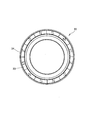
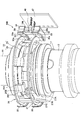
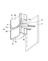
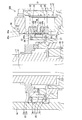
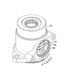
- FIG. 1 is a longitudinal sectional view of an electric power steering apparatus to which a torque sensor according to a first embodiment of the present invention is applied. It is the elements on larger scale of FIG. It is a bottom view of a magnetism generation part. It is a perspective view of the torque sensor which concerns on 1st Embodiment of this invention, and is a figure of the state which removed the housing. It is a perspective view of a rotating magnetic circuit part. It is a perspective view of a sensor holder. It is a perspective view of a magnetism collection yoke.
- the steering shaft 10 and the output shaft 12 rotate in conjunction with the steering wheel, and the wheels are moved by moving the rack shaft meshing with the pinion provided at the lower end of the output shaft 12 in the axial direction. To steer.
- the electric power steering apparatus 1 includes a worm wheel coupled to the output shaft 12, a worm meshing with the worm wheel, and an electric motor that rotationally drives the worm as an assist mechanism that assists in providing steering torque. Prepare.
- the electric power steering device 1 applies steering assist torque to the output shaft 12 by an electric motor.
- the steering shaft 10 includes an input shaft 11 as a first shaft and a torsion bar 21 connected to the input shaft 11.
- the input shaft 11 is rotatably supported by the housing 30 via a rolling bearing 37.
- the output shaft 12 as the second shaft is rotatably supported by the housing 49 via the rolling bearing 38.
- a sliding bearing 39 is interposed between the lower end side of the input shaft 11 and the upper end side of the output shaft 12.
- the input shaft 11 and the output shaft 12 are supported by the housings 30 and 49 so as to be rotatable on the same axis.
- the input shaft 11 is formed in a cylindrical shape, and a torsion bar 21 is accommodated coaxially inside the input shaft 11.
- the upper end portion of the torsion bar 21 is connected to the upper end portion of the input shaft 11 via a pin 28.
- a lower end portion of the torsion bar 21 protrudes from a lower end opening portion of the input shaft 11 and is connected to the output shaft 12 via a serration 29.
- the torsion bar 21 transmits the steering torque input to the input shaft 11 to the output shaft 12 via the steering wheel, and is torsionally deformed around the rotation axis O in accordance with the steering torque.
- the electric power steering apparatus 1 is provided with a non-contact type torque sensor 100 that detects a steering torque acting on a torsion bar 21 that connects the input shaft 11 and the output shaft 12.
- a non-contact type torque sensor 100 that detects a steering torque acting on a torsion bar 21 that connects the input shaft 11 and the output shaft 12.
- the torque sensor 100 includes a magnetic generator 22 that is fixed to the input shaft 11 and rotates with the input shaft 11, a rotating magnetic circuit unit 25 that is fixed to the output shaft 12 and rotates with the output shaft 12, and a fixed magnet that is fixed to the housing 30.
- the torque sensor 100 detects the steering torque acting on the torsion bar 21 based on the output of the magnetic sensor 48.
- the magnetism generating unit 22 may be fixed to the output shaft 12 so as to rotate with the output shaft 12, and the rotating magnetic circuit unit 25 may be fixed to the input shaft 11 so as to rotate with the input shaft 11. .
- the magnetism generator 22 includes an annular back yoke 24 that is press-fitted into the input shaft 11, and an annular ring magnet 23 that is coupled to the lower end surface of the back yoke 24.
- the ring magnet 23 is an annular permanent magnet that generates magnetism in the direction of the rotation axis O of the input shaft 11.
- the ring magnet 23 is a multipolar magnet formed by magnetizing a hard magnetic material in the direction of the rotation axis O, and has 12 magnetic poles formed with an equal width in the circumferential direction. That is, on the upper end surface and the lower end surface of the ring magnet 23, six N poles and six S poles are alternately arranged in the circumferential direction.
- the number of magnetic poles formed on the end face of the ring magnet 23 is arbitrarily set within a range of 2 or more.
- the upper magnetic pole surface which is the upper end surface of the ring magnet 23 is fixed to the lower end surface of the back yoke 24 via an adhesive. Further, since the back yoke 24 is formed of a soft magnetic material, it is magnetized by the magnetic field exerted by the ring magnet 23 and is attracted to the ring magnet 23. Thus, the ring magnet 23 and the back yoke 24 are coupled by the adhesive force and magnetic force of the adhesive.
- the back yoke 24 has a function as a connecting member for connecting the ring magnet 23 to the input shaft 11 and a function as a yoke for connecting the magnetic poles adjacent to the ring magnet 23 to guide the magnetic flux.
- the magnetic force is concentrated on the lower magnetic pole surface which is the end face.
- the rotating magnetic circuit unit 25 includes a first soft magnetic ring 26 and a second soft magnetism to which a magnetic flux generated from the ring magnet 23 of the magnetism generating unit 22 is guided.
- the first soft magnetic ring 26 includes an annular first magnetic path ring portion 26C, six first magnetic path column portions 26B protruding downward from the first magnetic path ring portion 26C, and each first magnetic path column portion.
- a first magnetic path front end portion 26A that refracts inward from the lower end of 26B and faces the lower end surface of the ring magnet 23.
- the second soft magnetic ring 27 includes an annular second magnetic path ring portion 27C, six second magnetic path column portions 27B protruding upward from the second magnetic path ring portion 27C, and each second magnetic path column portion.
- the second magnetic path tip portion 27A is refracted inward from the upper end of 27B and faces the lower end surface of the ring magnet 23.
- the first soft magnetic ring 26 and the second soft magnetic ring 27 are each formed by pressing.
- the first soft magnetic ring 26 and the second soft magnetic ring 27 are not limited to pressing, and may be formed by casting, sintering, or the like.
- the first magnetic path tip portion 26A and the second magnetic path tip portion 27A are formed in a flat plate shape.
- the first magnetic path tip end portion 26A and the second magnetic path tip end portion 27A are arranged on the same plane orthogonal to the rotation axis O of the torsion bar 21 alternately at equal intervals in the circumferential direction around the rotation axis O.
- first magnetic path tip portion 26A and the second magnetic path tip portion 27A are in a neutral state where no torque acts on the torsion bar 21, and the respective center lines extending in the radial direction of the torsion bar 21 are the ring magnets 23. It arrange
- the first magnetic path column portion 26B and the second magnetic path column portion 27B are each formed in a flat plate shape and extend in the direction of the rotation axis O.
- the first magnetic path column portion 26 ⁇ / b> B is disposed so as to surround the outer peripheral surface of the ring magnet 23 with a predetermined gap.
- the first magnetic path column part 26 ⁇ / b> B is provided so as not to short-circuit the magnetic flux of the ring magnet 23.
- the second magnetic path column portion 27B extends along the rotation axis O in the direction opposite to the first magnetic path column portion 26B.
- the first magnetic path ring portion 26C and the second magnetic path ring portion 27C are arranged on a plane orthogonal to the rotation axis O, and are formed in an annular shape with the entire circumference connected.
- the first magnetic path ring portion 26 ⁇ / b> C and the second magnetic path ring portion 27 ⁇ / b> C are not limited to this shape, and may be a C shape in which a slit is partially formed.
- the first magnetic path ring portion 26C is disposed above the lower end surface of the ring magnet 23, and the second magnetic path ring portion 27C is disposed below the ring magnet 23. That is, the ring magnet 23 is disposed between the first magnetic path ring portion 26C and the second magnetic path ring portion 27C in the rotation axis O direction.
- the fixed magnetic circuit portion 31 is provided along the outer periphery of the first magnetic path ring portion 26 ⁇ / b> C of the first soft magnetic ring 26.
- a magnetic yoke 34 and a second magnetic collecting yoke 35 connected to the second magnetic collecting ring 33 are provided.
- FIG. 4 a part of the first magnetism collecting ring 32 and the second magnetism collecting ring 33 is not shown.
- the first magnetism collecting ring 32 and the second magnetism collecting ring 33 have a C shape in which slits are partially formed, and are caulked and fixed to the inner peripheral surface of the housing 30.
- the inner peripheral surface of the first magnetic flux collecting ring 32 faces the first magnetic path ring portion 26C of the first soft magnetic ring 26, and the inner peripheral surface of the second magnetic flux collecting ring 33 is the second magnetic field of the second soft magnetic ring 27. It faces the road ring portion 27C.
- the first magnetism collecting ring 32 and the second magnetism collecting ring 33 are arranged on the outer periphery of the rotating magnetic circuit unit 25, and alleviate the influence of rotational shake and eccentricity of the rotating magnetic circuit unit 25, thereby reducing the magnetic sensor 48 side. Has the function of guiding the magnetic flux to the
- the first magnetic flux collecting yoke 34 is formed in a block shape having an arc-shaped inner circumferential surface 34 a that abuts the outer circumferential surface of the first magnetic flux collecting ring 32, and the second magnetic flux collecting yoke 35 is an outer circumferential surface of the second magnetic flux collecting ring 33. Is formed in a block shape having an arcuate inner peripheral surface 35a that abuts on the inner surface.
- the first magnetic flux collecting yoke 34 has a pair of magnetic flux collecting projections 34b extending in the direction of the rotational axis O
- the second magnetic flux collecting yoke 35 has a pair of magnetic flux collecting convex portions 35b extending in the direction of the rotational axis O.
- the pair of magnetic flux collecting convex portions 34b of the first magnetic flux collecting yoke 34 and the pair of magnetic flux collecting convex portions 35b of the second magnetic flux collecting yoke 35 face each other with a magnetic gap that is a predetermined gap. That is, a pair of magnetic gaps arranged in the circumferential direction is formed between the first magnetism collecting yoke 34 and the second magnetism collecting yoke 35.
- a magnetic sensor 48 is installed in each magnetic gap.
- the first magnetism collecting yoke 34 and the second magnetism collecting yoke 35 have a function of collecting the magnetic flux from the rotating magnetic circuit unit 25 to the magnetic sensor 48 via the first magnetism collecting ring 32 and the second magnetism collecting ring 33.
- the first magnetism collecting yoke 34, the second magnetism collecting yoke 35, the magnetic sensor 48, and the substrate 47 are fixed to the sensor holder 40 through a mold resin.
- the resin-made sensor holder 40 is attached to the metal housing 30 via a bolt inserted into the fastening hole 40b while the cylindrical portion 40a is fitted into the opening 30a of the housing 30.
- a Hall element is used for the magnetic sensor 48 for detecting magnetism.
- the hall element outputs a voltage corresponding to the magnetic flux density passing therethrough as a signal.
- the magnetic sensor 48 outputs a voltage corresponding to the magnitude and direction of the magnetic field of the magnetic gap through the substrate 47 and the terminal 44.
- the terminal 44 is connected to the controller via wiring connected to the sensor holder 40.
- the magnetic sensor 48 may include a circuit that amplifies a Hall element signal, a temperature compensation circuit, and a noise filter circuit.
- a pair of magnetic sensors 48 are provided corresponding to a pair of magnetic gaps arranged in the circumferential direction formed between the first magnetism collecting yoke 34 and the second magnetism collecting yoke 35, one being a main system and the other being a sub system.
- an output voltage output from the magnetic sensor 48 of the main system is used.
- the output voltage output from the magnetic sensor 48 of the sub system is used for diagnosing abnormality of the torque sensor 100 by the controller. Specifically, the controller compares the steering torque detected in the main system and the steering torque detected in the sub system, and determines that the difference is greater than or equal to a predetermined tolerance. It is determined that an abnormality has occurred in the torque sensor 100.
- the first magnetic path tip end portion 26 A of the first soft magnetic ring 26 and the second magnetic path tip end portion 27 A of the second soft magnetic ring 27 are respectively N of the ring magnet 23. Opposite the pole and the S pole with the same area and magnetically short-circuit both. Therefore, the magnetic flux is not guided to the rotating magnetic circuit unit 25 and the fixed magnetic circuit unit 31.
- the torsion bar 21 When a torque in a specific direction acts on the torsion bar 21 by the steering wheel operation by the driver, the torsion bar 21 is twisted and deformed according to the direction of the torque.
- the first magnetic path tip 26A faces the N pole with a larger area than the S pole, while the second magnetic path tip 27A has a larger area at the S pole than the N pole. Confront.
- the magnetic flux from the ring magnet 23 is guided to the fixed magnetic circuit unit 31 through the rotating magnetic circuit unit 25.
- the first soft magnetic ring 26, the first magnetic flux collecting ring 32, the first magnetic flux collecting yoke 34, the second magnetic flux collecting yoke 35, the second magnetic flux collecting ring 33, and the second soft magnetic ring 27 are arranged from the N pole. This is a route that goes to the south pole.
- the magnetic sensor 48 installed in the magnetic gap between the first magnetic collecting yoke 34 and the second magnetic collecting yoke 35 outputs a signal corresponding to the magnitude and direction of the magnetic flux.
- the torsion bar 21 when a torque in the opposite direction to the above acts on the torsion bar 21 by the operation of the steering wheel by the driver, the torsion bar 21 is twisted and deformed in the opposite direction according to the direction of the torque.
- the first magnetic path tip 26A opposes with a larger area than the N pole with the S pole, while the second magnetic path tip 27A has a larger area with the N pole than the S pole.
- the magnetic flux from the ring magnet 23 is guided to the fixed magnetic circuit unit 31 through the rotating magnetic circuit unit 25, but has a path opposite to the above.
- the second soft magnetic ring 27, the second magnetic flux collecting ring 33, the second magnetic flux collecting yoke 35, the first magnetic flux collecting yoke 34, the first magnetic flux collecting ring 32, and the first soft magnetic ring 26 are arranged from the N pole. This is a route that goes to the south pole.
- the magnetic sensor 48 installed in the magnetic gap between the first magnetic collecting yoke 34 and the second magnetic collecting yoke 35 outputs a signal corresponding to the magnitude and direction of the magnetic flux.
- the magnetic flux induced in the gap increases and the output signal of the magnetic sensor 48 also increases. Therefore, the magnetic flux density guided to the magnetic sensor 48 can be increased by increasing the number of magnetic poles of the ring magnet 23.
- the torsion bar 21 is torsionally deformed, and the first magnetic path tip 26A of the first soft magnetic ring 26 faces with a larger area from the S pole to the N pole, and the second soft magnetic ring 27
- a solid line arrow shows the path
- a dotted line arrow shows the path
- Leakage magnetic flux is guided from the first soft magnetic ring 26 to the second soft magnetic ring 27 by bypassing the magnetic sensor 48.
- the leakage magnetic flux path (indicated by the curved arrow in FIG. 23) that short-circuits the first soft magnetic ring 26 and the second soft magnetic ring 27 in the rotating magnetic circuit unit 25. Route) exists.
- the ring magnet 23 has six pairs of N poles and S poles, there are six magnetic flux paths that short-circuit the first soft magnetic ring 26 and the second soft magnetic ring 27.
- FIG. 9 is a graph showing the detection error of the torque sensor 100 due to the influence of the leakage magnetic flux.
- the horizontal axis in FIG. 9 is the rotation angle of the input shaft 11, and the vertical axis is the steering torque (detected torque) detected by the torque sensor 100.
- the solid line is the detected torque of the main system, and the dotted line is the detected torque of the sub system.
- FIG. 9 shows the detected torque of the torque sensor 100 when the input shaft 11 is rotated once so that the steering torque acting on the torsion bar 21 is constant. Since the steering torque acting on the torsion bar 21 is constant, the torque detected by the torque sensor 100 should be constant. However, the torque detected by the torque sensor 100 changes at a cycle of 60 ° as shown in FIG. This is because there are six paths of leakage flux that short-circuit the first soft magnetic ring 26 and the second soft magnetic ring 27 as described above, and the six leakage fluxes become lighter and darker as the input shaft 11 rotates. This is because it was detected. As described above, the torque sensor 100 also detects a change in leakage flux that depends on the rotation angle of the input shaft 11, that is, a change in leakage flux that is not related to the torsional deformation of the torsion bar 14.
- the magnetic sensor 48 detects a change (error component) in the leakage magnetic flux that is not related to the torsional deformation of the torsion bar 14, the magnetic sensor 48 twists the torsion bar 14 to the true magnetic flux density accompanying the torsional deformation of the torsion bar 14. Therefore, a magnetic flux density on which a change in leakage magnetic flux that is irrelevant is superimposed is detected, and a detection error occurs in the torque sensor 100.
- a detection error occurs in the torque sensor 100, an error occurs in the steering assist torque applied to the output shaft 12 by the electric motor. Therefore, when high-precision control is required by the electric power steering apparatus 1, it is necessary to prevent a detection error of the torque sensor 100 due to a change in leakage magnetic flux that is unrelated to the torsional deformation of the torsion bar 14.
- a shielding plate 50 for guiding the leakage flux and magnetically shielding the magnetic sensor 48 against the leakage flux is disposed.
- the shielding plate 50 has an arc shape having substantially the same radius of curvature as the inner peripheral surfaces 34a and 35a of the first magnetism collecting yoke 34 and the second magnetism collecting yoke 35, and is made of a magnetic material, specifically a soft magnetic material. Formed.
- the shielding plate 50 is integrally formed with the first magnetism collecting yoke 34 and the second magnetism collecting yoke 35 in the sensor holder 40 (see FIG. 6) via a molding resin. Specifically, the shielding plate 50 is fixed to a mold resin 51 (see FIG. 2) that is formed between the first magnetism collecting yoke 34 and the second magnetism collecting yoke 35 and supports both.
- the shielding plate 50 and the mold resin 51 are integrally molded by insert molding or outsert molding.
- the shielding plate 50 has a predetermined gap 52, 53 between the first magnetic flux collecting yoke 34 and the second magnetic flux collecting yoke 35 so that the inner circumferential surface 50a is flush with the inner circumferential surfaces 34a, 35a. It is arranged with a gap.
- the shielding plate 50 By arranging the shielding plate 50 between the first magnetism collecting yoke 34 and the second magnetism collecting yoke 35, leakage magnetic flux in the rotary magnetic circuit unit 25 is guided to the shielding plate 50 and does not reach the magnetic sensor 48. .
- the magnetic sensor 48 since the magnetic sensor 48 is magnetically shielded against the leakage magnetic flux in the rotating magnetic circuit unit 25 by the shielding plate 50, the change in the leakage magnetic flux not related to the torsional deformation of the torsion bar 14 is detected. Unaffected. Therefore, the detection error of the torque sensor 100 is eliminated, and the detection accuracy of the torque sensor 100 is increased.
- the gaps 52 and 53 are set to dimensions that can magnetically shield the magnetic sensor 48 against leakage magnetic flux in the rotating magnetic circuit unit 25 while suppressing a decrease in the detected magnetic flux density of the magnetic sensor 48. Is done.
- the leakage magnetic flux in the rotary magnetic circuit unit 25 is guided to the shielding plate 55 and is then transmitted from the first magnetism collecting yoke 34 to the first magnetism collecting yoke 34.
- the magnetic sensor 48 is guided to the second magnetic flux collecting yoke 35 or from the second magnetic flux collecting yoke 35 to the first magnetic flux collecting yoke 34.
- the shielding plate 50 by providing the shielding plate 50, the detection error of the torque sensor 100 due to the leakage magnetic flux in the rotating magnetic circuit unit 25 is eliminated, so that the magnetic sensor 48 can be disposed close to the input / output shafts 11 and 12. Thus, the torque sensor 100 can be reduced in size.
- the torque sensor 200 is different from the first embodiment in the configuration of the shielding plate 60 that induces a leakage flux between the first magnetism collecting yoke 34 and the second magnetism collecting yoke 35.
- the shielding plate 50 is formed separately from the first magnetism collecting yoke 34 and the second magnetism collecting yoke 35, but the shielding plate 60 in the torque sensor 200 is the first magnetism collecting yoke 34.
- the magnetic yoke 34 and the second magnetic flux collecting yoke 35 are integrally formed.
- the shielding plate 60 will be described in detail.
- Each of the first magnetism collecting yoke 34 and the second magnetism collecting yoke 35 has a first extension portion 34c and a second extension portion 35c formed by extending a part thereof.
- the first extension part 34c and the second extension part 35c are formed to extend toward each other, and are arranged to face each other with a predetermined gap 61 therebetween.
- the shielding plate 60 includes a first extension portion 34 c and a second extension portion 35 c that are arranged to face each other with a predetermined gap 61 therebetween, and is arranged between the rotating magnetic circuit unit 25 and the magnetic sensor 48.
- the shielding plate 60 has the same function as the shielding plate 50 in the first embodiment. That is, the shielding plate 60 induces a leakage flux between the first magnetism collecting yoke 34 and the second magnetism collecting yoke 35 and magnetically shields the magnetic sensor 48 against the leakage flux.
- the gap 61 between the first extension 34c and the second extension 35c prevents the leakage flux in the rotating magnetic circuit unit 25 while suppressing a decrease in the detected magnetic flux density of the magnetic sensor 48.
- the dimension is set such that the magnetic sensor 48 can be shielded magnetically.
- the shielding plate 55 formed integrally with the first magnetism collecting yoke 34 and the second magnetism collecting yoke 35 By providing the shielding plate 55 formed integrally with the first magnetism collecting yoke 34 and the second magnetism collecting yoke 35, the leakage magnetic flux in the rotary magnetic circuit section 25 is guided to the shielding plate 55, and the first magnetism collecting yoke.
- the magnetic sensor 48 is bypassed and guided from 34 to the second magnetic collecting yoke 35 or from the second magnetic collecting yoke 35 to the first magnetic collecting yoke 34.
- the magnetic sensor 48 since the leakage magnetic flux in the rotating magnetic circuit unit 25 does not reach the magnetic sensor 48, the magnetic sensor 48 is not affected by the change of the leakage magnetic flux that is not related to the torsional deformation of the torsion bar 14. Therefore, the detection error of the torque sensor 100 due to the leakage magnetic flux in the rotating magnetic circuit unit 25 is eliminated, and the detection accuracy of the torque sensor 100 is increased.
- the shielding plate 60 by providing the shielding plate 60, the detection error of the torque sensor 200 due to the leakage magnetic flux in the rotary magnetic circuit unit 25 is eliminated, so that the magnetic sensor 48 can be disposed close to the input / output shafts 11 and 12. Thus, the torque sensor 200 can be reduced in size.
- the shielding plate 60 includes a first extending portion 34c and a second extending portion 35c obtained by extending a part of the first and second magnetic collecting yokes 34 and 35, the shielding plate 50 is provided with the first collecting yoke.
- the torque sensor 100 according to the first embodiment provided separately from the 34 and the second magnetism collecting yoke 35 the number of parts can be reduced.
- a torque sensor 300 according to a third embodiment of the present invention will be described with reference to FIGS.
- the same components as those in the first embodiment will be denoted by the same reference numerals and description thereof will be omitted.
- a shielding plate 55 is disposed.
- the shielding plate 55 has an arc shape having substantially the same radius of curvature as the first magnetism collecting ring 32 and the second magnetism collecting ring 33, and has the same thickness as the first magnetism collecting ring 32 and the second magnetism collecting ring 33.
- the shielding plate 55 is made of a magnetic material, specifically, a soft magnetic material.
- the shielding plate 55 is integrally formed with the housing 30. Specifically, as shown in FIG. 6, the shielding plate 55 is fixed to a resin material 56 that is coupled to the inner peripheral surface of the opening 30a of the housing 30 and is formed so as to cross the opening 30a.
- the shielding plate 55 and the resin material 56 are integrally formed by insert molding or outsert molding. At both ends of the shielding plate 55, notches 55a into which pins for positioning the shielding plate 55 are fitted when the shielding plate 55 and the resin material 56 are integrally molded are formed.
- the shielding plate 55 may be integrally molded with the sensor holder 40. In that case, the shielding plate 55 is fixed to a mold resin 51 (see FIG. 2) that is formed between the first magnetism collecting yoke 34 and the second magnetism collecting yoke 35 and supports both.
- the shield plate 55 is disposed between the first magnetism collecting ring 32 and the second magnetism collecting ring 33 with predetermined gaps 57 and 58 therebetween.
- the shielding plate 55 By arranging the shielding plate 55 between the first magnetism collecting ring 32 and the second magnetism collecting ring 33, leakage magnetic flux in the rotating magnetic circuit unit 25 is guided to the shielding plate 55 and does not reach the magnetic sensor 48. .
- the magnetic sensor 48 is magnetically shielded against the leakage magnetic flux in the rotating magnetic circuit unit 25 by the shielding plate 55, the change in the leakage magnetic flux not related to the torsional deformation of the torsion bar 14 is caused. Unaffected. Therefore, the detection error of the torque sensor 300 is eliminated, and the detection accuracy of the torque sensor 300 is increased.
- the gaps 57 and 58 are set to dimensions capable of magnetically shielding the magnetic sensor 48 against leakage magnetic flux in the rotating magnetic circuit unit 25 while suppressing a decrease in the detected magnetic flux density of the magnetic sensor 48. Is done.
- the leakage magnetic flux in the rotary magnetic circuit unit 25 is guided to the shielding plate 55 and is then transmitted from the first magnetism collecting ring 32.
- the magnetic sensor 48 is guided to the second magnetism collecting ring 33 or from the second magnetism collecting ring 33 to the first magnetism collecting ring 32.
- the magnetic sensor 48 can be disposed close to the input / output shafts 11 and 12.
- the torque sensor 300 can be reduced in size.
- the torque sensor 400 is different from the third embodiment in the configuration of the shielding plate 65 that induces a leakage flux between the first magnetism collecting ring 32 and the second magnetism collecting ring 33.
- the shielding plate 55 is formed separately from the first magnetism collecting ring 32 and the second magnetism collecting ring 33, but the shielding plate 65 in the torque sensor 400 is the first magnetism collecting ring 32.
- the magnetic ring 32 and the second magnetic flux collecting ring 33 are integrally formed.
- the shielding plate 65 will be described in detail.
- Each of the first magnetism collecting ring 32 and the second magnetism collecting ring 33 has a first extension part 32a and a second extension part 33a formed by extending a part thereof.
- the first extension portion 32a and the second extension portion 33a are formed so as to extend toward each other, and are disposed to face each other with a predetermined gap 66 therebetween.
- the shielding plate 65 includes a first extension portion 32 a and a second extension portion 33 a that are arranged to face each other with a predetermined gap 66 therebetween, and is arranged between the rotating magnetic circuit portion 25 and the magnetic sensor 48.
- the shielding plate 65 has the same function as the shielding plate 55 in the first embodiment. That is, the shielding plate 65 induces a leakage flux between the first magnetism collecting ring 32 and the second magnetism collecting ring 33 and magnetically shields the magnetic sensor 48 against the leakage flux.
- the gap 66 between the first extension portion 32a and the second extension portion 33a suppresses a decrease in the detected magnetic flux density of the magnetic sensor 48, and prevents leakage magnetic flux in the rotating magnetic circuit portion 25.
- the dimension is set such that the magnetic sensor 48 can be shielded magnetically.
- the leakage flux in the rotary magnetic circuit unit 25 is induced to the shielding plate 55 and the first magnetism collecting ring.
- the magnetic sensor 48 is guided by bypassing the magnetic sensor 48 from the second magnetic flux collecting ring 33 to the second magnetic flux collecting ring 33 or from the second magnetic flux collecting ring 33 to the first magnetic flux collecting ring 32.
- the magnetic sensor 48 since the leakage magnetic flux in the rotating magnetic circuit unit 25 does not reach the magnetic sensor 48, the magnetic sensor 48 is not affected by the change of the leakage magnetic flux that is not related to the torsional deformation of the torsion bar 14. Therefore, the detection error of the torque sensor 400 due to the leakage magnetic flux in the rotating magnetic circuit unit 25 is eliminated, and the detection accuracy of the torque sensor 400 is increased.
- the shielding plate 65 by providing the shielding plate 65, the detection error of the torque sensor 400 caused by the leakage magnetic flux in the rotating magnetic circuit unit 25 is eliminated, so that the magnetic sensor 48 can be disposed close to the input / output shafts 11 and 12. Thus, the torque sensor 400 can be reduced in size.
- the shielding plate 65 includes a first extension portion 32a and a second extension portion 33a obtained by extending a part of the first magnetism collecting ring 32 and the second magnetism collecting ring 33, the shielding plate 55 serves as the first magnetism collecting ring. 32 and the second magnetism collecting ring 33, the number of parts can be reduced as compared with the torque sensor 300 according to the third embodiment provided separately.
- the present invention can be used as a torque sensor used in an electric power steering device that assists a steering force applied by a driver to a steering wheel.
Abstract
This torque sensor is provided with: a magnetism generating section, which rotates with a first shaft; a rotating magnetic circuit section, which rotates with a second shaft; a fixed magnetic circuit section, which is fixed to a housing; a magnetic detector, which detects the density of a magnetic flux that is led from the magnetism generating section to the fixed magnetic circuit section through the rotating magnetic circuit section due to torsional deformation of a torsion bar; and a shielding plate, which is disposed between the rotating magnetic circuit section and the magnetic detector, and which magnetically shields the magnetic detector.
Description
本発明は、トーションバーに作用するトルクを検出するトルクセンサに関するものである。
The present invention relates to a torque sensor that detects torque acting on a torsion bar.
車両のステアリング装置に設けられるトルクセンサとして、ステアリングシャフトに作用する操舵トルクを磁力によって検出する非接触タイプのものが知られている。
A non-contact type sensor that detects a steering torque acting on a steering shaft by a magnetic force is known as a torque sensor provided in a vehicle steering device.
JP2009-244205Aには、入力シャフトに固定される磁気発生部と、出力シャフトに固定される回転磁気回路部と、ハウジングに固定される固定磁気回路部と、固定磁気回路部に導かれる磁束密度を検出する磁気センサと、を備えるトルクセンサが開示されている。
JP2009-244205A includes a magnetic generator fixed to an input shaft, a rotating magnetic circuit fixed to an output shaft, a fixed magnetic circuit fixed to a housing, and a magnetic flux density guided to the fixed magnetic circuit. A torque sensor comprising a magnetic sensor for detection is disclosed.
入力シャフトと出力シャフトを連結するトーションバーにトルクが作用してトーションバーがねじれ変形すると、磁気発生部と回転磁気回路部との回転方向の相対位置が変化する。これに伴い磁気発生部から回転磁気回路部を通じて固定磁気回路部に導かれる磁束密度が変化する。磁気センサは磁束密度に応じた信号を出力する。トーションバーに作用するトルクは、磁気センサから出力された信号に基づいて検出される。
¡When torque acts on the torsion bar connecting the input shaft and the output shaft and the torsion bar is torsionally deformed, the relative position in the rotation direction of the magnetism generating unit and the rotating magnetic circuit unit changes. Along with this, the magnetic flux density guided from the magnetism generating unit to the fixed magnetic circuit unit through the rotating magnetic circuit unit changes. The magnetic sensor outputs a signal corresponding to the magnetic flux density. Torque acting on the torsion bar is detected based on a signal output from the magnetic sensor.
図23を参照して、トーションバーのねじれ変形に伴う磁束の経路について説明する。回転磁気回路部と固定磁気回路部の間における磁束の経路は、図23中直線の矢印にて示すように、磁気発生部の永久磁石91のN極から回転磁気回路部の第1軟磁性リング92、固定磁気回路部の第1集磁リング(図示省略)、第1集磁ヨーク93、第2集磁ヨーク94、第2集磁リング(図示省略)、回転磁気回路部の第2軟磁性リング95を経由して永久磁石91のS極に向かう経路である。磁気センサ96は、第1集磁ヨーク93と第2集磁ヨーク94の間に配置される。
Referring to FIG. 23, the path of magnetic flux accompanying torsional deformation of the torsion bar will be described. The path of the magnetic flux between the rotating magnetic circuit unit and the fixed magnetic circuit unit is shown by a straight arrow in FIG. 23 from the north pole of the permanent magnet 91 of the magnetism generating unit to the first soft magnetic ring of the rotating magnetic circuit unit. 92, a first magnetism collecting ring (not shown) of the fixed magnetic circuit section, a first magnetism collecting yoke 93, a second magnetism collecting yoke 94, a second magnetism collecting ring (not shown), and a second soft magnetism of the rotating magnetic circuit section. This is a path toward the south pole of the permanent magnet 91 via the ring 95. The magnetic sensor 96 is disposed between the first magnetism collecting yoke 93 and the second magnetism collecting yoke 94.
ここで、回転磁気回路部には、図23中曲線の矢印にて示すように、第1軟磁性リング92と第2軟磁性リング95の間に漏れ磁束が存在する。装置の小型化を目的として磁気センサ96を入出力シャフトに近づけると、磁気センサ96が回転磁気回路部の漏れ磁束に曝され、漏れ磁束の影響を受けてしまうため、トルクセンサに検出誤差が発生する。
Here, in the rotating magnetic circuit portion, as indicated by the curved arrow in FIG. 23, a leakage magnetic flux exists between the first soft magnetic ring 92 and the second soft magnetic ring 95. When the magnetic sensor 96 is brought close to the input / output shaft for the purpose of downsizing the device, the magnetic sensor 96 is exposed to the leakage magnetic flux of the rotating magnetic circuit section and is affected by the leakage magnetic flux, so that a detection error occurs in the torque sensor. To do.
本発明は、上記の問題点に鑑みてなされたものであり、トルクセンサの検出精度を高めることを目的とする。
The present invention has been made in view of the above problems, and an object thereof is to increase the detection accuracy of a torque sensor.
本発明のある態様によれば、ハウジング内に回転自在に支持された第1シャフトと第2シャフトとを連結するトーションバーに作用するトルクを検出するトルクセンサであって、前記第1シャフトと共に回転する磁気発生部と、前記第2シャフトと共に回転する回転磁気回路部と、前記ハウジングに固定された固定磁気回路部と、前記トーションバーのねじれ変形に伴って前記磁気発生部から前記回転磁気回路部を通じて前記固定磁気回路部に導かれる磁束密度を検出する磁気検出器と、前記回転磁気回路部と前記磁気検出器の間に配置され、前記磁気検出器を磁気的に遮蔽する遮蔽板と、を備えるトルクセンサが提供される。
According to an aspect of the present invention, there is provided a torque sensor that detects a torque acting on a torsion bar that connects a first shaft and a second shaft that are rotatably supported in a housing, and rotates with the first shaft. A rotating magnetic circuit unit rotating with the second shaft, a fixed magnetic circuit unit fixed to the housing, and the rotating magnetic circuit unit from the magnetic generating unit in accordance with torsional deformation of the torsion bar. A magnetic detector that detects a magnetic flux density guided to the fixed magnetic circuit unit through a shielding plate that is disposed between the rotating magnetic circuit unit and the magnetic detector and shields the magnetic detector magnetically. A torque sensor is provided.
図面を参照して、本発明の実施形態について説明する。
Embodiments of the present invention will be described with reference to the drawings.
<第1実施形態>
図1~図9を参照して、本発明の第1実施形態に係るトルクセンサ100について説明する。 <First Embodiment>
Atorque sensor 100 according to a first embodiment of the present invention will be described with reference to FIGS.
図1~図9を参照して、本発明の第1実施形態に係るトルクセンサ100について説明する。 <First Embodiment>
A
まず、図1を参照して、本発明の第1実施形態に係るトルクセンサ100が適用される電動パワーステアリング装置1について説明する。
First, an electric power steering device 1 to which a torque sensor 100 according to a first embodiment of the present invention is applied will be described with reference to FIG.
電動パワーステアリング装置1は、ステアリングシャフト10と出力シャフト12とがステアリングホイールに連係して回転し、出力シャフト12の下端に設けられたピニオンと噛合するラック軸を軸方向に移動させることで車輪を操舵するものである。
In the electric power steering apparatus 1, the steering shaft 10 and the output shaft 12 rotate in conjunction with the steering wheel, and the wheels are moved by moving the rack shaft meshing with the pinion provided at the lower end of the output shaft 12 in the axial direction. To steer.
また、電動パワーステアリング装置1は、操舵トルクを補助的に付与するアシスト機構として、出力シャフト12に連結されたウォームホイールと、ウォームホイールと噛合するウォームと、ウォームを回転駆動する電動モータと、を備える。電動パワーステアリング装置1は、電動モータによって出力シャフト12に操舵補助トルクを付与する。
The electric power steering apparatus 1 includes a worm wheel coupled to the output shaft 12, a worm meshing with the worm wheel, and an electric motor that rotationally drives the worm as an assist mechanism that assists in providing steering torque. Prepare. The electric power steering device 1 applies steering assist torque to the output shaft 12 by an electric motor.
ステアリングシャフト10は、第1シャフトとしての入力シャフト11と、入力シャフト11に連結されたトーションバー21と、から構成されている。入力シャフト11は、転がり軸受37を介してハウジング30に回転自在に支持される。第2シャフトとしての出力シャフト12は、転がり軸受38を介してハウジング49に回転自在に支持される。入力シャフト11の下端側と出力シャフト12の上端側との間には、滑り軸受39が介装される。入力シャフト11と出力シャフト12は、同一軸上で回転自在にハウジング30,49に支持される。
The steering shaft 10 includes an input shaft 11 as a first shaft and a torsion bar 21 connected to the input shaft 11. The input shaft 11 is rotatably supported by the housing 30 via a rolling bearing 37. The output shaft 12 as the second shaft is rotatably supported by the housing 49 via the rolling bearing 38. A sliding bearing 39 is interposed between the lower end side of the input shaft 11 and the upper end side of the output shaft 12. The input shaft 11 and the output shaft 12 are supported by the housings 30 and 49 so as to be rotatable on the same axis.
入力シャフト11は円筒状に形成されており、入力シャフト11の内部にはトーションバー21が同軸に収められる。トーションバー21の上端部は、ピン28を介して入力シャフト11の上端部に連結される。トーションバー21の下端部は、入力シャフト11の下端開口部より突出しており、セレーション29を介して出力シャフト12に連結される。トーションバー21は、ステアリングホイールを介して入力シャフト11に入力される操舵トルクを出力シャフト12に伝達し、その操舵トルクに応じて回転軸Oを中心にねじれ変形する。
The input shaft 11 is formed in a cylindrical shape, and a torsion bar 21 is accommodated coaxially inside the input shaft 11. The upper end portion of the torsion bar 21 is connected to the upper end portion of the input shaft 11 via a pin 28. A lower end portion of the torsion bar 21 protrudes from a lower end opening portion of the input shaft 11 and is connected to the output shaft 12 via a serration 29. The torsion bar 21 transmits the steering torque input to the input shaft 11 to the output shaft 12 via the steering wheel, and is torsionally deformed around the rotation axis O in accordance with the steering torque.
電動パワーステアリング装置1には、入力シャフト11と出力シャフト12とを連結するトーションバー21に作用する操舵トルクを検出する非接触式のトルクセンサ100が設けられる。以下では、トルクセンサ100について説明する。
The electric power steering apparatus 1 is provided with a non-contact type torque sensor 100 that detects a steering torque acting on a torsion bar 21 that connects the input shaft 11 and the output shaft 12. Hereinafter, the torque sensor 100 will be described.
トルクセンサ100は、入力シャフト11に固定され入力シャフト11と共に回転する磁気発生部22と、出力シャフト12に固定され出力シャフト12と共に回転する回転磁気回路部25と、ハウジング30に固定された固定磁気回路部31と、トーションバー21のねじれ変形に伴って磁気発生部22から回転磁気回路部25を通じて固定磁気回路部31に導かれる磁束密度を検出する磁気検出器としての磁気センサ48と、を備える。トルクセンサ100は、トーションバー21に作用する操舵トルクを磁気センサ48の出力に基づいて検出する。
The torque sensor 100 includes a magnetic generator 22 that is fixed to the input shaft 11 and rotates with the input shaft 11, a rotating magnetic circuit unit 25 that is fixed to the output shaft 12 and rotates with the output shaft 12, and a fixed magnet that is fixed to the housing 30. A circuit unit 31; and a magnetic sensor 48 as a magnetic detector that detects a magnetic flux density guided to the fixed magnetic circuit unit 31 from the magnetism generating unit 22 through the rotating magnetic circuit unit 25 in accordance with the torsional deformation of the torsion bar 21. . The torque sensor 100 detects the steering torque acting on the torsion bar 21 based on the output of the magnetic sensor 48.
上記構成に代え、磁気発生部22を出力シャフト12と共に回転するように出力シャフト12に固定し、回転磁気回路部25を入力シャフト11と共に回転するように入力シャフト11に固定するようにしてもよい。
Instead of the above configuration, the magnetism generating unit 22 may be fixed to the output shaft 12 so as to rotate with the output shaft 12, and the rotating magnetic circuit unit 25 may be fixed to the input shaft 11 so as to rotate with the input shaft 11. .
図1~図3に示すように、磁気発生部22は、入力シャフト11に圧入される環状のバックヨーク24と、バックヨーク24の下端面に結合される環状のリング磁石23と、を備える。
1 to 3, the magnetism generator 22 includes an annular back yoke 24 that is press-fitted into the input shaft 11, and an annular ring magnet 23 that is coupled to the lower end surface of the back yoke 24.
リング磁石23は、入力シャフト11の回転軸O方向に磁気を発生する環状の永久磁石である。リング磁石23は、回転軸O方向へ向けて硬磁性体を着磁することによって形成される多極磁石であり、周方向に等しい幅で形成される12個の磁極を有する。つまり、リング磁石23の上端面及び下端面には、6個のN極と6個のS極が周方向に交互に配設される。リング磁石23の端面に形成される磁極数は、2個以上の範囲で任意に設定される。
The ring magnet 23 is an annular permanent magnet that generates magnetism in the direction of the rotation axis O of the input shaft 11. The ring magnet 23 is a multipolar magnet formed by magnetizing a hard magnetic material in the direction of the rotation axis O, and has 12 magnetic poles formed with an equal width in the circumferential direction. That is, on the upper end surface and the lower end surface of the ring magnet 23, six N poles and six S poles are alternately arranged in the circumferential direction. The number of magnetic poles formed on the end face of the ring magnet 23 is arbitrarily set within a range of 2 or more.
バックヨーク24は、その下端面にリング磁石23の上端面である上部磁極面が接着剤を介して固定される。また、バックヨーク24は軟磁性体によって形成されるため、リング磁石23が及ぼす磁界によって磁化され、リング磁石23に吸着する。このように、リング磁石23とバックヨーク24は、接着剤の接着力と磁力とによって結合される。バックヨーク24は、リング磁石23を入力シャフト11に連結する連結部材としての機能と、リング磁石23の隣り合う磁極を結んで磁束を導く継鉄としての機能とを有し、リング磁石23の下端面である下部磁極面に磁力を集中させる。
The upper magnetic pole surface which is the upper end surface of the ring magnet 23 is fixed to the lower end surface of the back yoke 24 via an adhesive. Further, since the back yoke 24 is formed of a soft magnetic material, it is magnetized by the magnetic field exerted by the ring magnet 23 and is attracted to the ring magnet 23. Thus, the ring magnet 23 and the back yoke 24 are coupled by the adhesive force and magnetic force of the adhesive. The back yoke 24 has a function as a connecting member for connecting the ring magnet 23 to the input shaft 11 and a function as a yoke for connecting the magnetic poles adjacent to the ring magnet 23 to guide the magnetic flux. The magnetic force is concentrated on the lower magnetic pole surface which is the end face.
図1,図2,図4,及び図5に示すように、回転磁気回路部25は、磁気発生部22のリング磁石23から発生する磁束が導かれる第1軟磁性リング26及び第2軟磁性リング27と、出力シャフト12に取り付けられる取付部材70と、取付部材70に第1軟磁性リング26及び第2軟磁性リング27を固定するモールド樹脂71と、を備える。
As shown in FIGS. 1, 2, 4, and 5, the rotating magnetic circuit unit 25 includes a first soft magnetic ring 26 and a second soft magnetism to which a magnetic flux generated from the ring magnet 23 of the magnetism generating unit 22 is guided. A ring 27, an attachment member 70 attached to the output shaft 12, and a mold resin 71 that fixes the first soft magnetic ring 26 and the second soft magnetic ring 27 to the attachment member 70.
第1軟磁性リング26は、環状の第1磁路環部26Cと、第1磁路環部26Cから下向きに突出する6個の第1磁路柱部26Bと、各第1磁路柱部26Bの下端からそれぞれ内向きに屈折してリング磁石23の下端面に対峙する第1磁路先端部26Aと、からなる。第2軟磁性リング27は、環状の第2磁路環部27Cと、第2磁路環部27Cから上向きに突出する6個の第2磁路柱部27Bと、各第2磁路柱部27Bの上端からそれぞれ内向きに屈折してリング磁石23の下端面に対峙する第2磁路先端部27Aと、からなる。
The first soft magnetic ring 26 includes an annular first magnetic path ring portion 26C, six first magnetic path column portions 26B protruding downward from the first magnetic path ring portion 26C, and each first magnetic path column portion. A first magnetic path front end portion 26A that refracts inward from the lower end of 26B and faces the lower end surface of the ring magnet 23. The second soft magnetic ring 27 includes an annular second magnetic path ring portion 27C, six second magnetic path column portions 27B protruding upward from the second magnetic path ring portion 27C, and each second magnetic path column portion. The second magnetic path tip portion 27A is refracted inward from the upper end of 27B and faces the lower end surface of the ring magnet 23.
第1軟磁性リング26及び第2軟磁性リング27は、それぞれプレス加工によって形成される。第1軟磁性リング26及び第2軟磁性リング27は、プレス加工に限らず、鋳造、焼結等によって形成してもよい。
The first soft magnetic ring 26 and the second soft magnetic ring 27 are each formed by pressing. The first soft magnetic ring 26 and the second soft magnetic ring 27 are not limited to pressing, and may be formed by casting, sintering, or the like.
第1磁路先端部26A及び第2磁路先端部27Aは平板状に形成される。第1磁路先端部26Aと第2磁路先端部27Aは、トーションバー21の回転軸Oと直交する同一平面上に、回転軸Oを中心として周方向に交互に等間隔を空けて配置される。
The first magnetic path tip portion 26A and the second magnetic path tip portion 27A are formed in a flat plate shape. The first magnetic path tip end portion 26A and the second magnetic path tip end portion 27A are arranged on the same plane orthogonal to the rotation axis O of the torsion bar 21 alternately at equal intervals in the circumferential direction around the rotation axis O. The
また、第1磁路先端部26Aと第2磁路先端部27Aは、トーションバー21にトルクが作用していない中立状態で、トーションバー21の径方向に延びるそれぞれの中心線がリング磁石23のN極とS極の境界を指すように配置される。
Further, the first magnetic path tip portion 26A and the second magnetic path tip portion 27A are in a neutral state where no torque acts on the torsion bar 21, and the respective center lines extending in the radial direction of the torsion bar 21 are the ring magnets 23. It arrange | positions so that the boundary of N pole and S pole may be pointed out.
第1磁路柱部26Bと第2磁路柱部27Bは、それぞれ平板状に形成され、回転軸O方向に延設される。第1磁路柱部26Bは、所定の間隙を空けてリング磁石23の外周面を囲むように配置される。第1磁路柱部26Bは、リング磁石23の磁束を短絡しないように設けられる。また、第2磁路柱部27Bは、回転軸Oに沿って第1磁路柱部26Bと反対方向に延設される。
The first magnetic path column portion 26B and the second magnetic path column portion 27B are each formed in a flat plate shape and extend in the direction of the rotation axis O. The first magnetic path column portion 26 </ b> B is disposed so as to surround the outer peripheral surface of the ring magnet 23 with a predetermined gap. The first magnetic path column part 26 </ b> B is provided so as not to short-circuit the magnetic flux of the ring magnet 23. The second magnetic path column portion 27B extends along the rotation axis O in the direction opposite to the first magnetic path column portion 26B.
第1磁路環部26C及び第2磁路環部27Cは、回転軸Oと直交する平面上に配置され、全周がつながった環状に形成される。第1磁路環部26C及び第2磁路環部27Cは、この形状に限られず、部分的にスリットが形成されたC字形状であってもよい。
The first magnetic path ring portion 26C and the second magnetic path ring portion 27C are arranged on a plane orthogonal to the rotation axis O, and are formed in an annular shape with the entire circumference connected. The first magnetic path ring portion 26 </ b> C and the second magnetic path ring portion 27 </ b> C are not limited to this shape, and may be a C shape in which a slit is partially formed.
第1磁路環部26Cはリング磁石23の下端面より上方に配置され、第2磁路環部27Cはリング磁石23より下方に配置される。つまり、リング磁石23は、回転軸O方向について第1磁路環部26Cと第2磁路環部27Cの間に配置される。
The first magnetic path ring portion 26C is disposed above the lower end surface of the ring magnet 23, and the second magnetic path ring portion 27C is disposed below the ring magnet 23. That is, the ring magnet 23 is disposed between the first magnetic path ring portion 26C and the second magnetic path ring portion 27C in the rotation axis O direction.
図1,図2,図4,図6,及び図7に示すように、固定磁気回路部31は、第1軟磁性リング26の第1磁路環部26Cの外周に沿って設けられた第1集磁リング32と、第2軟磁性リング27の第2磁路環部27Cの外周に沿って設けられた第2集磁リング33と、第1集磁リング32に接続された第1集磁ヨーク34と、第2集磁リング33に接続された第2集磁ヨーク35と、を備える。なお、図4では、第1集磁リング32及び第2集磁リング33の一部の図示を省略している。
As shown in FIGS. 1, 2, 4, 6, and 7, the fixed magnetic circuit portion 31 is provided along the outer periphery of the first magnetic path ring portion 26 </ b> C of the first soft magnetic ring 26. A first magnetic flux collecting ring 32, a second magnetic flux collecting ring 33 provided along the outer periphery of the second magnetic path ring portion 27 </ b> C of the second soft magnetic ring 27, and a first magnetic flux collecting ring 32 connected to the first magnetic flux collecting ring 32. A magnetic yoke 34 and a second magnetic collecting yoke 35 connected to the second magnetic collecting ring 33 are provided. In FIG. 4, a part of the first magnetism collecting ring 32 and the second magnetism collecting ring 33 is not shown.
第1集磁リング32及び第2集磁リング33は、部分的にスリットが形成されたC字形状であり、ハウジング30の内周面にかしめ固定される。第1集磁リング32の内周面は第1軟磁性リング26の第1磁路環部26Cに対峙し、第2集磁リング33の内周面は第2軟磁性リング27の第2磁路環部27Cに対峙する。
The first magnetism collecting ring 32 and the second magnetism collecting ring 33 have a C shape in which slits are partially formed, and are caulked and fixed to the inner peripheral surface of the housing 30. The inner peripheral surface of the first magnetic flux collecting ring 32 faces the first magnetic path ring portion 26C of the first soft magnetic ring 26, and the inner peripheral surface of the second magnetic flux collecting ring 33 is the second magnetic field of the second soft magnetic ring 27. It faces the road ring portion 27C.
このように、第1集磁リング32及び第2集磁リング33は、回転磁気回路部25の外周に配置され、回転磁気回路部25の回転振れや偏心の影響を緩和して磁気センサ48側へ磁束を導く機能を有する。
As described above, the first magnetism collecting ring 32 and the second magnetism collecting ring 33 are arranged on the outer periphery of the rotating magnetic circuit unit 25, and alleviate the influence of rotational shake and eccentricity of the rotating magnetic circuit unit 25, thereby reducing the magnetic sensor 48 side. Has the function of guiding the magnetic flux to the
第1集磁ヨーク34は第1集磁リング32の外周面に当接する円弧状の内周面34aを有するブロック状に形成され、第2集磁ヨーク35は第2集磁リング33の外周面に当接する円弧状の内周面35aを有するブロック形状に形成される。
The first magnetic flux collecting yoke 34 is formed in a block shape having an arc-shaped inner circumferential surface 34 a that abuts the outer circumferential surface of the first magnetic flux collecting ring 32, and the second magnetic flux collecting yoke 35 is an outer circumferential surface of the second magnetic flux collecting ring 33. Is formed in a block shape having an arcuate inner peripheral surface 35a that abuts on the inner surface.
第1集磁ヨーク34には一対の集磁凸部34bが回転軸O方向に延設され、第2集磁ヨーク35にも一対の集磁凸部35bが回転軸O方向に延設される。第1集磁ヨーク34の一対の集磁凸部34bと第2集磁ヨーク35の一対の集磁凸部35bは、所定の隙間である磁気ギャップをもって互いに対向する。つまり、第1集磁ヨーク34と第2集磁ヨーク35との間には、周方向に並ぶ一対の磁気ギャップが形成される。それぞれの磁気ギャップ内には磁気センサ48が設置される。
The first magnetic flux collecting yoke 34 has a pair of magnetic flux collecting projections 34b extending in the direction of the rotational axis O, and the second magnetic flux collecting yoke 35 has a pair of magnetic flux collecting convex portions 35b extending in the direction of the rotational axis O. . The pair of magnetic flux collecting convex portions 34b of the first magnetic flux collecting yoke 34 and the pair of magnetic flux collecting convex portions 35b of the second magnetic flux collecting yoke 35 face each other with a magnetic gap that is a predetermined gap. That is, a pair of magnetic gaps arranged in the circumferential direction is formed between the first magnetism collecting yoke 34 and the second magnetism collecting yoke 35. A magnetic sensor 48 is installed in each magnetic gap.
第1集磁ヨーク34及び第2集磁ヨーク35は、回転磁気回路部25からの磁束を第1集磁リング32及び第2集磁リング33を介して磁気センサ48へ集める機能を有する。
The first magnetism collecting yoke 34 and the second magnetism collecting yoke 35 have a function of collecting the magnetic flux from the rotating magnetic circuit unit 25 to the magnetic sensor 48 via the first magnetism collecting ring 32 and the second magnetism collecting ring 33.
第1集磁ヨーク34、第2集磁ヨーク35、磁気センサ48、及び基板47は、モールド樹脂を介してセンサホルダ40に固定される。樹脂製のセンサホルダ40は、円筒部40aがハウジング30の開口部30aに嵌挿されると共に、締結穴40bに挿入されるボルトを介して金属製のハウジング30に取り付けられる。
The first magnetism collecting yoke 34, the second magnetism collecting yoke 35, the magnetic sensor 48, and the substrate 47 are fixed to the sensor holder 40 through a mold resin. The resin-made sensor holder 40 is attached to the metal housing 30 via a bolt inserted into the fastening hole 40b while the cylindrical portion 40a is fitted into the opening 30a of the housing 30.
磁気を検出するための磁気センサ48にはホール素子が用いられる。ホール素子は、これを通過する磁束密度に応じた電圧を信号として出力するものである。磁気センサ48は、磁気ギャップの磁場の大きさ及び方向に応じた電圧を、基板47及び端子44を通じて出力する。端子44は、センサホルダ40に接続される配線を介してコントローラに接続される。磁気センサ48には、ホール素子の信号を増幅する回路、温度補償を行う回路、及びノイズフィルタの回路等を備えるものを用いてもよい。
A Hall element is used for the magnetic sensor 48 for detecting magnetism. The hall element outputs a voltage corresponding to the magnetic flux density passing therethrough as a signal. The magnetic sensor 48 outputs a voltage corresponding to the magnitude and direction of the magnetic field of the magnetic gap through the substrate 47 and the terminal 44. The terminal 44 is connected to the controller via wiring connected to the sensor holder 40. The magnetic sensor 48 may include a circuit that amplifies a Hall element signal, a temperature compensation circuit, and a noise filter circuit.
磁気センサ48は、第1集磁ヨーク34と第2集磁ヨーク35の間に形成された周方向に並ぶ一対の磁気ギャップに対応して一対設けられ、一方がメイン系統、他方がサブ系統となる。電動パワーステアリング装置1の電動モータの制御には、メイン系統の磁気センサ48から出力される出力電圧が用いられる。サブ系統の磁気センサ48から出力される出力電圧は、コントローラにてトルクセンサ100の異常を診断するために用いられる。具体的には、コントローラは、メイン系統にて検出された操舵トルクとサブ系統にて検出された操舵トルクとを比較し、その差が予め定められた許容差以上であると判断した場合には、トルクセンサ100に異常が発生していると判定する。
A pair of magnetic sensors 48 are provided corresponding to a pair of magnetic gaps arranged in the circumferential direction formed between the first magnetism collecting yoke 34 and the second magnetism collecting yoke 35, one being a main system and the other being a sub system. Become. For control of the electric motor of the electric power steering apparatus 1, an output voltage output from the magnetic sensor 48 of the main system is used. The output voltage output from the magnetic sensor 48 of the sub system is used for diagnosing abnormality of the torque sensor 100 by the controller. Specifically, the controller compares the steering torque detected in the main system and the steering torque detected in the sub system, and determines that the difference is greater than or equal to a predetermined tolerance. It is determined that an abnormality has occurred in the torque sensor 100.
次に、トルクセンサ100によるトーションバー21に作用する操舵トルクの検出方法について説明する。
Next, a method for detecting the steering torque acting on the torsion bar 21 by the torque sensor 100 will be described.
トーションバー21にトルクが作用しない中立状態では、第1軟磁性リング26の第1磁路先端部26Aと第2軟磁性リング27の第2磁路先端部27Aとは、それぞれリング磁石23のN極及びS極に同一の面積で対峙して両者を磁気短絡する。そのため、磁束は回転磁気回路部25と固定磁気回路部31に導かれない。
In a neutral state in which no torque acts on the torsion bar 21, the first magnetic path tip end portion 26 A of the first soft magnetic ring 26 and the second magnetic path tip end portion 27 A of the second soft magnetic ring 27 are respectively N of the ring magnet 23. Opposite the pole and the S pole with the same area and magnetically short-circuit both. Therefore, the magnetic flux is not guided to the rotating magnetic circuit unit 25 and the fixed magnetic circuit unit 31.
運転者によるステアリングホイールの操作によってトーションバー21に特定の方向のトルクが作用した場合には、このトルクの方向に応じてトーションバー21はねじれ変形する。トーションバー21がねじれ変形すると、第1磁路先端部26AがS極よりN極に大きな面積を持って対峙する一方、第2磁路先端部27AがN極よりS極に大きな面積を持って対峙する。リング磁石23からの磁束は回転磁気回路部25を通じて固定磁気回路部31に導かれる。具体的には、N極から第1軟磁性リング26、第1集磁リング32、第1集磁ヨーク34、第2集磁ヨーク35、第2集磁リング33、第2軟磁性リング27を経由してS極に向かう経路である。第1集磁ヨーク34と第2集磁ヨーク35の間の磁気ギャップに設置された磁気センサ48は、磁束の大きさ及び方向に応じた信号を出力する。
When a torque in a specific direction acts on the torsion bar 21 by the steering wheel operation by the driver, the torsion bar 21 is twisted and deformed according to the direction of the torque. When the torsion bar 21 is torsionally deformed, the first magnetic path tip 26A faces the N pole with a larger area than the S pole, while the second magnetic path tip 27A has a larger area at the S pole than the N pole. Confront. The magnetic flux from the ring magnet 23 is guided to the fixed magnetic circuit unit 31 through the rotating magnetic circuit unit 25. Specifically, the first soft magnetic ring 26, the first magnetic flux collecting ring 32, the first magnetic flux collecting yoke 34, the second magnetic flux collecting yoke 35, the second magnetic flux collecting ring 33, and the second soft magnetic ring 27 are arranged from the N pole. This is a route that goes to the south pole. The magnetic sensor 48 installed in the magnetic gap between the first magnetic collecting yoke 34 and the second magnetic collecting yoke 35 outputs a signal corresponding to the magnitude and direction of the magnetic flux.
一方、運転者によるステアリングホイールの操作によってトーションバー21に上記とは逆方向のトルクが作用した場合には、このトルクの方向に応じてトーションバー21が逆方向にねじれ変形する。トーションバー21がねじれ変形すると、第1磁路先端部26AがN極よりS極に大きな面積を持って対峙する一方、第2磁路先端部27AがS極よりN極に大きな面積を持って対峙する。リング磁石23からの磁束は、回転磁気回路部25を通じて固定磁気回路部31に導かれるが、上記とは逆の経路となる。具体的には、N極から第2軟磁性リング27、第2集磁リング33、第2集磁ヨーク35、第1集磁ヨーク34、第1集磁リング32、第1軟磁性リング26を経由してS極に向かう経路である。第1集磁ヨーク34と第2集磁ヨーク35の間の磁気ギャップに設置された磁気センサ48は、磁束の大きさ及び方向に応じた信号を出力する。
On the other hand, when a torque in the opposite direction to the above acts on the torsion bar 21 by the operation of the steering wheel by the driver, the torsion bar 21 is twisted and deformed in the opposite direction according to the direction of the torque. When the torsion bar 21 is torsionally deformed, the first magnetic path tip 26A opposes with a larger area than the N pole with the S pole, while the second magnetic path tip 27A has a larger area with the N pole than the S pole. Confront. The magnetic flux from the ring magnet 23 is guided to the fixed magnetic circuit unit 31 through the rotating magnetic circuit unit 25, but has a path opposite to the above. Specifically, the second soft magnetic ring 27, the second magnetic flux collecting ring 33, the second magnetic flux collecting yoke 35, the first magnetic flux collecting yoke 34, the first magnetic flux collecting ring 32, and the first soft magnetic ring 26 are arranged from the N pole. This is a route that goes to the south pole. The magnetic sensor 48 installed in the magnetic gap between the first magnetic collecting yoke 34 and the second magnetic collecting yoke 35 outputs a signal corresponding to the magnitude and direction of the magnetic flux.
第1磁路先端部26Aがリング磁石23のN極とS極に対峙する面積差、及び第2磁路先端部27Aがリング磁石23のN極とS極に対峙する面積差が大きいほど磁気ギャップに誘導される磁束が大きくなり、磁気センサ48の出力信号も増大する。したがって、リング磁石23の磁極数を増やすことにより、磁気センサ48に導かれる磁束密度を高めることができる。
The larger the difference in the area where the first magnetic path tip 26A faces the N and S poles of the ring magnet 23 and the larger the area difference where the second magnetic path tip 27A faces the N and S poles of the ring magnet 23, the greater the magnetism. The magnetic flux induced in the gap increases and the output signal of the magnetic sensor 48 also increases. Therefore, the magnetic flux density guided to the magnetic sensor 48 can be increased by increasing the number of magnetic poles of the ring magnet 23.
ここで、図8,図9,及び図23を参照して、回転磁気回路部25内の漏れ磁束について説明する。
Here, with reference to FIG. 8, FIG. 9, and FIG. 23, the leakage magnetic flux in the rotating magnetic circuit unit 25 will be described.
図8は、トーションバー21がねじれ変形して、第1軟磁性リング26の第1磁路先端部26AがS極よりN極に大きな面積を持って対峙し、第2軟磁性リング27の第2磁路先端部27AがN極よりS極に大きな面積を持って対峙した場合の磁束の経路を示す図であり、実線矢印が正規の磁束の経路を示し、点線矢印が漏れ磁束の経路を示す。
In FIG. 8, the torsion bar 21 is torsionally deformed, and the first magnetic path tip 26A of the first soft magnetic ring 26 faces with a larger area from the S pole to the N pole, and the second soft magnetic ring 27 It is a figure which shows the path | route of a magnetic flux when 2A magnetic path front-end | tip part 27A opposes with a larger area from a north pole to a south pole, a solid line arrow shows the path | route of a normal magnetic flux, and a dotted line arrow shows the path | route of a leakage flux Show.
漏れ磁束は、第1軟磁性リング26から磁気センサ48をバイパスして第2軟磁性リング27へ導かれる。このように、正規の磁束の経路とは別に、回転磁気回路部25内に、第1軟磁性リング26と第2軟磁性リング27を短絡する漏れ磁束の経路(図23中曲線の矢印で示す経路)が存在する。漏れ磁束の経路は、リング磁石23のN極から第1軟磁性リング26及び第2軟磁性リング27を通じてS極に向かうため、磁極の数の分だけ存在する。本実施形態では、リング磁石23はN極とS極を6対有するため、第1軟磁性リング26と第2軟磁性リング27を短絡する磁束の経路は6つ存在することになる。
Leakage magnetic flux is guided from the first soft magnetic ring 26 to the second soft magnetic ring 27 by bypassing the magnetic sensor 48. Thus, apart from the normal magnetic flux path, the leakage magnetic flux path (indicated by the curved arrow in FIG. 23) that short-circuits the first soft magnetic ring 26 and the second soft magnetic ring 27 in the rotating magnetic circuit unit 25. Route) exists. There are as many leakage flux paths as there are magnetic poles because the magnetic flux passes from the north pole of the ring magnet 23 to the south pole through the first soft magnetic ring 26 and the second soft magnetic ring 27. In the present embodiment, since the ring magnet 23 has six pairs of N poles and S poles, there are six magnetic flux paths that short-circuit the first soft magnetic ring 26 and the second soft magnetic ring 27.
図9は、漏れ磁束の影響によるトルクセンサ100の検出誤差を示すグラフ図である。図9の横軸は入力シャフト11の回転角度であり、縦軸はトルクセンサ100が検出した操舵トルク(検出トルク)である。また、図9中実線はメイン系統の検出トルクであり、点線はサブ系統の検出トルクである。
FIG. 9 is a graph showing the detection error of the torque sensor 100 due to the influence of the leakage magnetic flux. The horizontal axis in FIG. 9 is the rotation angle of the input shaft 11, and the vertical axis is the steering torque (detected torque) detected by the torque sensor 100. In FIG. 9, the solid line is the detected torque of the main system, and the dotted line is the detected torque of the sub system.
図9は、トーションバー21に作用する操舵トルクが一定となるように入力シャフト11を1回転させた場合のトルクセンサ100の検出トルクを示すものである。トーションバー21に作用する操舵トルクが一定であるため、本来ならトルクセンサ100の検出トルクは一定でなければならない。しかし、トルクセンサ100の検出トルクは、図9に示すように、60°周期で変化している。これは、第1軟磁性リング26と第2軟磁性リング27を短絡する漏れ磁束の経路が上述のように6つ存在し、その6つの漏れ磁束が入力シャフト11の回転に伴って濃淡となって検出されたためである。このように、トルクセンサ100は、入力シャフト11の回転角度に依存する漏れ磁束の変化、つまりトーションバー14のねじれ変形とは関係のない漏れ磁束の変化も検出してしまう。
FIG. 9 shows the detected torque of the torque sensor 100 when the input shaft 11 is rotated once so that the steering torque acting on the torsion bar 21 is constant. Since the steering torque acting on the torsion bar 21 is constant, the torque detected by the torque sensor 100 should be constant. However, the torque detected by the torque sensor 100 changes at a cycle of 60 ° as shown in FIG. This is because there are six paths of leakage flux that short-circuit the first soft magnetic ring 26 and the second soft magnetic ring 27 as described above, and the six leakage fluxes become lighter and darker as the input shaft 11 rotates. This is because it was detected. As described above, the torque sensor 100 also detects a change in leakage flux that depends on the rotation angle of the input shaft 11, that is, a change in leakage flux that is not related to the torsional deformation of the torsion bar 14.
磁気センサ48がトーションバー14のねじれ変形とは関係のない漏れ磁束の変化(誤差成分)を捉えると、磁気センサ48はトーションバー14のねじれ変形に伴う真の磁束密度にトーションバー14のねじれ変形とは関係のない漏れ磁束の変化が重畳された磁束密度を検出することになり、トルクセンサ100に検出誤差が発生する。トルクセンサ100に検出誤差が発生すると、電動モータによって出力シャフト12に付与される操舵補助トルクに誤差が生じてしまう。したがって、電動パワーステアリング装置1により精度の高い制御が求められる場合には、トーションバー14のねじれ変形とは関係のない漏れ磁束の変化によるトルクセンサ100の検出誤差は防止する必要がある。
When the magnetic sensor 48 detects a change (error component) in the leakage magnetic flux that is not related to the torsional deformation of the torsion bar 14, the magnetic sensor 48 twists the torsion bar 14 to the true magnetic flux density accompanying the torsional deformation of the torsion bar 14. Therefore, a magnetic flux density on which a change in leakage magnetic flux that is irrelevant is superimposed is detected, and a detection error occurs in the torque sensor 100. When a detection error occurs in the torque sensor 100, an error occurs in the steering assist torque applied to the output shaft 12 by the electric motor. Therefore, when high-precision control is required by the electric power steering apparatus 1, it is necessary to prevent a detection error of the torque sensor 100 due to a change in leakage magnetic flux that is unrelated to the torsional deformation of the torsion bar 14.
その対策として、図2,図4,図6,及び図7に示すように、回転磁気回路部25と磁気センサ48の間には、第1集磁ヨーク34と第2集磁ヨーク35の間で漏れ磁束を誘導し、漏れ磁束に対して磁気センサ48を磁気的に遮蔽する遮蔽板50が配置される。
As countermeasures, as shown in FIGS. 2, 4, 6, and 7, between the rotating magnetic circuit unit 25 and the magnetic sensor 48, between the first magnetic collecting yoke 34 and the second magnetic collecting yoke 35. A shielding plate 50 for guiding the leakage flux and magnetically shielding the magnetic sensor 48 against the leakage flux is disposed.
遮蔽板50は、第1集磁ヨーク34及び第2集磁ヨーク35の内周面34a,35aと略同一の曲率半径を有する円弧形状であり、磁材材料、具体的には軟磁性体にて形成される。
The shielding plate 50 has an arc shape having substantially the same radius of curvature as the inner peripheral surfaces 34a and 35a of the first magnetism collecting yoke 34 and the second magnetism collecting yoke 35, and is made of a magnetic material, specifically a soft magnetic material. Formed.
遮蔽板50は、第1集磁ヨーク34及び第2集磁ヨーク35と共にモールド樹脂を介してセンサホルダ40(図6参照)に一体成型される。具体的には、遮蔽板50は、第1集磁ヨーク34及び第2集磁ヨーク35の間に形成され両者を支持するモールド樹脂51(図2参照)に固定される。遮蔽板50とモールド樹脂51は、インサート成型又はアウトサート成形によって一体成型される。
The shielding plate 50 is integrally formed with the first magnetism collecting yoke 34 and the second magnetism collecting yoke 35 in the sensor holder 40 (see FIG. 6) via a molding resin. Specifically, the shielding plate 50 is fixed to a mold resin 51 (see FIG. 2) that is formed between the first magnetism collecting yoke 34 and the second magnetism collecting yoke 35 and supports both. The shielding plate 50 and the mold resin 51 are integrally molded by insert molding or outsert molding.
遮蔽板50は、内周面50aが内周面34a,35aと同一面上となるように、かつ第1集磁ヨーク34と第2集磁ヨーク35の間に両者と所定の隙間52,53を空けて配置される。
The shielding plate 50 has a predetermined gap 52, 53 between the first magnetic flux collecting yoke 34 and the second magnetic flux collecting yoke 35 so that the inner circumferential surface 50a is flush with the inner circumferential surfaces 34a, 35a. It is arranged with a gap.
第1集磁ヨーク34と第2集磁ヨーク35の間に遮蔽板50を配置することによって、回転磁気回路部25内での漏れ磁束が遮蔽板50に誘導されて磁気センサ48に到達しなくなる。このように、磁気センサ48は、遮蔽板50によって回転磁気回路部25内での漏れ磁束に対して磁気的に遮蔽されるため、トーションバー14のねじれ変形とは関係のない漏れ磁束の変化の影響を受けなくなる。したがって、トルクセンサ100の検出誤差がなくなり、トルクセンサ100の検出精度が高まる。
By arranging the shielding plate 50 between the first magnetism collecting yoke 34 and the second magnetism collecting yoke 35, leakage magnetic flux in the rotary magnetic circuit unit 25 is guided to the shielding plate 50 and does not reach the magnetic sensor 48. . Thus, since the magnetic sensor 48 is magnetically shielded against the leakage magnetic flux in the rotating magnetic circuit unit 25 by the shielding plate 50, the change in the leakage magnetic flux not related to the torsional deformation of the torsion bar 14 is detected. Unaffected. Therefore, the detection error of the torque sensor 100 is eliminated, and the detection accuracy of the torque sensor 100 is increased.
遮蔽板50と第1集磁ヨーク34との隙間52及び遮蔽板50と第2集磁ヨーク35との隙間53が小さ過ぎると、第1集磁ヨーク34と第2集磁ヨーク35が遮蔽板50を介して短絡してしまい、磁気センサ48が検出する磁束密度が低下してしまう。したがって、隙間52,53は、磁気センサ48の検出磁束密度の低下を抑えつつ、回転磁気回路部25内での漏れ磁束に対して磁気センサ48を磁気的に遮蔽することが可能な寸法に設定される。
If the gap 52 between the shielding plate 50 and the first magnetism collecting yoke 34 and the gap 53 between the shielding plate 50 and the second magnetism collecting yoke 35 are too small, the first magnetism collecting yoke 34 and the second magnetism collecting yoke 35 are shielded. The magnetic flux density detected by the magnetic sensor 48 is reduced due to a short circuit through the power supply 50. Therefore, the gaps 52 and 53 are set to dimensions that can magnetically shield the magnetic sensor 48 against leakage magnetic flux in the rotating magnetic circuit unit 25 while suppressing a decrease in the detected magnetic flux density of the magnetic sensor 48. Is done.
以上の第1実施形態によれば、以下に示す効果を奏する。
According to the above 1st Embodiment, there exists the effect shown below.
第1集磁ヨーク34と第2集磁ヨーク35の間に遮蔽板50を設けることによって、回転磁気回路部25内での漏れ磁束は遮蔽板55に誘導されて第1集磁ヨーク34から第2集磁ヨーク35へ又は第2集磁ヨーク35から第1集磁ヨーク34へと磁気センサ48をバイパスして導かれる。このように、回転磁気回路部25内での漏れ磁束が磁気センサ48に到達しなくなるため、磁気センサ48はトーションバー14のねじれ変形とは関係のない漏れ磁束の変化の影響を受けなくなる。したがって、回転磁気回路部25内での漏れ磁束に起因するトルクセンサ100の検出誤差がなくなり、トルクセンサ100の検出精度が高まる。
By providing the shielding plate 50 between the first magnetism collecting yoke 34 and the second magnetism collecting yoke 35, the leakage magnetic flux in the rotary magnetic circuit unit 25 is guided to the shielding plate 55 and is then transmitted from the first magnetism collecting yoke 34 to the first magnetism collecting yoke 34. The magnetic sensor 48 is guided to the second magnetic flux collecting yoke 35 or from the second magnetic flux collecting yoke 35 to the first magnetic flux collecting yoke 34. Thus, since the leakage magnetic flux in the rotating magnetic circuit unit 25 does not reach the magnetic sensor 48, the magnetic sensor 48 is not affected by the change of the leakage magnetic flux that is not related to the torsional deformation of the torsion bar 14. Therefore, the detection error of the torque sensor 100 due to the leakage magnetic flux in the rotating magnetic circuit unit 25 is eliminated, and the detection accuracy of the torque sensor 100 is increased.
また、遮蔽板50を設けることによって回転磁気回路部25内での漏れ磁束に起因するトルクセンサ100の検出誤差がなくなるため、磁気センサ48を入出力シャフト11,12に近づけて配置することが可能となり、トルクセンサ100を小型化することができる。
Further, by providing the shielding plate 50, the detection error of the torque sensor 100 due to the leakage magnetic flux in the rotating magnetic circuit unit 25 is eliminated, so that the magnetic sensor 48 can be disposed close to the input / output shafts 11 and 12. Thus, the torque sensor 100 can be reduced in size.
<第2実施形態>
次に、図10~図13を参照して、本発明の第2実施形態に係るトルクセンサ200について説明する。以下では、上記第1実施形態と異なる点のみを説明し、第1実施形態と同一の構成には同一の符号を付して説明を省略する。 <Second Embodiment>
Next, atorque sensor 200 according to a second embodiment of the present invention will be described with reference to FIGS. Hereinafter, only differences from the first embodiment will be described, and the same components as those in the first embodiment will be denoted by the same reference numerals and description thereof will be omitted.
次に、図10~図13を参照して、本発明の第2実施形態に係るトルクセンサ200について説明する。以下では、上記第1実施形態と異なる点のみを説明し、第1実施形態と同一の構成には同一の符号を付して説明を省略する。 <Second Embodiment>
Next, a
トルクセンサ200は、第1集磁ヨーク34と第2集磁ヨーク35の間で漏れ磁束を誘導する遮蔽板60の構成が、上記第1実施形態と相違する。上記第1実施形態では、遮蔽板50は、第1集磁ヨーク34及び第2集磁ヨーク35と別体に形成されるものであったが、トルクセンサ200における遮蔽板60は、第1集磁ヨーク34及び第2集磁ヨーク35と一体に形成されるものである。以下に、遮蔽板60について詳しく説明する。
The torque sensor 200 is different from the first embodiment in the configuration of the shielding plate 60 that induces a leakage flux between the first magnetism collecting yoke 34 and the second magnetism collecting yoke 35. In the first embodiment, the shielding plate 50 is formed separately from the first magnetism collecting yoke 34 and the second magnetism collecting yoke 35, but the shielding plate 60 in the torque sensor 200 is the first magnetism collecting yoke 34. The magnetic yoke 34 and the second magnetic flux collecting yoke 35 are integrally formed. Hereinafter, the shielding plate 60 will be described in detail.
第1集磁ヨーク34及び第2集磁ヨーク35のそれぞれは、その一部が延長して形成された第1延長部34c及び第2延長部35cを有する。第1延長部34cと第2延長部35cは、互いに近づく方向に延長して形成され、所定の隙間61を空けて対向して配置される。
Each of the first magnetism collecting yoke 34 and the second magnetism collecting yoke 35 has a first extension portion 34c and a second extension portion 35c formed by extending a part thereof. The first extension part 34c and the second extension part 35c are formed to extend toward each other, and are arranged to face each other with a predetermined gap 61 therebetween.
遮蔽板60は、所定の隙間61を空けて対向して配置された第1延長部34cと第2延長部35cとからなり、回転磁気回路部25と磁気センサ48の間に配置される。遮蔽板60は、上記第1実施形態における遮蔽板50と同様の機能を有する。つまり、遮蔽板60は、第1集磁ヨーク34と第2集磁ヨーク35の間で漏れ磁束を誘導し、漏れ磁束に対して磁気センサ48を磁気的に遮蔽する。
The shielding plate 60 includes a first extension portion 34 c and a second extension portion 35 c that are arranged to face each other with a predetermined gap 61 therebetween, and is arranged between the rotating magnetic circuit unit 25 and the magnetic sensor 48. The shielding plate 60 has the same function as the shielding plate 50 in the first embodiment. That is, the shielding plate 60 induces a leakage flux between the first magnetism collecting yoke 34 and the second magnetism collecting yoke 35 and magnetically shields the magnetic sensor 48 against the leakage flux.
第1延長部34cと第2延長部35cの隙間61は、上記第1実施形態と同様に、磁気センサ48の検出磁束密度の低下を抑えつつ、回転磁気回路部25内での漏れ磁束に対して磁気センサ48を磁気的に遮蔽することが可能な寸法に設定される。
As in the first embodiment, the gap 61 between the first extension 34c and the second extension 35c prevents the leakage flux in the rotating magnetic circuit unit 25 while suppressing a decrease in the detected magnetic flux density of the magnetic sensor 48. Thus, the dimension is set such that the magnetic sensor 48 can be shielded magnetically.
以上の第2実施形態によれば、以下に示す効果を奏する。
According to the above second embodiment, the following effects are obtained.
第1集磁ヨーク34及び第2集磁ヨーク35と一体に形成された遮蔽板55を設けることによって、回転磁気回路部25内での漏れ磁束は遮蔽板55に誘導されて第1集磁ヨーク34から第2集磁ヨーク35へ又は第2集磁ヨーク35から第1集磁ヨーク34へと磁気センサ48をバイパスして導かれる。このように、回転磁気回路部25内での漏れ磁束が磁気センサ48に到達しなくなるため、磁気センサ48はトーションバー14のねじれ変形とは関係のない漏れ磁束の変化の影響を受けなくなる。したがって、回転磁気回路部25内での漏れ磁束に起因するトルクセンサ100の検出誤差がなくなり、トルクセンサ100の検出精度が高まる。
By providing the shielding plate 55 formed integrally with the first magnetism collecting yoke 34 and the second magnetism collecting yoke 35, the leakage magnetic flux in the rotary magnetic circuit section 25 is guided to the shielding plate 55, and the first magnetism collecting yoke. The magnetic sensor 48 is bypassed and guided from 34 to the second magnetic collecting yoke 35 or from the second magnetic collecting yoke 35 to the first magnetic collecting yoke 34. Thus, since the leakage magnetic flux in the rotating magnetic circuit unit 25 does not reach the magnetic sensor 48, the magnetic sensor 48 is not affected by the change of the leakage magnetic flux that is not related to the torsional deformation of the torsion bar 14. Therefore, the detection error of the torque sensor 100 due to the leakage magnetic flux in the rotating magnetic circuit unit 25 is eliminated, and the detection accuracy of the torque sensor 100 is increased.
また、遮蔽板60を設けることによって回転磁気回路部25内での漏れ磁束に起因するトルクセンサ200の検出誤差がなくなるため、磁気センサ48を入出力シャフト11,12に近づけて配置することが可能となり、トルクセンサ200を小型化することができる。
Further, by providing the shielding plate 60, the detection error of the torque sensor 200 due to the leakage magnetic flux in the rotary magnetic circuit unit 25 is eliminated, so that the magnetic sensor 48 can be disposed close to the input / output shafts 11 and 12. Thus, the torque sensor 200 can be reduced in size.
さらに、遮蔽板60は第1集磁ヨーク34及び第2集磁ヨーク35の一部を延長した第1延長部34cと第2延長部35cとからなるため、遮蔽板50が第1集磁ヨーク34及び第2集磁ヨーク35と別体で設けられる上記第1実施形態に係るトルクセンサ100と比較して部品点数を削減することができる。
Further, since the shielding plate 60 includes a first extending portion 34c and a second extending portion 35c obtained by extending a part of the first and second magnetic collecting yokes 34 and 35, the shielding plate 50 is provided with the first collecting yoke. Compared to the torque sensor 100 according to the first embodiment provided separately from the 34 and the second magnetism collecting yoke 35, the number of parts can be reduced.
<第3実施形態>
次に、図14~図18を参照して、本発明の第3実施形態に係るトルクセンサ300について説明する。以下では、上記第1実施形態と異なる点のみを説明し、第1実施形態と同一の構成には同一の符号を付して説明を省略する。 <Third Embodiment>
Next, atorque sensor 300 according to a third embodiment of the present invention will be described with reference to FIGS. Hereinafter, only differences from the first embodiment will be described, and the same components as those in the first embodiment will be denoted by the same reference numerals and description thereof will be omitted.
次に、図14~図18を参照して、本発明の第3実施形態に係るトルクセンサ300について説明する。以下では、上記第1実施形態と異なる点のみを説明し、第1実施形態と同一の構成には同一の符号を付して説明を省略する。 <Third Embodiment>
Next, a
回転磁気回路部25と磁気センサ48の間には、第1集磁リング32と第2集磁リング33の間で漏れ磁束を誘導し、漏れ磁束に対して磁気センサ48を磁気的に遮蔽する遮蔽板55が配置される。
Between the rotating magnetic circuit unit 25 and the magnetic sensor 48, a leakage flux is induced between the first magnetism collecting ring 32 and the second magnetism collecting ring 33, and the magnetic sensor 48 is magnetically shielded against the leakage flux. A shielding plate 55 is disposed.
遮蔽板55は、第1集磁リング32及び第2集磁リング33と略同一の曲率半径を有する円弧形状であり、第1集磁リング32及び第2集磁リング33と略同一の厚さを有する。遮蔽板55は、磁材材料、具体的には軟磁性体にて形成される。
The shielding plate 55 has an arc shape having substantially the same radius of curvature as the first magnetism collecting ring 32 and the second magnetism collecting ring 33, and has the same thickness as the first magnetism collecting ring 32 and the second magnetism collecting ring 33. Have The shielding plate 55 is made of a magnetic material, specifically, a soft magnetic material.
遮蔽板55はハウジング30と一体成型される。具体的には、遮蔽板55は、図6に示すようにハウジング30の開口部30aの内周面に結合され開口部30aを横切るように形成された樹脂材56に固定される。遮蔽板55と樹脂材56は、インサート成型又はアウトサート成形によって一体成型される。遮蔽板55の両端部には、遮蔽板55と樹脂材56を一体成型する際に、遮蔽板55の位置決めを行うためのピンが嵌る切り欠き55aが形成される。
The shielding plate 55 is integrally formed with the housing 30. Specifically, as shown in FIG. 6, the shielding plate 55 is fixed to a resin material 56 that is coupled to the inner peripheral surface of the opening 30a of the housing 30 and is formed so as to cross the opening 30a. The shielding plate 55 and the resin material 56 are integrally formed by insert molding or outsert molding. At both ends of the shielding plate 55, notches 55a into which pins for positioning the shielding plate 55 are fitted when the shielding plate 55 and the resin material 56 are integrally molded are formed.
遮蔽板55をハウジング30と一体成型する代わりに、遮蔽板55をセンサホルダ40と一体成型するようにしてもよい。その場合には、遮蔽板55は、第1集磁ヨーク34及び第2集磁ヨーク35の間に形成され両者を支持するモールド樹脂51(図2参照)に固定される。
Instead of integrally molding the shielding plate 55 with the housing 30, the shielding plate 55 may be integrally molded with the sensor holder 40. In that case, the shielding plate 55 is fixed to a mold resin 51 (see FIG. 2) that is formed between the first magnetism collecting yoke 34 and the second magnetism collecting yoke 35 and supports both.
遮蔽板55は、第1集磁リング32と第2集磁リング33の間に両者と所定の隙間57,58を空けて配置される。
The shield plate 55 is disposed between the first magnetism collecting ring 32 and the second magnetism collecting ring 33 with predetermined gaps 57 and 58 therebetween.
第1集磁リング32と第2集磁リング33の間に遮蔽板55を配置することによって、回転磁気回路部25内での漏れ磁束が遮蔽板55に誘導されて磁気センサ48に到達しなくなる。このように、磁気センサ48は、遮蔽板55によって回転磁気回路部25内での漏れ磁束に対して磁気的に遮蔽されるため、トーションバー14のねじれ変形とは関係のない漏れ磁束の変化の影響を受けなくなる。したがって、トルクセンサ300の検出誤差がなくなり、トルクセンサ300の検出精度が高まる。
By arranging the shielding plate 55 between the first magnetism collecting ring 32 and the second magnetism collecting ring 33, leakage magnetic flux in the rotating magnetic circuit unit 25 is guided to the shielding plate 55 and does not reach the magnetic sensor 48. . Thus, since the magnetic sensor 48 is magnetically shielded against the leakage magnetic flux in the rotating magnetic circuit unit 25 by the shielding plate 55, the change in the leakage magnetic flux not related to the torsional deformation of the torsion bar 14 is caused. Unaffected. Therefore, the detection error of the torque sensor 300 is eliminated, and the detection accuracy of the torque sensor 300 is increased.
遮蔽板55と第1集磁リング32との隙間57及び遮蔽板55と第2集磁リング33との隙間58が小さ過ぎると、第1集磁リング32と第2集磁リング33が遮蔽板55を介して短絡してしまい、磁気センサ48が検出する磁束密度が低下してしまう。したがって、隙間57,58は、磁気センサ48の検出磁束密度の低下を抑えつつ、回転磁気回路部25内での漏れ磁束に対して磁気センサ48を磁気的に遮蔽することが可能な寸法に設定される。
If the gap 57 between the shielding plate 55 and the first magnetism collecting ring 32 and the gap 58 between the shielding plate 55 and the second magnetism collecting ring 33 are too small, the first magnetism collecting ring 32 and the second magnetism collecting ring 33 are shielded. As a result, the magnetic flux density detected by the magnetic sensor 48 is reduced. Therefore, the gaps 57 and 58 are set to dimensions capable of magnetically shielding the magnetic sensor 48 against leakage magnetic flux in the rotating magnetic circuit unit 25 while suppressing a decrease in the detected magnetic flux density of the magnetic sensor 48. Is done.
以上の第3実施形態によれば、以下に示す効果を奏する。
According to the above third embodiment, the following effects can be obtained.
第1集磁リング32と第2集磁リング33の間に遮蔽板55を設けることによって、回転磁気回路部25内での漏れ磁束は遮蔽板55に誘導されて第1集磁リング32から第2集磁リング33へ又は第2集磁リング33から第1集磁リング32へと磁気センサ48をバイパスして導かれる。このように、回転磁気回路部25内での漏れ磁束が磁気センサ48に到達しなくなるため、磁気センサ48はトーションバー14のねじれ変形とは関係のない漏れ磁束の変化の影響を受けなくなる。したがって、回転磁気回路部25内での漏れ磁束に起因するトルクセンサ300の検出誤差がなくなり、トルクセンサ300の検出精度が高まる。
By providing the shielding plate 55 between the first magnetism collecting ring 32 and the second magnetism collecting ring 33, the leakage magnetic flux in the rotary magnetic circuit unit 25 is guided to the shielding plate 55 and is then transmitted from the first magnetism collecting ring 32. The magnetic sensor 48 is guided to the second magnetism collecting ring 33 or from the second magnetism collecting ring 33 to the first magnetism collecting ring 32. Thus, since the leakage magnetic flux in the rotating magnetic circuit unit 25 does not reach the magnetic sensor 48, the magnetic sensor 48 is not affected by the change of the leakage magnetic flux that is not related to the torsional deformation of the torsion bar 14. Therefore, the detection error of the torque sensor 300 due to the leakage magnetic flux in the rotating magnetic circuit unit 25 is eliminated, and the detection accuracy of the torque sensor 300 is increased.
また、遮蔽板55を設けることによって回転磁気回路部25内での漏れ磁束に起因するトルクセンサ300の検出誤差がなくなるため、磁気センサ48を入出力シャフト11,12に近づけて配置することが可能となり、トルクセンサ300を小型化することができる。
Also, since the detection error of the torque sensor 300 due to the leakage magnetic flux in the rotating magnetic circuit unit 25 is eliminated by providing the shielding plate 55, the magnetic sensor 48 can be disposed close to the input / output shafts 11 and 12. Thus, the torque sensor 300 can be reduced in size.
<第4実施形態>
次に、図19~図22を参照して、本発明の第4実施形態に係るトルクセンサ400について説明する。以下では、上記第3実施形態と異なる点のみを説明し、第3実施形態と同一の構成には同一の符号を付して説明を省略する。 <Fourth embodiment>
Next, atorque sensor 400 according to a fourth embodiment of the present invention will be described with reference to FIGS. Hereinafter, only differences from the third embodiment will be described, and the same components as those of the third embodiment will be denoted by the same reference numerals and description thereof will be omitted.
次に、図19~図22を参照して、本発明の第4実施形態に係るトルクセンサ400について説明する。以下では、上記第3実施形態と異なる点のみを説明し、第3実施形態と同一の構成には同一の符号を付して説明を省略する。 <Fourth embodiment>
Next, a
トルクセンサ400は、第1集磁リング32と第2集磁リング33の間で漏れ磁束を誘導する遮蔽板65の構成が、上記第3実施形態と相違する。上記第3実施形態では、遮蔽板55は、第1集磁リング32と第2集磁リング33と別体に形成されるものであったが、トルクセンサ400における遮蔽板65は、第1集磁リング32及び第2集磁リング33と一体に形成されるものである。以下に、遮蔽板65について詳しく説明する。
The torque sensor 400 is different from the third embodiment in the configuration of the shielding plate 65 that induces a leakage flux between the first magnetism collecting ring 32 and the second magnetism collecting ring 33. In the third embodiment, the shielding plate 55 is formed separately from the first magnetism collecting ring 32 and the second magnetism collecting ring 33, but the shielding plate 65 in the torque sensor 400 is the first magnetism collecting ring 32. The magnetic ring 32 and the second magnetic flux collecting ring 33 are integrally formed. Hereinafter, the shielding plate 65 will be described in detail.
第1集磁リング32及び第2集磁リング33のそれぞれは、その一部が延長して形成された第1延長部32a及び第2延長部33aを有する。第1延長部32aと第2延長部33aは、互いに近づく方向に延長して形成され、所定の隙間66を空けて対向して配置される。
Each of the first magnetism collecting ring 32 and the second magnetism collecting ring 33 has a first extension part 32a and a second extension part 33a formed by extending a part thereof. The first extension portion 32a and the second extension portion 33a are formed so as to extend toward each other, and are disposed to face each other with a predetermined gap 66 therebetween.
遮蔽板65は、所定の隙間66を空けて対向して配置された第1延長部32aと第2延長部33aとからなり、回転磁気回路部25と磁気センサ48の間に配置される。遮蔽板65は、上記第1実施形態における遮蔽板55と同様の機能を有する。つまり、遮蔽板65は、第1集磁リング32と第2集磁リング33の間で漏れ磁束を誘導し、漏れ磁束に対して磁気センサ48を磁気的に遮蔽する。
The shielding plate 65 includes a first extension portion 32 a and a second extension portion 33 a that are arranged to face each other with a predetermined gap 66 therebetween, and is arranged between the rotating magnetic circuit portion 25 and the magnetic sensor 48. The shielding plate 65 has the same function as the shielding plate 55 in the first embodiment. That is, the shielding plate 65 induces a leakage flux between the first magnetism collecting ring 32 and the second magnetism collecting ring 33 and magnetically shields the magnetic sensor 48 against the leakage flux.
第1延長部32aと第2延長部33aの隙間66は、上記第1実施形態と同様に、磁気センサ48の検出磁束密度の低下を抑えつつ、回転磁気回路部25内での漏れ磁束に対して磁気センサ48を磁気的に遮蔽することが可能な寸法に設定される。
As in the first embodiment, the gap 66 between the first extension portion 32a and the second extension portion 33a suppresses a decrease in the detected magnetic flux density of the magnetic sensor 48, and prevents leakage magnetic flux in the rotating magnetic circuit portion 25. Thus, the dimension is set such that the magnetic sensor 48 can be shielded magnetically.
以上の第4実施形態によれば、以下に示す効果を奏する。
According to the above fourth embodiment, the following effects are obtained.
第1集磁リング32及び第2集磁リング33と一体に形成された遮蔽板55を設けることによって、回転磁気回路部25内での漏れ磁束は遮蔽板55に誘導されて第1集磁リング32から第2集磁リング33へ又は第2集磁リング33から第1集磁リング32へと磁気センサ48をバイパスして導かれる。このように、回転磁気回路部25内での漏れ磁束が磁気センサ48に到達しなくなるため、磁気センサ48はトーションバー14のねじれ変形とは関係のない漏れ磁束の変化の影響を受けなくなる。したがって、回転磁気回路部25内での漏れ磁束に起因するトルクセンサ400の検出誤差がなくなり、トルクセンサ400の検出精度が高まる。
By providing the shielding plate 55 formed integrally with the first magnetism collecting ring 32 and the second magnetism collecting ring 33, the leakage flux in the rotary magnetic circuit unit 25 is induced to the shielding plate 55 and the first magnetism collecting ring. The magnetic sensor 48 is guided by bypassing the magnetic sensor 48 from the second magnetic flux collecting ring 33 to the second magnetic flux collecting ring 33 or from the second magnetic flux collecting ring 33 to the first magnetic flux collecting ring 32. Thus, since the leakage magnetic flux in the rotating magnetic circuit unit 25 does not reach the magnetic sensor 48, the magnetic sensor 48 is not affected by the change of the leakage magnetic flux that is not related to the torsional deformation of the torsion bar 14. Therefore, the detection error of the torque sensor 400 due to the leakage magnetic flux in the rotating magnetic circuit unit 25 is eliminated, and the detection accuracy of the torque sensor 400 is increased.
また、遮蔽板65を設けることによって回転磁気回路部25内での漏れ磁束に起因するトルクセンサ400の検出誤差がなくなるため、磁気センサ48を入出力シャフト11,12に近づけて配置することが可能となり、トルクセンサ400を小型化することができる。
Further, by providing the shielding plate 65, the detection error of the torque sensor 400 caused by the leakage magnetic flux in the rotating magnetic circuit unit 25 is eliminated, so that the magnetic sensor 48 can be disposed close to the input / output shafts 11 and 12. Thus, the torque sensor 400 can be reduced in size.
さらに、遮蔽板65は第1集磁リング32及び第2集磁リング33の一部を延長した第1延長部32aと第2延長部33aとからなるため、遮蔽板55が第1集磁リング32及び第2集磁リング33と別体で設けられる上記第3実施形態に係るトルクセンサ300と比較して部品点数を削減することができる。
Further, since the shielding plate 65 includes a first extension portion 32a and a second extension portion 33a obtained by extending a part of the first magnetism collecting ring 32 and the second magnetism collecting ring 33, the shielding plate 55 serves as the first magnetism collecting ring. 32 and the second magnetism collecting ring 33, the number of parts can be reduced as compared with the torque sensor 300 according to the third embodiment provided separately.
以上、本発明の実施形態について説明したが、上記実施形態は本発明の適用例の一部を示したに過ぎず、本発明の技術的範囲を上記実施形態の具体的構成に限定する趣旨ではない。
The embodiment of the present invention has been described above. However, the above embodiment only shows a part of application examples of the present invention, and the technical scope of the present invention is limited to the specific configuration of the above embodiment. Absent.
本願は2012年3月22日に日本国特許庁に出願された特願2012-65755及び2012年3月22日に日本国特許庁に出願された特願2012-65765に基づく優先権を主張し、この出願の全ての内容は参照により本明細書に組み込まれる。
This application claims priority based on Japanese Patent Application No. 2012-65555 filed with the Japan Patent Office on March 22, 2012 and Japanese Patent Application No. 2012-65765 filed with the Japan Patent Office on March 22, 2012. The entire contents of this application are hereby incorporated by reference.
本発明は、ドライバーがハンドルに加える操舵力を補助する電動パワーステアリング装置に用いられるトルクセンサとして利用することができる。
The present invention can be used as a torque sensor used in an electric power steering device that assists a steering force applied by a driver to a steering wheel.
The present invention can be used as a torque sensor used in an electric power steering device that assists a steering force applied by a driver to a steering wheel.
Claims (7)
- ハウジング内に回転自在に支持された第1シャフトと第2シャフトとを連結するトーションバーに作用するトルクを検出するトルクセンサであって、
前記第1シャフトと共に回転する磁気発生部と、
前記第2シャフトと共に回転する回転磁気回路部と、
前記ハウジングに固定された固定磁気回路部と、
前記トーションバーのねじれ変形に伴って前記磁気発生部から前記回転磁気回路部を通じて前記固定磁気回路部に導かれる磁束密度を検出する磁気検出器と、
前記回転磁気回路部と前記磁気検出器の間に配置され、前記磁気検出器を磁気的に遮蔽する遮蔽板と、
を備えるトルクセンサ。 A torque sensor for detecting a torque acting on a torsion bar that connects the first shaft and the second shaft rotatably supported in the housing;
A magnetic generator that rotates with the first shaft;
A rotating magnetic circuit that rotates with the second shaft;
A fixed magnetic circuit portion fixed to the housing;
A magnetic detector for detecting a magnetic flux density guided from the magnetism generating unit to the fixed magnetic circuit unit through the rotating magnetic circuit unit in accordance with torsional deformation of the torsion bar;
A shielding plate that is disposed between the rotating magnetic circuit unit and the magnetic detector and shields the magnetic detector magnetically;
A torque sensor comprising: - 請求項1に記載のトルクセンサであって、
前記回転磁気回路部は、前記トーションバーのねじれ変形に伴って前記磁気発生部から発生する磁束が導かれる第1軟磁性リング及び第2軟磁性リングを備え、
前記固定磁気回路部は、
前記第1軟磁性リング及び前記第2軟磁性リングのそれぞれの外周に沿って設けられた第1集磁リング及び第2集磁リングと、
前記第1集磁リング及び前記第2集磁リングのそれぞれに接続され、前記磁気検出器が設置される磁気ギャップをもって対向して配置された第1集磁ヨーク及び第2集磁ヨークと、を備え、
前記遮蔽板は、前記第1集磁ヨークと前記第2集磁ヨークの間で前記回転磁気回路部での漏れ磁束を誘導するように配置されるトルクセンサ。 The torque sensor according to claim 1,
The rotating magnetic circuit unit includes a first soft magnetic ring and a second soft magnetic ring to which a magnetic flux generated from the magnetism generating unit in accordance with torsional deformation of the torsion bar is guided,
The fixed magnetic circuit unit is:
A first magnetism collecting ring and a second magnetism collecting ring provided along outer peripheries of the first soft magnetic ring and the second soft magnetic ring;
A first magnetism collecting yoke and a second magnetism collecting yoke connected to each of the first magnetism collecting ring and the second magnetism collecting ring and arranged to face each other with a magnetic gap in which the magnetic detector is installed; Prepared,
The said shielding board is a torque sensor arrange | positioned so that the leakage magnetic flux in the said rotating magnetic circuit part may be induced | guided | derived between the said 1st magnetic flux collecting yoke and the said 2nd magnetic flux collecting yoke. - 請求項2に記載のトルクセンサであって、
前記遮蔽板は、前記第1集磁ヨークと前記第2集磁ヨークとの間に、両者と所定の隙間を空けて配置されるトルクセンサ。 The torque sensor according to claim 2,
The shielding plate is a torque sensor disposed between the first magnetism collecting yoke and the second magnetism collecting yoke with a predetermined gap therebetween. - 請求項2に記載のトルクセンサであって、
前記第1集磁ヨーク及び前記第2集磁ヨークのそれぞれは、その一部が延長して形成された第1延長部及び第2延長部を有し、
前記遮蔽板は、所定の隙間を空けて対向して配置された前記第1延長部と前記第2延長部からなるトルクセンサ。 The torque sensor according to claim 2,
Each of the first magnetism collecting yoke and the second magnetism collecting yoke has a first extension portion and a second extension portion formed by extending a part thereof,
The said shielding board is a torque sensor which consists of the said 1st extension part and the said 2nd extension part which are arrange | positioned facing a predetermined gap. - 請求項1に記載のトルクセンサであって、
前記回転磁気回路部は、前記トーションバーのねじれ変形に伴って前記磁気発生部から発生する磁束が導かれる第1軟磁性リング及び第2軟磁性リングを備え、
前記固定磁気回路部は、前記第1軟磁性リング及び前記第2軟磁性リングのそれぞれの外周に沿って設けられた第1集磁リング及び第2集磁リングを備え、
前記遮蔽板は、前記第1集磁リングと前記第2集磁リングの間で前記回転磁気回路部での漏れ磁束を誘導するように配置されるトルクセンサ。 The torque sensor according to claim 1,
The rotating magnetic circuit unit includes a first soft magnetic ring and a second soft magnetic ring to which a magnetic flux generated from the magnetism generating unit in accordance with torsional deformation of the torsion bar is guided,
The fixed magnetic circuit unit includes a first magnetism collecting ring and a second magnetism collecting ring provided along outer peripheries of the first soft magnetic ring and the second soft magnetic ring,
The said shielding board is a torque sensor arrange | positioned so that the leakage magnetic flux in the said rotating magnetic circuit part may be induced between the said 1st magnetism collection ring and the said 2nd magnetism collection ring. - 請求項5に記載のトルクセンサであって、
前記遮蔽板は、前記第1集磁リングと前記第2集磁リングの間に、両者と所定の隙間を空けて配置されるトルクセンサ。 The torque sensor according to claim 5,
The shield plate is a torque sensor disposed between the first magnetism collecting ring and the second magnetism collecting ring with a predetermined gap therebetween. - 請求項5に記載のトルクセンサであって、
前記第1集磁リング及び前記第2集磁リングのそれぞれは、その一部が延長して形成された第1延長部及び第2延長部を有し、
前記遮蔽板は、所定の隙間を空けて対向して配置された前記第1延長部と前記第2延長部からなるトルクセンサ。 The torque sensor according to claim 5,
Each of the first magnetism collecting ring and the second magnetism collecting ring has a first extension part and a second extension part formed by extending a part thereof,
The said shielding board is a torque sensor which consists of the said 1st extension part and the said 2nd extension part which are arrange | positioned facing a predetermined gap.
Priority Applications (3)
| Application Number | Priority Date | Filing Date | Title |
|---|---|---|---|
| CN201380013190.4A CN104169701B (en) | 2012-03-22 | 2013-01-31 | Torque sensor |
| EP13763845.8A EP2829858B1 (en) | 2012-03-22 | 2013-01-31 | Torque sensor |
| US14/386,397 US9435703B2 (en) | 2012-03-22 | 2013-01-31 | Torque sensor |
Applications Claiming Priority (4)
| Application Number | Priority Date | Filing Date | Title |
|---|---|---|---|
| JP2012065765A JP5852485B2 (en) | 2012-03-22 | 2012-03-22 | Torque sensor |
| JP2012-065755 | 2012-03-22 | ||
| JP2012065755A JP5852484B2 (en) | 2012-03-22 | 2012-03-22 | Torque sensor |
| JP2012-065765 | 2012-03-22 |
Publications (1)
| Publication Number | Publication Date |
|---|---|
| WO2013140864A1 true WO2013140864A1 (en) | 2013-09-26 |
Family
ID=49222331
Family Applications (1)
| Application Number | Title | Priority Date | Filing Date |
|---|---|---|---|
| PCT/JP2013/052257 WO2013140864A1 (en) | 2012-03-22 | 2013-01-31 | Torque sensor |
Country Status (4)
| Country | Link |
|---|---|
| US (1) | US9435703B2 (en) |
| EP (1) | EP2829858B1 (en) |
| CN (1) | CN104169701B (en) |
| WO (1) | WO2013140864A1 (en) |
Families Citing this family (13)
| Publication number | Priority date | Publication date | Assignee | Title |
|---|---|---|---|---|
| US10466121B2 (en) * | 2014-03-06 | 2019-11-05 | Joyson Safety Systems Acquisition Llc | Force-based detection systems and methods |
| JP2017533407A (en) * | 2014-08-28 | 2017-11-09 | エルエス オートモーティブ コーポレーション | Torque sensor device |
| WO2016032236A1 (en) * | 2014-08-28 | 2016-03-03 | 대성전기공업 주식회사 | Torque sensor device |
| FR3035504B1 (en) * | 2015-04-21 | 2017-04-21 | Continental Automotive France | SENSOR FOR MEASURING THE TORQUE OF A DRIVE SHAFT |
| JP6565065B2 (en) * | 2016-06-08 | 2019-08-28 | 日立オートモティブシステムズ株式会社 | Torque sensor |
| JP6791065B2 (en) * | 2017-04-28 | 2020-11-25 | 株式会社Soken | Torque detector and sensor module |
| JP6791912B2 (en) * | 2017-09-01 | 2020-11-25 | 株式会社Soken | Torque detector and magnetic sensor module |
| JP7124566B2 (en) * | 2018-08-29 | 2022-08-24 | 株式会社ジェイテクト | sensor device |
| CN111256897A (en) * | 2018-11-30 | 2020-06-09 | 长城汽车股份有限公司 | Torque sensor and vehicle |
| DE102018131712A1 (en) * | 2018-12-11 | 2020-06-18 | Thyssenkrupp Ag | Magnetic shielding of a torque sensor for an electromechanical power steering system of a motor vehicle |
| KR20200077720A (en) * | 2018-12-21 | 2020-07-01 | 엘지이노텍 주식회사 | Apparatus for sensing |
| JP6988851B2 (en) * | 2019-03-20 | 2022-01-05 | Tdk株式会社 | Manufacturing method of magnetic field generation unit, position detection device and magnetic field generation unit |
| EP4163597A1 (en) * | 2021-10-06 | 2023-04-12 | thyssenkrupp Presta Aktiengesellschaft | Steering system for a motor vehicle |
Citations (6)
| Publication number | Priority date | Publication date | Assignee | Title |
|---|---|---|---|---|
| JPH0348714U (en) * | 1989-09-19 | 1991-05-10 | ||
| JP2004309463A (en) * | 2003-04-04 | 2004-11-04 | Valeo Schalter & Sensoren Gmbh | Instrument for measuring torque applied to shaft |
| JP2006162557A (en) * | 2004-12-10 | 2006-06-22 | Kayaba Ind Co Ltd | Torque sensor |
| JP2008203176A (en) * | 2007-02-22 | 2008-09-04 | Nsk Ltd | Torque sensor and electric power steering apparatus using the same |
| JP2009244205A (en) | 2008-03-31 | 2009-10-22 | Kayaba Ind Co Ltd | Torque sensor |
| JP2011209005A (en) * | 2010-03-29 | 2011-10-20 | Hitachi Cable Ltd | Torque index sensor |
Family Cites Families (9)
| Publication number | Priority date | Publication date | Assignee | Title |
|---|---|---|---|---|
| US4984474A (en) * | 1988-09-30 | 1991-01-15 | Copal Company Limited | Torque sensor |
| US6926115B2 (en) * | 2002-07-31 | 2005-08-09 | Hitachi Cable, Ltd. | Angle sensor, angle-torque sensor and electric power steering unit using same |
| JP4190849B2 (en) * | 2002-10-07 | 2008-12-03 | 株式会社日本自動車部品総合研究所 | Torque sensor |
| JP4871014B2 (en) * | 2006-04-24 | 2012-02-08 | カヤバ工業株式会社 | Torque sensor |
| JP2011013133A (en) * | 2009-07-03 | 2011-01-20 | Kyb Co Ltd | Torque sensor |
| JP5513902B2 (en) * | 2010-01-12 | 2014-06-04 | カヤバ工業株式会社 | Torque sensor |
| JP5994264B2 (en) * | 2012-02-01 | 2016-09-21 | 株式会社ジェイテクト | Torque detection device and manufacturing method thereof |
| JP5994286B2 (en) * | 2012-02-28 | 2016-09-21 | 株式会社ジェイテクト | Torque detection device and manufacturing method thereof |
| JP5675700B2 (en) * | 2012-05-25 | 2015-02-25 | 株式会社日本自動車部品総合研究所 | Torque sensor |
-
2013
- 2013-01-31 EP EP13763845.8A patent/EP2829858B1/en active Active
- 2013-01-31 WO PCT/JP2013/052257 patent/WO2013140864A1/en active Application Filing
- 2013-01-31 US US14/386,397 patent/US9435703B2/en active Active
- 2013-01-31 CN CN201380013190.4A patent/CN104169701B/en active Active
Patent Citations (6)
| Publication number | Priority date | Publication date | Assignee | Title |
|---|---|---|---|---|
| JPH0348714U (en) * | 1989-09-19 | 1991-05-10 | ||
| JP2004309463A (en) * | 2003-04-04 | 2004-11-04 | Valeo Schalter & Sensoren Gmbh | Instrument for measuring torque applied to shaft |
| JP2006162557A (en) * | 2004-12-10 | 2006-06-22 | Kayaba Ind Co Ltd | Torque sensor |
| JP2008203176A (en) * | 2007-02-22 | 2008-09-04 | Nsk Ltd | Torque sensor and electric power steering apparatus using the same |
| JP2009244205A (en) | 2008-03-31 | 2009-10-22 | Kayaba Ind Co Ltd | Torque sensor |
| JP2011209005A (en) * | 2010-03-29 | 2011-10-20 | Hitachi Cable Ltd | Torque index sensor |
Also Published As
| Publication number | Publication date |
|---|---|
| CN104169701A (en) | 2014-11-26 |
| US9435703B2 (en) | 2016-09-06 |
| CN104169701B (en) | 2016-03-30 |
| US20150040686A1 (en) | 2015-02-12 |
| EP2829858B1 (en) | 2019-09-11 |
| EP2829858A1 (en) | 2015-01-28 |
| EP2829858A4 (en) | 2015-09-30 |
Similar Documents
| Publication | Publication Date | Title |
|---|---|---|
| WO2013140864A1 (en) | Torque sensor | |
| US9400290B2 (en) | Torque index sensor | |
| US9302700B2 (en) | Torque sensor and power steering system using the torque sensor | |
| EP2314499B1 (en) | Power Steering Device | |
| JP6144459B2 (en) | Electric power steering device | |
| JP6726593B2 (en) | Torque sensor | |
| EP3715221A1 (en) | Sensor device | |
| EP2868551B1 (en) | On-vehicle detector | |
| JP5852484B2 (en) | Torque sensor | |
| US11279398B2 (en) | Magnetic detection device, torque sensor and electric power steering device | |
| JP2018072086A (en) | Rotation angle detection device | |
| JP2014066561A (en) | Rotation angle/torque detector | |
| KR101882550B1 (en) | Torque sensor unit | |
| JP2014149180A (en) | Torque sensor | |
| JP5948100B2 (en) | Torque sensor | |
| JP5852485B2 (en) | Torque sensor | |
| JP6691071B2 (en) | Torque sensor | |
| JP3737011B2 (en) | Torque sensor | |
| JP2018059741A (en) | Torque sensor manufacturing method | |
| CN110723208A (en) | Steering assist device | |
| JP2014065367A (en) | Rotation angle/rotational torque detecting device | |
| JP2018059740A (en) | Torque sensor | |
| KR20160029989A (en) | Torque sensor unit | |
| JP2014041044A (en) | Torque sensor | |
| JP2013029357A (en) | Power steering device |
Legal Events
| Date | Code | Title | Description |
|---|---|---|---|
| WWE | Wipo information: entry into national phase |
Ref document number: 201380013190.4 Country of ref document: CN |
|
| 121 | Ep: the epo has been informed by wipo that ep was designated in this application |
Ref document number: 13763845 Country of ref document: EP Kind code of ref document: A1 |
|
| WWE | Wipo information: entry into national phase |
Ref document number: 14386397 Country of ref document: US |
|
| WWE | Wipo information: entry into national phase |
Ref document number: 2013763845 Country of ref document: EP |
|
| NENP | Non-entry into the national phase |
Ref country code: DE |