EP3617617A1 - Outdoor unit and method for controlling same - Google Patents
Outdoor unit and method for controlling same Download PDFInfo
- Publication number
- EP3617617A1 EP3617617A1 EP18792077.2A EP18792077A EP3617617A1 EP 3617617 A1 EP3617617 A1 EP 3617617A1 EP 18792077 A EP18792077 A EP 18792077A EP 3617617 A1 EP3617617 A1 EP 3617617A1
- Authority
- EP
- European Patent Office
- Prior art keywords
- pressure side
- refrigerant
- discharge temperature
- low pressure
- high pressure
- Prior art date
- Legal status (The legal status is an assumption and is not a legal conclusion. Google has not performed a legal analysis and makes no representation as to the accuracy of the status listed.)
- Granted
Links
Images




Classifications
-
- F—MECHANICAL ENGINEERING; LIGHTING; HEATING; WEAPONS; BLASTING
- F25—REFRIGERATION OR COOLING; COMBINED HEATING AND REFRIGERATION SYSTEMS; HEAT PUMP SYSTEMS; MANUFACTURE OR STORAGE OF ICE; LIQUEFACTION SOLIDIFICATION OF GASES
- F25B—REFRIGERATION MACHINES, PLANTS OR SYSTEMS; COMBINED HEATING AND REFRIGERATION SYSTEMS; HEAT PUMP SYSTEMS
- F25B49/00—Arrangement or mounting of control or safety devices
- F25B49/02—Arrangement or mounting of control or safety devices for compression type machines, plants or systems
-
- A—HUMAN NECESSITIES
- A47—FURNITURE; DOMESTIC ARTICLES OR APPLIANCES; COFFEE MILLS; SPICE MILLS; SUCTION CLEANERS IN GENERAL
- A47F—SPECIAL FURNITURE, FITTINGS, OR ACCESSORIES FOR SHOPS, STOREHOUSES, BARS, RESTAURANTS OR THE LIKE; PAYING COUNTERS
- A47F3/00—Show cases or show cabinets
- A47F3/04—Show cases or show cabinets air-conditioned, refrigerated
-
- A—HUMAN NECESSITIES
- A47—FURNITURE; DOMESTIC ARTICLES OR APPLIANCES; COFFEE MILLS; SPICE MILLS; SUCTION CLEANERS IN GENERAL
- A47F—SPECIAL FURNITURE, FITTINGS, OR ACCESSORIES FOR SHOPS, STOREHOUSES, BARS, RESTAURANTS OR THE LIKE; PAYING COUNTERS
- A47F3/00—Show cases or show cabinets
- A47F3/04—Show cases or show cabinets air-conditioned, refrigerated
- A47F3/0478—Control or safety arrangements
-
- F—MECHANICAL ENGINEERING; LIGHTING; HEATING; WEAPONS; BLASTING
- F25—REFRIGERATION OR COOLING; COMBINED HEATING AND REFRIGERATION SYSTEMS; HEAT PUMP SYSTEMS; MANUFACTURE OR STORAGE OF ICE; LIQUEFACTION SOLIDIFICATION OF GASES
- F25B—REFRIGERATION MACHINES, PLANTS OR SYSTEMS; COMBINED HEATING AND REFRIGERATION SYSTEMS; HEAT PUMP SYSTEMS
- F25B1/00—Compression machines, plants or systems with non-reversible cycle
- F25B1/10—Compression machines, plants or systems with non-reversible cycle with multi-stage compression
-
- F—MECHANICAL ENGINEERING; LIGHTING; HEATING; WEAPONS; BLASTING
- F25—REFRIGERATION OR COOLING; COMBINED HEATING AND REFRIGERATION SYSTEMS; HEAT PUMP SYSTEMS; MANUFACTURE OR STORAGE OF ICE; LIQUEFACTION SOLIDIFICATION OF GASES
- F25B—REFRIGERATION MACHINES, PLANTS OR SYSTEMS; COMBINED HEATING AND REFRIGERATION SYSTEMS; HEAT PUMP SYSTEMS
- F25B40/00—Subcoolers, desuperheaters or superheaters
-
- F—MECHANICAL ENGINEERING; LIGHTING; HEATING; WEAPONS; BLASTING
- F25—REFRIGERATION OR COOLING; COMBINED HEATING AND REFRIGERATION SYSTEMS; HEAT PUMP SYSTEMS; MANUFACTURE OR STORAGE OF ICE; LIQUEFACTION SOLIDIFICATION OF GASES
- F25B—REFRIGERATION MACHINES, PLANTS OR SYSTEMS; COMBINED HEATING AND REFRIGERATION SYSTEMS; HEAT PUMP SYSTEMS
- F25B40/00—Subcoolers, desuperheaters or superheaters
- F25B40/02—Subcoolers
-
- F—MECHANICAL ENGINEERING; LIGHTING; HEATING; WEAPONS; BLASTING
- F25—REFRIGERATION OR COOLING; COMBINED HEATING AND REFRIGERATION SYSTEMS; HEAT PUMP SYSTEMS; MANUFACTURE OR STORAGE OF ICE; LIQUEFACTION SOLIDIFICATION OF GASES
- F25B—REFRIGERATION MACHINES, PLANTS OR SYSTEMS; COMBINED HEATING AND REFRIGERATION SYSTEMS; HEAT PUMP SYSTEMS
- F25B41/00—Fluid-circulation arrangements
- F25B41/20—Disposition of valves, e.g. of on-off valves or flow control valves
-
- F—MECHANICAL ENGINEERING; LIGHTING; HEATING; WEAPONS; BLASTING
- F25—REFRIGERATION OR COOLING; COMBINED HEATING AND REFRIGERATION SYSTEMS; HEAT PUMP SYSTEMS; MANUFACTURE OR STORAGE OF ICE; LIQUEFACTION SOLIDIFICATION OF GASES
- F25B—REFRIGERATION MACHINES, PLANTS OR SYSTEMS; COMBINED HEATING AND REFRIGERATION SYSTEMS; HEAT PUMP SYSTEMS
- F25B6/00—Compression machines, plants or systems, with several condenser circuits
- F25B6/04—Compression machines, plants or systems, with several condenser circuits arranged in series
-
- F—MECHANICAL ENGINEERING; LIGHTING; HEATING; WEAPONS; BLASTING
- F25—REFRIGERATION OR COOLING; COMBINED HEATING AND REFRIGERATION SYSTEMS; HEAT PUMP SYSTEMS; MANUFACTURE OR STORAGE OF ICE; LIQUEFACTION SOLIDIFICATION OF GASES
- F25B—REFRIGERATION MACHINES, PLANTS OR SYSTEMS; COMBINED HEATING AND REFRIGERATION SYSTEMS; HEAT PUMP SYSTEMS
- F25B7/00—Compression machines, plants or systems, with cascade operation, i.e. with two or more circuits, the heat from the condenser of one circuit being absorbed by the evaporator of the next circuit
-
- F—MECHANICAL ENGINEERING; LIGHTING; HEATING; WEAPONS; BLASTING
- F25—REFRIGERATION OR COOLING; COMBINED HEATING AND REFRIGERATION SYSTEMS; HEAT PUMP SYSTEMS; MANUFACTURE OR STORAGE OF ICE; LIQUEFACTION SOLIDIFICATION OF GASES
- F25B—REFRIGERATION MACHINES, PLANTS OR SYSTEMS; COMBINED HEATING AND REFRIGERATION SYSTEMS; HEAT PUMP SYSTEMS
- F25B2313/00—Compression machines, plants or systems with reversible cycle not otherwise provided for
- F25B2313/025—Compression machines, plants or systems with reversible cycle not otherwise provided for using multiple outdoor units
- F25B2313/0252—Compression machines, plants or systems with reversible cycle not otherwise provided for using multiple outdoor units with bypasses
-
- F—MECHANICAL ENGINEERING; LIGHTING; HEATING; WEAPONS; BLASTING
- F25—REFRIGERATION OR COOLING; COMBINED HEATING AND REFRIGERATION SYSTEMS; HEAT PUMP SYSTEMS; MANUFACTURE OR STORAGE OF ICE; LIQUEFACTION SOLIDIFICATION OF GASES
- F25B—REFRIGERATION MACHINES, PLANTS OR SYSTEMS; COMBINED HEATING AND REFRIGERATION SYSTEMS; HEAT PUMP SYSTEMS
- F25B2400/00—Component parts or details not otherwise provided for in this subclass
- F25B2400/04—Refrigeration circuit bypassing means
- F25B2400/0403—Refrigeration circuit bypassing means for condensers
-
- F—MECHANICAL ENGINEERING; LIGHTING; HEATING; WEAPONS; BLASTING
- F25—REFRIGERATION OR COOLING; COMBINED HEATING AND REFRIGERATION SYSTEMS; HEAT PUMP SYSTEMS; MANUFACTURE OR STORAGE OF ICE; LIQUEFACTION SOLIDIFICATION OF GASES
- F25B—REFRIGERATION MACHINES, PLANTS OR SYSTEMS; COMBINED HEATING AND REFRIGERATION SYSTEMS; HEAT PUMP SYSTEMS
- F25B2400/00—Component parts or details not otherwise provided for in this subclass
- F25B2400/04—Refrigeration circuit bypassing means
- F25B2400/0409—Refrigeration circuit bypassing means for evaporators
-
- F—MECHANICAL ENGINEERING; LIGHTING; HEATING; WEAPONS; BLASTING
- F25—REFRIGERATION OR COOLING; COMBINED HEATING AND REFRIGERATION SYSTEMS; HEAT PUMP SYSTEMS; MANUFACTURE OR STORAGE OF ICE; LIQUEFACTION SOLIDIFICATION OF GASES
- F25B—REFRIGERATION MACHINES, PLANTS OR SYSTEMS; COMBINED HEATING AND REFRIGERATION SYSTEMS; HEAT PUMP SYSTEMS
- F25B2400/00—Component parts or details not otherwise provided for in this subclass
- F25B2400/04—Refrigeration circuit bypassing means
- F25B2400/0411—Refrigeration circuit bypassing means for expansion valves or capillary tubes
-
- F—MECHANICAL ENGINEERING; LIGHTING; HEATING; WEAPONS; BLASTING
- F25—REFRIGERATION OR COOLING; COMBINED HEATING AND REFRIGERATION SYSTEMS; HEAT PUMP SYSTEMS; MANUFACTURE OR STORAGE OF ICE; LIQUEFACTION SOLIDIFICATION OF GASES
- F25B—REFRIGERATION MACHINES, PLANTS OR SYSTEMS; COMBINED HEATING AND REFRIGERATION SYSTEMS; HEAT PUMP SYSTEMS
- F25B2400/00—Component parts or details not otherwise provided for in this subclass
- F25B2400/04—Refrigeration circuit bypassing means
- F25B2400/0417—Refrigeration circuit bypassing means for subcoolers
-
- F—MECHANICAL ENGINEERING; LIGHTING; HEATING; WEAPONS; BLASTING
- F25—REFRIGERATION OR COOLING; COMBINED HEATING AND REFRIGERATION SYSTEMS; HEAT PUMP SYSTEMS; MANUFACTURE OR STORAGE OF ICE; LIQUEFACTION SOLIDIFICATION OF GASES
- F25B—REFRIGERATION MACHINES, PLANTS OR SYSTEMS; COMBINED HEATING AND REFRIGERATION SYSTEMS; HEAT PUMP SYSTEMS
- F25B2400/00—Component parts or details not otherwise provided for in this subclass
- F25B2400/13—Economisers
-
- F—MECHANICAL ENGINEERING; LIGHTING; HEATING; WEAPONS; BLASTING
- F25—REFRIGERATION OR COOLING; COMBINED HEATING AND REFRIGERATION SYSTEMS; HEAT PUMP SYSTEMS; MANUFACTURE OR STORAGE OF ICE; LIQUEFACTION SOLIDIFICATION OF GASES
- F25B—REFRIGERATION MACHINES, PLANTS OR SYSTEMS; COMBINED HEATING AND REFRIGERATION SYSTEMS; HEAT PUMP SYSTEMS
- F25B2400/00—Component parts or details not otherwise provided for in this subclass
- F25B2400/19—Pumping down refrigerant from one part of the cycle to another part of the cycle, e.g. when the cycle is changed from cooling to heating, or before a defrost cycle is started
-
- F—MECHANICAL ENGINEERING; LIGHTING; HEATING; WEAPONS; BLASTING
- F25—REFRIGERATION OR COOLING; COMBINED HEATING AND REFRIGERATION SYSTEMS; HEAT PUMP SYSTEMS; MANUFACTURE OR STORAGE OF ICE; LIQUEFACTION SOLIDIFICATION OF GASES
- F25B—REFRIGERATION MACHINES, PLANTS OR SYSTEMS; COMBINED HEATING AND REFRIGERATION SYSTEMS; HEAT PUMP SYSTEMS
- F25B2600/00—Control issues
- F25B2600/25—Control of valves
- F25B2600/2501—Bypass valves
-
- F—MECHANICAL ENGINEERING; LIGHTING; HEATING; WEAPONS; BLASTING
- F25—REFRIGERATION OR COOLING; COMBINED HEATING AND REFRIGERATION SYSTEMS; HEAT PUMP SYSTEMS; MANUFACTURE OR STORAGE OF ICE; LIQUEFACTION SOLIDIFICATION OF GASES
- F25B—REFRIGERATION MACHINES, PLANTS OR SYSTEMS; COMBINED HEATING AND REFRIGERATION SYSTEMS; HEAT PUMP SYSTEMS
- F25B2600/00—Control issues
- F25B2600/25—Control of valves
- F25B2600/2509—Economiser valves
-
- F—MECHANICAL ENGINEERING; LIGHTING; HEATING; WEAPONS; BLASTING
- F25—REFRIGERATION OR COOLING; COMBINED HEATING AND REFRIGERATION SYSTEMS; HEAT PUMP SYSTEMS; MANUFACTURE OR STORAGE OF ICE; LIQUEFACTION SOLIDIFICATION OF GASES
- F25B—REFRIGERATION MACHINES, PLANTS OR SYSTEMS; COMBINED HEATING AND REFRIGERATION SYSTEMS; HEAT PUMP SYSTEMS
- F25B2700/00—Sensing or detecting of parameters; Sensors therefor
- F25B2700/21—Temperatures
- F25B2700/2115—Temperatures of a compressor or the drive means therefor
- F25B2700/21152—Temperatures of a compressor or the drive means therefor at the discharge side of the compressor
Definitions
- the present invention relates to an outdoor unit and a control method thereof, and more particularly, to an outdoor unit which is connected to a refrigerator and has two compressors that are connected in series, and a control method thereof.
- a refrigeration system is an apparatus that maintains the internal temperature of a refrigerator at a low temperature by using a cooling cycle consisting of a compressor, a condenser, an expander, and an evaporator.
- the refrigeration system includes a refrigerator for storing and displaying a storage such as food, and an outdoor unit which is installed outdoors and connected to the refrigerator through a refrigerant pipe.
- the outdoor unit is provided with a compressor and a condenser
- the refrigerator is provided with an expansion valve and an evaporator.
- the refrigeration system may be configured by connecting a single refrigerator and a single outdoor unit, or by a combination of a plurality of refrigerators and/or a plurality of outdoor units.
- such a refrigeration system should not allow the discharge temperature, which is the temperature of the refrigerant discharged from the compressor, to be excessively high.
- the outdoor unit is difficult to directly control the refrigerator, it is not possible to control the expansion valve of the refrigerator. Therefore, it is important to manage the discharge temperature.
- the outdoor unit is provided with a supercooler for supercooling the refrigerant condensed in the condenser.
- the amount of refrigerant, which is expanded in the supercooler, that is bypassed to the compressor becomes larger. Therefore, there is a problem that the refrigerating performance of the refrigerator is lowered and the efficiency of the entire system is lowered.
- An object of the present invention is to provide an outdoor unit capable of reducing the discharge temperature while reducing the bypass amount of the refrigerant through the supercooler, and a control method thereof.
- an outdoor unit includes a low pressure side compressor for compressing a refrigerant; a high pressure side compressor for compressing the refrigerant compressed by the low pressure side compressor; an outdoor heat exchanger for condensing the refrigerant compressed by the high pressure side compressor; a heat recovery unit for cooling the refrigerant condensed in the outdoor heat exchanger by exchanging heat with the refrigerant evaporated in the air conditioner; and a supercooler for expanding a part of the refrigerant cooled in the heat recovery unit to cool another part of the refrigerant cooled in the heat recovery unit, so that the discharge temperature of the low pressure side compressor and/or the high pressure side compressor can be reduced.
- the supercooler includes a supercooling expansion valve for expanding a part of the refrigerant cooled in the heat recovery unit; a supercooling heat exchanger for cooling another part of the refrigerant cooled in the heat recovery unit by exchanging heat with the refrigerant expanded in the supercooling expansion valve; a bypass valve for guiding the refrigerant which is expanded in the supercooling expansion valve and evaporated in the supercooling heat exchanger to a suction side of the low pressure side compressor when opened; and an injection valve for guiding the refrigerant which is expanded in the supercooling expansion valve and evaporated in the supercooling heat exchanger to a suction side of the high-pressure side compressor when opened.
- the outdoor unit further includes a low pressure side discharge temperature sensor for measuring a low pressure side discharge temperature which is a temperature of the refrigerant discharged from the low pressure side compressor; and a high pressure side discharge temperature sensor for measuring a high pressure side discharge temperature which is a temperature of the refrigerant discharged from the high pressure side compressor, wherein the bypass valve is opened according to the low pressure side discharge temperature measured by the low pressure side discharge temperature sensor, and the injection valve is opened according to the high pressure side discharge temperature measured by the high pressure side discharge temperature sensor.
- the injection expansion valve is opened and closed according to the low pressure side discharge temperature measured by the low pressure side discharge temperature sensor and the high pressure side discharge temperature measured by the high pressure side discharge temperature sensor.
- the injection expansion valve has a higher opening degree when both the bypass valve and the injection valve are opened than when only the bypass valve or the injection valve is opened.
- a method of controlling an outdoor unit includes a discharge temperature measuring step of measuring a low pressure side discharge temperature which is a temperature of a refrigerant discharged from the low pressure side compressor, and a high pressure side discharge temperature which is a temperature of a refrigerant discharged from the high pressure side compressor; and a supercooling step of guiding the refrigerant expanded in the supercooler to a suction side of the low pressure side compressor or a suction side of the high pressure side compressor according to the low pressure side discharge temperature or the high pressure side discharge temperature, so that the discharge temperature of the low pressure side compressor and/or the high pressure side compressor can be reduced.
- the supercooling step includes: opening the supercooling expansion valve according to the low pressure side discharge temperature and the high pressure side discharge temperature; opening the bypass valve according to the low pressure side discharge temperature; and opening the injection valve according to the high pressure side discharge temperature.
- the outdoor unit and the control method thereof according to the present invention have one or more of the following effects.
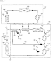
- FIG. 1 is a block diagram of a refrigeration system according to an embodiment of the present invention.
- FIG. 2 is a block diagram of an outdoor unit according to an embodiment of the present invention.
- a refrigeration system includes a refrigerator (IU) for refrigerating or cooling the storage, an air conditioner AC for cooling the room, an outdoor unit (OU) for compressing and condensing refrigerant to supply to the refrigerator (IU), and a liquid pipe 171 and an gas pipe 172 connecting the outdoor unit (OU) and the refrigerator (IU).
- Refrigerator (IU) is installed indoors, such as a mart, a convenience store, supermarket, or the like, to display and store the storage, such as food.
- the refrigerator (IU) expands and evaporates the refrigerant to refrigerate or freeze the storage.
- Refrigerator (IU) is provided with a plurality may be connected in parallel to the outdoor unit (OU).
- the inlet side of the refrigerator (IU) is connected to the liquid pipe 171, and the outlet side of the refrigerator (IU) is connected to the gas pipe 172.
- the refrigerator includes a refrigeration expansion valve 130 for expanding the refrigerant and a refrigeration heat exchanger 140 for evaporating the refrigerant expanded in the refrigeration expansion valve 130.
- the opening degree of the refrigeration expansion valve 130 is adjusted to expand the refrigerant condensed in the outdoor unit (OU).
- the inlet side of the refrigeration expansion valve 130 is connected to the liquid pipe 171 and the outlet side is connected to the refrigeration heat exchanger 140.
- the refrigerant expanded in the refrigeration expansion valve 130 flows to the refrigeration heat exchanger 140.
- the refrigeration heat exchanger 140 evaporates the refrigerant expanded in the refrigeration expansion valve 130 to cool the air.
- the inlet side of the refrigeration heat exchanger 140 is connected to the refrigeration expansion valve 130 and the outlet side is connected to the gas pipe 172.
- the refrigerant evaporated in the refrigeration heat exchanger 140 flows to the outdoor unit (OU) through the gas pipe 172.
- the air conditioner AC cools indoor air to cool the room.
- the air conditioner AC includes an air conditioning compressor 210 for compressing the refrigerant, an air conditioning condenser 220 for condensing the refrigerant compressed in the air conditioning compressor 210 by heat exchange with the outdoor air, an air conditioning expansion valve 230 for expanding the refrigerant condensed in the air conditioning condenser 220, and an air conditioning evaporator 240 for evaporating the refrigerant expanded in the air conditioning expansion valve 230 by heat exchange with the indoor air.
- the air conditioning compressor 210 and the air conditioning condenser 220 are installed outdoor, the air conditioning expansion valve 230 and the air conditioning evaporator 240 are installed indoor.
- the air conditioning evaporator 240 cools the room by evaporating the refrigerant.
- the refrigerant evaporated from the air conditioning evaporator 240 passes through a heat recovery unit 160 of the outdoor unit (OU) described later, and then flows to the air conditioning compressor 210.
- the outdoor unit (OU) is installed outdoor to compress and condense the refrigerant.
- a plurality of outdoor units (OUs) may be provided to be connected to the refrigerator (IU) in parallel.
- the inlet side of the outdoor unit (OU) is connected to the gas pipe 172 and the outlet side is connected to the liquid pipe 171.
- the outdoor unit (OU) includes a low pressure side compressor 111 for compressing a refrigerant, a high pressure side compressor 112 for compressing the refrigerant compressed by the low pressure side compressor 111, an outdoor heat exchanger 120 for condensing the refrigerant compressed by the high pressure side compressor 112, a heat recovery unit 160 for cooling the refrigerant condensed in the outdoor heat exchanger 120 by heat exchange with the refrigerant evaporated in the air conditioner AC, and a supercooler 150 for supercooling the refrigerant heat exchanged in the heat recovery unit 160.
- a low pressure side compressor 111 for compressing a refrigerant
- a high pressure side compressor 112 for compressing the refrigerant compressed by the low pressure side compressor 111
- an outdoor heat exchanger 120 for condensing the refrigerant compressed by the high pressure side compressor 112
- a heat recovery unit 160 for cooling the refrigerant condensed in the outdoor heat exchanger 120 by heat exchange with the refrigerant evaporated in the air
- the low pressure side compressor 111 compresses a low temperature low pressure refrigerant into a high temperature high pressure refrigerant.
- Various structures may be applied to the low pressure side compressor 111, and may be a reciprocating compressor using a cylinder and a piston or may be a scroll compressor using an orbiting scroll and a fixed scroll.
- the low pressure side compressor 111 compresses the refrigerant evaporated in the refrigerator (IU) and flowed into the gas pipe 172 and/or the refrigerant flowed into a bypass pipe 155 of the supercooler 150.
- the suction side of the low pressure side compressor 111 is connected to the gas pipe 172 and the bypass pipe 155, and the discharge side of the low pressure side compressor 111 is connected to an injection pipe 153 and the high pressure side compressor 112.
- the refrigerant compressed in the low pressure side compressor 111 flows to the high pressure side compressor 112.
- the high pressure side compressor 112 compresses the low temperature low pressure refrigerant into the high temperature high pressure refrigerant.
- Various structures may be applied to the high pressure side compressor 112, and may be a reciprocating compressor using a cylinder and a piston or a scroll compressor using an orbiting scroll and a fixed scroll.
- the high pressure side compressor 112 compresses the refrigerant compressed in the low pressure side compressor 111 and/or the refrigerant flowed into the injection pipe 153 of the supercooler 150.
- the suction side of the high pressure side compressor 112 is connected to the injection pipe 153 and the low pressure side compressor 111, and the discharge side of the high pressure side compressor 112 is connected to the outdoor heat exchanger 120.
- the refrigerant compressed in the low pressure side compressor 111 flows to the outdoor heat exchanger 120.
- the outdoor heat exchanger 120 condenses the refrigerant compressed in the high pressure side compressor 112.
- the outdoor heat exchanger 120 heat exchanges the outdoor air flowing to the outdoor heat exchanger 120 by a blower fan (not shown) with the refrigerant compressed in the high pressure side compressor 112.
- the inlet side of the outdoor heat exchanger 120 is connected to the high pressure side compressor 112, and the outlet side of the outdoor heat exchanger 120 is connected to the heat recovery unit 160.
- the heat recovery unit 160 heat-exchanges and cools the refrigerant condensed in the outdoor heat exchanger 120 with the refrigerant evaporated in the air conditioner AC.
- the heat recovery unit 160 is a tubular heat exchanger which heat exchanges the refrigerant flowing from the outdoor heat exchanger 120 to the supercooler with the refrigerant flowing from the air conditioner evaporator 240 of the air conditioner AC to the air conditioner compressor 210 of the air conditioner AC.
- the heat recovery unit 160 cools the refrigerant condensed in the outdoor heat exchanger 120 by the low temperature low pressure refrigerant evaporated in the air conditioner AC.
- a first inlet side of the heat recovery unit 160 is connected to the outdoor heat exchanger 120, a second inlet side is connected to the air conditioning evaporator 240 of the air conditioner AC, a first outlet side of the heat recovery unit 160 is connected to the supercooler 150, and a second outlet side is connected to the air conditioning compressor 210 of the air conditioner AC.
- the refrigerant cooled in the heat recovery unit 160 flows to the supercooler 150.
- the supercooler 150 cools the refrigerant condensed in the outdoor heat exchanger 120.
- the supercooler 150 expands a part of the refrigerant which is condensed in the outdoor heat exchanger 120 and then is cooled in the heat recovery unit 160, thereby cooling another part of the refrigerant which is condensed in the outdoor heat exchanger 120 and then is cooled in the heat recovery unit 160.
- the inlet side of the supercooler 150 is connected to the heat recovery, and the first outlet side of the supercooler 150 is connected to the liquid pipe 171.
- the second outlet side of the supercooler 150 is connected to the low pressure side compressor 111 and the high pressure side compressor 112.
- the refrigerant cooled in the supercooler 150 flows to the refrigerator (IU) through the liquid pipe 171, and the refrigerant expanded and evaporated in the supercooler 150 is flows to the low pressure side compressor 111 or the high pressure side compressor 112.
- the supercooler 150 may operate or may not operate according to the low pressure side discharge temperature measured by a low pressure side discharge temperature sensor 111a and/or the high pressure side discharge temperature measured by a high pressure side discharge temperature sensor 112a.
- the supercooler 150 includes a supercooling expansion valve 152 for expanding a part of the refrigerant cooled in the heat recovery unit 160, a supercooling heat exchanger 151 for cooling another part of the refrigerant cooled in the heat recovery unit 160 by exchanging heat with the refrigerant expanded in the supercooling expansion valve 152, a bypass valve 156 for guiding the refrigerant which is expanded in the supercooling expansion valve 152 and is evaporated in the supercooling heat exchanger 151 to the suction side of the low pressure side compressor 111 when opened, and an injection valve 154 for guiding the refrigerant which is expanded in the supercooling expansion valve 152 and is evaporated in the supercooling heat exchanger 151 to the suction side of the high pressure side compressor 112 when opened.
- a supercooling expansion valve 152 for expanding a part of the refrigerant cooled in the heat recovery unit 160
- a supercooling heat exchanger 151 for cooling another part of the refrigerant cooled in the heat recovery
- the supercooling expansion valve 152 is opened by a controller 10 to adjust the opening degree or is closed.
- the supercooling expansion valve 152 expands a part of the refrigerant cooled in the heat recovery unit 160 when opened.
- the inlet side of the supercooling expansion valve 152 is connected to the heat recovery unit 160, and the outlet side is connected to the supercooling heat exchanger 151.
- the supercooling expansion valve 152 may be opened or closed according to the low pressure side discharge temperature measured by the low pressure side discharge temperature sensor 111a and/or the high pressure side discharge temperature measured by the high pressure side discharge temperature sensor 112a.
- the supercooling heat exchanger 151 exchanges heat between the refrigerant expanded in the supercooling expansion valve 152 and another part of the refrigerant cooled in the heat recovery unit 160.
- the supercooling heat exchanger 151 evaporates the refrigerant expanded in the supercooling expansion valve 152 and cools another part of the refrigerant cooled in the heat recovery unit 160.
- the first inlet side of the supercooling heat exchanger 151 is connected to the heat recovery unit 160 and the first outlet side is connected to the liquid pipe 171.
- the second inlet side of the supercooling heat exchanger 151 is connected to the supercooling expansion valve 152 and the second outlet side is connected to a supercooling pipe 157.
- the refrigerant which is expanded in the supercooling expansion valve 152 and then is evaporated in the supercooling heat exchanger 151 flows.
- the inlet side of the supercooling pipe 157 is connected to the supercooling heat exchanger 151 and the outlet side is branched into the bypass pipe 155 and the injection pipe 153.
- the bypass pipe 155 connects the supercooling pipe 157 and the suction side of the low pressure side compressor 111.
- the bypass valve 156 is disposed in the bypass pipe 155.
- the bypass valve 156 is disposed in the bypass pipe 155 to control the flow of the refrigerant flowing through the bypass pipe 155.
- the bypass valve 156 guides the refrigerant evaporated in the supercooling heat exchanger 151 after being expanded in the supercooling expansion valve 152 to the low pressure side compressor 111 through the bypass pipe 155 when opened.
- the bypass valve 156 is opened and closed according to the low pressure side discharge temperature measured by the low pressure side discharge temperature sensor 111a.
- the injection pipe 153 connects the supercooling pipe 157 and the suction side (the discharge side of the low pressure side compressor 111) of the high pressure side compressor 112.
- the injection valve 154 is disposed in the injection pipe 153.
- the injection valve 154 is disposed in the injection pipe 153 to control the flow of the refrigerant flowing through the injection pipe 153.
- the injection valve 154 guides the refrigerant evaporated in the supercooling heat exchanger 151 after being expanded in the supercooling expansion valve 152 to the high pressure side compressor 112 through the injection pipe 153.
- the injection valve 154 is opened and closed according to the high pressure side discharge temperature measured by the high pressure side discharge temperature sensor 112a.
- the low pressure side discharge temperature sensor 111a measures the low pressure side discharge temperature, which is the temperature of the refrigerant discharged from the low pressure side compressor 111.
- the low pressure side discharge temperature sensor 111a is disposed in the outlet side of the low pressure side compressor 111.
- the low pressure side discharge temperature sensor 111a transmits the measured low pressure side discharge temperature to the controller 10.
- the high pressure side discharge temperature sensor 112a measures the high pressure side discharge temperature which is a temperature of the refrigerant discharged from the high pressure side compressor 112.
- the high pressure side discharge temperature sensor 112a is disposed in the outlet side of the high pressure side compressor 112.
- the high pressure side discharge temperature sensor 112a transmits the measured high pressure side discharge temperature to the controller 10.
- the controller 10 controls the operation of the outdoor unit (OU).
- the controller 10 controls the operation speed of the high pressure side compressor 112 and the low pressure side compressor 111 according to the user's setting, the pressure and/or temperature of the refrigerant.
- the controller 10 controls the supercooling expansion valve 152, the bypass valve 156, and the injection valve 154 according to the low pressure side discharge temperature measured by the low pressure side discharge temperature sensor 111a and/or the high pressure side discharge temperature measured by the high pressure side discharge temperature sensor 112a.
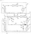
- FIG. 3 is a flowchart illustrating a control method of an outdoor unit according to an embodiment of the present invention
- FIG. 4 is a view showing flow of refrigerant in non-operation of a supercooler in an outdoor unit according to an embodiment of the present invention
- FIG. 5 is a view showing flow of refrigerant when opening a bypass valve in an outdoor unit according to an embodiment
- FIG. 6 is a view showing flow of refrigerant when opening an injection valve in an outdoor unit according to an embodiment
- FIG. 7 is a view showing flow of refrigerant when opening a bypass valve and an injection valve in an outdoor unit according to an embodiment.
- the embodiment disclosed in FIG. 3 is a control method of the outdoor unit performed in a state where the low pressure side discharge temperature T_o1 and the high pressure side discharge temperature T_o2 are normal.
- the supercooling expansion valve 152, the bypass valve 156, and the injection valve 154 of the supercooler 150 are closed in the state where the low pressure side discharge temperature T_o1 and the high pressure side discharge temperature T_o2 are normal.
- the refrigerant compressed in the air conditioning compressor 210 is condensed in the air conditioning condenser 220.
- the refrigerant condensed in the air conditioning condenser 220 is expanded in the air conditioning expansion valve 230 and then evaporated in the air conditioning evaporator 240 to cool the room.
- the refrigerant evaporated in the air conditioning evaporator 240 is heat-exchanged in the heat recovery unit 160 and then compressed in the air conditioning compressor 210.
- the refrigerant compressed by the low pressure side compressor 111 is recompressed by the high pressure side compressor 112.
- the refrigerant compressed by the high pressure side compressor 112 is condensed in the outdoor heat exchanger.
- the refrigerant condensed in the outdoor heat exchanger 120 is cooled by heat exchange with the refrigerant evaporated in the air conditioner AC in the heat recovery unit 160. Since the supercooling expansion valve 152 of the supercooler 150 is closed in the state where the low pressure side discharge temperature T_o1 and the high pressure side discharge temperature T_o2 are normal, the refrigerant cooled in the heat recovery unit 160 passes through the supercooler 150.
- the refrigerant passed through the supercooler 150 flows to the refrigerator (IU) through the liquid pipe 171.
- the refrigerant introduced into the refrigerator (IU) is expanded in the refrigeration expansion valve 130 and then evaporated in the refrigeration heat exchanger 140 to refrigerate or freeze the storage stored in the refrigerator (IU).
- the refrigerant evaporated in the refrigeration heat exchanger 140 flows to the outdoor unit (OU) through the gas pipe 172.
- the refrigerant introduced into the outdoor unit (OU) is compressed by the low pressure side compressor 111.
- the heat recovery unit 160 cools the refrigerant, so that supercooling is ensured.
- a sufficient amount of refrigerant may be introduced into the refrigerator (IU).
- the controller 10 determines whether the low pressure side discharge temperature T_o1 measured by the low pressure side discharge temperature sensor 111a is equal to or higher than a set low pressure side reference temperature T1 or whether the high pressure side discharge temperature T_o2 measured by the high pressure side discharge temperature sensor 112a is equal to or higher than a set high pressure side reference temperature T2 (S310).
- the controller 10 determines whether the low pressure side discharge temperature T_o1 or the high pressure side discharge temperature T_o2 is abnormally high.
- the controller 10 opens the supercooling expansion valve 152 (S320).
- the controller 10 opens the supercooling expansion valve 152 of the supercooler 150 to adjust the opening degree so that the supercooler 150 can cool the refrigerant.
- the controller 10 opens the bypass valve 156 (S340).
- the controller 10 determines that only the low pressure side discharge temperature T_o1 is abnormally high and the high pressure side discharge temperature T_o2 is normal, the controller 10 opens the bypass valve 156 of the supercooler 150, so that the refrigerant which is expanded in the supercooling expansion valve 152 and evaporated in the supercooling heat exchanger 151 flows to the low pressure side compressor 111.
- the supercooling expansion valve 152 When the supercooling expansion valve 152 is opened to adjust the opening degree, a part of the refrigerant cooled in the heat recovery unit 160 is expanded in the supercooling expansion valve 152 and then evaporated in the supercooling heat exchanger 151. Another part of the refrigerant cooled in the heat recovery unit 160 is cooled in the supercooling heat exchanger 151. The refrigerant cooled in the supercooler 150 flows to the refrigerator (IU) through the liquid pipe 171.
- the refrigerant evaporated in the supercooling heat exchanger 151 flows to the supercooling pipe 157. Since only the bypass valve 156 is opened, the refrigerant introduced into the supercooling pipe 157 flows into the low pressure side compressor 111 through the bypass pipe 155 and then is compressed.
- the low pressure side discharge temperature T_o1 may be reduced.
- the controller 10 opens the injection valve 154 (S360).
- the controller 10 opens the injection valve 154 of the supercooler 150 so that the refrigerant which is expanded in the supercooling expansion valve 152 and is evaporated in the supercooling heat exchanger 151 can flow to the high pressure side compressor 112.
- the supercooling expansion valve 152 When the supercooling expansion valve 152 is opened and the opening degree is adjusted, a part of the refrigerant cooled in the heat recovery unit 160 is expanded in the supercooling expansion valve 152 and then is evaporated in the supercooling heat exchanger 151. Another part of the refrigerant cooled in the heat recovery unit 160 is cooled in the supercooling heat exchanger 151. The refrigerant cooled in the supercooler 150 flows to the refrigerator (IU) through the liquid pipe 171.
- the refrigerant evaporated in the supercooling heat exchanger 151 flows to the supercooling pipe 157. Since only the injection valve 154 is opened, the refrigerant introduced into the supercooling pipe 157 flows into the high pressure side compressor 112 through the injection pipe 153 and is compressed.
- the high pressure side discharge temperature T_o2 may be reduced.
- the controller 10 opens the bypass valve 156 and the injection valve 154 (S370).
- the controller 10 opens the bypass valve 156 and the injection valve 154 of the supercooler 150 so that the refrigerant which is expanded in the supercooling expansion valve 152 and evaporated in the supercooling heat exchanger 151 flows to the low pressure side compressor 111 and the high pressure side compressor 112.
- the supercooling expansion valve 152 When the supercooling expansion valve 152 is opened and the opening degree is adjusted, a part of the refrigerant cooled in the heat recovery unit 160 is expanded in the supercooling expansion valve 152 and then is evaporated in the supercooling heat exchanger 151. Another part of the refrigerant cooled in the heat recovery unit 160 is cooled in the supercooling heat exchanger 151. The refrigerant cooled in the supercooler 150 flows to the refrigerator (IU) through the liquid pipe 171.
- the refrigerant evaporated in the supercooling heat exchanger 151 flows to the supercooling pipe 157. Since both the bypass valve 156 and the injection valve 154 are opened, a part of the refrigerant introduced into the supercooling pipe 157 is introduced into the low pressure side compressor 111 through the bypass pipe 155 and compressed, and another part flows into the high pressure side compressor 112 through the injection pipe 153 and is compressed.
- both the low pressure side discharge temperature T_o1 and the high pressure side discharge temperature T_o2 can be reduced.
- the controller 10 increases the opening degree of the supercooling expansion valve 152 than when only the low pressure side discharge temperature T_o1 or the high pressure side discharge temperature T_o2 is abnormal.
- the present invention can be utilized in various outdoor units that compress and condense refrigerant for various purposes such as refrigeration, freezing, cooling, and the like.
Landscapes
- Engineering & Computer Science (AREA)
- Physics & Mathematics (AREA)
- Thermal Sciences (AREA)
- Mechanical Engineering (AREA)
- General Engineering & Computer Science (AREA)
- Compression-Type Refrigeration Machines With Reversible Cycles (AREA)
- Air Conditioning Control Device (AREA)
Abstract
Description
- The present invention relates to an outdoor unit and a control method thereof, and more particularly, to an outdoor unit which is connected to a refrigerator and has two compressors that are connected in series, and a control method thereof.
- A refrigeration system is an apparatus that maintains the internal temperature of a refrigerator at a low temperature by using a cooling cycle consisting of a compressor, a condenser, an expander, and an evaporator.
- The refrigeration system includes a refrigerator for storing and displaying a storage such as food, and an outdoor unit which is installed outdoors and connected to the refrigerator through a refrigerant pipe. The outdoor unit is provided with a compressor and a condenser, and the refrigerator is provided with an expansion valve and an evaporator. The refrigeration system may be configured by connecting a single refrigerator and a single outdoor unit, or by a combination of a plurality of refrigerators and/or a plurality of outdoor units.
- In order to maintain the refrigerating performance of the refrigerator, such a refrigeration system should not allow the discharge temperature, which is the temperature of the refrigerant discharged from the compressor, to be excessively high. In particular, when the outdoor unit is difficult to directly control the refrigerator, it is not possible to control the expansion valve of the refrigerator. Therefore, it is important to manage the discharge temperature. In order to reduce the discharge temperature, the outdoor unit is provided with a supercooler for supercooling the refrigerant condensed in the condenser. However, in the case of increasing the supercooling performance of the supercooler under a high outdoor temperature, the amount of refrigerant, which is expanded in the supercooler, that is bypassed to the compressor becomes larger. Therefore, there is a problem that the refrigerating performance of the refrigerator is lowered and the efficiency of the entire system is lowered.
- An object of the present invention is to provide an outdoor unit capable of reducing the discharge temperature while reducing the bypass amount of the refrigerant through the supercooler, and a control method thereof.
- The objects of the present invention are not limited to the above-mentioned objects, and other objects that are not mentioned will be clearly understood by those skilled in the art from the following description.
- In order to achieve the above objects, an outdoor unit according to an embodiment of the present invention includes a low pressure side compressor for compressing a refrigerant; a high pressure side compressor for compressing the refrigerant compressed by the low pressure side compressor; an outdoor heat exchanger for condensing the refrigerant compressed by the high pressure side compressor; a heat recovery unit for cooling the refrigerant condensed in the outdoor heat exchanger by exchanging heat with the refrigerant evaporated in the air conditioner; and a supercooler for expanding a part of the refrigerant cooled in the heat recovery unit to cool another part of the refrigerant cooled in the heat recovery unit, so that the discharge temperature of the low pressure side compressor and/or the high pressure side compressor can be reduced.
- The supercooler includes a supercooling expansion valve for expanding a part of the refrigerant cooled in the heat recovery unit; a supercooling heat exchanger for cooling another part of the refrigerant cooled in the heat recovery unit by exchanging heat with the refrigerant expanded in the supercooling expansion valve; a bypass valve for guiding the refrigerant which is expanded in the supercooling expansion valve and evaporated in the supercooling heat exchanger to a suction side of the low pressure side compressor when opened; and an injection valve for guiding the refrigerant which is expanded in the supercooling expansion valve and evaporated in the supercooling heat exchanger to a suction side of the high-pressure side compressor when opened.
- The outdoor unit further includes a low pressure side discharge temperature sensor for measuring a low pressure side discharge temperature which is a temperature of the refrigerant discharged from the low pressure side compressor; and a high pressure side discharge temperature sensor for measuring a high pressure side discharge temperature which is a temperature of the refrigerant discharged from the high pressure side compressor, wherein the bypass valve is opened according to the low pressure side discharge temperature measured by the low pressure side discharge temperature sensor, and the injection valve is opened according to the high pressure side discharge temperature measured by the high pressure side discharge temperature sensor.
- The injection expansion valve is opened and closed according to the low pressure side discharge temperature measured by the low pressure side discharge temperature sensor and the high pressure side discharge temperature measured by the high pressure side discharge temperature sensor.
- The injection expansion valve has a higher opening degree when both the bypass valve and the injection valve are opened than when only the bypass valve or the injection valve is opened.
- In order to achieve the above objects, a method of controlling an outdoor unit includes a discharge temperature measuring step of measuring a low pressure side discharge temperature which is a temperature of a refrigerant discharged from the low pressure side compressor, and a high pressure side discharge temperature which is a temperature of a refrigerant discharged from the high pressure side compressor; and a supercooling step of guiding the refrigerant expanded in the supercooler to a suction side of the low pressure side compressor or a suction side of the high pressure side compressor according to the low pressure side discharge temperature or the high pressure side discharge temperature, so that the discharge temperature of the low pressure side compressor and/or the high pressure side compressor can be reduced.
- The supercooling step includes: opening the supercooling expansion valve according to the low pressure side discharge temperature and the high pressure side discharge temperature; opening the bypass valve according to the low pressure side discharge temperature; and opening the injection valve according to the high pressure side discharge temperature.
- The outdoor unit and the control method thereof according to the present invention have one or more of the following effects.
- First, there is an advantage in that the discharge temperature of the low pressure side compressor and/or the high pressure side compressor can be reduced without reducing the amount of refrigerant flowing into the refrigerator.
- Second, there is an advantage in that when the discharge temperature of only one of the high pressure side compressor and the low pressure side compressor is high, it is possible to reduce the discharge temperature while ensuring the maximum amount of refrigerant flowing into the refrigerator by introducing the refrigerant expanded and evaporated in the supercooler only to a corresponding compressor.
- Third, there is also an advantage of improving the cycle efficiency and increasing the refrigerating performance of the refrigerator by ensuring the amount of the refrigerant flowing into the refrigerator even under high outdoor temperature conditions.
- The effects of the present invention are not limited to the effects mentioned above, and other effects not mentioned can be clearly understood by those skilled in the art from the description of the claims.
-
-
FIG. 1 is a block diagram of a refrigeration system according to an embodiment of the present invention. -
FIG. 2 is a block diagram of an outdoor unit according to an embodiment of the present invention. -
FIG. 3 is a flowchart illustrating a control method of an outdoor unit according to an embodiment of the present invention. -
FIG. 4 is a view showing flow of refrigerant in non-operation of a supercooler in an outdoor unit according to an embodiment of the present invention. -
FIG. 5 is a view showing flow of refrigerant when opening a bypass valve in an outdoor unit according to an embodiment. -
FIG. 6 is a view showing flow of refrigerant when opening an injection valve in an outdoor unit according to an embodiment. -
FIG. 7 is a view showing flow of refrigerant when opening a bypass valve and an injection valve in an outdoor unit according to an embodiment. - Prior to a detailed description of the present invention, terms and words used in the specification and the claims shall not be interpreted as commonly-used dictionary meanings, but shall be interpreted as to be relevant to the technical scope of the invention based on the fact that the inventor may property define the concept of the terms to explain the invention in best ways. Therefore, the embodiments and the configurations depicted in the drawings are illustrative purposes only and do not represent all technical scopes of the embodiments, so it should be understood that various equivalents and modifications may exist at the time of filing this application. In describing the present embodiment, the same designations and the same reference numerals are used for the same components, and further description thereof will be omitted.
- Hereinafter, the present invention will be described with reference to the drawings for illustrating an outdoor unit and a control method thereof according to embodiments of the present invention.
-
FIG. 1 is a block diagram of a refrigeration system according to an embodiment of the present invention.FIG. 2 is a block diagram of an outdoor unit according to an embodiment of the present invention. - A refrigeration system according to an embodiment of the present invention includes a refrigerator (IU) for refrigerating or cooling the storage, an air conditioner AC for cooling the room, an outdoor unit (OU) for compressing and condensing refrigerant to supply to the refrigerator (IU), and a
liquid pipe 171 and angas pipe 172 connecting the outdoor unit (OU) and the refrigerator (IU). - Refrigerator (IU) is installed indoors, such as a mart, a convenience store, supermarket, or the like, to display and store the storage, such as food. The refrigerator (IU) expands and evaporates the refrigerant to refrigerate or freeze the storage. Refrigerator (IU) is provided with a plurality may be connected in parallel to the outdoor unit (OU). The inlet side of the refrigerator (IU) is connected to the
liquid pipe 171, and the outlet side of the refrigerator (IU) is connected to thegas pipe 172. - The refrigerator (IU) includes a
refrigeration expansion valve 130 for expanding the refrigerant and arefrigeration heat exchanger 140 for evaporating the refrigerant expanded in therefrigeration expansion valve 130. - The opening degree of the
refrigeration expansion valve 130 is adjusted to expand the refrigerant condensed in the outdoor unit (OU). The inlet side of therefrigeration expansion valve 130 is connected to theliquid pipe 171 and the outlet side is connected to therefrigeration heat exchanger 140. The refrigerant expanded in therefrigeration expansion valve 130 flows to therefrigeration heat exchanger 140. - The
refrigeration heat exchanger 140 evaporates the refrigerant expanded in therefrigeration expansion valve 130 to cool the air. The inlet side of therefrigeration heat exchanger 140 is connected to therefrigeration expansion valve 130 and the outlet side is connected to thegas pipe 172. The refrigerant evaporated in therefrigeration heat exchanger 140 flows to the outdoor unit (OU) through thegas pipe 172. - The air conditioner AC cools indoor air to cool the room. The air conditioner AC includes an
air conditioning compressor 210 for compressing the refrigerant, anair conditioning condenser 220 for condensing the refrigerant compressed in theair conditioning compressor 210 by heat exchange with the outdoor air, an airconditioning expansion valve 230 for expanding the refrigerant condensed in theair conditioning condenser 220, and anair conditioning evaporator 240 for evaporating the refrigerant expanded in the airconditioning expansion valve 230 by heat exchange with the indoor air. Theair conditioning compressor 210 and theair conditioning condenser 220 are installed outdoor, the airconditioning expansion valve 230 and theair conditioning evaporator 240 are installed indoor. Theair conditioning evaporator 240 cools the room by evaporating the refrigerant. The refrigerant evaporated from theair conditioning evaporator 240 passes through aheat recovery unit 160 of the outdoor unit (OU) described later, and then flows to theair conditioning compressor 210. - The outdoor unit (OU) is installed outdoor to compress and condense the refrigerant. A plurality of outdoor units (OUs) may be provided to be connected to the refrigerator (IU) in parallel. The inlet side of the outdoor unit (OU) is connected to the
gas pipe 172 and the outlet side is connected to theliquid pipe 171. - The outdoor unit (OU) includes a low
pressure side compressor 111 for compressing a refrigerant, a highpressure side compressor 112 for compressing the refrigerant compressed by the lowpressure side compressor 111, anoutdoor heat exchanger 120 for condensing the refrigerant compressed by the highpressure side compressor 112, aheat recovery unit 160 for cooling the refrigerant condensed in theoutdoor heat exchanger 120 by heat exchange with the refrigerant evaporated in the air conditioner AC, and asupercooler 150 for supercooling the refrigerant heat exchanged in theheat recovery unit 160. - The low
pressure side compressor 111 compresses a low temperature low pressure refrigerant into a high temperature high pressure refrigerant. Various structures may be applied to the lowpressure side compressor 111, and may be a reciprocating compressor using a cylinder and a piston or may be a scroll compressor using an orbiting scroll and a fixed scroll. - The low
pressure side compressor 111 compresses the refrigerant evaporated in the refrigerator (IU) and flowed into thegas pipe 172 and/or the refrigerant flowed into abypass pipe 155 of thesupercooler 150. The suction side of the lowpressure side compressor 111 is connected to thegas pipe 172 and thebypass pipe 155, and the discharge side of the lowpressure side compressor 111 is connected to aninjection pipe 153 and the highpressure side compressor 112. The refrigerant compressed in the lowpressure side compressor 111 flows to the highpressure side compressor 112. - The high
pressure side compressor 112 compresses the low temperature low pressure refrigerant into the high temperature high pressure refrigerant. Various structures may be applied to the highpressure side compressor 112, and may be a reciprocating compressor using a cylinder and a piston or a scroll compressor using an orbiting scroll and a fixed scroll. - The high
pressure side compressor 112 compresses the refrigerant compressed in the lowpressure side compressor 111 and/or the refrigerant flowed into theinjection pipe 153 of thesupercooler 150. The suction side of the highpressure side compressor 112 is connected to theinjection pipe 153 and the lowpressure side compressor 111, and the discharge side of the highpressure side compressor 112 is connected to theoutdoor heat exchanger 120. The refrigerant compressed in the lowpressure side compressor 111 flows to theoutdoor heat exchanger 120. - The
outdoor heat exchanger 120 condenses the refrigerant compressed in the highpressure side compressor 112. Theoutdoor heat exchanger 120 heat exchanges the outdoor air flowing to theoutdoor heat exchanger 120 by a blower fan (not shown) with the refrigerant compressed in the highpressure side compressor 112. The inlet side of theoutdoor heat exchanger 120 is connected to the highpressure side compressor 112, and the outlet side of theoutdoor heat exchanger 120 is connected to theheat recovery unit 160. - The
heat recovery unit 160 heat-exchanges and cools the refrigerant condensed in theoutdoor heat exchanger 120 with the refrigerant evaporated in the air conditioner AC. Theheat recovery unit 160 is a tubular heat exchanger which heat exchanges the refrigerant flowing from theoutdoor heat exchanger 120 to the supercooler with the refrigerant flowing from theair conditioner evaporator 240 of the air conditioner AC to theair conditioner compressor 210 of the air conditioner AC. Theheat recovery unit 160 cools the refrigerant condensed in theoutdoor heat exchanger 120 by the low temperature low pressure refrigerant evaporated in the air conditioner AC. A first inlet side of theheat recovery unit 160 is connected to theoutdoor heat exchanger 120, a second inlet side is connected to theair conditioning evaporator 240 of the air conditioner AC, a first outlet side of theheat recovery unit 160 is connected to thesupercooler 150, and a second outlet side is connected to theair conditioning compressor 210 of the air conditioner AC. The refrigerant cooled in theheat recovery unit 160 flows to thesupercooler 150. - The
supercooler 150 cools the refrigerant condensed in theoutdoor heat exchanger 120. Thesupercooler 150 expands a part of the refrigerant which is condensed in theoutdoor heat exchanger 120 and then is cooled in theheat recovery unit 160, thereby cooling another part of the refrigerant which is condensed in theoutdoor heat exchanger 120 and then is cooled in theheat recovery unit 160. The inlet side of thesupercooler 150 is connected to the heat recovery, and the first outlet side of thesupercooler 150 is connected to theliquid pipe 171. The second outlet side of thesupercooler 150 is connected to the lowpressure side compressor 111 and the highpressure side compressor 112. The refrigerant cooled in thesupercooler 150 flows to the refrigerator (IU) through theliquid pipe 171, and the refrigerant expanded and evaporated in thesupercooler 150 is flows to the lowpressure side compressor 111 or the highpressure side compressor 112. Thesupercooler 150 may operate or may not operate according to the low pressure side discharge temperature measured by a low pressure sidedischarge temperature sensor 111a and/or the high pressure side discharge temperature measured by a high pressure sidedischarge temperature sensor 112a. - The
supercooler 150 includes asupercooling expansion valve 152 for expanding a part of the refrigerant cooled in theheat recovery unit 160, asupercooling heat exchanger 151 for cooling another part of the refrigerant cooled in theheat recovery unit 160 by exchanging heat with the refrigerant expanded in thesupercooling expansion valve 152, abypass valve 156 for guiding the refrigerant which is expanded in thesupercooling expansion valve 152 and is evaporated in thesupercooling heat exchanger 151 to the suction side of the lowpressure side compressor 111 when opened, and aninjection valve 154 for guiding the refrigerant which is expanded in thesupercooling expansion valve 152 and is evaporated in thesupercooling heat exchanger 151 to the suction side of the highpressure side compressor 112 when opened. - The supercooling
expansion valve 152 is opened by acontroller 10 to adjust the opening degree or is closed. The supercoolingexpansion valve 152 expands a part of the refrigerant cooled in theheat recovery unit 160 when opened. The inlet side of thesupercooling expansion valve 152 is connected to theheat recovery unit 160, and the outlet side is connected to thesupercooling heat exchanger 151. The supercoolingexpansion valve 152 may be opened or closed according to the low pressure side discharge temperature measured by the low pressure sidedischarge temperature sensor 111a and/or the high pressure side discharge temperature measured by the high pressure sidedischarge temperature sensor 112a. - The supercooling
heat exchanger 151 exchanges heat between the refrigerant expanded in thesupercooling expansion valve 152 and another part of the refrigerant cooled in theheat recovery unit 160. The supercoolingheat exchanger 151 evaporates the refrigerant expanded in thesupercooling expansion valve 152 and cools another part of the refrigerant cooled in theheat recovery unit 160. - The first inlet side of the
supercooling heat exchanger 151 is connected to theheat recovery unit 160 and the first outlet side is connected to theliquid pipe 171. The second inlet side of thesupercooling heat exchanger 151 is connected to thesupercooling expansion valve 152 and the second outlet side is connected to asupercooling pipe 157. - In the
supercooling pipe 157, the refrigerant which is expanded in thesupercooling expansion valve 152 and then is evaporated in thesupercooling heat exchanger 151 flows. The inlet side of thesupercooling pipe 157 is connected to thesupercooling heat exchanger 151 and the outlet side is branched into thebypass pipe 155 and theinjection pipe 153. - The
bypass pipe 155 connects thesupercooling pipe 157 and the suction side of the lowpressure side compressor 111. Thebypass valve 156 is disposed in thebypass pipe 155. - The
bypass valve 156 is disposed in thebypass pipe 155 to control the flow of the refrigerant flowing through thebypass pipe 155. Thebypass valve 156 guides the refrigerant evaporated in thesupercooling heat exchanger 151 after being expanded in thesupercooling expansion valve 152 to the lowpressure side compressor 111 through thebypass pipe 155 when opened. Thebypass valve 156 is opened and closed according to the low pressure side discharge temperature measured by the low pressure sidedischarge temperature sensor 111a. - The
injection pipe 153 connects thesupercooling pipe 157 and the suction side (the discharge side of the low pressure side compressor 111) of the highpressure side compressor 112. Theinjection valve 154 is disposed in theinjection pipe 153. - The
injection valve 154 is disposed in theinjection pipe 153 to control the flow of the refrigerant flowing through theinjection pipe 153. Theinjection valve 154 guides the refrigerant evaporated in thesupercooling heat exchanger 151 after being expanded in thesupercooling expansion valve 152 to the highpressure side compressor 112 through theinjection pipe 153. Theinjection valve 154 is opened and closed according to the high pressure side discharge temperature measured by the high pressure sidedischarge temperature sensor 112a. - The low pressure side
discharge temperature sensor 111a measures the low pressure side discharge temperature, which is the temperature of the refrigerant discharged from the lowpressure side compressor 111. The low pressure sidedischarge temperature sensor 111a is disposed in the outlet side of the lowpressure side compressor 111. The low pressure sidedischarge temperature sensor 111a transmits the measured low pressure side discharge temperature to thecontroller 10. - The high pressure side
discharge temperature sensor 112a measures the high pressure side discharge temperature which is a temperature of the refrigerant discharged from the highpressure side compressor 112. The high pressure sidedischarge temperature sensor 112a is disposed in the outlet side of the highpressure side compressor 112. The high pressure sidedischarge temperature sensor 112a transmits the measured high pressure side discharge temperature to thecontroller 10. - The
controller 10 controls the operation of the outdoor unit (OU). Thecontroller 10 controls the operation speed of the highpressure side compressor 112 and the lowpressure side compressor 111 according to the user's setting, the pressure and/or temperature of the refrigerant. Thecontroller 10 controls thesupercooling expansion valve 152, thebypass valve 156, and theinjection valve 154 according to the low pressure side discharge temperature measured by the low pressure sidedischarge temperature sensor 111a and/or the high pressure side discharge temperature measured by the high pressure sidedischarge temperature sensor 112a. -
FIG. 3 is a flowchart illustrating a control method of an outdoor unit according to an embodiment of the present invention,FIG. 4 is a view showing flow of refrigerant in non-operation of a supercooler in an outdoor unit according to an embodiment of the present invention,FIG. 5 is a view showing flow of refrigerant when opening a bypass valve in an outdoor unit according to an embodiment,FIG. 6 is a view showing flow of refrigerant when opening an injection valve in an outdoor unit according to an embodiment, andFIG. 7 is a view showing flow of refrigerant when opening a bypass valve and an injection valve in an outdoor unit according to an embodiment. - The embodiment disclosed in
FIG. 3 is a control method of the outdoor unit performed in a state where the low pressure side discharge temperature T_o1 and the high pressure side discharge temperature T_o2 are normal. The supercoolingexpansion valve 152, thebypass valve 156, and theinjection valve 154 of thesupercooler 150 are closed in the state where the low pressure side discharge temperature T_o1 and the high pressure side discharge temperature T_o2 are normal. - Hereinafter, the flow of the refrigerant in the state where the low pressure side discharge temperature T_o1 and the high pressure side discharge temperature T_o2 are normal will be described with reference to
FIG. 4 . - First, the flow of the refrigerant of the air conditioner AC will be described. The refrigerant compressed in the
air conditioning compressor 210 is condensed in theair conditioning condenser 220. The refrigerant condensed in theair conditioning condenser 220 is expanded in the airconditioning expansion valve 230 and then evaporated in theair conditioning evaporator 240 to cool the room. The refrigerant evaporated in theair conditioning evaporator 240 is heat-exchanged in theheat recovery unit 160 and then compressed in theair conditioning compressor 210. - Meanwhile, the refrigerant compressed by the low
pressure side compressor 111 is recompressed by the highpressure side compressor 112. The refrigerant compressed by the highpressure side compressor 112 is condensed in the outdoor heat exchanger. The refrigerant condensed in theoutdoor heat exchanger 120 is cooled by heat exchange with the refrigerant evaporated in the air conditioner AC in theheat recovery unit 160. Since thesupercooling expansion valve 152 of thesupercooler 150 is closed in the state where the low pressure side discharge temperature T_o1 and the high pressure side discharge temperature T_o2 are normal, the refrigerant cooled in theheat recovery unit 160 passes through thesupercooler 150. The refrigerant passed through thesupercooler 150 flows to the refrigerator (IU) through theliquid pipe 171. - The refrigerant introduced into the refrigerator (IU) is expanded in the
refrigeration expansion valve 130 and then evaporated in therefrigeration heat exchanger 140 to refrigerate or freeze the storage stored in the refrigerator (IU). The refrigerant evaporated in therefrigeration heat exchanger 140 flows to the outdoor unit (OU) through thegas pipe 172. The refrigerant introduced into the outdoor unit (OU) is compressed by the lowpressure side compressor 111. - Even if the
supercooler 150 does not cool the refrigerant in the above-described process, theheat recovery unit 160 cools the refrigerant, so that supercooling is ensured. In addition, since there is no refrigerant flowing into the lowpressure side compressor 111 or the highpressure side compressor 112 through thesupercooler 150, a sufficient amount of refrigerant may be introduced into the refrigerator (IU). - The control method of the outdoor unit according to an embodiment of the present invention will be described with reference to
FIG. 3 . - The
controller 10 determines whether the low pressure side discharge temperature T_o1 measured by the low pressure sidedischarge temperature sensor 111a is equal to or higher than a set low pressure side reference temperature T1 or whether the high pressure side discharge temperature T_o2 measured by the high pressure sidedischarge temperature sensor 112a is equal to or higher than a set high pressure side reference temperature T2 (S310). - When the temperature T_o1 of the refrigerant discharged from the low
pressure side compressor 111 measured by the low pressure sidedischarge temperature sensor 111a or the temperature T_o2 of the refrigerant discharged from the highpressure side compressor 112 measured by the high pressure sidedischarge temperature sensor 112a is too high, the system efficiency may be lowered and the refrigeration performance may be deteriorated. Therefore, thecontroller 10 determines whether the low pressure side discharge temperature T_o1 or the high pressure side discharge temperature T_o2 is abnormally high. - When the low pressure side discharge temperature T_o1 measured by the low pressure side
discharge temperature sensor 111a is equal to or higher than the set low pressure side reference temperature T1, or when the high pressure side discharge temperature T_o2 measured by the high pressure sidedischarge temperature sensor 112a is equal to or higher than the set high pressure side reference temperature T2, thecontroller 10 opens the supercooling expansion valve 152 (S320). When determining that the low pressure side discharge temperature T_o1 or the high pressure side discharge temperature T_o2 is abnormally high, thecontroller 10 opens thesupercooling expansion valve 152 of thesupercooler 150 to adjust the opening degree so that thesupercooler 150 can cool the refrigerant. - When the low pressure side discharge temperature T_o1 is equal to or higher than the set low pressure side reference temperature T1 but the high pressure side discharge temperature T_o2 is lower than the set high pressure side reference temperature T2 (S330), the
controller 10 opens the bypass valve 156 (S340). When thecontroller 10 determines that only the low pressure side discharge temperature T_o1 is abnormally high and the high pressure side discharge temperature T_o2 is normal, thecontroller 10 opens thebypass valve 156 of thesupercooler 150, so that the refrigerant which is expanded in thesupercooling expansion valve 152 and evaporated in thesupercooling heat exchanger 151 flows to the lowpressure side compressor 111. - The flow of refrigerant different from
FIG. 4 will be described with reference toFIG. 5 in a state where the low pressure side discharge temperature T_o1 is abnormal and the high pressure side discharge temperature T_o2 is normal. - When the
supercooling expansion valve 152 is opened to adjust the opening degree, a part of the refrigerant cooled in theheat recovery unit 160 is expanded in thesupercooling expansion valve 152 and then evaporated in thesupercooling heat exchanger 151. Another part of the refrigerant cooled in theheat recovery unit 160 is cooled in thesupercooling heat exchanger 151. The refrigerant cooled in thesupercooler 150 flows to the refrigerator (IU) through theliquid pipe 171. - The refrigerant evaporated in the
supercooling heat exchanger 151 flows to thesupercooling pipe 157. Since only thebypass valve 156 is opened, the refrigerant introduced into thesupercooling pipe 157 flows into the lowpressure side compressor 111 through thebypass pipe 155 and then is compressed. - Since the refrigerant which is evaporated after being expanded in the
supercooler 150 flows into the lowpressure side compressor 111, the low pressure side discharge temperature T_o1 may be reduced. - When the high pressure side discharge temperature T_o2 is equal to or higher than the set high pressure side reference temperature T2 or when the low pressure side discharge temperature T_o1 is lower than the set high pressure side reference temperature T1 (S350), the
controller 10 opens the injection valve 154 (S360). When determining that only the high pressure side discharge temperature T_o2 is abnormally high and the low pressure side discharge temperature T_o1 is normal, thecontroller 10 opens theinjection valve 154 of thesupercooler 150 so that the refrigerant which is expanded in thesupercooling expansion valve 152 and is evaporated in thesupercooling heat exchanger 151 can flow to the highpressure side compressor 112. - The flow of refrigerant different from
FIG. 4 will be described with reference toFIG. 6 in a state where the high pressure side discharge temperature T_o2 is abnormal and the low pressure side discharge temperature T_o1 is normal. - When the
supercooling expansion valve 152 is opened and the opening degree is adjusted, a part of the refrigerant cooled in theheat recovery unit 160 is expanded in thesupercooling expansion valve 152 and then is evaporated in thesupercooling heat exchanger 151. Another part of the refrigerant cooled in theheat recovery unit 160 is cooled in thesupercooling heat exchanger 151. The refrigerant cooled in thesupercooler 150 flows to the refrigerator (IU) through theliquid pipe 171. - The refrigerant evaporated in the
supercooling heat exchanger 151 flows to thesupercooling pipe 157. Since only theinjection valve 154 is opened, the refrigerant introduced into thesupercooling pipe 157 flows into the highpressure side compressor 112 through theinjection pipe 153 and is compressed. - Since the refrigerant which is evaporated after being expanded in the
supercooler 150 is introduced into the highpressure side compressor 112, the high pressure side discharge temperature T_o2 may be reduced. - When the low pressure side discharge temperature T_o1 is equal to or higher than the set low pressure side reference temperature T1 and the high pressure side discharge temperature T_o2 is also equal to or higher than the set high pressure side reference temperature T2, the
controller 10 opens thebypass valve 156 and the injection valve 154 (S370). When determining that both the low pressure side discharge temperature T_o1 and the high pressure side discharge temperature T_o2 are abnormally high, thecontroller 10 opens thebypass valve 156 and theinjection valve 154 of thesupercooler 150 so that the refrigerant which is expanded in thesupercooling expansion valve 152 and evaporated in thesupercooling heat exchanger 151 flows to the lowpressure side compressor 111 and the highpressure side compressor 112. - The flow of refrigerant different from
FIG. 4 will be described with reference toFIG. 7 in a state where the low pressure side discharge temperature T_o1 and the high pressure side discharge temperature T_o2 are abnormal. - When the
supercooling expansion valve 152 is opened and the opening degree is adjusted, a part of the refrigerant cooled in theheat recovery unit 160 is expanded in thesupercooling expansion valve 152 and then is evaporated in thesupercooling heat exchanger 151. Another part of the refrigerant cooled in theheat recovery unit 160 is cooled in thesupercooling heat exchanger 151. The refrigerant cooled in thesupercooler 150 flows to the refrigerator (IU) through theliquid pipe 171. - The refrigerant evaporated in the
supercooling heat exchanger 151 flows to thesupercooling pipe 157. Since both thebypass valve 156 and theinjection valve 154 are opened, a part of the refrigerant introduced into thesupercooling pipe 157 is introduced into the lowpressure side compressor 111 through thebypass pipe 155 and compressed, and another part flows into the highpressure side compressor 112 through theinjection pipe 153 and is compressed. - Since the refrigerant which is evaporated after being expanded in the
supercooler 150 flows into the lowpressure side compressor 111 and the highpressure side compressor 112, both the low pressure side discharge temperature T_o1 and the high pressure side discharge temperature T_o2 can be reduced. - Even if the amount of refrigerant flowing into the refrigerator (IU) is reduced, it is necessary to reduce both the low pressure side discharge temperature T_o1 and the high pressure side discharge temperature T_o2. Therefore, when both the low pressure side discharge temperature T_o1 and the high pressure side discharge temperature T_o2 are abnormal, it is preferable that the
controller 10 increases the opening degree of thesupercooling expansion valve 152 than when only the low pressure side discharge temperature T_o1 or the high pressure side discharge temperature T_o2 is abnormal. - Although the exemplary embodiments of the present invention have been disclosed for illustrative purposes, those skilled in the art will appreciate that various modifications, additions and substitutions are possible, without departing from the scope and spirit of the invention as disclosed in the accompanying claims. Accordingly, the scope of the present invention is not construed as being limited to the described embodiments but is defined by the appended claims as well as equivalents thereto.
- The present invention can be utilized in various outdoor units that compress and condense refrigerant for various purposes such as refrigeration, freezing, cooling, and the like.
Claims (7)
- An outdoor unit connected to a refrigerator for refrigerating storage and an air conditioner for cooling a room, the outdoor unit comprising:a low pressure side compressor for compressing a refrigerant;a high pressure side compressor for compressing the refrigerant compressed by the low pressure side compressor;an outdoor heat exchanger for condensing the refrigerant compressed by the high pressure side compressor;a heat recovery unit for cooling the refrigerant condensed in the outdoor heat exchanger by exchanging heat with the refrigerant evaporated in the air conditioner; anda supercooler for expanding a part of the refrigerant cooled in the heat recovery unit to cool another part of the refrigerant cooled in the heat recovery unit.
- The outdoor unit of claim 1, wherein the supercooler comprises:a supercooling expansion valve for expanding a part of the refrigerant cooled in the heat recovery unit;a supercooling heat exchanger for cooling another part of the refrigerant cooled in the heat recovery unit by exchanging heat with the refrigerant expanded in the supercooling expansion valve;a bypass valve for guiding the refrigerant which is expanded in the supercooling expansion valve and evaporated in the supercooling heat exchanger to a suction side of the low pressure side compressor when opened; andan injection valve for guiding the refrigerant which is expanded in the supercooling expansion valve and evaporated in the supercooling heat exchanger to a suction side of the high-pressure side compressor when opened.
- The outdoor unit of claim 2, further comprising:a low pressure side discharge temperature sensor for measuring a low pressure side discharge temperature which is a temperature of the refrigerant discharged from the low pressure side compressor; anda high pressure side discharge temperature sensor for measuring a high pressure side discharge temperature which is a temperature of the refrigerant discharged from the high pressure side compressor,wherein the bypass valve is opened according to the low pressure side discharge temperature measured by the low pressure side discharge temperature sensor, and the injection valve is opened according to the high pressure side discharge temperature measured by the high pressure side discharge temperature sensor.
- The outdoor unit of claim 3, wherein the injection expansion valve is opened and closed according to the low pressure side discharge temperature measured by the low pressure side discharge temperature sensor and the high pressure side discharge temperature measured by the high pressure side discharge temperature sensor.
- The outdoor unit of claim 3, wherein the injection expansion valve has a higher opening degree when both the bypass valve and the injection valve are opened than when only the bypass valve or the injection valve is opened.
- A method of controlling an outdoor unit which is connected to a refrigerator for refrigerating storage and an air conditioner for cooling a room and comprises a low pressure side compressor, a high pressure side compressor, an outdoor heat exchanger, a heat recovery unit for cooling the refrigerant condensed in the outdoor heat exchanger by exchanging heat with the refrigerant evaporated in the air conditioner, and a supercooler for expanding a part of the refrigerant cooled in the heat recovery unit to cool another part of the refrigerant cooled in the heat recovery unit, the method comprising:a discharge temperature measuring step of measuring a low pressure side discharge temperature which is a temperature of a refrigerant discharged from the low pressure side compressor, and a high pressure side discharge temperature which is a temperature of a refrigerant discharged from the high pressure side compressor; anda supercooling step of guiding the refrigerant expanded in the supercooler to a suction side of the low pressure side compressor or a suction side of the high pressure side compressor according to the low pressure side discharge temperature or the high pressure side discharge temperature.
- The outdoor unit of claim 6, wherein the supercooler comprises:a supercooling expansion valve for expanding a part of the refrigerant cooled in the heat recovery unit;a supercooling heat exchanger for cooling another part of the refrigerant cooled in the heat recovery unit by exchanging heat with the refrigerant expanded in the supercooling expansion valve;a bypass valve for guiding the refrigerant which is expanded in the supercooling expansion valve and evaporated in the supercooling heat exchanger to a suction side of the low pressure side compressor when opened; andan injection valve for guiding the refrigerant which is expanded in the supercooling expansion valve and evaporated in the supercooling heat exchanger to a suction side of the high-pressure side compressor when opened,wherein the supercooling step comprises the steps of:opening the supercooling expansion valve according to the low pressure side discharge temperature and the high pressure side discharge temperature;opening the bypass valve according to the low pressure side discharge temperature; andopening the injection valve according to the high pressure side discharge temperature.
Applications Claiming Priority (2)
| Application Number | Priority Date | Filing Date | Title |
|---|---|---|---|
| KR1020170055474A KR101909531B1 (en) | 2017-04-28 | 2017-04-28 | Outdoor unit and Controlling method therefor |
| PCT/KR2018/004910 WO2018199682A1 (en) | 2017-04-28 | 2018-04-27 | Outdoor unit and method for controlling same |
Publications (3)
| Publication Number | Publication Date |
|---|---|
| EP3617617A1 true EP3617617A1 (en) | 2020-03-04 |
| EP3617617A4 EP3617617A4 (en) | 2020-12-09 |
| EP3617617B1 EP3617617B1 (en) | 2025-02-19 |
Family
ID=63919911
Family Applications (1)
| Application Number | Title | Priority Date | Filing Date |
|---|---|---|---|
| EP18792077.2A Active EP3617617B1 (en) | 2017-04-28 | 2018-04-27 | Outdoor unit and method for controlling same |
Country Status (4)
| Country | Link |
|---|---|
| US (1) | US11402134B2 (en) |
| EP (1) | EP3617617B1 (en) |
| KR (1) | KR101909531B1 (en) |
| WO (1) | WO2018199682A1 (en) |
Cited By (1)
| Publication number | Priority date | Publication date | Assignee | Title |
|---|---|---|---|---|
| WO2022199862A1 (en) * | 2021-03-23 | 2022-09-29 | Aircodue S.R.L. | Environmental air conditioning and heating plant |
Families Citing this family (5)
| Publication number | Priority date | Publication date | Assignee | Title |
|---|---|---|---|---|
| KR102128576B1 (en) * | 2018-11-15 | 2020-06-30 | 엘지전자 주식회사 | Refrigerant cycle apparatus |
| CN111207504A (en) * | 2020-01-13 | 2020-05-29 | 珠海格力电器股份有限公司 | Air conditioning system and refrigerant recovery control method |
| RU2743653C1 (en) * | 2020-05-21 | 2021-02-20 | Акционерное общество "Центральный научно-исследовательский институт "Курс" | Cascade refrigerating machine with compressor thermal stabilization system |
| CN117267971A (en) * | 2022-10-31 | 2023-12-22 | 付朝乾 | Two-stage compression three-stage cascade type cold and hot double-supply heat pump |
| CN119289585A (en) * | 2023-07-10 | 2025-01-10 | 开利公司 | Outdoor unit for refrigerator device and refrigerator device |
Family Cites Families (14)
| Publication number | Priority date | Publication date | Assignee | Title |
|---|---|---|---|---|
| US5092134A (en) | 1989-08-18 | 1992-03-03 | Mitsubishi Denki Kabushiki Kaisha | Heating and cooling air conditioning system with improved defrosting |
| KR930008004B1 (en) | 1989-12-19 | 1993-08-25 | 미쓰비시덴키 가부시키가이샤 | Air conditioner |
| US5996364A (en) * | 1998-07-13 | 1999-12-07 | Carrier Corporation | Scroll compressor with unloader valve between economizer and suction |
| US6474087B1 (en) * | 2001-10-03 | 2002-11-05 | Carrier Corporation | Method and apparatus for the control of economizer circuit flow for optimum performance |
| JP4771721B2 (en) * | 2005-03-16 | 2011-09-14 | 三菱電機株式会社 | Air conditioner |
| JP4804396B2 (en) | 2007-03-29 | 2011-11-02 | 三菱電機株式会社 | Refrigeration air conditioner |
| US7997092B2 (en) * | 2007-09-26 | 2011-08-16 | Carrier Corporation | Refrigerant vapor compression system operating at or near zero load |
| KR101402158B1 (en) * | 2008-01-28 | 2014-06-27 | 엘지전자 주식회사 | Air conditioning system |
| KR101303483B1 (en) * | 2011-09-02 | 2013-09-03 | 엘지전자 주식회사 | Air conditioner |
| KR101873595B1 (en) | 2012-01-10 | 2018-07-02 | 엘지전자 주식회사 | A cascade heat pump and a driving method for the same |
| KR101873597B1 (en) | 2012-02-23 | 2018-07-31 | 엘지전자 주식회사 | An air conditioner |
| JP2014016079A (en) * | 2012-07-06 | 2014-01-30 | Daikin Ind Ltd | Heat pump |
| KR102177952B1 (en) * | 2013-10-28 | 2020-11-12 | 엘지전자 주식회사 | Air conditioner |
| KR102240070B1 (en) * | 2014-03-20 | 2021-04-13 | 엘지전자 주식회사 | Air Conditioner and Controlling method for the same |
-
2017
- 2017-04-28 KR KR1020170055474A patent/KR101909531B1/en active Active
-
2018
- 2018-04-27 US US16/608,957 patent/US11402134B2/en active Active
- 2018-04-27 EP EP18792077.2A patent/EP3617617B1/en active Active
- 2018-04-27 WO PCT/KR2018/004910 patent/WO2018199682A1/en not_active Ceased
Cited By (1)
| Publication number | Priority date | Publication date | Assignee | Title |
|---|---|---|---|---|
| WO2022199862A1 (en) * | 2021-03-23 | 2022-09-29 | Aircodue S.R.L. | Environmental air conditioning and heating plant |
Also Published As
| Publication number | Publication date |
|---|---|
| WO2018199682A1 (en) | 2018-11-01 |
| KR101909531B1 (en) | 2018-10-18 |
| EP3617617A4 (en) | 2020-12-09 |
| US11402134B2 (en) | 2022-08-02 |
| EP3617617B1 (en) | 2025-02-19 |
| US20200191459A1 (en) | 2020-06-18 |
Similar Documents
| Publication | Publication Date | Title |
|---|---|---|
| US11402134B2 (en) | Outdoor unit and control method thereof | |
| US10323862B2 (en) | Air conditioning unit having dynamic target condensing and evaporating values based on load requirements | |
| CN104755855B (en) | Refrigeration cycle device | |
| TWI522585B (en) | Refrigeration unit and freezer unit | |
| US11512880B2 (en) | Refrigeration cycle device | |
| US10180269B2 (en) | Refrigeration device | |
| KR101970248B1 (en) | Air Conditioner | |
| US20220128275A1 (en) | Refrigeration apparatus | |
| EP3757483A1 (en) | Refrigeration cycle apparatus and air-conditioning apparatus provided with same | |
| EP4102153A1 (en) | Refrigeration cycle device | |
| JP6253370B2 (en) | Refrigeration cycle equipment | |
| CN114151935A (en) | Air conditioning system | |
| WO2010047420A1 (en) | Gas injection refrigeration system | |
| WO2017179210A1 (en) | Refrigerating device | |
| GB2561096A (en) | Air conditioner | |
| JP6537629B2 (en) | Air conditioner | |
| CN100578114C (en) | freezer | |
| JP6590945B2 (en) | Refrigeration equipment | |
| KR20180121141A (en) | Refrigeration system and Controlling method therefor | |
| JP2020046157A (en) | Refrigeration device | |
| JP5144959B2 (en) | Heat source machine and control method thereof | |
| KR101909530B1 (en) | Outdoor unit and Controlling method therefor, Refrigeration system | |
| KR101908307B1 (en) | Refrigeration system | |
| KR101908302B1 (en) | Refrigeration system | |
| KR102128576B1 (en) | Refrigerant cycle apparatus |
Legal Events
| Date | Code | Title | Description |
|---|---|---|---|
| STAA | Information on the status of an ep patent application or granted ep patent |
Free format text: STATUS: THE INTERNATIONAL PUBLICATION HAS BEEN MADE |
|
| PUAI | Public reference made under article 153(3) epc to a published international application that has entered the european phase |
Free format text: ORIGINAL CODE: 0009012 |
|
| STAA | Information on the status of an ep patent application or granted ep patent |
Free format text: STATUS: REQUEST FOR EXAMINATION WAS MADE |
|
| 17P | Request for examination filed |
Effective date: 20191127 |
|
| AK | Designated contracting states |
Kind code of ref document: A1 Designated state(s): AL AT BE BG CH CY CZ DE DK EE ES FI FR GB GR HR HU IE IS IT LI LT LU LV MC MK MT NL NO PL PT RO RS SE SI SK SM TR |
|
| AX | Request for extension of the european patent |
Extension state: BA ME |
|
| DAV | Request for validation of the european patent (deleted) | ||
| DAX | Request for extension of the european patent (deleted) | ||
| A4 | Supplementary search report drawn up and despatched |
Effective date: 20201105 |
|
| RIC1 | Information provided on ipc code assigned before grant |
Ipc: F25B 7/00 20060101ALI20201030BHEP Ipc: A47F 3/04 20060101ALI20201030BHEP Ipc: F25B 6/04 20060101ALI20201030BHEP Ipc: F25B 41/00 20060101ALI20201030BHEP Ipc: F25B 1/10 20060101ALI20201030BHEP Ipc: F25B 40/02 20060101ALI20201030BHEP Ipc: F25B 40/00 20060101ALI20201030BHEP Ipc: F25B 49/02 20060101AFI20201030BHEP Ipc: F25B 41/04 20060101ALI20201030BHEP |
|
| STAA | Information on the status of an ep patent application or granted ep patent |
Free format text: STATUS: EXAMINATION IS IN PROGRESS |
|
| 17Q | First examination report despatched |
Effective date: 20220329 |
|
| REG | Reference to a national code |
Ref country code: DE Ref legal event code: R079 Free format text: PREVIOUS MAIN CLASS: F25B0049020000 Ipc: F25B0041200000 Ref country code: DE Ref legal event code: R079 Ref document number: 602018079341 Country of ref document: DE Free format text: PREVIOUS MAIN CLASS: F25B0049020000 Ipc: F25B0041200000 |
|
| GRAP | Despatch of communication of intention to grant a patent |
Free format text: ORIGINAL CODE: EPIDOSNIGR1 |
|
| STAA | Information on the status of an ep patent application or granted ep patent |
Free format text: STATUS: GRANT OF PATENT IS INTENDED |
|
| RIC1 | Information provided on ipc code assigned before grant |
Ipc: F25B 1/10 20060101ALI20240827BHEP Ipc: F25B 6/04 20060101ALI20240827BHEP Ipc: F25B 40/00 20060101ALI20240827BHEP Ipc: A47F 3/04 20060101ALI20240827BHEP Ipc: F25B 7/00 20060101ALI20240827BHEP Ipc: F25B 40/02 20060101ALI20240827BHEP Ipc: F25B 49/02 20060101ALI20240827BHEP Ipc: F25B 41/20 20210101AFI20240827BHEP |
|
| INTG | Intention to grant announced |
Effective date: 20240913 |
|
| GRAS | Grant fee paid |
Free format text: ORIGINAL CODE: EPIDOSNIGR3 |
|
| GRAA | (expected) grant |
Free format text: ORIGINAL CODE: 0009210 |
|
| STAA | Information on the status of an ep patent application or granted ep patent |
Free format text: STATUS: THE PATENT HAS BEEN GRANTED |
|
| AK | Designated contracting states |
Kind code of ref document: B1 Designated state(s): AL AT BE BG CH CY CZ DE DK EE ES FI FR GB GR HR HU IE IS IT LI LT LU LV MC MK MT NL NO PL PT RO RS SE SI SK SM TR |
|
| REG | Reference to a national code |
Ref country code: GB Ref legal event code: FG4D |
|
| REG | Reference to a national code |
Ref country code: CH Ref legal event code: EP |
|
| REG | Reference to a national code |
Ref country code: IE Ref legal event code: FG4D |
|
| REG | Reference to a national code |
Ref country code: DE Ref legal event code: R096 Ref document number: 602018079341 Country of ref document: DE |
|
| REG | Reference to a national code |
Ref country code: NL Ref legal event code: MP Effective date: 20250219 |
|
| PG25 | Lapsed in a contracting state [announced via postgrant information from national office to epo] |
Ref country code: RS Free format text: LAPSE BECAUSE OF FAILURE TO SUBMIT A TRANSLATION OF THE DESCRIPTION OR TO PAY THE FEE WITHIN THE PRESCRIBED TIME-LIMIT Effective date: 20250519 |
|
| PG25 | Lapsed in a contracting state [announced via postgrant information from national office to epo] |
Ref country code: FI Free format text: LAPSE BECAUSE OF FAILURE TO SUBMIT A TRANSLATION OF THE DESCRIPTION OR TO PAY THE FEE WITHIN THE PRESCRIBED TIME-LIMIT Effective date: 20250219 |
|
| PG25 | Lapsed in a contracting state [announced via postgrant information from national office to epo] |
Ref country code: PL Free format text: LAPSE BECAUSE OF FAILURE TO SUBMIT A TRANSLATION OF THE DESCRIPTION OR TO PAY THE FEE WITHIN THE PRESCRIBED TIME-LIMIT Effective date: 20250219 |
|
| PGFP | Annual fee paid to national office [announced via postgrant information from national office to epo] |
Ref country code: DE Payment date: 20250407 Year of fee payment: 8 |
|
| PG25 | Lapsed in a contracting state [announced via postgrant information from national office to epo] |
Ref country code: ES Free format text: LAPSE BECAUSE OF FAILURE TO SUBMIT A TRANSLATION OF THE DESCRIPTION OR TO PAY THE FEE WITHIN THE PRESCRIBED TIME-LIMIT Effective date: 20250219 |
|
| REG | Reference to a national code |
Ref country code: LT Ref legal event code: MG9D |
|
| PG25 | Lapsed in a contracting state [announced via postgrant information from national office to epo] |
Ref country code: NO Free format text: LAPSE BECAUSE OF FAILURE TO SUBMIT A TRANSLATION OF THE DESCRIPTION OR TO PAY THE FEE WITHIN THE PRESCRIBED TIME-LIMIT Effective date: 20250519 Ref country code: IS Free format text: LAPSE BECAUSE OF FAILURE TO SUBMIT A TRANSLATION OF THE DESCRIPTION OR TO PAY THE FEE WITHIN THE PRESCRIBED TIME-LIMIT Effective date: 20250619 |
|
| PG25 | Lapsed in a contracting state [announced via postgrant information from national office to epo] |
Ref country code: NL Free format text: LAPSE BECAUSE OF FAILURE TO SUBMIT A TRANSLATION OF THE DESCRIPTION OR TO PAY THE FEE WITHIN THE PRESCRIBED TIME-LIMIT Effective date: 20250219 |
|
| PGFP | Annual fee paid to national office [announced via postgrant information from national office to epo] |
Ref country code: IT Payment date: 20250408 Year of fee payment: 8 |
|
| PG25 | Lapsed in a contracting state [announced via postgrant information from national office to epo] |
Ref country code: HR Free format text: LAPSE BECAUSE OF FAILURE TO SUBMIT A TRANSLATION OF THE DESCRIPTION OR TO PAY THE FEE WITHIN THE PRESCRIBED TIME-LIMIT Effective date: 20250219 |
|
| PG25 | Lapsed in a contracting state [announced via postgrant information from national office to epo] |
Ref country code: LV Free format text: LAPSE BECAUSE OF FAILURE TO SUBMIT A TRANSLATION OF THE DESCRIPTION OR TO PAY THE FEE WITHIN THE PRESCRIBED TIME-LIMIT Effective date: 20250219 Ref country code: PT Free format text: LAPSE BECAUSE OF FAILURE TO SUBMIT A TRANSLATION OF THE DESCRIPTION OR TO PAY THE FEE WITHIN THE PRESCRIBED TIME-LIMIT Effective date: 20250620 |
|
| PG25 | Lapsed in a contracting state [announced via postgrant information from national office to epo] |
Ref country code: GR Free format text: LAPSE BECAUSE OF FAILURE TO SUBMIT A TRANSLATION OF THE DESCRIPTION OR TO PAY THE FEE WITHIN THE PRESCRIBED TIME-LIMIT Effective date: 20250520 Ref country code: BG Free format text: LAPSE BECAUSE OF FAILURE TO SUBMIT A TRANSLATION OF THE DESCRIPTION OR TO PAY THE FEE WITHIN THE PRESCRIBED TIME-LIMIT Effective date: 20250219 |
|
| REG | Reference to a national code |
Ref country code: AT Ref legal event code: MK05 Ref document number: 1768599 Country of ref document: AT Kind code of ref document: T Effective date: 20250219 |
|
| PG25 | Lapsed in a contracting state [announced via postgrant information from national office to epo] |
Ref country code: SE Free format text: LAPSE BECAUSE OF FAILURE TO SUBMIT A TRANSLATION OF THE DESCRIPTION OR TO PAY THE FEE WITHIN THE PRESCRIBED TIME-LIMIT Effective date: 20250219 |
|
| PG25 | Lapsed in a contracting state [announced via postgrant information from national office to epo] |
Ref country code: SM Free format text: LAPSE BECAUSE OF FAILURE TO SUBMIT A TRANSLATION OF THE DESCRIPTION OR TO PAY THE FEE WITHIN THE PRESCRIBED TIME-LIMIT Effective date: 20250219 |
|
| PG25 | Lapsed in a contracting state [announced via postgrant information from national office to epo] |
Ref country code: DK Free format text: LAPSE BECAUSE OF FAILURE TO SUBMIT A TRANSLATION OF THE DESCRIPTION OR TO PAY THE FEE WITHIN THE PRESCRIBED TIME-LIMIT Effective date: 20250219 |
|
| PG25 | Lapsed in a contracting state [announced via postgrant information from national office to epo] |
Ref country code: AT Free format text: LAPSE BECAUSE OF FAILURE TO SUBMIT A TRANSLATION OF THE DESCRIPTION OR TO PAY THE FEE WITHIN THE PRESCRIBED TIME-LIMIT Effective date: 20250219 |
|
| PG25 | Lapsed in a contracting state [announced via postgrant information from national office to epo] |
Ref country code: CZ Free format text: LAPSE BECAUSE OF FAILURE TO SUBMIT A TRANSLATION OF THE DESCRIPTION OR TO PAY THE FEE WITHIN THE PRESCRIBED TIME-LIMIT Effective date: 20250219 Ref country code: EE Free format text: LAPSE BECAUSE OF FAILURE TO SUBMIT A TRANSLATION OF THE DESCRIPTION OR TO PAY THE FEE WITHIN THE PRESCRIBED TIME-LIMIT Effective date: 20250219 |
|
| PG25 | Lapsed in a contracting state [announced via postgrant information from national office to epo] |
Ref country code: RO Free format text: LAPSE BECAUSE OF FAILURE TO SUBMIT A TRANSLATION OF THE DESCRIPTION OR TO PAY THE FEE WITHIN THE PRESCRIBED TIME-LIMIT Effective date: 20250219 |
|
| PG25 | Lapsed in a contracting state [announced via postgrant information from national office to epo] |
Ref country code: SK Free format text: LAPSE BECAUSE OF FAILURE TO SUBMIT A TRANSLATION OF THE DESCRIPTION OR TO PAY THE FEE WITHIN THE PRESCRIBED TIME-LIMIT Effective date: 20250219 |
|
| REG | Reference to a national code |
Ref country code: DE Ref legal event code: R097 Ref document number: 602018079341 Country of ref document: DE |
|
| REG | Reference to a national code |
Ref country code: CH Ref legal event code: H13 Free format text: ST27 STATUS EVENT CODE: U-0-0-H10-H13 (AS PROVIDED BY THE NATIONAL OFFICE) Effective date: 20251125 |
|
| PG25 | Lapsed in a contracting state [announced via postgrant information from national office to epo] |
Ref country code: LU Free format text: LAPSE BECAUSE OF NON-PAYMENT OF DUE FEES Effective date: 20250427 |
|
| PG25 | Lapsed in a contracting state [announced via postgrant information from national office to epo] |
Ref country code: MC Free format text: LAPSE BECAUSE OF FAILURE TO SUBMIT A TRANSLATION OF THE DESCRIPTION OR TO PAY THE FEE WITHIN THE PRESCRIBED TIME-LIMIT Effective date: 20250219 |
|
| PLBE | No opposition filed within time limit |
Free format text: ORIGINAL CODE: 0009261 |
|
| STAA | Information on the status of an ep patent application or granted ep patent |
Free format text: STATUS: NO OPPOSITION FILED WITHIN TIME LIMIT |
|
| REG | Reference to a national code |
Ref country code: BE Ref legal event code: MM Effective date: 20250430 |
|
| PG25 | Lapsed in a contracting state [announced via postgrant information from national office to epo] |
Ref country code: FR Free format text: LAPSE BECAUSE OF NON-PAYMENT OF DUE FEES Effective date: 20250430 |
|
| PG25 | Lapsed in a contracting state [announced via postgrant information from national office to epo] |
Ref country code: BE Free format text: LAPSE BECAUSE OF NON-PAYMENT OF DUE FEES Effective date: 20250430 |
|
| PG25 | Lapsed in a contracting state [announced via postgrant information from national office to epo] |
Ref country code: CH Free format text: LAPSE BECAUSE OF NON-PAYMENT OF DUE FEES Effective date: 20250430 |
|
| 26N | No opposition filed |
Effective date: 20251120 |
|
| GBPC | Gb: european patent ceased through non-payment of renewal fee |
Effective date: 20250519 |
|
| PG25 | Lapsed in a contracting state [announced via postgrant information from national office to epo] |
Ref country code: GB Free format text: LAPSE BECAUSE OF NON-PAYMENT OF DUE FEES Effective date: 20250519 |
|
| PG25 | Lapsed in a contracting state [announced via postgrant information from national office to epo] |
Ref country code: IE Free format text: LAPSE BECAUSE OF NON-PAYMENT OF DUE FEES Effective date: 20250427 |