EP3617543A1 - Rear disc of a stack of carbon brake discs of an aircraft provided with pads, and brake using same - Google Patents
Rear disc of a stack of carbon brake discs of an aircraft provided with pads, and brake using same Download PDFInfo
- Publication number
- EP3617543A1 EP3617543A1 EP19194162.4A EP19194162A EP3617543A1 EP 3617543 A1 EP3617543 A1 EP 3617543A1 EP 19194162 A EP19194162 A EP 19194162A EP 3617543 A1 EP3617543 A1 EP 3617543A1
- Authority
- EP
- European Patent Office
- Prior art keywords
- rivet
- disc
- rear disc
- head
- brake
- Prior art date
- Legal status (The legal status is an assumption and is not a legal conclusion. Google has not performed a legal analysis and makes no representation as to the accuracy of the status listed.)
- Granted
Links
Images
Classifications
-
- F—MECHANICAL ENGINEERING; LIGHTING; HEATING; WEAPONS; BLASTING
- F16—ENGINEERING ELEMENTS AND UNITS; GENERAL MEASURES FOR PRODUCING AND MAINTAINING EFFECTIVE FUNCTIONING OF MACHINES OR INSTALLATIONS; THERMAL INSULATION IN GENERAL
- F16D—COUPLINGS FOR TRANSMITTING ROTATION; CLUTCHES; BRAKES
- F16D65/00—Parts or details
- F16D65/02—Braking members; Mounting thereof
- F16D65/12—Discs; Drums for disc brakes
- F16D65/123—Discs; Drums for disc brakes comprising an annular disc secured to a hub member; Discs characterised by means for mounting
-
- F—MECHANICAL ENGINEERING; LIGHTING; HEATING; WEAPONS; BLASTING
- F16—ENGINEERING ELEMENTS AND UNITS; GENERAL MEASURES FOR PRODUCING AND MAINTAINING EFFECTIVE FUNCTIONING OF MACHINES OR INSTALLATIONS; THERMAL INSULATION IN GENERAL
- F16D—COUPLINGS FOR TRANSMITTING ROTATION; CLUTCHES; BRAKES
- F16D55/00—Brakes with substantially-radial braking surfaces pressed together in axial direction, e.g. disc brakes
- F16D55/24—Brakes with substantially-radial braking surfaces pressed together in axial direction, e.g. disc brakes with a plurality of axially-movable discs, lamellae, or pads, pressed from one side towards an axially-located member
- F16D55/26—Brakes with substantially-radial braking surfaces pressed together in axial direction, e.g. disc brakes with a plurality of axially-movable discs, lamellae, or pads, pressed from one side towards an axially-located member without self-tightening action
- F16D55/36—Brakes with a plurality of rotating discs all lying side by side
-
- F—MECHANICAL ENGINEERING; LIGHTING; HEATING; WEAPONS; BLASTING
- F16—ENGINEERING ELEMENTS AND UNITS; GENERAL MEASURES FOR PRODUCING AND MAINTAINING EFFECTIVE FUNCTIONING OF MACHINES OR INSTALLATIONS; THERMAL INSULATION IN GENERAL
- F16D—COUPLINGS FOR TRANSMITTING ROTATION; CLUTCHES; BRAKES
- F16D65/00—Parts or details
- F16D65/02—Braking members; Mounting thereof
- F16D65/04—Bands, shoes or pads; Pivots or supporting members therefor
- F16D65/092—Bands, shoes or pads; Pivots or supporting members therefor for axially-engaging brakes, e.g. disc brakes
- F16D65/095—Pivots or supporting members therefor
-
- F—MECHANICAL ENGINEERING; LIGHTING; HEATING; WEAPONS; BLASTING
- F16—ENGINEERING ELEMENTS AND UNITS; GENERAL MEASURES FOR PRODUCING AND MAINTAINING EFFECTIVE FUNCTIONING OF MACHINES OR INSTALLATIONS; THERMAL INSULATION IN GENERAL
- F16D—COUPLINGS FOR TRANSMITTING ROTATION; CLUTCHES; BRAKES
- F16D69/00—Friction linings; Attachment thereof; Selection of coacting friction substances or surfaces
- F16D69/04—Attachment of linings
- F16D69/0408—Attachment of linings specially adapted for plane linings
-
- B—PERFORMING OPERATIONS; TRANSPORTING
- B21—MECHANICAL METAL-WORKING WITHOUT ESSENTIALLY REMOVING MATERIAL; PUNCHING METAL
- B21J—FORGING; HAMMERING; PRESSING METAL; RIVETING; FORGE FURNACES
- B21J15/00—Riveting
- B21J15/02—Riveting procedures
-
- F—MECHANICAL ENGINEERING; LIGHTING; HEATING; WEAPONS; BLASTING
- F16—ENGINEERING ELEMENTS AND UNITS; GENERAL MEASURES FOR PRODUCING AND MAINTAINING EFFECTIVE FUNCTIONING OF MACHINES OR INSTALLATIONS; THERMAL INSULATION IN GENERAL
- F16D—COUPLINGS FOR TRANSMITTING ROTATION; CLUTCHES; BRAKES
- F16D69/00—Friction linings; Attachment thereof; Selection of coacting friction substances or surfaces
- F16D69/04—Attachment of linings
- F16D2069/0425—Attachment methods or devices
- F16D2069/0433—Connecting elements not integral with the braking member, e.g. bolts, rivets
Definitions
- rear disc here means the carbon element which comes to bear via the studs against the torsion tube of the brake. This is usually the last stator disc in the brake's carbon disc stack. This rear disc is also called the back plate.
- the rear disc It is known to equip the rear disc with studs (in English pucks) intended to bear in housings of the torsion tube of the brake provided for this purpose. This support allows the transfer to the torsion tube of the pressure force applied to the discs during braking, while allowing a slight sliding of the studs in the housings.
- the studs are generally attached to the rear disc by means of rivets.
- the rear disc has an orifice with a conical shoulder through which a rivet is introduced so that its domed or flat head with a conical base rests on the conical shoulder of the orifice. The rivet shank crosses the stud and its end is then deformed against it to secure the stud to the rear disc.
- the invention aims to provide improved fixing of the studs on the rear disc of a stack of carbon discs of an aircraft brake, reducing the risk of deterioration and facilitating its use.
- a rear disc of a carbon disc stack for aircraft brakes is intended to come into abutment against one end of the torsion tube of the brake on which the disc stack is threaded, the support being produced by means of studs secured to the rear disc by rivets each inserted into a through hole of the rear disc and an orifice opposite a stud.
- each rivet comprises on the one hand a cylindrical rod introduced into the orifices of the rear disc and of the stud and having a deformed end against the stud, and on the other hand a head having a circular cylindrical part with a conical base comprising an external peripheral surface connecting to a conical surface of the base by a connection leave, the through hole of the disc comprising a first portion adapted to receive the rod of the rivet with adjustment, a second portion adapted to receive the cylindrical circular part of the head of the rivet with adjustment, and a conical portion forming a transition adapted to receive the conical base of the head of the rivet.
- the bearing surface of the rivet on the rear disc is greatly increased due to the external peripheral surface of the cylindrical head, which reduces the mating pressures during braking and therefore reduces the risk of carbon deterioration.
- the connecting leave prevents any carbon injury to the head.
- the cylindrical head acts as a guide skirt for the rivet in the portion of the orifice of the rear disc before the shoulder, considerably facilitating the positioning of the rivet. in its housing and also limits the risk of injuring the carbon if the rivet looses its tension.
- rear disc means the carbon element which comes to bear via the studs against the end of the torsion tube the brake on which the stack of discs is threaded. This is usually the last stator disc in the brake disc stack.
- each pad 5 is attached to the rear disc 4 according to the following arrangements.
- the rear disc 4 comprises, for each stud 5, a through hole 10 having a first portion 11 of a first diameter D1 on the side intended to receive the stud 5, and a second portion 12 of a second diameter D2 larger than the first diameter, the transition between the two portions being provided by a conical shoulder 13.
- the pad 5 has a through hole 14 of diameter equal to or similar to D1.
- a rivet 20 which, according to the invention, comprises a rod 21 with a diameter slightly less than D1 in order to be able to penetrate into the first portion 11 of the orifice 10 of the rear disc. 4 and in the orifice 14 of the stud 5.
- the rod 21 here has a hollow end 22 for its crushing against the stud 5.
- the rivet 5 also has a head 23 which includes a conical base 24 intended to come into abutment against the conical shoulder 13 of the orifice 10, surmounted by a hollow cylindrical circular part 25 with an outside diameter D slightly less than D2 so as to be able to penetrate into the second portion 12 of the orifice 10 of the rear disc 4.
- circular cylindrical 25 of the head 23 thus forms a skirt guiding the rivet 20 when it is placed in the orifice 10 and ensuring that the rod 21 effectively penetrates into the first portion 11 of said orifice, its We must go awry.
- connection leave 27 connects the peripheral external surface 26 of the circular part 25 to a surface conical outer 28 of its conical base 24, further reducing the risk of damage to the carbon of the rear disc 4.
- the circular cylindrical part 25 of the head 23 has a height h at least equal to 20% of the external diameter D of said part.
- the length l 1 of the portion 11 of diameter D1 of the orifice 10 of the rear disc 4 is greater than the length l 2 of the orifice 14 of the stud 5.
- the length l 1 is similar to the length l 2 preferably in a range of 80% to 120% of the length l 2 .
- the invention is not limited to what has just been described but on the contrary encompasses any variant coming within the scope defined by the claims.
- the head of the rivet is hollow for reasons of mass, the head of the rivet may be full. However, it is important that the head has a conical base followed by a circular cylindrical portion.
Landscapes
- Engineering & Computer Science (AREA)
- General Engineering & Computer Science (AREA)
- Mechanical Engineering (AREA)
- Braking Arrangements (AREA)
- Insertion Pins And Rivets (AREA)
Abstract
Disque arrière (4) de pile de disques en carbone pour frein d'aéronef destiné à venir en appui contre une extrémité du tube de torsion du frein sur lequel la pile de disque est enfilée, l'appui étant réalisé par l'intermédiaire de plots (5) solidarisés au disque arrière par des rivets (20) chacun insérés dans un orifice traversant du disque arrière et un orifice en regard d'un des plots. Selon l'invention, chaque rivet comporte une tige cylindrique (21) introduite dans les orifices du disque arrière et du plot et ayant une extrémité (22) déformée contre le plot, et une tête (23) ayant une partie circulaire cylindrique (25) à base conique (24) comportant une surface périphérique externe (26) se raccordant à une surface conique (28) de la base par un congé de raccordement (27), et en ce que l'orifice traversant du disque comporte une première portion (11) adaptée à recevoir la tige du rivet à ajustement, une deuxième portion (12) adaptée à recevoir la partie circulaire cylindrique de la tête du rivet à ajustement, et une portion conique formant transition adaptée à recevoir la base conique de la tête du rivet.Rear disc (4) of carbon disc stack for aircraft brake intended to come into abutment against one end of the torsion tube of the brake on which the disc stack is threaded, the support being produced by means of studs (5) secured to the rear disc by rivets (20) each inserted into a through hole of the rear disc and an orifice facing one of the studs. According to the invention, each rivet comprises a cylindrical rod (21) introduced into the orifices of the rear disc and of the stud and having an end (22) deformed against the stud, and a head (23) having a circular cylindrical part (25) with a conical base (24) comprising an external peripheral surface (26) connecting to a conical surface (28) of the base by a connection leave (27), and in that the through hole of the disc has a first portion ( 11) adapted to receive the rod of the adjusting rivet, a second portion (12) adapted to receive the circular cylindrical part of the head of the adjusting rivet, and a conical portion forming a transition adapted to receive the conical base of the head of the rivet .
Description
L'invention s'applique à la liaison entre un disque arrière de frein en carbone pour aéronef et des plots (en anglais pucks) rapportés sur le disque arrière. Par disque arrière on entend ici l'élément en carbone qui vient en appui via les plots contre le tube de torsion du frein. Il s'agit généralement du dernier disque stator de la pile de disques en carbone du frein. Ce disque arrière est également appelé plaque arrière.The invention applies to the connection between a rear carbon brake disc for aircraft and studs (in English pucks) attached to the rear disc. By rear disc here means the carbon element which comes to bear via the studs against the torsion tube of the brake. This is usually the last stator disc in the brake's carbon disc stack. This rear disc is also called the back plate.
Il est connu d'équiper le disque arrière de plot (en anglais pucks) destinés à prendre appui dans des logements du tube de torsion du frein prévus à cet effet. Cet appui permet le transfert vers le tube de torsion de l'effort de pression s'appliquant sur les disques lors d'un freinage, tout en autorisant un léger glissement des plots dans les logements. Les plots sont généralement rapportés sur le disque arrière au moyen de rivets. A cet effet, le disque arrière comporte un orifice avec un épaulement conique par lequel un rivet est introduit de sorte que sa tête bombée ou plate à base conique repose sur l'épaulement conique de l'orifice. La tige du rivet traverse le plot et son extrémité est alors déformée contre celui-ci pour solidariser le plot au disque arrière. Cependant, on a pu constater dans certaines circonstances des détériorations du disque arrière, pouvant aller jusqu'à l'extraction du rivet. En outre, la mise en place du rivet est délicate, puisque sa tige doit être introduite dans un orifice ajusté au fond d'un orifice profond, alors que la tête du rivet cache celui-ci.It is known to equip the rear disc with studs (in English pucks) intended to bear in housings of the torsion tube of the brake provided for this purpose. This support allows the transfer to the torsion tube of the pressure force applied to the discs during braking, while allowing a slight sliding of the studs in the housings. The studs are generally attached to the rear disc by means of rivets. To this end, the rear disc has an orifice with a conical shoulder through which a rivet is introduced so that its domed or flat head with a conical base rests on the conical shoulder of the orifice. The rivet shank crosses the stud and its end is then deformed against it to secure the stud to the rear disc. However, it has been observed in certain circumstances damage to the rear disc, which can go as far as extracting the rivet. In addition, the establishment of the rivet is delicate, since its rod must be introduced into an orifice fitted to the bottom of a deep orifice, while the head of the rivet hides the latter.
L'invention vise à proposer une fixation améliorée des plots sur le disque arrière d'une pile de disques en carbone d'un frein d'aéronef, diminuant le risque de détérioration et facilitant sa mise en oeuvre.The invention aims to provide improved fixing of the studs on the rear disc of a stack of carbon discs of an aircraft brake, reducing the risk of deterioration and facilitating its use.
En vue de la réalisation de ce but, on propose un disque arrière de pile de disques en carbone pour frein d'aéronef destiné à venir en appui contre une extrémité du tube de torsion du frein sur lequel la pile de disque est enfilée, l'appui étant réalisé par l'intermédiaire de plots solidarisés au disque arrière par des rivets chacun insérés dans un orifice traversant du disque arrière et un orifice en regard d'un plot. Selon l'invention, chaque rivet comporte d'une part une tige cylindrique introduite dans les orifices du disque arrière et du plot et ayant une extrémité déformée contre le plot, et d'autre part une tête ayant une partie circulaire cylindrique à base conique comportant une surface périphérique externe se raccordant à une surface conique de la base par un congé de raccordement, l'orifice traversant du disque comportant une première portion adaptée à recevoir la tige du rivet à ajustement, une deuxième portion adaptée à recevoir la partie circulaire cylindrique de la tête du rivet à ajustement, et une portion conique formant transition adaptée à recevoir la base conique de la tête du rivet.With a view to achieving this aim, a rear disc of a carbon disc stack for aircraft brakes is intended to come into abutment against one end of the torsion tube of the brake on which the disc stack is threaded, the support being produced by means of studs secured to the rear disc by rivets each inserted into a through hole of the rear disc and an orifice opposite a stud. According to the invention, each rivet comprises on the one hand a cylindrical rod introduced into the orifices of the rear disc and of the stud and having a deformed end against the stud, and on the other hand a head having a circular cylindrical part with a conical base comprising an external peripheral surface connecting to a conical surface of the base by a connection leave, the through hole of the disc comprising a first portion adapted to receive the rod of the rivet with adjustment, a second portion adapted to receive the cylindrical circular part of the head of the rivet with adjustment, and a conical portion forming a transition adapted to receive the conical base of the head of the rivet.
Ainsi, la surface d'appui du rivet sur le disque arrière est très largement augmentée du fait de la surface périphérique externe de la tête cylindrique, ce qui diminue les pressions de matage lors des freinages et diminue donc le risque de détérioration du carbone. De plus, le congé de raccordement évite toute blessure du carbone par la tête. Enfin, la tête cylindrique fait office de jupe de guidage du rivet dans la portion de l'orifice du disque arrière avant l'épaulement, facilitant considérablement la mise en place du rivet dans son logement et limite aussi les risques de blesser le carbone si le rivet vient à perdre sa tension.Thus, the bearing surface of the rivet on the rear disc is greatly increased due to the external peripheral surface of the cylindrical head, which reduces the mating pressures during braking and therefore reduces the risk of carbon deterioration. In addition, the connecting leave prevents any carbon injury to the head. Finally, the cylindrical head acts as a guide skirt for the rivet in the portion of the orifice of the rear disc before the shoulder, considerably facilitating the positioning of the rivet. in its housing and also limits the risk of injuring the carbon if the rivet looses its tension.
L'invention sera mieux comprise à la lumière de la description qui suit d'un mode particulier de réalisation de l'invention, en référence aux figures des dessins annexés, parmi lesquelles :
- la
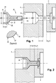
figure 1 est une vue en coupe selon un axe central du frein d'un disque arrière de frein d'aéronef au niveau de l'un des orifices recevant un rivet de fixation d'un plot en cours de solidarisation selon l'invention ; - la
figure 2 est une vue analogue à celle de lafigure 1 , montrant le plot solidarisé au disque arrière.
- the
figure 1 is a sectional view along a central axis of the brake of a rear aircraft brake disc at one of the orifices receiving a rivet for fixing a stud being secured according to the invention; - the
figure 2 is a view similar to that of thefigure 1 , showing the stud secured to the rear disc.
L'invention s'applique à la liaison entre un disque arrière 4 de frein en carbone pour aéronef et des plots 5. Par disque arrière on entend l'élément en carbone qui vient en appui via les plots contre l'extrémité du tube de torsion du frein sur lequel la pile de disques est enfilée. Il s'agit en général du dernier disque stator de la pile de disques du frein.The invention applies to the connection between a rear
Selon l'invention, chaque plot 5 est rapporté sur le disque arrière 4 selon les dispositions suivantes. Comme cela est visible à la
Pour solidariser le plot 5 au disque arrière 4, on utilise un rivet 20 qui, selon l'invention, comporte une tige 21 de diamètre légèrement inférieur à D1 pour pouvoir pénétrer à ajustement dans la première portion 11 de l'orifice 10 du disque arrière 4 et dans l'orifice 14 du plot 5. La tige 21 comporte ici une extrémité 22 creuse pour son écrasement contre le plot 5. Le rivet 5 comporte par ailleurs une tête 23 qui comprend une base conique 24 destinée à venir en appui contre l'épaulement conique 13 de l'orifice 10, surmontée par une partie circulaire cylindrique creuse 25 de diamètre extérieur D légèrement inférieur à D2 de sorte à pouvoir pénétrer à ajustement dans la deuxième portion 12 de l'orifice 10 du disque arrière 4. La partie circulaire cylindrique 25 de la tête 23 forme ainsi une jupe guidant le rivet 20 lors de sa mise en place dans l'orifice 10 et assurant que la tige 21 pénètre effectivement dans la première portion 11 dudit orifice, sans se mettre de travers.To secure the
Comme cela est visible à la
De préférence, la partie cylindrique circulaire 25 de la tête 23 a une hauteur h au moins égale à 20% du diamètre extérieur D de ladite partie. En outre, lorsque le rivet 20 est mis en place, la longueur l1 de la portion 11 de diamètre D1 de l'orifice 10 du disque arrière 4 est supérieure à la longueur l2 de l'orifice 14 du plot 5. De préférence, la longueur l1 est similaire à la longueur l2 de préférence dans une fourchette de 80% à 120% de la longueur l2. Ces dispositions diminuent encore le risque d'endommagement du carbone du disque arrière 4.Preferably, the circular
L'invention n'est pas limitée à ce qui vient d'être décrit mais englobe au contraire toute variante entrant dans le cadre défini par les revendications. En particulier, bien qu'ici la tête du rivet soit creuse pour des questions de masse, la tête du rivet pourra être pleine. Il importe cependant que la tête présente une base conique suivie d'une portion cylindrique circulaire.The invention is not limited to what has just been described but on the contrary encompasses any variant coming within the scope defined by the claims. In particular, although here the head of the rivet is hollow for reasons of mass, the head of the rivet may be full. However, it is important that the head has a conical base followed by a circular cylindrical portion.
Claims (6)
Applications Claiming Priority (1)
| Application Number | Priority Date | Filing Date | Title |
|---|---|---|---|
| FR1857775A FR3085453B1 (en) | 2018-08-29 | 2018-08-29 | REAR DISC OF A STACK OF AIRCRAFT BRAKE CARBON DISCS EQUIPPED WITH PLOTS, AND BRAKE APPLYING |
Publications (2)
| Publication Number | Publication Date |
|---|---|
| EP3617543A1 true EP3617543A1 (en) | 2020-03-04 |
| EP3617543B1 EP3617543B1 (en) | 2022-06-15 |
Family
ID=65201202
Family Applications (1)
| Application Number | Title | Priority Date | Filing Date |
|---|---|---|---|
| EP19194162.4A Active EP3617543B1 (en) | 2018-08-29 | 2019-08-28 | Rear disc of a stack of carbon brake discs of an aircraft provided with pads, and brake using same |
Country Status (4)
| Country | Link |
|---|---|
| US (1) | US11060575B2 (en) |
| EP (1) | EP3617543B1 (en) |
| CN (1) | CN110873137B (en) |
| FR (1) | FR3085453B1 (en) |
Cited By (1)
| Publication number | Priority date | Publication date | Assignee | Title |
|---|---|---|---|---|
| CN111717373A (en) * | 2020-05-15 | 2020-09-29 | 成都飞机工业(集团)有限责任公司 | Unmanned aerial vehicle undercarriage rotating shaft mounting structure and mounting method |
Families Citing this family (1)
| Publication number | Priority date | Publication date | Assignee | Title |
|---|---|---|---|---|
| CN113290196B (en) * | 2021-04-16 | 2022-07-08 | 江铃汽车股份有限公司 | Punching and riveting device and punching and riveting process |
Citations (2)
| Publication number | Priority date | Publication date | Assignee | Title |
|---|---|---|---|---|
| US4146118A (en) * | 1978-02-14 | 1979-03-27 | Zankl Robert H | Brake shoe assembly |
| US5992577A (en) * | 1996-10-31 | 1999-11-30 | Messier-Bugatti | Arrangement of carbon brake disks for an aircraft brake unit and a method of assembling disks in such an arrangement |
Family Cites Families (12)
| Publication number | Priority date | Publication date | Assignee | Title |
|---|---|---|---|---|
| SU516848A1 (en) * | 1974-08-22 | 1976-06-05 | Украинский Филиал Научно-Исследовательского Института Технологии И Организации Производства | Rivet |
| DE2822379C3 (en) * | 1978-05-23 | 1981-01-15 | Selzer Fertigungstechnik Gmbh & Co, 6349 Driedorf | Brake discs for disc brakes, in particular vehicle brakes |
| GB2234024B (en) * | 1989-07-22 | 1993-09-29 | Dunlop Ltd | Carbon composite laminated structures |
| US5494138A (en) * | 1994-10-14 | 1996-02-27 | Alliedsignal, Inc. | Aircraft brake torque transfer assembly |
| US5558186A (en) * | 1995-05-24 | 1996-09-24 | The Bfgoodrich Company | Friction disk with renewable wear faces |
| US5551534A (en) * | 1995-06-05 | 1996-09-03 | Aircraft Braking Systems Corp. | Pressure balanced brake stack |
| US5862890A (en) * | 1996-01-16 | 1999-01-26 | Mcdonnell Douglas Corporation | Restrained aircraft brake apparatus |
| US6142720A (en) * | 1998-05-15 | 2000-11-07 | Ariel Industries, Plc | Fastening incorporating a tubular rivet |
| CN201080977Y (en) * | 2007-04-05 | 2008-07-02 | 王淑敏 | Landing gear braking disc pair |
| CN202451555U (en) * | 2012-02-08 | 2012-09-26 | 无锡安士达五金有限公司 | Rivet body of non-fracture mute rivet |
| CN205745020U (en) * | 2016-06-16 | 2016-11-30 | 北京优材百慕航空器材有限公司 | A riveted structure of C/C‑SiC composite brake disc |
| US10228030B2 (en) * | 2017-05-15 | 2019-03-12 | Goodrich Corporation | Multi-disk brake assembly with travel limit pin |
-
2018
- 2018-08-29 FR FR1857775A patent/FR3085453B1/en not_active Expired - Fee Related
-
2019
- 2019-08-26 CN CN201910798873.4A patent/CN110873137B/en active Active
- 2019-08-28 EP EP19194162.4A patent/EP3617543B1/en active Active
- 2019-08-29 US US16/555,785 patent/US11060575B2/en active Active
Patent Citations (2)
| Publication number | Priority date | Publication date | Assignee | Title |
|---|---|---|---|---|
| US4146118A (en) * | 1978-02-14 | 1979-03-27 | Zankl Robert H | Brake shoe assembly |
| US5992577A (en) * | 1996-10-31 | 1999-11-30 | Messier-Bugatti | Arrangement of carbon brake disks for an aircraft brake unit and a method of assembling disks in such an arrangement |
Cited By (1)
| Publication number | Priority date | Publication date | Assignee | Title |
|---|---|---|---|---|
| CN111717373A (en) * | 2020-05-15 | 2020-09-29 | 成都飞机工业(集团)有限责任公司 | Unmanned aerial vehicle undercarriage rotating shaft mounting structure and mounting method |
Also Published As
| Publication number | Publication date |
|---|---|
| CN110873137B (en) | 2021-07-20 |
| US20200072304A1 (en) | 2020-03-05 |
| FR3085453B1 (en) | 2020-11-20 |
| FR3085453A1 (en) | 2020-03-06 |
| CN110873137A (en) | 2020-03-10 |
| EP3617543B1 (en) | 2022-06-15 |
| US11060575B2 (en) | 2021-07-13 |
Similar Documents
| Publication | Publication Date | Title |
|---|---|---|
| EP0960300B1 (en) | Device for fast connection of a tube to a rigid element with anti-extraction ring and safety seal | |
| EP0723103B1 (en) | Device for rapidly connecting a tube to a rigid element | |
| EP0299880B1 (en) | Helicoidal spring compressor | |
| EP0097545B1 (en) | Stop engageable in a boring of an apparatus | |
| EP2474463B1 (en) | Removable device for guiding a cable in a cycle frame | |
| CA3011509C (en) | Pivoting lifting ring for lifting loads | |
| EP3617543B1 (en) | Rear disc of a stack of carbon brake discs of an aircraft provided with pads, and brake using same | |
| EP0551047B1 (en) | Holding device with removable guide bush | |
| EP1423285A1 (en) | Device for mounting a sensor on a motor vehicle wheel rim and related mounting method | |
| EP3954496A1 (en) | Device for handling an axis forming a pivoting link between at least two parts | |
| EP0047697A1 (en) | Device for the tamper-proof assembly of parts, such as cattle identification marks | |
| EP3299650B1 (en) | A method for equiping the end of a thin walled tube with an axial stop that is adjustable by a threaded joint | |
| EP0754868A1 (en) | Connection for adjustably assembling two separated elements | |
| FR2658573A1 (en) | WHEEL BEARING. | |
| EP1160027B1 (en) | Expansion plier | |
| FR2735844A1 (en) | Quick-fit joint for tube connected to rigid component | |
| FR2658878A1 (en) | Quick connection device between two portions of a linkage, particularly for a motor vehicle | |
| EP1188948A1 (en) | Elastic joint of a shock absorber and shock absorber with such a joint | |
| EP2402639B1 (en) | Instant coupling insert | |
| FR3028780A1 (en) | BLIND TYPE INDENTATION DEVICE FOR IMPROVING THE FATIGUE OF A BORING | |
| FR2729736A1 (en) | Quick-fit joint for tube connected to rigid component | |
| EP0811547A1 (en) | Improvement in spring compressors | |
| FR2900698A1 (en) | ANTENNA FOR FIXING A NAIL INTENDED TO BE FIXED TO THE GROUND, IN PARTICULAR A PODOTACTILE NUT, AND TOGETHER COMPRISING THIS VHEVILLE AND THIS NAIL | |
| FR3130331A1 (en) | Versatile bolt allowing the installation of a screw nut or a crimp ring from one end only by applying a preload | |
| FR3166674A1 (en) | Added torque transmission lug braking device, wheel, landing gear and aircraft comprising it. |
Legal Events
| Date | Code | Title | Description |
|---|---|---|---|
| PUAI | Public reference made under article 153(3) epc to a published international application that has entered the european phase |
Free format text: ORIGINAL CODE: 0009012 |
|
| STAA | Information on the status of an ep patent application or granted ep patent |
Free format text: STATUS: THE APPLICATION HAS BEEN PUBLISHED |
|
| AK | Designated contracting states |
Kind code of ref document: A1 Designated state(s): AL AT BE BG CH CY CZ DE DK EE ES FI FR GB GR HR HU IE IS IT LI LT LU LV MC MK MT NL NO PL PT RO RS SE SI SK SM TR |
|
| AX | Request for extension of the european patent |
Extension state: BA ME |
|
| STAA | Information on the status of an ep patent application or granted ep patent |
Free format text: STATUS: REQUEST FOR EXAMINATION WAS MADE |
|
| 17P | Request for examination filed |
Effective date: 20200813 |
|
| RBV | Designated contracting states (corrected) |
Designated state(s): AL AT BE BG CH CY CZ DE DK EE ES FI FR GB GR HR HU IE IS IT LI LT LU LV MC MK MT NL NO PL PT RO RS SE SI SK SM TR |
|
| RIC1 | Information provided on ipc code assigned before grant |
Ipc: F16D 69/04 20060101ALI20210111BHEP Ipc: F16D 55/36 20060101AFI20210111BHEP Ipc: B21J 15/00 20060101ALI20210111BHEP |
|
| STAA | Information on the status of an ep patent application or granted ep patent |
Free format text: STATUS: EXAMINATION IS IN PROGRESS |
|
| 17Q | First examination report despatched |
Effective date: 20210401 |
|
| GRAP | Despatch of communication of intention to grant a patent |
Free format text: ORIGINAL CODE: EPIDOSNIGR1 |
|
| STAA | Information on the status of an ep patent application or granted ep patent |
Free format text: STATUS: GRANT OF PATENT IS INTENDED |
|
| INTG | Intention to grant announced |
Effective date: 20220103 |
|
| GRAS | Grant fee paid |
Free format text: ORIGINAL CODE: EPIDOSNIGR3 |
|
| GRAA | (expected) grant |
Free format text: ORIGINAL CODE: 0009210 |
|
| STAA | Information on the status of an ep patent application or granted ep patent |
Free format text: STATUS: THE PATENT HAS BEEN GRANTED |
|
| AK | Designated contracting states |
Kind code of ref document: B1 Designated state(s): AL AT BE BG CH CY CZ DE DK EE ES FI FR GB GR HR HU IE IS IT LI LT LU LV MC MK MT NL NO PL PT RO RS SE SI SK SM TR |
|
| REG | Reference to a national code |
Ref country code: CH Ref legal event code: EP Ref country code: GB Ref legal event code: FG4D Free format text: NOT ENGLISH |
|
| REG | Reference to a national code |
Ref country code: IE Ref legal event code: FG4D Free format text: LANGUAGE OF EP DOCUMENT: FRENCH |
|
| REG | Reference to a national code |
Ref country code: DE Ref legal event code: R096 Ref document number: 602019015839 Country of ref document: DE |
|
| REG | Reference to a national code |
Ref country code: AT Ref legal event code: REF Ref document number: 1498565 Country of ref document: AT Kind code of ref document: T Effective date: 20220715 |
|
| REG | Reference to a national code |
Ref country code: LT Ref legal event code: MG9D |
|
| REG | Reference to a national code |
Ref country code: NL Ref legal event code: MP Effective date: 20220615 |
|
| PG25 | Lapsed in a contracting state [announced via postgrant information from national office to epo] |
Ref country code: SE Free format text: LAPSE BECAUSE OF FAILURE TO SUBMIT A TRANSLATION OF THE DESCRIPTION OR TO PAY THE FEE WITHIN THE PRESCRIBED TIME-LIMIT Effective date: 20220615 Ref country code: NO Free format text: LAPSE BECAUSE OF FAILURE TO SUBMIT A TRANSLATION OF THE DESCRIPTION OR TO PAY THE FEE WITHIN THE PRESCRIBED TIME-LIMIT Effective date: 20220915 Ref country code: LT Free format text: LAPSE BECAUSE OF FAILURE TO SUBMIT A TRANSLATION OF THE DESCRIPTION OR TO PAY THE FEE WITHIN THE PRESCRIBED TIME-LIMIT Effective date: 20220615 Ref country code: HR Free format text: LAPSE BECAUSE OF FAILURE TO SUBMIT A TRANSLATION OF THE DESCRIPTION OR TO PAY THE FEE WITHIN THE PRESCRIBED TIME-LIMIT Effective date: 20220615 Ref country code: GR Free format text: LAPSE BECAUSE OF FAILURE TO SUBMIT A TRANSLATION OF THE DESCRIPTION OR TO PAY THE FEE WITHIN THE PRESCRIBED TIME-LIMIT Effective date: 20220916 Ref country code: FI Free format text: LAPSE BECAUSE OF FAILURE TO SUBMIT A TRANSLATION OF THE DESCRIPTION OR TO PAY THE FEE WITHIN THE PRESCRIBED TIME-LIMIT Effective date: 20220615 Ref country code: BG Free format text: LAPSE BECAUSE OF FAILURE TO SUBMIT A TRANSLATION OF THE DESCRIPTION OR TO PAY THE FEE WITHIN THE PRESCRIBED TIME-LIMIT Effective date: 20220915 |
|
| REG | Reference to a national code |
Ref country code: AT Ref legal event code: MK05 Ref document number: 1498565 Country of ref document: AT Kind code of ref document: T Effective date: 20220615 |
|
| PG25 | Lapsed in a contracting state [announced via postgrant information from national office to epo] |
Ref country code: RS Free format text: LAPSE BECAUSE OF FAILURE TO SUBMIT A TRANSLATION OF THE DESCRIPTION OR TO PAY THE FEE WITHIN THE PRESCRIBED TIME-LIMIT Effective date: 20220615 Ref country code: LV Free format text: LAPSE BECAUSE OF FAILURE TO SUBMIT A TRANSLATION OF THE DESCRIPTION OR TO PAY THE FEE WITHIN THE PRESCRIBED TIME-LIMIT Effective date: 20220615 |
|
| PG25 | Lapsed in a contracting state [announced via postgrant information from national office to epo] |
Ref country code: NL Free format text: LAPSE BECAUSE OF FAILURE TO SUBMIT A TRANSLATION OF THE DESCRIPTION OR TO PAY THE FEE WITHIN THE PRESCRIBED TIME-LIMIT Effective date: 20220615 |
|
| PG25 | Lapsed in a contracting state [announced via postgrant information from national office to epo] |
Ref country code: SM Free format text: LAPSE BECAUSE OF FAILURE TO SUBMIT A TRANSLATION OF THE DESCRIPTION OR TO PAY THE FEE WITHIN THE PRESCRIBED TIME-LIMIT Effective date: 20220615 Ref country code: SK Free format text: LAPSE BECAUSE OF FAILURE TO SUBMIT A TRANSLATION OF THE DESCRIPTION OR TO PAY THE FEE WITHIN THE PRESCRIBED TIME-LIMIT Effective date: 20220615 Ref country code: RO Free format text: LAPSE BECAUSE OF FAILURE TO SUBMIT A TRANSLATION OF THE DESCRIPTION OR TO PAY THE FEE WITHIN THE PRESCRIBED TIME-LIMIT Effective date: 20220615 Ref country code: PT Free format text: LAPSE BECAUSE OF FAILURE TO SUBMIT A TRANSLATION OF THE DESCRIPTION OR TO PAY THE FEE WITHIN THE PRESCRIBED TIME-LIMIT Effective date: 20221017 Ref country code: ES Free format text: LAPSE BECAUSE OF FAILURE TO SUBMIT A TRANSLATION OF THE DESCRIPTION OR TO PAY THE FEE WITHIN THE PRESCRIBED TIME-LIMIT Effective date: 20220615 Ref country code: EE Free format text: LAPSE BECAUSE OF FAILURE TO SUBMIT A TRANSLATION OF THE DESCRIPTION OR TO PAY THE FEE WITHIN THE PRESCRIBED TIME-LIMIT Effective date: 20220615 Ref country code: CZ Free format text: LAPSE BECAUSE OF FAILURE TO SUBMIT A TRANSLATION OF THE DESCRIPTION OR TO PAY THE FEE WITHIN THE PRESCRIBED TIME-LIMIT Effective date: 20220615 Ref country code: AT Free format text: LAPSE BECAUSE OF FAILURE TO SUBMIT A TRANSLATION OF THE DESCRIPTION OR TO PAY THE FEE WITHIN THE PRESCRIBED TIME-LIMIT Effective date: 20220615 |
|
| PG25 | Lapsed in a contracting state [announced via postgrant information from national office to epo] |
Ref country code: PL Free format text: LAPSE BECAUSE OF FAILURE TO SUBMIT A TRANSLATION OF THE DESCRIPTION OR TO PAY THE FEE WITHIN THE PRESCRIBED TIME-LIMIT Effective date: 20220615 Ref country code: IS Free format text: LAPSE BECAUSE OF FAILURE TO SUBMIT A TRANSLATION OF THE DESCRIPTION OR TO PAY THE FEE WITHIN THE PRESCRIBED TIME-LIMIT Effective date: 20221015 |
|
| REG | Reference to a national code |
Ref country code: DE Ref legal event code: R119 Ref document number: 602019015839 Country of ref document: DE |
|
| PG25 | Lapsed in a contracting state [announced via postgrant information from national office to epo] |
Ref country code: MC Free format text: LAPSE BECAUSE OF FAILURE TO SUBMIT A TRANSLATION OF THE DESCRIPTION OR TO PAY THE FEE WITHIN THE PRESCRIBED TIME-LIMIT Effective date: 20220615 Ref country code: AL Free format text: LAPSE BECAUSE OF FAILURE TO SUBMIT A TRANSLATION OF THE DESCRIPTION OR TO PAY THE FEE WITHIN THE PRESCRIBED TIME-LIMIT Effective date: 20220615 |
|
| REG | Reference to a national code |
Ref country code: CH Ref legal event code: PL |
|
| PLBE | No opposition filed within time limit |
Free format text: ORIGINAL CODE: 0009261 |
|
| STAA | Information on the status of an ep patent application or granted ep patent |
Free format text: STATUS: NO OPPOSITION FILED WITHIN TIME LIMIT |
|
| PG25 | Lapsed in a contracting state [announced via postgrant information from national office to epo] |
Ref country code: LU Free format text: LAPSE BECAUSE OF NON-PAYMENT OF DUE FEES Effective date: 20220828 Ref country code: LI Free format text: LAPSE BECAUSE OF NON-PAYMENT OF DUE FEES Effective date: 20220831 Ref country code: DK Free format text: LAPSE BECAUSE OF FAILURE TO SUBMIT A TRANSLATION OF THE DESCRIPTION OR TO PAY THE FEE WITHIN THE PRESCRIBED TIME-LIMIT Effective date: 20220615 Ref country code: CH Free format text: LAPSE BECAUSE OF NON-PAYMENT OF DUE FEES Effective date: 20220831 |
|
| REG | Reference to a national code |
Ref country code: BE Ref legal event code: MM Effective date: 20220831 |
|
| 26N | No opposition filed |
Effective date: 20230316 |
|
| PG25 | Lapsed in a contracting state [announced via postgrant information from national office to epo] |
Ref country code: SI Free format text: LAPSE BECAUSE OF FAILURE TO SUBMIT A TRANSLATION OF THE DESCRIPTION OR TO PAY THE FEE WITHIN THE PRESCRIBED TIME-LIMIT Effective date: 20220615 |
|
| PG25 | Lapsed in a contracting state [announced via postgrant information from national office to epo] |
Ref country code: IE Free format text: LAPSE BECAUSE OF NON-PAYMENT OF DUE FEES Effective date: 20220828 Ref country code: DE Free format text: LAPSE BECAUSE OF NON-PAYMENT OF DUE FEES Effective date: 20230301 |
|
| PG25 | Lapsed in a contracting state [announced via postgrant information from national office to epo] |
Ref country code: BE Free format text: LAPSE BECAUSE OF NON-PAYMENT OF DUE FEES Effective date: 20220831 |
|
| PG25 | Lapsed in a contracting state [announced via postgrant information from national office to epo] |
Ref country code: IT Free format text: LAPSE BECAUSE OF FAILURE TO SUBMIT A TRANSLATION OF THE DESCRIPTION OR TO PAY THE FEE WITHIN THE PRESCRIBED TIME-LIMIT Effective date: 20220615 |
|
| PG25 | Lapsed in a contracting state [announced via postgrant information from national office to epo] |
Ref country code: HU Free format text: LAPSE BECAUSE OF FAILURE TO SUBMIT A TRANSLATION OF THE DESCRIPTION OR TO PAY THE FEE WITHIN THE PRESCRIBED TIME-LIMIT; INVALID AB INITIO Effective date: 20190828 |
|
| PG25 | Lapsed in a contracting state [announced via postgrant information from national office to epo] |
Ref country code: CY Free format text: LAPSE BECAUSE OF FAILURE TO SUBMIT A TRANSLATION OF THE DESCRIPTION OR TO PAY THE FEE WITHIN THE PRESCRIBED TIME-LIMIT Effective date: 20220615 |
|
| PG25 | Lapsed in a contracting state [announced via postgrant information from national office to epo] |
Ref country code: MK Free format text: LAPSE BECAUSE OF FAILURE TO SUBMIT A TRANSLATION OF THE DESCRIPTION OR TO PAY THE FEE WITHIN THE PRESCRIBED TIME-LIMIT Effective date: 20220615 |
|
| PG25 | Lapsed in a contracting state [announced via postgrant information from national office to epo] |
Ref country code: MT Free format text: LAPSE BECAUSE OF FAILURE TO SUBMIT A TRANSLATION OF THE DESCRIPTION OR TO PAY THE FEE WITHIN THE PRESCRIBED TIME-LIMIT Effective date: 20220615 |
|
| PG25 | Lapsed in a contracting state [announced via postgrant information from national office to epo] |
Ref country code: BG Free format text: LAPSE BECAUSE OF FAILURE TO SUBMIT A TRANSLATION OF THE DESCRIPTION OR TO PAY THE FEE WITHIN THE PRESCRIBED TIME-LIMIT Effective date: 20220615 |
|
| PG25 | Lapsed in a contracting state [announced via postgrant information from national office to epo] |
Ref country code: BG Free format text: LAPSE BECAUSE OF FAILURE TO SUBMIT A TRANSLATION OF THE DESCRIPTION OR TO PAY THE FEE WITHIN THE PRESCRIBED TIME-LIMIT Effective date: 20220615 |
|
| PGFP | Annual fee paid to national office [announced via postgrant information from national office to epo] |
Ref country code: GB Payment date: 20250825 Year of fee payment: 7 |
|
| PGFP | Annual fee paid to national office [announced via postgrant information from national office to epo] |
Ref country code: FR Payment date: 20250821 Year of fee payment: 7 |
|
| PG25 | Lapsed in a contracting state [announced via postgrant information from national office to epo] |
Ref country code: TR Free format text: LAPSE BECAUSE OF FAILURE TO SUBMIT A TRANSLATION OF THE DESCRIPTION OR TO PAY THE FEE WITHIN THE PRESCRIBED TIME-LIMIT Effective date: 20220615 |