EP3617536B1 - Biaxial hinge mechanism used on mobile terminal and mobile terminal - Google Patents
Biaxial hinge mechanism used on mobile terminal and mobile terminal Download PDFInfo
- Publication number
- EP3617536B1 EP3617536B1 EP17907938.9A EP17907938A EP3617536B1 EP 3617536 B1 EP3617536 B1 EP 3617536B1 EP 17907938 A EP17907938 A EP 17907938A EP 3617536 B1 EP3617536 B1 EP 3617536B1
- Authority
- EP
- European Patent Office
- Prior art keywords
- shaft
- gear
- biaxial hinge
- connection end
- hinge mechanism
- Prior art date
- Legal status (The legal status is an assumption and is not a legal conclusion. Google has not performed a legal analysis and makes no representation as to the accuracy of the status listed.)
- Active
Links
Images

Classifications
-
- E—FIXED CONSTRUCTIONS
- E05—LOCKS; KEYS; WINDOW OR DOOR FITTINGS; SAFES
- E05D—HINGES OR SUSPENSION DEVICES FOR DOORS, WINDOWS OR WINGS
- E05D5/00—Construction of single parts, e.g. the parts for attachment
- E05D5/10—Pins, sockets or sleeves; Removable pins
- E05D5/12—Securing pins in sockets, movably or not
- E05D5/125—Non-removable, snap-fitted pins
-
- G—PHYSICS
- G06—COMPUTING OR CALCULATING; COUNTING
- G06F—ELECTRIC DIGITAL DATA PROCESSING
- G06F1/00—Details not covered by groups G06F3/00 - G06F13/00 and G06F21/00
- G06F1/16—Constructional details or arrangements
- G06F1/1613—Constructional details or arrangements for portable computers
- G06F1/1633—Constructional details or arrangements of portable computers not specific to the type of enclosures covered by groups G06F1/1615 - G06F1/1626
- G06F1/1675—Miscellaneous details related to the relative movement between the different enclosures or enclosure parts
- G06F1/1681—Details related solely to hinges
-
- E—FIXED CONSTRUCTIONS
- E05—LOCKS; KEYS; WINDOW OR DOOR FITTINGS; SAFES
- E05D—HINGES OR SUSPENSION DEVICES FOR DOORS, WINDOWS OR WINGS
- E05D5/00—Construction of single parts, e.g. the parts for attachment
- E05D5/10—Pins, sockets or sleeves; Removable pins
- E05D5/14—Construction of sockets or sleeves
-
- F—MECHANICAL ENGINEERING; LIGHTING; HEATING; WEAPONS; BLASTING
- F16—ENGINEERING ELEMENTS AND UNITS; GENERAL MEASURES FOR PRODUCING AND MAINTAINING EFFECTIVE FUNCTIONING OF MACHINES OR INSTALLATIONS; THERMAL INSULATION IN GENERAL
- F16C—SHAFTS; FLEXIBLE SHAFTS; ELEMENTS OR CRANKSHAFT MECHANISMS; ROTARY BODIES OTHER THAN GEARING ELEMENTS; BEARINGS
- F16C11/00—Pivots; Pivotal connections
- F16C11/04—Pivotal connections
-
- G—PHYSICS
- G06—COMPUTING OR CALCULATING; COUNTING
- G06F—ELECTRIC DIGITAL DATA PROCESSING
- G06F1/00—Details not covered by groups G06F3/00 - G06F13/00 and G06F21/00
- G06F1/16—Constructional details or arrangements
-
- G—PHYSICS
- G06—COMPUTING OR CALCULATING; COUNTING
- G06F—ELECTRIC DIGITAL DATA PROCESSING
- G06F1/00—Details not covered by groups G06F3/00 - G06F13/00 and G06F21/00
- G06F1/16—Constructional details or arrangements
- G06F1/1613—Constructional details or arrangements for portable computers
- G06F1/1615—Constructional details or arrangements for portable computers with several enclosures having relative motions, each enclosure supporting at least one I/O or computing function
- G06F1/1616—Constructional details or arrangements for portable computers with several enclosures having relative motions, each enclosure supporting at least one I/O or computing function with folding flat displays, e.g. laptop computers or notebooks having a clamshell configuration, with body parts pivoting to an open position around an axis parallel to the plane they define in closed position
Definitions
- the present invention relates to a mobile terminal and a biaxial hinge mechanism used on a mobile terminal.
- An object of the present invention is to provide a biaxial hinge mechanism used on a mobile terminal, aiding in reducing the thickness of the mobile terminal. To this end, the present invention is defined by claim 1.
- the side face is a plane
- the connection end face is a plane
- the top surface and bottom surface of the connection end are planes when the biaxial hinge mechanism is in a closed state.
- the side face is a plane
- the connection end face is a plane
- the top surface and bottom surface of the connection end are planes or concave surfaces when the biaxial hinge mechanism is in a closed state.
- a synchronization mechanism is connected between the first shaft and the second shaft.
- the synchronization mechanism comprises a first gear and a second gear respectively connected to the first shaft and the second shaft, rotation centers of the first gear and the second gear respectively coincide with rotation centers of the first shaft and the second shaft, the first gear is connected to the second gear by a transition gear pair composed of a third gear and a fourth gear, the number of teeth and diameter of the first gear are the same as the second gear, and the number of teeth and diameter of the third gear are the same as the fourth gear.
- the first gear and the second gear are respectively sleeved outside the first shaft and the second shaft.
- the biaxial hinge mechanism is further provided with a torsion member, and a first reed pipe and a second reed pipe are respectively provided on the upper and lower portions of the torsion member, the first reed pipe and the second reed pipe are respectively sleeved on the first shaft and the second shaft, and frictionally engaged with the first shaft and the second shaft respectively.
- a mobile terminal comprising a body and a cover, wherein the mobile terminal is provided with any one of the foregoing biaxial hinge mechanisms, and the first support and the second support are respectively connected to the body and the cover of the mobile terminal.
- the spaces of the side faces of the hinge are fully used to connect the supports, providing a high space utilization rate and aiding in greatly reducing the thickness of the hinge, and the used connection structure facilitates installation of the supports on the side faces of the hinge, providing a high connection strength.
- a relatively large rotating torque can be realized by the relatively small size, for example, the torque can reach over 3.5 kg/cm with the overall outer diameter within 3.3 mm.
- a biaxial hinge mechanism used on a mobile terminal comprising a first shaft 11 and a second shaft 12 parallel to each other, and a first support 21 and a second support 22, wherein the first support 21 and second support 22 are respectively connected to the connection ends 31, 32 of the first shaft 11 and second shaft 12, the first support 21 and second support 22 are provided with portions for connecting with two relatively rotating components on the mobile terminal, and the portion may be a connection hole 4.
- the first support 21 is provided with a connection end face 211 facing side face 311 of connection end of the first shaft, a first riveting column 51 formed in an integrated manner with the first support 21 by powder metallurgy die casting technology is provided on the connection end face 211 of the first support, the first shaft connection end 31 is provided with a first connection through hole 61 on the side face of the first shaft connection end 311; the first riveting column 51 is connected to the first connection through hole 61; the second support 22 is provided with a connection end face 221 facing side face 321 of connection end of the second shaft, a second riveting column 52 formed in an integrated manner with the second support 22 by powder metallurgy die casting technology is provided on the connection end face 221 of the second support, the second shaft connection end 32 is provided with a second connection through hole 62 on the side face of the second shaft connection end 321, the second riveting column 52 is connected to the second connection through hole 62; the side faces 311, 321 are the faces the connection end faces 211, 221 of the first shaft and second
- connection ends are provided with grooves 315, 325 around an opening of the other end of the connection through hole on another side face 312, 322 with respect to the side surface, and the grooves are provided with flat bottom surfaces.
- the side faces 311, 321 are planes
- the connection end faces 211, 221 are planes
- the top surfaces 313, 323 and the bottom surfaces 314, 324 of the connection ends 31, 32 are planes when the biaxial hinge mechanism is in a closed state.
- a synchronization mechanism is connected between the first shaft 11 and the second shaft 12, to enable them to achieve simultaneous reverse rotation.
- the synchronization mechanism can adopt a variety of structures such as a cam, a gear, and a spiral, etc.
- the synchronization mechanism of the present embodiment comprises a first gear 71 and a second gear 72 respectively connected to the first shaft 11 and the second shaft 12, rotation centers of the first gear 71 and the second gear 72 respectively coincide with rotation centers of the first shaft 11 and the second shaft 12, the first gear 71 and the second gear 72 are respectively sleeved outside the first shaft 11 and the second shaft 12, the first gear 71 is connected to the second gear 72 by a transition gear pair composed of a third gear 73 and a fourth gear 74, the number of teeth and diameter of the first gear 71 are the same as the second gear 72, and the number of teeth and diameter of the third gear 73 are the same as the fourth gear 74.
- the biaxial hinge mechanism is further provided with a torsion member 8, and a first reed pipe 81 and a second reed pipe 82 are respectively provided on the upper and lower portions of the torsion member, the first reed pipe 81 and the second reed pipe 82 are respectively sleeved on the first shaft 11 and the second shaft 12, and frictionally engaged with the first shaft 11 and the second shaft 12 respectively, to achieve instant positioning when stopped at any time as necessary during the rotation of the hinge.
- a mobile terminal comprises a body 902 and a cover 901, the body 902 is connected to the cover 901 by the foregoing biaxial hinge mechanism 900, the first support is connected to the cover 101, and the second support 22 is connected to the body 102.
Landscapes
- Engineering & Computer Science (AREA)
- General Engineering & Computer Science (AREA)
- Theoretical Computer Science (AREA)
- Computer Hardware Design (AREA)
- Physics & Mathematics (AREA)
- Mechanical Engineering (AREA)
- Human Computer Interaction (AREA)
- General Physics & Mathematics (AREA)
- Mathematical Physics (AREA)
- Pivots And Pivotal Connections (AREA)
- Telephone Set Structure (AREA)
- Casings For Electric Apparatus (AREA)
Description
- The present invention relates to a mobile terminal and a biaxial hinge mechanism used on a mobile terminal.
- At present, there are increasingly high requirement for the thickness of portable electronic products such as notebook computers. For a biaxial hinge, as described by
US 2015/362958 , due to its complicated structure, it is more difficult to reduce the thickness under the premise of guaranteeing its original performance. - An object of the present invention is to provide a biaxial hinge mechanism used on a mobile terminal, aiding in reducing the thickness of the mobile terminal. To this end, the present invention is defined by claim 1.
- In an embodiment, the side face is a plane, and the connection end face is a plane.
- In an embodiment, the top surface and bottom surface of the connection end are planes when the biaxial hinge mechanism is in a closed state.
- In an embodiment, the side face is a plane, the connection end face is a plane; the top surface and bottom surface of the connection end are planes or concave surfaces when the biaxial hinge mechanism is in a closed state.
- In an embodiment, a synchronization mechanism is connected between the first shaft and the second shaft.
- The synchronization mechanism comprises a first gear and a second gear respectively connected to the first shaft and the second shaft, rotation centers of the first gear and the second gear respectively coincide with rotation centers of the first shaft and the second shaft, the first gear is connected to the second gear by a transition gear pair composed of a third gear and a fourth gear, the number of teeth and diameter of the first gear are the same as the second gear, and the number of teeth and diameter of the third gear are the same as the fourth gear.
- The first gear and the second gear are respectively sleeved outside the first shaft and the second shaft.
- The biaxial hinge mechanism is further provided with a torsion member, and a first reed pipe and a second reed pipe are respectively provided on the upper and lower portions of the torsion member, the first reed pipe and the second reed pipe are respectively sleeved on the first shaft and the second shaft, and frictionally engaged with the first shaft and the second shaft respectively.
- Another object of the present invention is to provide a portable electronic product using the foregoing biaxial hinge mechanism. To this end, the invention adopts the following technical solutions:
A mobile terminal, comprising a body and a cover, wherein the mobile terminal is provided with any one of the foregoing biaxial hinge mechanisms, and the first support and the second support are respectively connected to the body and the cover of the mobile terminal. - According to the above technical solutions of the present invention, the spaces of the side faces of the hinge, rather than the spaces in the thickness direction of the hinge, are fully used to connect the supports, providing a high space utilization rate and aiding in greatly reducing the thickness of the hinge, and the used connection structure facilitates installation of the supports on the side faces of the hinge, providing a high connection strength. A relatively large rotating torque can be realized by the relatively small size, for example, the torque can reach over 3.5 kg/cm with the overall outer diameter within 3.3 mm.
-
-
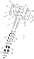
FIG. 1 is an exploded view of a biaxial hinge mechanism according to an embodiment of the invention. -
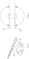
FIG. 2 is a schematic view showing the installation of a support of the invention. -
FIG. 3 is a schematic view showing the rotation, opening and closing of a biaxial hinge mechanism of the invention. -
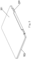
FIG. 4 is a demonstration view showing the opening process of a biaxial hinge mechanism of the invention. -
FIG. 5 is a schematic view of a mobile terminal to which a biaxial hinge mechanism of the invention is applied. - Referring to the figures, a biaxial hinge mechanism used on a mobile terminal provided herein, comprising a
first shaft 11 and a second shaft 12 parallel to each other, and afirst support 21 and asecond support 22, wherein thefirst support 21 andsecond support 22 are respectively connected to the connection ends 31, 32 of thefirst shaft 11 and second shaft 12, thefirst support 21 andsecond support 22 are provided with portions for connecting with two relatively rotating components on the mobile terminal, and the portion may be aconnection hole 4. - The
first support 21 is provided with aconnection end face 211 facingside face 311 of connection end of the first shaft, a first rivetingcolumn 51 formed in an integrated manner with thefirst support 21 by powder metallurgy die casting technology is provided on theconnection end face 211 of the first support, the firstshaft connection end 31 is provided with a first connection throughhole 61 on the side face of the firstshaft connection end 311; the first rivetingcolumn 51 is connected to the first connection throughhole 61; thesecond support 22 is provided with aconnection end face 221 facingside face 321 of connection end of the second shaft, a second rivetingcolumn 52 formed in an integrated manner with thesecond support 22 by powder metallurgy die casting technology is provided on theconnection end face 221 of the second support, the second shaft connection end 32 is provided with a second connection throughhole 62 on the side face of the secondshaft connection end 321, the second rivetingcolumn 52 is connected to the second connection throughhole 62; the side faces 311, 321 are the faces theconnection end faces - In order to further reduce the thickness and maintain sufficient strength, the connection ends are provided with
grooves side face
In order to further reduce the thickness, the side faces 311, 321 are planes, theconnection end faces top surfaces bottom surfaces - A synchronization mechanism is connected between the
first shaft 11 and the second shaft 12, to enable them to achieve simultaneous reverse rotation. - The synchronization mechanism can adopt a variety of structures such as a cam, a gear, and a spiral, etc. The synchronization mechanism of the present embodiment comprises a
first gear 71 and asecond gear 72 respectively connected to thefirst shaft 11 and the second shaft 12, rotation centers of thefirst gear 71 and thesecond gear 72 respectively coincide with rotation centers of thefirst shaft 11 and the second shaft 12, thefirst gear 71 and thesecond gear 72 are respectively sleeved outside thefirst shaft 11 and the second shaft 12, thefirst gear 71 is connected to thesecond gear 72 by a transition gear pair composed of athird gear 73 and afourth gear 74, the number of teeth and diameter of thefirst gear 71 are the same as thesecond gear 72, and the number of teeth and diameter of thethird gear 73 are the same as thefourth gear 74. - The biaxial hinge mechanism is further provided with a
torsion member 8, and afirst reed pipe 81 and asecond reed pipe 82 are respectively provided on the upper and lower portions of the torsion member, thefirst reed pipe 81 and thesecond reed pipe 82 are respectively sleeved on thefirst shaft 11 and the second shaft 12, and frictionally engaged with thefirst shaft 11 and the second shaft 12 respectively, to achieve instant positioning when stopped at any time as necessary during the rotation of the hinge. - In the present embodiment, taking a notebook computer as an example, a mobile terminal comprises a
body 902 and acover 901, thebody 902 is connected to thecover 901 by the foregoingbiaxial hinge mechanism 900, the first support is connected to the cover 101, and thesecond support 22 is connected to the body 102.
Claims (9)
- A biaxial hinge mechanism for a mobile terminal, wherein the hinge mechanism comprises:a first shaft (11) and a second shaft (12) parallel to each other, anda first support (21) and a second support (22),wherein the first and second supports (21, 22) are:respectively connected to connection ends (31, 32) of the first and second shafts (21, 22), andconnection holes (4) for connecting with two relatively rotating components on the mobile terminal,wherein:the first support (21) is provided with:a connection end face (211) facing a side face (311) of the connection end (31) of the first shaft (11),a first riveting column (51) formed in an integrated manner with the first support (21) and provided on the connection end face (211) of the first support (21),the connection end (31) of the first shaft (11) is provided with a first connection through hole (61) on the side face (311) of the connection end (31) of the first shaft (11),the first riveting column (51) is connected to the first connection through hole (61);the second support (22) is provided with:a connection end face (221) facing a side face (321) of the connection end (31) of the second shaft (12), anda second riveting column (52) formed in an integrated manner with the second support (22) and provided on the connection end face (221) of the second support (21),the connection end (32) of the second shaft (12) is provided with a second connection through hole (62) on the side face (321) of the connection end (32) of the second shaft (12),the second riveting column (52) is connected to the second connection through hole (62),the side face is the face the connection end faces of the first and second shafts face to when the biaxial hinge mechanism is in a closed state, andcharacterized in thatthe connection ends (31, 32) are provided with grooves (315, 325) around an opening of the other end of the connection through holes (61, 62) on another side face with respect to the side surface, and the grooves (315, 325) are provided with plane bottom surfaces, respectively.
- The biaxial hinge mechanism used on a mobile terminal according to claim 1, wherein the side face is a plane, and the connection end face is a plane.
- The biaxial hinge mechanism used on a mobile terminal according to claim 2, wherein the top surface and bottom surface of the connection end are planes when the biaxial hinge mechanism is in a closed state.
- The biaxial hinge mechanism used on a mobile terminal according to claim 1, wherein the side face is a plane, the connection end face is a plane; the top surface and bottom surface of the connection end are planes or concave surfaces when the biaxial hinge mechanism is in a closed state.
- The biaxial hinge mechanism according to claim 1, wherein a synchronization mechanism is connected between the first shaft (11) and the second shaft (12).
- The biaxial hinge mechanism according to claim 1, wherein the synchronization mechanism comprises a first gear (71) and a second gear (72) respectively connected to the first shaft (11) and the second shaft (12), rotation centers of the first gear (71) and the second gear (72) respectively coincide with rotation centers of the first shaft (11) and the second shaft (12), the first gear (71) is connected to the second gear (72) by a transition gear pair composed of a third gear (73) and a fourth gear (74), a number of teeth and diameter of the first gear (71) are the same as for the second gear (72), and a number of teeth and diameter of the third gear (73) are the same as for the fourth gear (74).
- The biaxial hinge mechanism used on a mobile terminal according to claim 6, wherein the first gear (71) and the second gear (72) are respectively sleeved outside the first shaft (11) and the second shaft (12).
- The biaxial hinge mechanism according to claim 1, wherein the biaxial hinge mechanism is further provided with a torsion member (8), and a first reed pipe (81) and a second reed pipe (82) are respectively provided on upper and lower portions of the torsion member, the first reed pipe (81) and the second reed pipe (82) are respectively sleeved on the first shaft (11) and the second shaft (12), and frictionally engaged with the first shaft (11) and the second shaft (12), respectively.
- A mobile terminal, comprising:a body (902),a cover (901), anda biaxial hinge mechanisms according to any one of the preceding claims,wherein the first support (21) and the second support (22) of the biaxial hinge mechanisms are respectively connected to the body (902) and the cover (901) of the mobile terminal.
Applications Claiming Priority (2)
| Application Number | Priority Date | Filing Date | Title |
|---|---|---|---|
| CN201720458186.4U CN207005077U (en) | 2017-04-27 | 2017-04-27 | The two-shaft hinge mechanism and mobile terminal applied on mobile terminal |
| PCT/CN2017/103322 WO2018196275A1 (en) | 2017-04-27 | 2017-09-26 | Biaxial hinge mechanism used on mobile terminal and mobile terminal |
Publications (3)
| Publication Number | Publication Date |
|---|---|
| EP3617536A1 EP3617536A1 (en) | 2020-03-04 |
| EP3617536A4 EP3617536A4 (en) | 2021-01-20 |
| EP3617536B1 true EP3617536B1 (en) | 2023-12-20 |
Family
ID=61443229
Family Applications (1)
| Application Number | Title | Priority Date | Filing Date |
|---|---|---|---|
| EP17907938.9A Active EP3617536B1 (en) | 2017-04-27 | 2017-09-26 | Biaxial hinge mechanism used on mobile terminal and mobile terminal |
Country Status (5)
| Country | Link |
|---|---|
| US (1) | US11555341B2 (en) |
| EP (1) | EP3617536B1 (en) |
| JP (1) | JP6836665B2 (en) |
| CN (1) | CN207005077U (en) |
| WO (1) | WO2018196275A1 (en) |
Families Citing this family (5)
| Publication number | Priority date | Publication date | Assignee | Title |
|---|---|---|---|---|
| CN112888867B (en) * | 2018-12-28 | 2023-04-18 | 三菱制钢株式会社 | Hinge and electronic equipment |
| CN210178745U (en) * | 2019-01-15 | 2020-03-24 | 杭州安费诺飞凤通信部品有限公司 | Synchronous mechanism of hinge of inward-folding flexible screen mobile terminal |
| TWI717229B (en) * | 2020-03-11 | 2021-01-21 | 和碩聯合科技股份有限公司 | Laptop computer chassis and laptop computer |
| TWI769560B (en) * | 2020-10-19 | 2022-07-01 | 華碩電腦股份有限公司 | Electronic device |
| CN113464544B (en) * | 2021-07-23 | 2022-11-18 | 新连刚电子科技(重庆)有限公司 | Simple coated gear double-shaft mechanism |
Family Cites Families (27)
| Publication number | Priority date | Publication date | Assignee | Title |
|---|---|---|---|---|
| CN202971543U (en) * | 2012-11-09 | 2013-06-05 | 昆山万禾精密电子有限公司 | Double-shaft hinge capable of being opened and closed smoothly |
| TWI547651B (en) * | 2013-06-05 | 2016-09-01 | 緯創資通股份有限公司 | Biaxial pivoting mechanism and portable electronic device thereof |
| US9182790B2 (en) * | 2013-10-15 | 2015-11-10 | Shin Zu Shing Co., Ltd. | Phase-locked pivot assembly |
| CN203548549U (en) * | 2013-11-05 | 2014-04-16 | 昆山万禾精密电子有限公司 | Synchronous rotation type double-shaft hinge |
| CN104613085A (en) * | 2013-11-05 | 2015-05-13 | 昆山万禾精密电子有限公司 | Synchronous rotary biaxial hinge |
| TWM474324U (en) * | 2013-11-25 | 2014-03-11 | Lian Hong Art Co Ltd | Synchronous mechanism torque of biaxial hinge connector |
| US9127490B2 (en) * | 2013-12-05 | 2015-09-08 | Lianhong Art Co., Ltd. | Transmission mechanism for dual-shaft hinge |
| CN104791369B (en) | 2014-01-16 | 2017-08-25 | 昆山玮硕恒基智能科技股份有限公司 | 360 degree of Biaxial synchronous Damping rotation shafts of Helical gear Transmission formula |
| CN203796732U (en) | 2014-03-03 | 2014-08-27 | 杭州安费诺飞凤通信部品有限公司 | Synchronous double-shaft hinge mechanism applied to portable electronic product and portable electronic product |
| CN203796733U (en) * | 2014-03-06 | 2014-08-27 | 杭州安费诺飞凤通信部品有限公司 | Double-shaft hinge mechanism applied to portable type electronic product and portable type electronic product |
| JP6505977B2 (en) | 2014-03-28 | 2019-04-24 | スタッフ株式会社 | Twin hinge device |
| US9265167B2 (en) * | 2014-05-09 | 2016-02-16 | First Dome Corporation | Torque balancing device applied to synchronous dual-shaft system |
| CN203948431U (en) * | 2014-05-15 | 2014-11-19 | 连鋐科技股份有限公司 | Transmission mechanism of double-shaft simultaneous-action torsion pivoting device |
| CN105202010A (en) * | 2014-06-12 | 2015-12-30 | 加藤电机(香港)有限公司 | Double-shaft hinge and terminal machine using same |
| TWI644608B (en) * | 2014-07-14 | 2018-12-11 | 富世達股份有限公司 | Double shaft synchronous transmission |
| JP2016110588A (en) | 2014-12-10 | 2016-06-20 | レノボ・シンガポール・プライベート・リミテッド | Hinge mechanism and electronic apparatus |
| CN105889308B (en) * | 2015-01-26 | 2019-01-15 | 联想(北京)有限公司 | Connector and electronic device with connector |
| TWM521869U (en) * | 2015-11-30 | 2016-05-11 | 連鋐科技股份有限公司 | Interlaced shaft integrated two-axis synchronous pivot |
| CN205744871U (en) * | 2016-03-21 | 2016-11-30 | 杭州安费诺飞凤通信部品有限公司 | Apply to the two-shaft hinge mechanism on mobile terminal and mobile terminal |
| CN107228119B (en) * | 2016-03-25 | 2020-02-28 | 加藤电机(香港)有限公司 | Biaxial hinge and terminal machine using the same |
| CN205744872U (en) * | 2016-05-04 | 2016-11-30 | 杭州安费诺飞凤通信部品有限公司 | The two-shaft hinge mechanism on mobile terminal and mobile terminal can be used for |
| JP6797393B2 (en) * | 2016-06-02 | 2020-12-09 | 株式会社ナチュラレーザ・ワン | 2-axis hinge and terminal equipment using this 2-axis hinge |
| TWM535932U (en) * | 2016-07-07 | 2017-01-21 | First Dome Corp | Torque module capable of being combined with pivot device |
| CN205937447U (en) | 2016-08-11 | 2017-02-08 | 深圳市斯蒙奇科技有限公司 | 360 degree split type rotatory pivot mechanisms |
| TWI688323B (en) * | 2017-11-22 | 2020-03-11 | 仁寶電腦工業股份有限公司 | Dual axes hinge and electronic device |
| TWI727294B (en) * | 2018-04-13 | 2021-05-11 | 仁寶電腦工業股份有限公司 | Hinge module and electronic device |
| CN216382215U (en) * | 2021-06-15 | 2022-04-26 | 杭州安费诺飞凤通信部品有限公司 | Double-shaft hinge of mobile electronic terminal |
-
2017
- 2017-04-27 CN CN201720458186.4U patent/CN207005077U/en active Active
- 2017-09-26 EP EP17907938.9A patent/EP3617536B1/en active Active
- 2017-09-26 US US16/608,426 patent/US11555341B2/en active Active
- 2017-09-26 JP JP2019558451A patent/JP6836665B2/en active Active
- 2017-09-26 WO PCT/CN2017/103322 patent/WO2018196275A1/en not_active Ceased
Also Published As
| Publication number | Publication date |
|---|---|
| EP3617536A4 (en) | 2021-01-20 |
| JP6836665B2 (en) | 2021-03-03 |
| WO2018196275A1 (en) | 2018-11-01 |
| EP3617536A1 (en) | 2020-03-04 |
| US20200141167A1 (en) | 2020-05-07 |
| US11555341B2 (en) | 2023-01-17 |
| JP2020517876A (en) | 2020-06-18 |
| CN207005077U (en) | 2018-02-13 |
Similar Documents
| Publication | Publication Date | Title |
|---|---|---|
| EP3617536B1 (en) | Biaxial hinge mechanism used on mobile terminal and mobile terminal | |
| US8959716B2 (en) | Double-shaft type rotary shaft pivotal positioning structure | |
| US9127490B2 (en) | Transmission mechanism for dual-shaft hinge | |
| KR101937557B1 (en) | Biaxial hinge and terminal device using the same | |
| US9206633B1 (en) | Hinge structure | |
| US10175730B2 (en) | Hinge module and electronic device | |
| CN105179459A (en) | Biaxial hinge and terminal machine using the biaxial hinge | |
| US9727093B2 (en) | Biaxial synchronization dual-shaft hinge | |
| CN206539598U (en) | Synchronous rotating mechanism, turnover tablet personal computer and turnover mobile phone | |
| JP2009264460A (en) | Two-shaft hinge device, and portable terminal device | |
| US20080263826A1 (en) | Hinge device | |
| US12603951B2 (en) | Rotating mechanism and foldable terminal | |
| US20140001941A1 (en) | Hinge mechanism and clamshell device thereof | |
| JP2015158267A (en) | Biaxial hinge | |
| CN205260601U (en) | Mobile terminal's novel two -axis hinge and mobile terminal | |
| CN203670439U (en) | Double-shaft hinge mechanism applied to portable electronic product and portable electronic product | |
| US20180059737A1 (en) | Hinge structure and electronic device | |
| CN209908978U (en) | Dual axis hinges and portable electronic devices | |
| CN203560287U (en) | Biaxial Torsion Pivot Flip Control Mechanism | |
| CN205089792U (en) | Synchronous damping pivot of four gear drive type 360 degree biaxs | |
| CN205446372U (en) | Mobile electron terminal two -axis hinge and mobile electron terminal | |
| TWM513284U (en) | Integrated biaxial tracking pivot device | |
| CN118274018A (en) | Folding hinges and terminal equipment | |
| US10635139B2 (en) | Connecting apparatus, rotating shaft and electronic device | |
| CN209908977U (en) | Double-shaft hinge and portable electronic equipment |
Legal Events
| Date | Code | Title | Description |
|---|---|---|---|
| STAA | Information on the status of an ep patent application or granted ep patent |
Free format text: STATUS: THE INTERNATIONAL PUBLICATION HAS BEEN MADE |
|
| PUAI | Public reference made under article 153(3) epc to a published international application that has entered the european phase |
Free format text: ORIGINAL CODE: 0009012 |
|
| STAA | Information on the status of an ep patent application or granted ep patent |
Free format text: STATUS: REQUEST FOR EXAMINATION WAS MADE |
|
| 17P | Request for examination filed |
Effective date: 20191010 |
|
| AK | Designated contracting states |
Kind code of ref document: A1 Designated state(s): AL AT BE BG CH CY CZ DE DK EE ES FI FR GB GR HR HU IE IS IT LI LT LU LV MC MK MT NL NO PL PT RO RS SE SI SK SM TR |
|
| AX | Request for extension of the european patent |
Extension state: BA ME |
|
| DAV | Request for validation of the european patent (deleted) | ||
| DAX | Request for extension of the european patent (deleted) | ||
| A4 | Supplementary search report drawn up and despatched |
Effective date: 20201221 |
|
| RIC1 | Information provided on ipc code assigned before grant |
Ipc: G06F 1/16 20060101ALI20201215BHEP Ipc: F16C 11/04 20060101AFI20201215BHEP |
|
| STAA | Information on the status of an ep patent application or granted ep patent |
Free format text: STATUS: EXAMINATION IS IN PROGRESS |
|
| 17Q | First examination report despatched |
Effective date: 20210726 |
|
| GRAP | Despatch of communication of intention to grant a patent |
Free format text: ORIGINAL CODE: EPIDOSNIGR1 |
|
| STAA | Information on the status of an ep patent application or granted ep patent |
Free format text: STATUS: GRANT OF PATENT IS INTENDED |
|
| INTG | Intention to grant announced |
Effective date: 20230713 |
|
| GRAS | Grant fee paid |
Free format text: ORIGINAL CODE: EPIDOSNIGR3 |
|
| GRAA | (expected) grant |
Free format text: ORIGINAL CODE: 0009210 |
|
| STAA | Information on the status of an ep patent application or granted ep patent |
Free format text: STATUS: THE PATENT HAS BEEN GRANTED |
|
| AK | Designated contracting states |
Kind code of ref document: B1 Designated state(s): AL AT BE BG CH CY CZ DE DK EE ES FI FR GB GR HR HU IE IS IT LI LT LU LV MC MK MT NL NO PL PT RO RS SE SI SK SM TR |
|
| REG | Reference to a national code |
Ref country code: GB Ref legal event code: FG4D |
|
| REG | Reference to a national code |
Ref country code: CH Ref legal event code: EP |
|
| REG | Reference to a national code |
Ref country code: DE Ref legal event code: R096 Ref document number: 602017077807 Country of ref document: DE |
|
| REG | Reference to a national code |
Ref country code: IE Ref legal event code: FG4D |
|
| PG25 | Lapsed in a contracting state [announced via postgrant information from national office to epo] |
Ref country code: GR Free format text: LAPSE BECAUSE OF FAILURE TO SUBMIT A TRANSLATION OF THE DESCRIPTION OR TO PAY THE FEE WITHIN THE PRESCRIBED TIME-LIMIT Effective date: 20240321 |
|
| REG | Reference to a national code |
Ref country code: LT Ref legal event code: MG9D |
|
| PG25 | Lapsed in a contracting state [announced via postgrant information from national office to epo] |
Ref country code: LT Free format text: LAPSE BECAUSE OF FAILURE TO SUBMIT A TRANSLATION OF THE DESCRIPTION OR TO PAY THE FEE WITHIN THE PRESCRIBED TIME-LIMIT Effective date: 20231220 |
|
| REG | Reference to a national code |
Ref country code: NL Ref legal event code: MP Effective date: 20231220 |
|
| PG25 | Lapsed in a contracting state [announced via postgrant information from national office to epo] |
Ref country code: ES Free format text: LAPSE BECAUSE OF FAILURE TO SUBMIT A TRANSLATION OF THE DESCRIPTION OR TO PAY THE FEE WITHIN THE PRESCRIBED TIME-LIMIT Effective date: 20231220 |
|
| PG25 | Lapsed in a contracting state [announced via postgrant information from national office to epo] |
Ref country code: LT Free format text: LAPSE BECAUSE OF FAILURE TO SUBMIT A TRANSLATION OF THE DESCRIPTION OR TO PAY THE FEE WITHIN THE PRESCRIBED TIME-LIMIT Effective date: 20231220 Ref country code: GR Free format text: LAPSE BECAUSE OF FAILURE TO SUBMIT A TRANSLATION OF THE DESCRIPTION OR TO PAY THE FEE WITHIN THE PRESCRIBED TIME-LIMIT Effective date: 20240321 Ref country code: FI Free format text: LAPSE BECAUSE OF FAILURE TO SUBMIT A TRANSLATION OF THE DESCRIPTION OR TO PAY THE FEE WITHIN THE PRESCRIBED TIME-LIMIT Effective date: 20231220 Ref country code: ES Free format text: LAPSE BECAUSE OF FAILURE TO SUBMIT A TRANSLATION OF THE DESCRIPTION OR TO PAY THE FEE WITHIN THE PRESCRIBED TIME-LIMIT Effective date: 20231220 Ref country code: BG Free format text: LAPSE BECAUSE OF FAILURE TO SUBMIT A TRANSLATION OF THE DESCRIPTION OR TO PAY THE FEE WITHIN THE PRESCRIBED TIME-LIMIT Effective date: 20240320 |
|
| REG | Reference to a national code |
Ref country code: AT Ref legal event code: MK05 Ref document number: 1642686 Country of ref document: AT Kind code of ref document: T Effective date: 20231220 |
|
| PG25 | Lapsed in a contracting state [announced via postgrant information from national office to epo] |
Ref country code: NL Free format text: LAPSE BECAUSE OF FAILURE TO SUBMIT A TRANSLATION OF THE DESCRIPTION OR TO PAY THE FEE WITHIN THE PRESCRIBED TIME-LIMIT Effective date: 20231220 |
|
| PG25 | Lapsed in a contracting state [announced via postgrant information from national office to epo] |
Ref country code: SE Free format text: LAPSE BECAUSE OF FAILURE TO SUBMIT A TRANSLATION OF THE DESCRIPTION OR TO PAY THE FEE WITHIN THE PRESCRIBED TIME-LIMIT Effective date: 20231220 Ref country code: RS Free format text: LAPSE BECAUSE OF FAILURE TO SUBMIT A TRANSLATION OF THE DESCRIPTION OR TO PAY THE FEE WITHIN THE PRESCRIBED TIME-LIMIT Effective date: 20231220 Ref country code: NO Free format text: LAPSE BECAUSE OF FAILURE TO SUBMIT A TRANSLATION OF THE DESCRIPTION OR TO PAY THE FEE WITHIN THE PRESCRIBED TIME-LIMIT Effective date: 20240320 Ref country code: NL Free format text: LAPSE BECAUSE OF FAILURE TO SUBMIT A TRANSLATION OF THE DESCRIPTION OR TO PAY THE FEE WITHIN THE PRESCRIBED TIME-LIMIT Effective date: 20231220 Ref country code: LV Free format text: LAPSE BECAUSE OF FAILURE TO SUBMIT A TRANSLATION OF THE DESCRIPTION OR TO PAY THE FEE WITHIN THE PRESCRIBED TIME-LIMIT Effective date: 20231220 Ref country code: HR Free format text: LAPSE BECAUSE OF FAILURE TO SUBMIT A TRANSLATION OF THE DESCRIPTION OR TO PAY THE FEE WITHIN THE PRESCRIBED TIME-LIMIT Effective date: 20231220 |
|
| PG25 | Lapsed in a contracting state [announced via postgrant information from national office to epo] |
Ref country code: IS Free format text: LAPSE BECAUSE OF FAILURE TO SUBMIT A TRANSLATION OF THE DESCRIPTION OR TO PAY THE FEE WITHIN THE PRESCRIBED TIME-LIMIT Effective date: 20240420 |
|
| PG25 | Lapsed in a contracting state [announced via postgrant information from national office to epo] |
Ref country code: AT Free format text: LAPSE BECAUSE OF FAILURE TO SUBMIT A TRANSLATION OF THE DESCRIPTION OR TO PAY THE FEE WITHIN THE PRESCRIBED TIME-LIMIT Effective date: 20231220 Ref country code: CZ Free format text: LAPSE BECAUSE OF FAILURE TO SUBMIT A TRANSLATION OF THE DESCRIPTION OR TO PAY THE FEE WITHIN THE PRESCRIBED TIME-LIMIT Effective date: 20231220 |
|
| PG25 | Lapsed in a contracting state [announced via postgrant information from national office to epo] |
Ref country code: SK Free format text: LAPSE BECAUSE OF FAILURE TO SUBMIT A TRANSLATION OF THE DESCRIPTION OR TO PAY THE FEE WITHIN THE PRESCRIBED TIME-LIMIT Effective date: 20231220 |
|
| PG25 | Lapsed in a contracting state [announced via postgrant information from national office to epo] |
Ref country code: SM Free format text: LAPSE BECAUSE OF FAILURE TO SUBMIT A TRANSLATION OF THE DESCRIPTION OR TO PAY THE FEE WITHIN THE PRESCRIBED TIME-LIMIT Effective date: 20231220 Ref country code: SK Free format text: LAPSE BECAUSE OF FAILURE TO SUBMIT A TRANSLATION OF THE DESCRIPTION OR TO PAY THE FEE WITHIN THE PRESCRIBED TIME-LIMIT Effective date: 20231220 Ref country code: RO Free format text: LAPSE BECAUSE OF FAILURE TO SUBMIT A TRANSLATION OF THE DESCRIPTION OR TO PAY THE FEE WITHIN THE PRESCRIBED TIME-LIMIT Effective date: 20231220 Ref country code: IT Free format text: LAPSE BECAUSE OF FAILURE TO SUBMIT A TRANSLATION OF THE DESCRIPTION OR TO PAY THE FEE WITHIN THE PRESCRIBED TIME-LIMIT Effective date: 20231220 Ref country code: IS Free format text: LAPSE BECAUSE OF FAILURE TO SUBMIT A TRANSLATION OF THE DESCRIPTION OR TO PAY THE FEE WITHIN THE PRESCRIBED TIME-LIMIT Effective date: 20240420 Ref country code: EE Free format text: LAPSE BECAUSE OF FAILURE TO SUBMIT A TRANSLATION OF THE DESCRIPTION OR TO PAY THE FEE WITHIN THE PRESCRIBED TIME-LIMIT Effective date: 20231220 Ref country code: CZ Free format text: LAPSE BECAUSE OF FAILURE TO SUBMIT A TRANSLATION OF THE DESCRIPTION OR TO PAY THE FEE WITHIN THE PRESCRIBED TIME-LIMIT Effective date: 20231220 Ref country code: AT Free format text: LAPSE BECAUSE OF FAILURE TO SUBMIT A TRANSLATION OF THE DESCRIPTION OR TO PAY THE FEE WITHIN THE PRESCRIBED TIME-LIMIT Effective date: 20231220 |
|
| PG25 | Lapsed in a contracting state [announced via postgrant information from national office to epo] |
Ref country code: PL Free format text: LAPSE BECAUSE OF FAILURE TO SUBMIT A TRANSLATION OF THE DESCRIPTION OR TO PAY THE FEE WITHIN THE PRESCRIBED TIME-LIMIT Effective date: 20231220 Ref country code: PT Free format text: LAPSE BECAUSE OF FAILURE TO SUBMIT A TRANSLATION OF THE DESCRIPTION OR TO PAY THE FEE WITHIN THE PRESCRIBED TIME-LIMIT Effective date: 20240422 |
|
| PG25 | Lapsed in a contracting state [announced via postgrant information from national office to epo] |
Ref country code: PT Free format text: LAPSE BECAUSE OF FAILURE TO SUBMIT A TRANSLATION OF THE DESCRIPTION OR TO PAY THE FEE WITHIN THE PRESCRIBED TIME-LIMIT Effective date: 20240422 Ref country code: PL Free format text: LAPSE BECAUSE OF FAILURE TO SUBMIT A TRANSLATION OF THE DESCRIPTION OR TO PAY THE FEE WITHIN THE PRESCRIBED TIME-LIMIT Effective date: 20231220 |
|
| REG | Reference to a national code |
Ref country code: DE Ref legal event code: R097 Ref document number: 602017077807 Country of ref document: DE |
|
| PG25 | Lapsed in a contracting state [announced via postgrant information from national office to epo] |
Ref country code: DK Free format text: LAPSE BECAUSE OF FAILURE TO SUBMIT A TRANSLATION OF THE DESCRIPTION OR TO PAY THE FEE WITHIN THE PRESCRIBED TIME-LIMIT Effective date: 20231220 |
|
| PLBE | No opposition filed within time limit |
Free format text: ORIGINAL CODE: 0009261 |
|
| STAA | Information on the status of an ep patent application or granted ep patent |
Free format text: STATUS: NO OPPOSITION FILED WITHIN TIME LIMIT |
|
| PG25 | Lapsed in a contracting state [announced via postgrant information from national office to epo] |
Ref country code: SI Free format text: LAPSE BECAUSE OF FAILURE TO SUBMIT A TRANSLATION OF THE DESCRIPTION OR TO PAY THE FEE WITHIN THE PRESCRIBED TIME-LIMIT Effective date: 20231220 |
|
| PG25 | Lapsed in a contracting state [announced via postgrant information from national office to epo] |
Ref country code: SI Free format text: LAPSE BECAUSE OF FAILURE TO SUBMIT A TRANSLATION OF THE DESCRIPTION OR TO PAY THE FEE WITHIN THE PRESCRIBED TIME-LIMIT Effective date: 20231220 Ref country code: DK Free format text: LAPSE BECAUSE OF FAILURE TO SUBMIT A TRANSLATION OF THE DESCRIPTION OR TO PAY THE FEE WITHIN THE PRESCRIBED TIME-LIMIT Effective date: 20231220 |
|
| 26N | No opposition filed |
Effective date: 20240923 |
|
| PG25 | Lapsed in a contracting state [announced via postgrant information from national office to epo] |
Ref country code: MC Free format text: LAPSE BECAUSE OF FAILURE TO SUBMIT A TRANSLATION OF THE DESCRIPTION OR TO PAY THE FEE WITHIN THE PRESCRIBED TIME-LIMIT Effective date: 20231220 |
|
| REG | Reference to a national code |
Ref country code: CH Ref legal event code: PL |
|
| PG25 | Lapsed in a contracting state [announced via postgrant information from national office to epo] |
Ref country code: LU Free format text: LAPSE BECAUSE OF NON-PAYMENT OF DUE FEES Effective date: 20240926 |
|
| REG | Reference to a national code |
Ref country code: BE Ref legal event code: MM Effective date: 20240930 |
|
| PG25 | Lapsed in a contracting state [announced via postgrant information from national office to epo] |
Ref country code: BE Free format text: LAPSE BECAUSE OF NON-PAYMENT OF DUE FEES Effective date: 20240930 |
|
| PG25 | Lapsed in a contracting state [announced via postgrant information from national office to epo] |
Ref country code: FR Free format text: LAPSE BECAUSE OF NON-PAYMENT OF DUE FEES Effective date: 20240930 |
|
| PG25 | Lapsed in a contracting state [announced via postgrant information from national office to epo] |
Ref country code: CH Free format text: LAPSE BECAUSE OF NON-PAYMENT OF DUE FEES Effective date: 20240930 |
|
| PG25 | Lapsed in a contracting state [announced via postgrant information from national office to epo] |
Ref country code: IE Free format text: LAPSE BECAUSE OF NON-PAYMENT OF DUE FEES Effective date: 20240926 |
|
| PGFP | Annual fee paid to national office [announced via postgrant information from national office to epo] |
Ref country code: DE Payment date: 20250917 Year of fee payment: 9 |
|
| PGFP | Annual fee paid to national office [announced via postgrant information from national office to epo] |
Ref country code: GB Payment date: 20250916 Year of fee payment: 9 |
|
| PG25 | Lapsed in a contracting state [announced via postgrant information from national office to epo] |
Ref country code: CY Free format text: LAPSE BECAUSE OF FAILURE TO SUBMIT A TRANSLATION OF THE DESCRIPTION OR TO PAY THE FEE WITHIN THE PRESCRIBED TIME-LIMIT; INVALID AB INITIO Effective date: 20170926 |
|
| PG25 | Lapsed in a contracting state [announced via postgrant information from national office to epo] |
Ref country code: HU Free format text: LAPSE BECAUSE OF FAILURE TO SUBMIT A TRANSLATION OF THE DESCRIPTION OR TO PAY THE FEE WITHIN THE PRESCRIBED TIME-LIMIT; INVALID AB INITIO Effective date: 20170926 |