EP3617110B1 - Entrainement de moteur d'ascenseur avec un contrôle de sécurité d'un ascenseur en cas de panne de puissance - Google Patents
Entrainement de moteur d'ascenseur avec un contrôle de sécurité d'un ascenseur en cas de panne de puissance Download PDFInfo
- Publication number
- EP3617110B1 EP3617110B1 EP18191634.7A EP18191634A EP3617110B1 EP 3617110 B1 EP3617110 B1 EP 3617110B1 EP 18191634 A EP18191634 A EP 18191634A EP 3617110 B1 EP3617110 B1 EP 3617110B1
- Authority
- EP
- European Patent Office
- Prior art keywords
- elevator
- earth fault
- rectifier bridge
- mains
- safety device
- Prior art date
- Legal status (The legal status is an assumption and is not a legal conclusion. Google has not performed a legal analysis and makes no representation as to the accuracy of the status listed.)
- Active
Links
- 239000003990 capacitor Substances 0.000 claims description 11
- 238000000034 method Methods 0.000 claims description 9
- 230000002457 bidirectional effect Effects 0.000 claims description 4
- 238000012423 maintenance Methods 0.000 claims description 4
- 238000012544 monitoring process Methods 0.000 claims description 4
- 230000000977 initiatory effect Effects 0.000 claims description 3
- 230000001419 dependent effect Effects 0.000 claims description 2
- 230000005540 biological transmission Effects 0.000 description 7
- 238000001514 detection method Methods 0.000 description 5
- 238000010586 diagram Methods 0.000 description 2
- 239000004065 semiconductor Substances 0.000 description 2
- 238000009423 ventilation Methods 0.000 description 2
- 230000005611 electricity Effects 0.000 description 1
- 238000005259 measurement Methods 0.000 description 1
- 230000003287 optical effect Effects 0.000 description 1
Images
Classifications
-
- B—PERFORMING OPERATIONS; TRANSPORTING
- B66—HOISTING; LIFTING; HAULING
- B66B—ELEVATORS; ESCALATORS OR MOVING WALKWAYS
- B66B5/00—Applications of checking, fault-correcting, or safety devices in elevators
- B66B5/02—Applications of checking, fault-correcting, or safety devices in elevators responsive to abnormal operating conditions
- B66B5/028—Safety devices separate from control system in case of power failure, for hydraulical lifts, e.g. braking the hydraulic jack
-
- B—PERFORMING OPERATIONS; TRANSPORTING
- B66—HOISTING; LIFTING; HAULING
- B66B—ELEVATORS; ESCALATORS OR MOVING WALKWAYS
- B66B1/00—Control systems of elevators in general
- B66B1/24—Control systems with regulation, i.e. with retroactive action, for influencing travelling speed, acceleration, or deceleration
- B66B1/28—Control systems with regulation, i.e. with retroactive action, for influencing travelling speed, acceleration, or deceleration electrical
- B66B1/30—Control systems with regulation, i.e. with retroactive action, for influencing travelling speed, acceleration, or deceleration electrical effective on driving gear, e.g. acting on power electronics, on inverter or rectifier controlled motor
-
- B—PERFORMING OPERATIONS; TRANSPORTING
- B66—HOISTING; LIFTING; HAULING
- B66B—ELEVATORS; ESCALATORS OR MOVING WALKWAYS
- B66B5/00—Applications of checking, fault-correcting, or safety devices in elevators
- B66B5/0006—Monitoring devices or performance analysers
- B66B5/0018—Devices monitoring the operating condition of the elevator system
- B66B5/0031—Devices monitoring the operating condition of the elevator system for safety reasons
-
- B—PERFORMING OPERATIONS; TRANSPORTING
- B66—HOISTING; LIFTING; HAULING
- B66B—ELEVATORS; ESCALATORS OR MOVING WALKWAYS
- B66B5/00—Applications of checking, fault-correcting, or safety devices in elevators
- B66B5/02—Applications of checking, fault-correcting, or safety devices in elevators responsive to abnormal operating conditions
-
- H—ELECTRICITY
- H02—GENERATION; CONVERSION OR DISTRIBUTION OF ELECTRIC POWER
- H02H—EMERGENCY PROTECTIVE CIRCUIT ARRANGEMENTS
- H02H1/00—Details of emergency protective circuit arrangements
- H02H1/0007—Details of emergency protective circuit arrangements concerning the detecting means
-
- H—ELECTRICITY
- H02—GENERATION; CONVERSION OR DISTRIBUTION OF ELECTRIC POWER
- H02H—EMERGENCY PROTECTIVE CIRCUIT ARRANGEMENTS
- H02H7/00—Emergency protective circuit arrangements specially adapted for specific types of electric machines or apparatus or for sectionalised protection of cable or line systems, and effecting automatic switching in the event of an undesired change from normal working conditions
- H02H7/08—Emergency protective circuit arrangements specially adapted for specific types of electric machines or apparatus or for sectionalised protection of cable or line systems, and effecting automatic switching in the event of an undesired change from normal working conditions for dynamo-electric motors
- H02H7/09—Emergency protective circuit arrangements specially adapted for specific types of electric machines or apparatus or for sectionalised protection of cable or line systems, and effecting automatic switching in the event of an undesired change from normal working conditions for dynamo-electric motors against over-voltage; against reduction of voltage; against phase interruption
-
- H—ELECTRICITY
- H02—GENERATION; CONVERSION OR DISTRIBUTION OF ELECTRIC POWER
- H02H—EMERGENCY PROTECTIVE CIRCUIT ARRANGEMENTS
- H02H7/00—Emergency protective circuit arrangements specially adapted for specific types of electric machines or apparatus or for sectionalised protection of cable or line systems, and effecting automatic switching in the event of an undesired change from normal working conditions
- H02H7/10—Emergency protective circuit arrangements specially adapted for specific types of electric machines or apparatus or for sectionalised protection of cable or line systems, and effecting automatic switching in the event of an undesired change from normal working conditions for converters; for rectifiers
- H02H7/12—Emergency protective circuit arrangements specially adapted for specific types of electric machines or apparatus or for sectionalised protection of cable or line systems, and effecting automatic switching in the event of an undesired change from normal working conditions for converters; for rectifiers for static converters or rectifiers
- H02H7/1216—Emergency protective circuit arrangements specially adapted for specific types of electric machines or apparatus or for sectionalised protection of cable or line systems, and effecting automatic switching in the event of an undesired change from normal working conditions for converters; for rectifiers for static converters or rectifiers for AC-AC converters
-
- H—ELECTRICITY
- H02—GENERATION; CONVERSION OR DISTRIBUTION OF ELECTRIC POWER
- H02P—CONTROL OR REGULATION OF ELECTRIC MOTORS, ELECTRIC GENERATORS OR DYNAMO-ELECTRIC CONVERTERS; CONTROLLING TRANSFORMERS, REACTORS OR CHOKE COILS
- H02P3/00—Arrangements for stopping or slowing electric motors, generators, or dynamo-electric converters
- H02P3/06—Arrangements for stopping or slowing electric motors, generators, or dynamo-electric converters for stopping or slowing an individual dynamo-electric motor or dynamo-electric converter
Definitions
- the present invention relates to an elevator comprising at least one elevator car moved by at least one elevator motor, which elevator motor is driven by a frequency converter controlled by a control device of the elevator.
- the frequency converter comprises a rectifier bridge, an inverter bridge and a DC link connected in-between, whereby the inverter bridge is connected to the elevator motor and the rectifier bridge is connected to AC mains via three phase supply lines comprising an LCL filter and a mains switch.
- the elevator further comprises a backup power supply and a safety device of the control device, which in case of a mains power failure is configured to switch off the mains switch and to connect the backup power supply to the DC link and/or to at least one phase supply line.
- the rectifier bridge is a bidirectional rectifier bridge being configured to convert DC supplied to the DC link from the backup power supply to an AC voltage supplied to at least two of the phase supply lines, to which at least one load circuit, for example a door operator for the elevator car door and/or lightning and/or ventilation or other loads is/are connected.
- An elevator according to the preamble of claims 1 and 11 is known from EP 3 300 203 A1 and EP 3 165 491 A1 .
- an earth fault protection circuit for the at least one load circuit is connected between earth and a common terminal of the capacitors of the LCL filter for monitoring an earth fault indicating signal.
- the earth fault protection circuit is configured to output an earth fault signal to the safety device and/or to initiate earth fault safety measures if receiving an earth fault indicating signal at its input.
- the earth fault protection circuit may comprise a comparator which is configured to compare the earth fault indicating signal with a threshold value, whereby it is configured to issue an earth fault signal and/or to initiate earth fault safety measures, when the earth fault indicating signal exceeds the threshold value, which also might be a very low value.
- the invention solves the problem of providing an earth fault protection for the load circuit in a very easy and economical way.
- the mains switch is operated by the safety device of the elevator which safety device also connects or disconnects the backup power supply to/from the DC link.
- the safety device can in a case of a blackout immediately disconnect the phase supply lines from the public AC network and can supply DC via the backup power supply to the DC link and/or to at least one phase supply line which makes it possible to drive the elevator car and to release the elevator brakes to drive the elevator car to a nearby landing in travelling direction as well as to provide at least two of the phase supply lines with an AC via the rectifier bridge reversely operated, so that at least one load circuit can be supplied with AC in case of mains power off.
- all three supply lines could be supplied with AC via the reversed operated rectifier bridge to supply a three-phase load.
- the backup power supply may be connected only to the DC link. However, preferably the backup power supply might be connected in parallel with a series-connected rectifier bridge and first impedance of the phase supply line.
- the negative terminal of the backup power supply is connected to the DC link and its positive terminal is connected to the phase supply line, so that the negative terminal is all the time connected to the negative branch of the DC link and the positive terminal is connectable with a controllable switch to one phase supply line of the mains.
- the positive terminal is connected such that an inductor is between the rectifier bridge and the connection point of the positive terminal.
- the series-connected inductor and rectifier bridge may be used as a boost converter to boost backup battery voltage to the DC link voltage level.
- the load is in this case connected to the other two phase supply lines.
- the rectifier bridge may boost a backup battery supply while simultaneously converting the DC link voltage into AC for the load connected with the at least two supply lines.
- the output of the earth fault protection circuit is connected to an input of the safety device of the elevator, preferably in a galvanically isolated way, for example via an opto-coupler or via wireless transmission.
- the presence of an earth fault in a load circuit connected to at least two of the phase supply lines is immediately indicated to the safety device.
- the presence of an earth fault in a load circuit is not a severe problem so that it is preferable that a current elevator ride can be completed by the safety device before the elevator is put out of service.
- a position sensor for the elevator car is connected to the safety device so that the safety device is able to determine whether or not the elevator car is running or standing in a door zone of the elevator.
- the safety device may de-energize the elevator brakes so that the brakes grip the brake pads co-acting with the rotor of the elevator motor or with the traction sheave and additionally the elevator motor is de-energized by switching off the semiconductor switches of the inverter bridge.
- the elevator comprises contactors between the inverter and the motor, the contactors could be opened. This function can easily be realised with an AND operator linking the position sensor signal with respect to door zone and the earth fault signal from the earth fault protection circuit.
- the load circuit is connected to the phase supply lines without the intermediation of a galvanically isolating transformer.
- the invention allows the direct connection of the load circuit to the phase supply lines of course preferably via an interrupting switch which is controlled by the safety device and which connects the load circuit to the phase supply lines only in case the mains switch is switched off and the phase supply lines are supplied with alternating current from the rectifier bridge.
- the interrupting switch is open which is necessary as in normal operation the voltage between two phase supply lines is about 400 V AC.
- the earth fault indicating signal between the common terminal of the capacitors of the LCL filter and earth is a current or voltage signal.
- the earth fault protection circuit comprises an op-amplifier (OP-AMP) whose inputs are connected to earth as well as to the common terminal of the LCL capacitors.
- OP-AMP op-amplifier
- the earth fault indication signal could be detected with any other voltage or current measurement/detection solution/method across common terminals of capacitors of the LCL filter and earth.
- the safety device is connected to the control device and the control device is configured upon receipt of the earth fault from the safety device to drive the car in travelling direction to the next door zone and then to de-activate the elevator. Via this measure, it is ensured that the passengers driving in the car could be released before the elevator is taken out of service because of the earth fault in the load circuit. This function could be designated as safe ride function.
- the invention also relates to a method for operating an elevator in case of a mains power failure, in which method an elevator according to the above-mentioned type is used.
- an earth fault protection is provided by monitoring an earth fault indicating signal between earth and a common terminal of the capacitors of at least two phases of the LCL filter and by issuing an earth fault signal and/or initiating earth fault safety measures when the earth fault indicating signal exceeds a threshold value.
- an earth fault protection in one or several load circuits can be established without having a galvanically isolating transformer between the phase supply lines and the load circuit.
- the safety measures comprise a drive of the elevator car to the next door zone in travelling direction. Alternatively it could also
- the safety measures preferably comprise the de-activation of the elevator car after the car has stopped or stands in a door zone of the elevator.
- the safety measures comprise the indicating of a load circuit earth fault to a maintenance remote centre which enables immediate maintenance of the elevator.
- the safety device may initiate the control device to issue an acoustic and/or optical indication to the passengers in the elevator car that the car is put out of service and that the passengers should leave the car.
- the safety device may be part of the control device, e.g. integrated with the control device or may be a separated part connected to it.
- the connection between the earth fault detection circuit and the safety device may be arranged via an opto-coupler, via wireless transmission or via wire-bound transmission, e.g. via a car cable.
- the rectifier bridge has to be a controlled bidirectional rectifier bridge comprising semiconductor switches as transistors or thyristors.
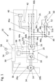
- Fig. 1 shows the electric and electronic parts of an elevator 10 comprising a frequency converter 12 driving an elevator motor 14.
- the frequency converter 12 comprises a rectifier bridge 16, an inverter bridge 18 and a DC link 20 located in between.
- the inverter bridge 18 is connected to the motor 14 and the rectifier bridge 16 is connected to three phase supply lines 22a, 22b, 22c which comprise an LCL filter 24 as well as a mains switch 26 and are connected with the AC phases L1, L2, L3 of a public AC electricity network.
- the elevator motor 14 comprises two elevator brakes 28a, 28b which are controlled by a control device 30 of the elevator 10 having an integrated safety device 32 which may also be separate from the control device.
- the control device 30 is connected with a tachometer 34 enabling the control device 30 to obtain a signal regarding the speed of the elevator motor as well as with a position sensor 36 informing the control device and of course the safety device 32 of the position of the elevator car in the shaft, or whether the car has reached a door zone (door zone sensor).
- the control device 30 controls the inverter bridge 18 as well as the rectifier bridge 16 via control lines.
- the control device 30 also controls a backup power supply 38 which preferably comprises a battery and/or a supercapacitor or the like.
- the backup power supply 38 is controlled by the control device 30 or by the safety device 32, respectively.
- At least one load circuit 40 for example any kind of elevator electrification and/or preferably a door operator of the elevator car, is connected to two of the phase supply lines 22a, 22b via an interruption switch 42 which is controlled by the safety device 32.
- the mains switch 26 is controlled by the safety device 32.
- the LCL filter 24 comprises first and second impedances 44a-c, 46a-c, e.g. coils as well as capacitors 48a-c which have a common terminal 49 which is connected to a first input 51a of an op-amplifier 52 which are forming parts of an earth fault detection circuit 50.
- the second input 51b is connected to earth.
- the output of the op-amplifier is connected to a transmission node 54 which may be an opto-coupler, a wireless transmitter or a cable, whereby the corresponding receiving part to the transmission node 54 is a receiver node 56 connected with the control device or the safety device 32, respectively.
- the control device 30 is also connected with a safety chain 58 so that the control device 30 of the elevator 10 also gets other safety-related information from the motor, from the elevator shaft, from the landing doors and the car doors and from all other safety-relevant parts of the elevator.
- the elevator works as follows: In case of a mains power off, the safety device 32 immediately controls the mains switch 26 to open and the interruption switch 42 to close and simultaneously it controls the backup power supply 38 to be connected with the DC link 20 via a connecting switch 39. Simultaneously, the rectifier bridge 16 is controlled to produce an alternating current, preferably 230 V AC, in two phase supply lines 22a, 22b to which also the at least one load circuit 40 is connected via the now closed interruption switch 42. Via this solution, the load circuit, for example the door operator of the elevator car, can still be kept working so that the car doors may be opened when the elevator car reaches a landing.
- the earth fault protection circuit 50 is provided to detect an earth fault in the arrangement of the load circuit 40 and is coupled thereto via its first input terminal 51a and the common terminal 49 of the capacitors 48a-c of the LCL circuit 24.
- the other input terminal 51b is connected to earth.
- an earth fault indication signal between the op-amplifier inputs 51a and 51b of the earth fault detection circuit 50 is monitored and if there is an earth fault in the load circuit 40, this leads to a signal between the two input terminals 51a, 51b of the op-amplifier 52.
- the output of the op-amplifier 52 is connected to the transmission node 54 which informs the safety device 32 as well as the control device 30 that an earth fault is present in the load circuit 40.
- the safety device 32 is then able to take the necessary measures to bring the elevator to a safe stop as an earth fault in the load circuit is not a severe fault.
- the safety device 32 indicates the earth fault to the control device which then controls the elevator motor to drive the elevator car to the next landing door in the current driving direction whereby the car speed is monitored via the tachometer 34 and the arrival of the elevator car at landing zone or door zone is monitored via the position sensor 36.
- the control device 30 stops the motor and de-energizes the brakes 28 with the energy of the backup power supply 38 which is connected to the DC link 20.
- the brake drive for the elevator brakes 28a and 28b is connected to the DC link.
- Fig. 1 the backup power supply is connected only to the DC link.
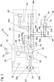
- the embodiment of Fig. 2 is nearly identical to Fig. 1 so that identical or functionally similar components are designated with the same reference numbers.
- Fig. 2 - in contrast to the embodiment of Fig. 1 - the backup power supply is connected in parallel with the series-connected rectifier bridge 16 and the first impedance 44a,b,c of the phase supply line 22a,b,c.
- the negative terminal of the backup power supply 38 is connected to the DC link 20 and its positive terminal is connected to one of the phase supply lines 22a, 22b or 22c, so that the negative terminal is all the time connected to the negative branch of the DC link and the positive terminal is connectable with a controllable switch to one phase supply line 22a, 22b, 22c of the mains L1, L2, L3.
- the positive terminal is connected such that an a first impedance 44a, 44b, 44c is connected between the rectifier bridge 16 and the connection point of the positive terminal to the phase supply line 22a, 22b, 22c.
- the series-connected impedance 44a, 44b, 44c and rectifier bridge 16 may be used as a boost converter to boost backup battery voltage to the DC link voltage level.
- the load is in this case connected to the other two phase supply lines 22a, 22b, 22c.
- the rectifier bridge 16 may boost a backup battery supply 36 while simultaneously converting the DC link voltage into AC for the load connected with the at least two supply lines 22a, 22b, 22c.
Landscapes
- Engineering & Computer Science (AREA)
- Automation & Control Theory (AREA)
- Power Engineering (AREA)
- Elevator Control (AREA)
Claims (14)
- Ascenseur (10) comprenant au moins une cabine d'ascenseur déplacée par au moins un moteur d'ascenseur, lequel moteur d'ascenseur est entraîné par un convertisseur de fréquence (12) commandé par un moyen de commande (30) de l'ascenseur,le convertisseur de fréquence (12) comprenant un pont redresseur (16), un pont inverseur (18) et une liaison en courant continu (20) reliée entre ceux-ci, le pont inverseur (18) étant relié au moteur d'ascenseur (14) et le pont redresseur (16) étant relié au réseau électrique à courant alternatif (L1, L2, L3) par le biais de trois lignes d'alimentation de phase (22a, 22b, 22c) comprenant un filtre LCL (24) et un interrupteur de réseau électrique (26),lequel ascenseur (10) comprend en outre un moyen de sécurité (32) du moyen de commande (30), lequel en cas de panne de courant de réseau électrique est configuré pour couper l'interrupteur de réseau électrique (26), dans lequel ascenseur un circuit de protection contre les défauts à la terre (50) est prévu, caractérisé en ce que l'ascenseur (10) comprend en outre une alimentation électrique de secours (38) et en ce que le moyen de sécurité (32) est en cas de panne de courant de réseau électrique configuré pour relier l'alimentation électrique de secours (38) à la liaison en courant continu (20) et/ou à au moins une ligne d'alimentation de phase (22a, 22b, 22c), que le pont redresseur (16) est un pont redresseur bidirectionnel qui est configuré pour convertir le courant continu alimenté vers la liaison en courant continu (20) à partir de l'alimentation électrique de secours (38) en une tension à courant alternatif alimentée vers au moins deux (22a, 22b) des lignes d'alimentation de phase (22a, 22b, 22c) reliées à au moins un circuit de charge (40),dans lequel le circuit de protection contre les défauts à la terre (50) est prévu pour le circuit de charge (40) et est relié entre la terre et une borne commune (49) des condensateurs (48a, 48b, 48c) du filtre LCL (24) pour la surveillance d'un signal d'indication de défauts à la terre, et lequel circuit de protection contre les défauts à la terre (50) est configuré pour émettre un signal de défauts à la terre et/ou l'initiation de mesures de sécurité contre des défauts à la terre, en fonction du signal d'indication de défauts à la terre.
- Ascenseur selon la revendication 1, dans lequel l'alimentation électrique de secours (38) est reliée en parallèle à un pont redresseur et inducteur reliés en série de la ligne d'alimentation de phase (22a, 22b, 22c), de sorte que la borne négative de l'alimentation électrique de secours (38) est reliée à la liaison en courant continu (20) et sa borne positive est reliée à la ligne d'alimentation de phase (22a, 22b, 22c).
- Ascenseur (10) selon une des revendications précédentes, dans lequel la sortie (54) du circuit de protection contre les défauts à la terre (50) est reliée à une entrée (56) du moyen de sécurité (32) de l'ascenseur.
- Ascenseur (10) selon une des revendications précédentes, dans lequel un capteur de position (36) pour la cabine d'ascenseur est relié au moyen de sécurité (32).
- Ascenseur (10) selon une des revendications précédentes, dans lequel le circuit de charge (40) est relié aux lignes d'alimentation de phase (22a, 22b, 22c) sans l'intermédiation d'un transformateur d'isolation galvanique.
- Ascenseur (10) selon une des revendications précédentes, dans lequel le circuit de charge (40) est relié aux lignes d'alimentation de phase (22a, 22b, 22c) par le biais d'un interrupteur de coupure (42) commandé par le moyen de sécurité (32).
- Ascenseur (10) selon une des revendications précédentes, dans lequel le signal d'indication de défauts à la terre est un signal de courant ou de tension.
- Ascenseur (10) selon une des revendications précédentes, dans lequel le circuit de protection contre les défauts à la terre (50) comprend un amplificateur opérationnel (52).
- Ascenseur (10) selon une des revendications précédentes, dans lequel le moyen de sécurité (32) est relié au moyen de commande (30), lequel est configuré lors de la réception du signal de défauts à la terre pour entraîner la cabine dans la direction de déplacement vers la zone de porte suivante puis pour désactiver l'ascenseur.
- Ascenseur (10) selon une des revendications précédentes, dans lequel le circuit de protection contre les défauts à la terre (50) comprend un comparateur qui est configuré pour comparer le signal d'indication de défauts à la terre à une valeur de seuil, et pour émettre un signal de défauts à la terre lorsque la valeur de seuil est dépassée.
- Procédé destiné à faire fonctionner un ascenseur (10) en cas de panne de courant de réseau électrique,dans lequel procédé un ascenseur (10) est utilisé en ayant au moins une cabine d'ascenseur déplacée par au moins un moteur d'ascenseur, lequel moteur d'ascenseur est entraîné par un convertisseur de fréquence (12) commandé par un moyen de commande (30) de l'ascenseur, dans lequel une protection contre les défauts à la terre est prévue, le convertisseur de fréquence (12) comprenant un pont redresseur (16), un pont inverseur (18) et une liaison en courant continu (20) reliée entre ceux-ci, le pont inverseur (18) étant relié au moteur d'ascenseur (14) et le pont redresseur (16) étant relié au réseau d'alimentation en courant alternatif (L1, L2, L3) par le biais de trois lignes d'alimentation de phase (22a, 22b, 22c) comprenant un filtre LCL (24) et un interrupteur de réseau électrique (26),dans lequel l'ascenseur (10) comprend en outre un moyen de sécurité (32) du moyen de commande (30), lequel en cas de panne de courant de réseau électrique coupe l'interrupteur de réseau électrique (26), caractérisé en ce que le pont redresseur est un pont redresseur bidirectionnel (16), que l'ascenseur (10) comprend en outre une alimentation électrique de secours (38), que le moyen de sécurité (32) relie en cas de panne de courant de réseau électrique l'alimentation électrique de secours (38) à la liaison en courant continu (20) et/ou à une ligne d'alimentation de phase (22a,22b,22c), et le pont redresseur (16) convertit le courant continu alimenté vers la liaison en courant continu (20) à partir de l'alimentation électrique de secours (38) en une tension à courant alternatif alimentée vers au moins deux (22a, 22b) des lignes d'alimentation de phase (22a, 22b, 22c), auxquelles au moins deux lignes d'alimentation (22a, 22b) est relié au moins un circuit de charge (40), dans lequel la protection contre les défauts à la terre est prévue en surveillant un signal d'indication de défauts à la terre entre la terre et une borne commune des condensateurs (48a, 48b, 48c) d'au moins deux phases du filtre LCL (24), et en émettant un signal de défauts à la terre et/ou initiant des mesures de sécurité de défauts à la terre, en fonction du signal d'indication de défauts à la terre.
- Procédé selon la revendication 11, dans lequel les mesures de sécurité comprennent l'entraînement de la cabine d'ascenseur vers la zone de porte suivante dans la direction de déplacement.
- Procédé selon la revendication 11 ou 12, dans lequel les mesures de sécurité comprennent la désactivation de la cabine d'ascenseur après que la cabine soit arrêtée ou se trouve dans une zone de porte de l'ascenseur.
- Procédé selon une des revendications 11 à 13, dans lequel les mesures de sécurité comprennent l'indication d'un défaut à la terre de circuit de charge à un centre de maintenance à distance.
Priority Applications (3)
| Application Number | Priority Date | Filing Date | Title |
|---|---|---|---|
| EP18191634.7A EP3617110B1 (fr) | 2018-08-30 | 2018-08-30 | Entrainement de moteur d'ascenseur avec un contrôle de sécurité d'un ascenseur en cas de panne de puissance |
| US16/451,267 US11697574B2 (en) | 2018-08-30 | 2019-06-25 | Elevator |
| CN201910700109.9A CN110872035B (zh) | 2018-08-30 | 2019-07-31 | 电梯 |
Applications Claiming Priority (1)
| Application Number | Priority Date | Filing Date | Title |
|---|---|---|---|
| EP18191634.7A EP3617110B1 (fr) | 2018-08-30 | 2018-08-30 | Entrainement de moteur d'ascenseur avec un contrôle de sécurité d'un ascenseur en cas de panne de puissance |
Publications (2)
| Publication Number | Publication Date |
|---|---|
| EP3617110A1 EP3617110A1 (fr) | 2020-03-04 |
| EP3617110B1 true EP3617110B1 (fr) | 2022-02-23 |
Family
ID=63449331
Family Applications (1)
| Application Number | Title | Priority Date | Filing Date |
|---|---|---|---|
| EP18191634.7A Active EP3617110B1 (fr) | 2018-08-30 | 2018-08-30 | Entrainement de moteur d'ascenseur avec un contrôle de sécurité d'un ascenseur en cas de panne de puissance |
Country Status (3)
| Country | Link |
|---|---|
| US (1) | US11697574B2 (fr) |
| EP (1) | EP3617110B1 (fr) |
| CN (1) | CN110872035B (fr) |
Families Citing this family (5)
| Publication number | Priority date | Publication date | Assignee | Title |
|---|---|---|---|---|
| US11084688B2 (en) * | 2018-12-04 | 2021-08-10 | Reynolds & Reynolds Electronics, Inc. | Rescue/evacuation self-testing system for traction elevators |
| US20210078822A1 (en) * | 2019-09-13 | 2021-03-18 | Harmar Mobility Llc | Vertical platform lift and control system |
| US20210101777A1 (en) * | 2019-10-03 | 2021-04-08 | Otis Elevator Company | Elevator brake control |
| CN114275640B (zh) * | 2021-12-30 | 2024-08-09 | 苏州汇川控制技术有限公司 | 电梯控制器及电梯 |
| CN115503677B (zh) * | 2022-09-14 | 2024-09-03 | 柳州五菱汽车工业有限公司 | 一种电液复合制动系统及其控制方法 |
Citations (1)
| Publication number | Priority date | Publication date | Assignee | Title |
|---|---|---|---|---|
| EP0278988B1 (fr) * | 1986-08-22 | 1993-08-04 | Otis Elevator Company | Dispositif de commande d'un moteur a courant alternatif |
Family Cites Families (12)
| Publication number | Priority date | Publication date | Assignee | Title |
|---|---|---|---|---|
| JPH0697875B2 (ja) * | 1987-05-20 | 1994-11-30 | 日本オ−チス・エレベ−タ株式会社 | エレベ−タ駆動用インバ−タ |
| FI112733B (fi) * | 1994-09-30 | 2003-12-31 | Kone Corp | Menetelmä ja laitteisto tahtimoottorin jarruttamiseksi |
| US6163472A (en) * | 1999-05-12 | 2000-12-19 | Otis Elevator Company | Elevator DC motor drive with unity power factor, including regeneration |
| CN1416614A (zh) * | 2000-03-08 | 2003-05-07 | 株式会社安川电机 | Pwm周波变换器和电源失常检测电路 |
| WO2008100259A1 (fr) * | 2007-02-13 | 2008-08-21 | Otis Elevator Company | Operation de sauvetage automatique pour systeme d'entrainement regenerateur |
| FI123506B (fi) * | 2012-05-31 | 2013-06-14 | Kone Corp | Hissin käyttölaite sekä hissin turvajärjestely |
| FI124423B (fi) * | 2012-11-05 | 2014-08-29 | Kone Corp | Hissijärjestelmä, joka käsittää turvajärjestelyn hissin sähköturvallisuuden valvomiseksi |
| JP2014114107A (ja) * | 2012-12-07 | 2014-06-26 | Toshiba Elevator Co Ltd | エレベータ制御装置 |
| US9318992B2 (en) * | 2013-08-22 | 2016-04-19 | Yaskawa America, Inc. | Drive circuit for a pre-phase AC motor |
| EP3178768A1 (fr) * | 2015-12-07 | 2017-06-14 | Kone Corporation | Dispositif de conduite |
| EP3290375B1 (fr) * | 2016-08-29 | 2019-06-26 | KONE Corporation | Élévateur |
| EP3300203B1 (fr) * | 2016-09-26 | 2021-06-16 | Kone Corporation | Entrainement de moteur |
-
2018
- 2018-08-30 EP EP18191634.7A patent/EP3617110B1/fr active Active
-
2019
- 2019-06-25 US US16/451,267 patent/US11697574B2/en active Active
- 2019-07-31 CN CN201910700109.9A patent/CN110872035B/zh active Active
Patent Citations (1)
| Publication number | Priority date | Publication date | Assignee | Title |
|---|---|---|---|---|
| EP0278988B1 (fr) * | 1986-08-22 | 1993-08-04 | Otis Elevator Company | Dispositif de commande d'un moteur a courant alternatif |
Also Published As
| Publication number | Publication date |
|---|---|
| US11697574B2 (en) | 2023-07-11 |
| EP3617110A1 (fr) | 2020-03-04 |
| US20200071127A1 (en) | 2020-03-05 |
| CN110872035A (zh) | 2020-03-10 |
| CN110872035B (zh) | 2023-12-19 |
Similar Documents
| Publication | Publication Date | Title |
|---|---|---|
| EP3617110B1 (fr) | Entrainement de moteur d'ascenseur avec un contrôle de sécurité d'un ascenseur en cas de panne de puissance | |
| US7775328B2 (en) | Operation device for an elevator system | |
| JP4986541B2 (ja) | エレベータ制御装置 | |
| WO2011142121A1 (fr) | Véhicule à courant alternatif | |
| US11498806B2 (en) | Elevator | |
| JP6751012B2 (ja) | エレベーター | |
| US20130133987A1 (en) | Electricity supply apparatus and an elevator system | |
| CN102025133A (zh) | 电梯的安全电路 | |
| US11511965B2 (en) | Backup power supply for elevator | |
| FI119765B (fi) | Kuljetusjärjestelmän tehonsyöttölaitteisto | |
| US5278484A (en) | Procedure and apparatus for braking a squirrel-cage elevator motor fed by a frequency converter in fault situations | |
| JP2007001712A (ja) | エレベータ制御装置及びエレベータ運転方法 | |
| US8638055B2 (en) | Transport system | |
| JP2013234028A (ja) | エレベーター | |
| JP3669761B2 (ja) | エレベータ運転装置 | |
| CN215419712U (zh) | 一种电梯应急电源装置 | |
| WO2023105786A1 (fr) | Dispositif de sécurité électrique pour ascenseur, et dispositif d'ascenseur | |
| JP2006176257A (ja) | エレベータ制御装置 | |
| JPH03297778A (ja) | エレベーターの停電時運転装置 | |
| CN114476911A (zh) | 检测电转换器单元缺相或欠压的方法、控制单元及系统 | |
| KR20070097098A (ko) | 엘리베이터 시스템에 대한 작동 디바이스 | |
| CN116177350A (zh) | 电梯的停电时运转系统 | |
| JPH0859125A (ja) | リニアモータエレベーターの運転方法 | |
| CN107840219A (zh) | 抱闸线圈控制电路、方法、抱闸控制电源设备及电梯 | |
| JPH02305784A (ja) | エレベーターの非常時運転装置 |
Legal Events
| Date | Code | Title | Description |
|---|---|---|---|
| PUAI | Public reference made under article 153(3) epc to a published international application that has entered the european phase |
Free format text: ORIGINAL CODE: 0009012 |
|
| STAA | Information on the status of an ep patent application or granted ep patent |
Free format text: STATUS: THE APPLICATION HAS BEEN PUBLISHED |
|
| AK | Designated contracting states |
Kind code of ref document: A1 Designated state(s): AL AT BE BG CH CY CZ DE DK EE ES FI FR GB GR HR HU IE IS IT LI LT LU LV MC MK MT NL NO PL PT RO RS SE SI SK SM TR |
|
| AX | Request for extension of the european patent |
Extension state: BA ME |
|
| STAA | Information on the status of an ep patent application or granted ep patent |
Free format text: STATUS: REQUEST FOR EXAMINATION WAS MADE |
|
| 17P | Request for examination filed |
Effective date: 20200707 |
|
| RBV | Designated contracting states (corrected) |
Designated state(s): AL AT BE BG CH CY CZ DE DK EE ES FI FR GB GR HR HU IE IS IT LI LT LU LV MC MK MT NL NO PL PT RO RS SE SI SK SM TR |
|
| GRAP | Despatch of communication of intention to grant a patent |
Free format text: ORIGINAL CODE: EPIDOSNIGR1 |
|
| STAA | Information on the status of an ep patent application or granted ep patent |
Free format text: STATUS: GRANT OF PATENT IS INTENDED |
|
| GRAJ | Information related to disapproval of communication of intention to grant by the applicant or resumption of examination proceedings by the epo deleted |
Free format text: ORIGINAL CODE: EPIDOSDIGR1 |
|
| GRAP | Despatch of communication of intention to grant a patent |
Free format text: ORIGINAL CODE: EPIDOSNIGR1 |
|
| STAA | Information on the status of an ep patent application or granted ep patent |
Free format text: STATUS: GRANT OF PATENT IS INTENDED |
|
| INTG | Intention to grant announced |
Effective date: 20211011 |
|
| INTG | Intention to grant announced |
Effective date: 20211027 |
|
| GRAS | Grant fee paid |
Free format text: ORIGINAL CODE: EPIDOSNIGR3 |
|
| GRAA | (expected) grant |
Free format text: ORIGINAL CODE: 0009210 |
|
| STAA | Information on the status of an ep patent application or granted ep patent |
Free format text: STATUS: THE PATENT HAS BEEN GRANTED |
|
| AK | Designated contracting states |
Kind code of ref document: B1 Designated state(s): AL AT BE BG CH CY CZ DE DK EE ES FI FR GB GR HR HU IE IS IT LI LT LU LV MC MK MT NL NO PL PT RO RS SE SI SK SM TR |
|
| REG | Reference to a national code |
Ref country code: GB Ref legal event code: FG4D |
|
| REG | Reference to a national code |
Ref country code: CH Ref legal event code: EP |
|
| REG | Reference to a national code |
Ref country code: AT Ref legal event code: REF Ref document number: 1470315 Country of ref document: AT Kind code of ref document: T Effective date: 20220315 |
|
| REG | Reference to a national code |
Ref country code: IE Ref legal event code: FG4D |
|
| REG | Reference to a national code |
Ref country code: DE Ref legal event code: R096 Ref document number: 602018031134 Country of ref document: DE |
|
| REG | Reference to a national code |
Ref country code: LT Ref legal event code: MG9D |
|
| REG | Reference to a national code |
Ref country code: NL Ref legal event code: MP Effective date: 20220223 |
|
| REG | Reference to a national code |
Ref country code: AT Ref legal event code: MK05 Ref document number: 1470315 Country of ref document: AT Kind code of ref document: T Effective date: 20220223 |
|
| PG25 | Lapsed in a contracting state [announced via postgrant information from national office to epo] |
Ref country code: SE Free format text: LAPSE BECAUSE OF FAILURE TO SUBMIT A TRANSLATION OF THE DESCRIPTION OR TO PAY THE FEE WITHIN THE PRESCRIBED TIME-LIMIT Effective date: 20220223 Ref country code: RS Free format text: LAPSE BECAUSE OF FAILURE TO SUBMIT A TRANSLATION OF THE DESCRIPTION OR TO PAY THE FEE WITHIN THE PRESCRIBED TIME-LIMIT Effective date: 20220223 Ref country code: PT Free format text: LAPSE BECAUSE OF FAILURE TO SUBMIT A TRANSLATION OF THE DESCRIPTION OR TO PAY THE FEE WITHIN THE PRESCRIBED TIME-LIMIT Effective date: 20220623 Ref country code: NO Free format text: LAPSE BECAUSE OF FAILURE TO SUBMIT A TRANSLATION OF THE DESCRIPTION OR TO PAY THE FEE WITHIN THE PRESCRIBED TIME-LIMIT Effective date: 20220523 Ref country code: NL Free format text: LAPSE BECAUSE OF FAILURE TO SUBMIT A TRANSLATION OF THE DESCRIPTION OR TO PAY THE FEE WITHIN THE PRESCRIBED TIME-LIMIT Effective date: 20220223 Ref country code: LT Free format text: LAPSE BECAUSE OF FAILURE TO SUBMIT A TRANSLATION OF THE DESCRIPTION OR TO PAY THE FEE WITHIN THE PRESCRIBED TIME-LIMIT Effective date: 20220223 Ref country code: HR Free format text: LAPSE BECAUSE OF FAILURE TO SUBMIT A TRANSLATION OF THE DESCRIPTION OR TO PAY THE FEE WITHIN THE PRESCRIBED TIME-LIMIT Effective date: 20220223 Ref country code: ES Free format text: LAPSE BECAUSE OF FAILURE TO SUBMIT A TRANSLATION OF THE DESCRIPTION OR TO PAY THE FEE WITHIN THE PRESCRIBED TIME-LIMIT Effective date: 20220223 Ref country code: BG Free format text: LAPSE BECAUSE OF FAILURE TO SUBMIT A TRANSLATION OF THE DESCRIPTION OR TO PAY THE FEE WITHIN THE PRESCRIBED TIME-LIMIT Effective date: 20220523 |
|
| PG25 | Lapsed in a contracting state [announced via postgrant information from national office to epo] |
Ref country code: PL Free format text: LAPSE BECAUSE OF FAILURE TO SUBMIT A TRANSLATION OF THE DESCRIPTION OR TO PAY THE FEE WITHIN THE PRESCRIBED TIME-LIMIT Effective date: 20220223 Ref country code: LV Free format text: LAPSE BECAUSE OF FAILURE TO SUBMIT A TRANSLATION OF THE DESCRIPTION OR TO PAY THE FEE WITHIN THE PRESCRIBED TIME-LIMIT Effective date: 20220223 Ref country code: GR Free format text: LAPSE BECAUSE OF FAILURE TO SUBMIT A TRANSLATION OF THE DESCRIPTION OR TO PAY THE FEE WITHIN THE PRESCRIBED TIME-LIMIT Effective date: 20220524 Ref country code: FI Free format text: LAPSE BECAUSE OF FAILURE TO SUBMIT A TRANSLATION OF THE DESCRIPTION OR TO PAY THE FEE WITHIN THE PRESCRIBED TIME-LIMIT Effective date: 20220223 Ref country code: AT Free format text: LAPSE BECAUSE OF FAILURE TO SUBMIT A TRANSLATION OF THE DESCRIPTION OR TO PAY THE FEE WITHIN THE PRESCRIBED TIME-LIMIT Effective date: 20220223 |
|
| PG25 | Lapsed in a contracting state [announced via postgrant information from national office to epo] |
Ref country code: IS Free format text: LAPSE BECAUSE OF FAILURE TO SUBMIT A TRANSLATION OF THE DESCRIPTION OR TO PAY THE FEE WITHIN THE PRESCRIBED TIME-LIMIT Effective date: 20220623 |
|
| PG25 | Lapsed in a contracting state [announced via postgrant information from national office to epo] |
Ref country code: SM Free format text: LAPSE BECAUSE OF FAILURE TO SUBMIT A TRANSLATION OF THE DESCRIPTION OR TO PAY THE FEE WITHIN THE PRESCRIBED TIME-LIMIT Effective date: 20220223 Ref country code: SK Free format text: LAPSE BECAUSE OF FAILURE TO SUBMIT A TRANSLATION OF THE DESCRIPTION OR TO PAY THE FEE WITHIN THE PRESCRIBED TIME-LIMIT Effective date: 20220223 Ref country code: RO Free format text: LAPSE BECAUSE OF FAILURE TO SUBMIT A TRANSLATION OF THE DESCRIPTION OR TO PAY THE FEE WITHIN THE PRESCRIBED TIME-LIMIT Effective date: 20220223 Ref country code: EE Free format text: LAPSE BECAUSE OF FAILURE TO SUBMIT A TRANSLATION OF THE DESCRIPTION OR TO PAY THE FEE WITHIN THE PRESCRIBED TIME-LIMIT Effective date: 20220223 Ref country code: DK Free format text: LAPSE BECAUSE OF FAILURE TO SUBMIT A TRANSLATION OF THE DESCRIPTION OR TO PAY THE FEE WITHIN THE PRESCRIBED TIME-LIMIT Effective date: 20220223 Ref country code: CZ Free format text: LAPSE BECAUSE OF FAILURE TO SUBMIT A TRANSLATION OF THE DESCRIPTION OR TO PAY THE FEE WITHIN THE PRESCRIBED TIME-LIMIT Effective date: 20220223 |
|
| REG | Reference to a national code |
Ref country code: DE Ref legal event code: R097 Ref document number: 602018031134 Country of ref document: DE |
|
| PG25 | Lapsed in a contracting state [announced via postgrant information from national office to epo] |
Ref country code: AL Free format text: LAPSE BECAUSE OF FAILURE TO SUBMIT A TRANSLATION OF THE DESCRIPTION OR TO PAY THE FEE WITHIN THE PRESCRIBED TIME-LIMIT Effective date: 20220223 |
|
| PLBE | No opposition filed within time limit |
Free format text: ORIGINAL CODE: 0009261 |
|
| STAA | Information on the status of an ep patent application or granted ep patent |
Free format text: STATUS: NO OPPOSITION FILED WITHIN TIME LIMIT |
|
| 26N | No opposition filed |
Effective date: 20221124 |
|
| PG25 | Lapsed in a contracting state [announced via postgrant information from national office to epo] |
Ref country code: SI Free format text: LAPSE BECAUSE OF FAILURE TO SUBMIT A TRANSLATION OF THE DESCRIPTION OR TO PAY THE FEE WITHIN THE PRESCRIBED TIME-LIMIT Effective date: 20220223 |
|
| PG25 | Lapsed in a contracting state [announced via postgrant information from national office to epo] |
Ref country code: MC Free format text: LAPSE BECAUSE OF FAILURE TO SUBMIT A TRANSLATION OF THE DESCRIPTION OR TO PAY THE FEE WITHIN THE PRESCRIBED TIME-LIMIT Effective date: 20220223 |
|
| REG | Reference to a national code |
Ref country code: CH Ref legal event code: PL |
|
| PG25 | Lapsed in a contracting state [announced via postgrant information from national office to epo] |
Ref country code: LU Free format text: LAPSE BECAUSE OF NON-PAYMENT OF DUE FEES Effective date: 20220830 Ref country code: LI Free format text: LAPSE BECAUSE OF NON-PAYMENT OF DUE FEES Effective date: 20220831 Ref country code: CH Free format text: LAPSE BECAUSE OF NON-PAYMENT OF DUE FEES Effective date: 20220831 |
|
| REG | Reference to a national code |
Ref country code: BE Ref legal event code: MM Effective date: 20220831 |
|
| P01 | Opt-out of the competence of the unified patent court (upc) registered |
Effective date: 20230525 |
|
| PG25 | Lapsed in a contracting state [announced via postgrant information from national office to epo] |
Ref country code: IT Free format text: LAPSE BECAUSE OF FAILURE TO SUBMIT A TRANSLATION OF THE DESCRIPTION OR TO PAY THE FEE WITHIN THE PRESCRIBED TIME-LIMIT Effective date: 20220223 Ref country code: IE Free format text: LAPSE BECAUSE OF NON-PAYMENT OF DUE FEES Effective date: 20220830 |
|
| PG25 | Lapsed in a contracting state [announced via postgrant information from national office to epo] |
Ref country code: BE Free format text: LAPSE BECAUSE OF NON-PAYMENT OF DUE FEES Effective date: 20220831 |
|
| PGFP | Annual fee paid to national office [announced via postgrant information from national office to epo] |
Ref country code: GB Payment date: 20230822 Year of fee payment: 6 |
|
| PGFP | Annual fee paid to national office [announced via postgrant information from national office to epo] |
Ref country code: FR Payment date: 20230828 Year of fee payment: 6 Ref country code: DE Payment date: 20230821 Year of fee payment: 6 |
|
| PG25 | Lapsed in a contracting state [announced via postgrant information from national office to epo] |
Ref country code: HU Free format text: LAPSE BECAUSE OF FAILURE TO SUBMIT A TRANSLATION OF THE DESCRIPTION OR TO PAY THE FEE WITHIN THE PRESCRIBED TIME-LIMIT; INVALID AB INITIO Effective date: 20180830 |
|
| PG25 | Lapsed in a contracting state [announced via postgrant information from national office to epo] |
Ref country code: CY Free format text: LAPSE BECAUSE OF FAILURE TO SUBMIT A TRANSLATION OF THE DESCRIPTION OR TO PAY THE FEE WITHIN THE PRESCRIBED TIME-LIMIT Effective date: 20220223 |
|
| PG25 | Lapsed in a contracting state [announced via postgrant information from national office to epo] |
Ref country code: MK Free format text: LAPSE BECAUSE OF FAILURE TO SUBMIT A TRANSLATION OF THE DESCRIPTION OR TO PAY THE FEE WITHIN THE PRESCRIBED TIME-LIMIT Effective date: 20220223 |
|
| PG25 | Lapsed in a contracting state [announced via postgrant information from national office to epo] |
Ref country code: TR Free format text: LAPSE BECAUSE OF FAILURE TO SUBMIT A TRANSLATION OF THE DESCRIPTION OR TO PAY THE FEE WITHIN THE PRESCRIBED TIME-LIMIT Effective date: 20220223 |