EP3616777A1 - High pd content diesel oxidation catalyst with improved hydrothermal durability - Google Patents
High pd content diesel oxidation catalyst with improved hydrothermal durability Download PDFInfo
- Publication number
- EP3616777A1 EP3616777A1 EP19199595.0A EP19199595A EP3616777A1 EP 3616777 A1 EP3616777 A1 EP 3616777A1 EP 19199595 A EP19199595 A EP 19199595A EP 3616777 A1 EP3616777 A1 EP 3616777A1
- Authority
- EP
- European Patent Office
- Prior art keywords
- catalyst
- overcoat
- gcf
- slurry
- zeolite
- Prior art date
- Legal status (The legal status is an assumption and is not a legal conclusion. Google has not performed a legal analysis and makes no representation as to the accuracy of the status listed.)
- Withdrawn
Links
- 239000003054 catalyst Substances 0.000 title claims abstract description 107
- 238000007254 oxidation reaction Methods 0.000 title claims abstract description 43
- 230000003647 oxidation Effects 0.000 title claims abstract description 42
- 238000007906 compression Methods 0.000 claims abstract description 16
- 230000006835 compression Effects 0.000 claims abstract description 16
- 231100000331 toxic Toxicity 0.000 claims abstract description 9
- 230000002588 toxic effect Effects 0.000 claims abstract description 9
- KDLHZDBZIXYQEI-UHFFFAOYSA-N palladium Substances [Pd] KDLHZDBZIXYQEI-UHFFFAOYSA-N 0.000 claims description 162
- BASFCYQUMIYNBI-UHFFFAOYSA-N platinum Substances [Pt] BASFCYQUMIYNBI-UHFFFAOYSA-N 0.000 claims description 120
- 239000010457 zeolite Substances 0.000 claims description 66
- HNPSIPDUKPIQMN-UHFFFAOYSA-N dioxosilane;oxo(oxoalumanyloxy)alumane Chemical compound O=[Si]=O.O=[Al]O[Al]=O HNPSIPDUKPIQMN-UHFFFAOYSA-N 0.000 claims description 61
- 229910021536 Zeolite Inorganic materials 0.000 claims description 60
- PNEYBMLMFCGWSK-UHFFFAOYSA-N aluminium oxide Inorganic materials [O-2].[O-2].[O-2].[Al+3].[Al+3] PNEYBMLMFCGWSK-UHFFFAOYSA-N 0.000 claims description 39
- 239000000463 material Substances 0.000 claims description 34
- 239000000203 mixture Substances 0.000 claims description 34
- 239000000758 substrate Substances 0.000 claims description 25
- MCMNRKCIXSYSNV-UHFFFAOYSA-N Zirconium dioxide Chemical compound O=[Zr]=O MCMNRKCIXSYSNV-UHFFFAOYSA-N 0.000 claims description 20
- 230000009849 deactivation Effects 0.000 claims description 16
- 239000010948 rhodium Substances 0.000 claims description 13
- 239000003344 environmental pollutant Substances 0.000 claims description 11
- 231100000719 pollutant Toxicity 0.000 claims description 11
- GWEVSGVZZGPLCZ-UHFFFAOYSA-N Titan oxide Chemical compound O=[Ti]=O GWEVSGVZZGPLCZ-UHFFFAOYSA-N 0.000 claims description 10
- 229910052760 oxygen Inorganic materials 0.000 claims description 10
- QVGXLLKOCUKJST-UHFFFAOYSA-N atomic oxygen Chemical compound [O] QVGXLLKOCUKJST-UHFFFAOYSA-N 0.000 claims description 9
- 239000001301 oxygen Substances 0.000 claims description 9
- 229910052703 rhodium Inorganic materials 0.000 claims description 8
- 150000003839 salts Chemical class 0.000 claims description 8
- 229910052788 barium Inorganic materials 0.000 claims description 7
- 125000005842 heteroatom Chemical group 0.000 claims description 7
- MHOVAHRLVXNVSD-UHFFFAOYSA-N rhodium atom Chemical compound [Rh] MHOVAHRLVXNVSD-UHFFFAOYSA-N 0.000 claims description 7
- 239000011232 storage material Substances 0.000 claims description 7
- 229910052746 lanthanum Inorganic materials 0.000 claims description 6
- 229910052710 silicon Inorganic materials 0.000 claims description 5
- 229910052742 iron Inorganic materials 0.000 claims description 4
- 238000005067 remediation Methods 0.000 claims description 4
- 229910052726 zirconium Inorganic materials 0.000 claims description 4
- JYIBXUUINYLWLR-UHFFFAOYSA-N aluminum;calcium;potassium;silicon;sodium;trihydrate Chemical compound O.O.O.[Na].[Al].[Si].[K].[Ca] JYIBXUUINYLWLR-UHFFFAOYSA-N 0.000 claims description 3
- DSAJWYNOEDNPEQ-UHFFFAOYSA-N barium atom Chemical compound [Ba] DSAJWYNOEDNPEQ-UHFFFAOYSA-N 0.000 claims description 3
- UNYSKUBLZGJSLV-UHFFFAOYSA-L calcium;1,3,5,2,4,6$l^{2}-trioxadisilaluminane 2,4-dioxide;dihydroxide;hexahydrate Chemical compound O.O.O.O.O.O.[OH-].[OH-].[Ca+2].O=[Si]1O[Al]O[Si](=O)O1.O=[Si]1O[Al]O[Si](=O)O1 UNYSKUBLZGJSLV-UHFFFAOYSA-L 0.000 claims description 3
- 229910052676 chabazite Inorganic materials 0.000 claims description 3
- 229910001603 clinoptilolite Inorganic materials 0.000 claims description 3
- 229910001657 ferrierite group Inorganic materials 0.000 claims description 3
- 229910052680 mordenite Inorganic materials 0.000 claims description 3
- 239000010970 precious metal Substances 0.000 claims description 3
- 239000002019 doping agent Substances 0.000 claims description 2
- 239000012013 faujasite Substances 0.000 claims description 2
- FZLIPJUXYLNCLC-UHFFFAOYSA-N lanthanum atom Chemical compound [La] FZLIPJUXYLNCLC-UHFFFAOYSA-N 0.000 claims description 2
- 238000010791 quenching Methods 0.000 abstract description 46
- 238000013461 design Methods 0.000 abstract description 25
- 230000001965 increasing effect Effects 0.000 abstract description 24
- 230000000171 quenching effect Effects 0.000 abstract description 10
- 229930195733 hydrocarbon Natural products 0.000 description 119
- 150000002430 hydrocarbons Chemical class 0.000 description 117
- 239000002002 slurry Substances 0.000 description 100
- UGFAIRIUMAVXCW-UHFFFAOYSA-N Carbon monoxide Chemical compound [O+]#[C-] UGFAIRIUMAVXCW-UHFFFAOYSA-N 0.000 description 87
- 229910002091 carbon monoxide Inorganic materials 0.000 description 86
- 229910052751 metal Inorganic materials 0.000 description 55
- 239000002184 metal Substances 0.000 description 55
- 239000010410 layer Substances 0.000 description 44
- 238000012360 testing method Methods 0.000 description 40
- QQONPFPTGQHPMA-UHFFFAOYSA-N Propene Chemical compound CC=C QQONPFPTGQHPMA-UHFFFAOYSA-N 0.000 description 37
- 230000000694 effects Effects 0.000 description 29
- 230000032683 aging Effects 0.000 description 28
- 238000006243 chemical reaction Methods 0.000 description 28
- 238000005516 engineering process Methods 0.000 description 28
- 206010021198 ichthyosis Diseases 0.000 description 27
- 239000000243 solution Substances 0.000 description 25
- 241000894007 species Species 0.000 description 23
- 230000008901 benefit Effects 0.000 description 21
- 230000003197 catalytic effect Effects 0.000 description 21
- 238000003756 stirring Methods 0.000 description 21
- 238000000034 method Methods 0.000 description 19
- 229910002651 NO3 Inorganic materials 0.000 description 17
- NHNBFGGVMKEFGY-UHFFFAOYSA-N Nitrate Chemical compound [O-][N+]([O-])=O NHNBFGGVMKEFGY-UHFFFAOYSA-N 0.000 description 17
- ATUOYWHBWRKTHZ-UHFFFAOYSA-N Propane Chemical compound CCC ATUOYWHBWRKTHZ-UHFFFAOYSA-N 0.000 description 17
- 238000006555 catalytic reaction Methods 0.000 description 14
- 238000000518 rheometry Methods 0.000 description 14
- 230000003247 decreasing effect Effects 0.000 description 13
- 230000001052 transient effect Effects 0.000 description 13
- 239000000843 powder Substances 0.000 description 12
- 239000007789 gas Substances 0.000 description 11
- 230000008929 regeneration Effects 0.000 description 11
- 238000011069 regeneration method Methods 0.000 description 11
- 239000006254 rheological additive Substances 0.000 description 11
- 238000001179 sorption measurement Methods 0.000 description 11
- 230000007423 decrease Effects 0.000 description 10
- 238000002485 combustion reaction Methods 0.000 description 9
- 229910052763 palladium Inorganic materials 0.000 description 9
- 229910052697 platinum Inorganic materials 0.000 description 9
- 231100000572 poisoning Toxicity 0.000 description 9
- 230000000607 poisoning effect Effects 0.000 description 9
- XLYOFNOQVPJJNP-UHFFFAOYSA-N water Substances O XLYOFNOQVPJJNP-UHFFFAOYSA-N 0.000 description 9
- 230000000903 blocking effect Effects 0.000 description 8
- 230000006870 function Effects 0.000 description 8
- TVMXDCGIABBOFY-UHFFFAOYSA-N octane Chemical compound CCCCCCCC TVMXDCGIABBOFY-UHFFFAOYSA-N 0.000 description 8
- 231100000614 poison Toxicity 0.000 description 8
- 239000002574 poison Substances 0.000 description 8
- 239000001294 propane Substances 0.000 description 8
- -1 thereof Substances 0.000 description 8
- 229910045601 alloy Inorganic materials 0.000 description 7
- 239000000956 alloy Substances 0.000 description 7
- 239000010953 base metal Substances 0.000 description 7
- 239000011248 coating agent Substances 0.000 description 7
- 238000000576 coating method Methods 0.000 description 7
- 238000002347 injection Methods 0.000 description 7
- 239000007924 injection Substances 0.000 description 7
- 150000002739 metals Chemical class 0.000 description 7
- 239000011369 resultant mixture Substances 0.000 description 7
- 159000000009 barium salts Chemical class 0.000 description 6
- 239000008367 deionised water Substances 0.000 description 6
- 238000002156 mixing Methods 0.000 description 6
- 239000003002 pH adjusting agent Substances 0.000 description 6
- 230000008569 process Effects 0.000 description 6
- 230000004044 response Effects 0.000 description 6
- 238000003860 storage Methods 0.000 description 6
- KJTLSVCANCCWHF-UHFFFAOYSA-N Ruthenium Chemical compound [Ru] KJTLSVCANCCWHF-UHFFFAOYSA-N 0.000 description 5
- 230000002860 competitive effect Effects 0.000 description 5
- 238000009472 formulation Methods 0.000 description 5
- 230000005764 inhibitory process Effects 0.000 description 5
- 229910052741 iridium Inorganic materials 0.000 description 5
- GKOZUEZYRPOHIO-UHFFFAOYSA-N iridium atom Chemical compound [Ir] GKOZUEZYRPOHIO-UHFFFAOYSA-N 0.000 description 5
- MRELNEQAGSRDBK-UHFFFAOYSA-N lanthanum oxide Inorganic materials [O-2].[O-2].[O-2].[La+3].[La+3] MRELNEQAGSRDBK-UHFFFAOYSA-N 0.000 description 5
- 230000007246 mechanism Effects 0.000 description 5
- KTUFCUMIWABKDW-UHFFFAOYSA-N oxo(oxolanthaniooxy)lanthanum Chemical compound O=[La]O[La]=O KTUFCUMIWABKDW-UHFFFAOYSA-N 0.000 description 5
- 229910052707 ruthenium Inorganic materials 0.000 description 5
- VYPSYNLAJGMNEJ-UHFFFAOYSA-N Silicium dioxide Chemical compound O=[Si]=O VYPSYNLAJGMNEJ-UHFFFAOYSA-N 0.000 description 4
- 238000005054 agglomeration Methods 0.000 description 4
- 230000002776 aggregation Effects 0.000 description 4
- 238000011161 development Methods 0.000 description 4
- 230000018109 developmental process Effects 0.000 description 4
- 239000000446 fuel Substances 0.000 description 4
- 230000005484 gravity Effects 0.000 description 4
- 230000014759 maintenance of location Effects 0.000 description 4
- 238000004519 manufacturing process Methods 0.000 description 4
- 229910044991 metal oxide Inorganic materials 0.000 description 4
- 150000004706 metal oxides Chemical class 0.000 description 4
- 230000001590 oxidative effect Effects 0.000 description 4
- GPNDARIEYHPYAY-UHFFFAOYSA-N palladium(ii) nitrate Chemical compound [Pd+2].[O-][N+]([O-])=O.[O-][N+]([O-])=O GPNDARIEYHPYAY-UHFFFAOYSA-N 0.000 description 4
- 239000004071 soot Substances 0.000 description 4
- 229910018879 Pt—Pd Inorganic materials 0.000 description 3
- 230000008859 change Effects 0.000 description 3
- 229910052593 corundum Inorganic materials 0.000 description 3
- 238000003795 desorption Methods 0.000 description 3
- 230000002708 enhancing effect Effects 0.000 description 3
- 239000011888 foil Substances 0.000 description 3
- 230000006872 improvement Effects 0.000 description 3
- VNWKTOKETHGBQD-UHFFFAOYSA-N methane Chemical compound C VNWKTOKETHGBQD-UHFFFAOYSA-N 0.000 description 3
- 230000004048 modification Effects 0.000 description 3
- 238000012986 modification Methods 0.000 description 3
- 230000000717 retained effect Effects 0.000 description 3
- 238000005245 sintering Methods 0.000 description 3
- URGAHOPLAPQHLN-UHFFFAOYSA-N sodium aluminosilicate Chemical compound [Na+].[Al+3].[O-][Si]([O-])=O.[O-][Si]([O-])=O URGAHOPLAPQHLN-UHFFFAOYSA-N 0.000 description 3
- 229910001220 stainless steel Inorganic materials 0.000 description 3
- 229910001845 yogo sapphire Inorganic materials 0.000 description 3
- IJGRMHOSHXDMSA-UHFFFAOYSA-N Atomic nitrogen Chemical compound N#N IJGRMHOSHXDMSA-UHFFFAOYSA-N 0.000 description 2
- 239000004215 Carbon black (E152) Substances 0.000 description 2
- 206010011906 Death Diseases 0.000 description 2
- 239000004594 Masterbatch (MB) Substances 0.000 description 2
- PXHVJJICTQNCMI-UHFFFAOYSA-N Nickel Chemical compound [Ni] PXHVJJICTQNCMI-UHFFFAOYSA-N 0.000 description 2
- NINIDFKCEFEMDL-UHFFFAOYSA-N Sulfur Chemical compound [S] NINIDFKCEFEMDL-UHFFFAOYSA-N 0.000 description 2
- 230000002411 adverse Effects 0.000 description 2
- 229910052782 aluminium Inorganic materials 0.000 description 2
- 230000002596 correlated effect Effects 0.000 description 2
- 230000004069 differentiation Effects 0.000 description 2
- 239000006185 dispersion Substances 0.000 description 2
- 238000009826 distribution Methods 0.000 description 2
- 230000007613 environmental effect Effects 0.000 description 2
- 239000011521 glass Substances 0.000 description 2
- 230000036541 health Effects 0.000 description 2
- 239000002808 molecular sieve Substances 0.000 description 2
- 239000002245 particle Substances 0.000 description 2
- 239000013618 particulate matter Substances 0.000 description 2
- 239000011148 porous material Substances 0.000 description 2
- 230000009467 reduction Effects 0.000 description 2
- 238000006722 reduction reaction Methods 0.000 description 2
- 230000035945 sensitivity Effects 0.000 description 2
- 239000000377 silicon dioxide Substances 0.000 description 2
- 239000007787 solid Substances 0.000 description 2
- 230000035882 stress Effects 0.000 description 2
- 229910052717 sulfur Inorganic materials 0.000 description 2
- 239000011593 sulfur Substances 0.000 description 2
- 229910017933 Ag—Al2O3 Inorganic materials 0.000 description 1
- 241000269350 Anura Species 0.000 description 1
- CURLTUGMZLYLDI-UHFFFAOYSA-N Carbon dioxide Chemical compound O=C=O CURLTUGMZLYLDI-UHFFFAOYSA-N 0.000 description 1
- VYZAMTAEIAYCRO-UHFFFAOYSA-N Chromium Chemical compound [Cr] VYZAMTAEIAYCRO-UHFFFAOYSA-N 0.000 description 1
- CBENFWSGALASAD-UHFFFAOYSA-N Ozone Chemical compound [O-][O+]=O CBENFWSGALASAD-UHFFFAOYSA-N 0.000 description 1
- 229910019142 PO4 Inorganic materials 0.000 description 1
- YXFVVABEGXRONW-UHFFFAOYSA-N Toluene Chemical compound CC1=CC=CC=C1 YXFVVABEGXRONW-UHFFFAOYSA-N 0.000 description 1
- 230000001133 acceleration Effects 0.000 description 1
- 238000003915 air pollution Methods 0.000 description 1
- 150000001336 alkenes Chemical class 0.000 description 1
- 150000001345 alkine derivatives Chemical class 0.000 description 1
- 239000004411 aluminium Substances 0.000 description 1
- XAGFODPZIPBFFR-UHFFFAOYSA-N aluminium Chemical compound [Al] XAGFODPZIPBFFR-UHFFFAOYSA-N 0.000 description 1
- 229910000323 aluminium silicate Inorganic materials 0.000 description 1
- 125000003118 aryl group Chemical group 0.000 description 1
- 230000003190 augmentative effect Effects 0.000 description 1
- 230000009286 beneficial effect Effects 0.000 description 1
- 239000011230 binding agent Substances 0.000 description 1
- 230000033228 biological regulation Effects 0.000 description 1
- 239000011449 brick Substances 0.000 description 1
- 238000001354 calcination Methods 0.000 description 1
- 230000000711 cancerogenic effect Effects 0.000 description 1
- 229910052799 carbon Inorganic materials 0.000 description 1
- 231100000315 carcinogenic Toxicity 0.000 description 1
- 238000010531 catalytic reduction reaction Methods 0.000 description 1
- 125000002091 cationic group Chemical group 0.000 description 1
- 239000000919 ceramic Substances 0.000 description 1
- 229910010293 ceramic material Inorganic materials 0.000 description 1
- 239000003795 chemical substances by application Substances 0.000 description 1
- 229910052804 chromium Inorganic materials 0.000 description 1
- 239000011651 chromium Substances 0.000 description 1
- 238000004581 coalescence Methods 0.000 description 1
- 210000001520 comb Anatomy 0.000 description 1
- 230000000052 comparative effect Effects 0.000 description 1
- 150000001875 compounds Chemical class 0.000 description 1
- 238000001816 cooling Methods 0.000 description 1
- 229910052878 cordierite Inorganic materials 0.000 description 1
- 230000007797 corrosion Effects 0.000 description 1
- 238000005260 corrosion Methods 0.000 description 1
- 238000005336 cracking Methods 0.000 description 1
- 230000007547 defect Effects 0.000 description 1
- 230000001627 detrimental effect Effects 0.000 description 1
- 239000002283 diesel fuel Substances 0.000 description 1
- 238000009792 diffusion process Methods 0.000 description 1
- JSKIRARMQDRGJZ-UHFFFAOYSA-N dimagnesium dioxido-bis[(1-oxido-3-oxo-2,4,6,8,9-pentaoxa-1,3-disila-5,7-dialuminabicyclo[3.3.1]nonan-7-yl)oxy]silane Chemical compound [Mg++].[Mg++].[O-][Si]([O-])(O[Al]1O[Al]2O[Si](=O)O[Si]([O-])(O1)O2)O[Al]1O[Al]2O[Si](=O)O[Si]([O-])(O1)O2 JSKIRARMQDRGJZ-UHFFFAOYSA-N 0.000 description 1
- 238000001035 drying Methods 0.000 description 1
- 231100000317 environmental toxin Toxicity 0.000 description 1
- 238000001704 evaporation Methods 0.000 description 1
- 230000008020 evaporation Effects 0.000 description 1
- 239000002657 fibrous material Substances 0.000 description 1
- 239000006260 foam Substances 0.000 description 1
- 238000011065 in-situ storage Methods 0.000 description 1
- 230000003993 interaction Effects 0.000 description 1
- 230000001788 irregular Effects 0.000 description 1
- 239000007788 liquid Substances 0.000 description 1
- 239000011159 matrix material Substances 0.000 description 1
- 230000005012 migration Effects 0.000 description 1
- 238000013508 migration Methods 0.000 description 1
- 238000003801 milling Methods 0.000 description 1
- 230000003278 mimic effect Effects 0.000 description 1
- 150000007522 mineralic acids Chemical class 0.000 description 1
- 229910052759 nickel Inorganic materials 0.000 description 1
- 229910052757 nitrogen Inorganic materials 0.000 description 1
- 150000007524 organic acids Chemical class 0.000 description 1
- 235000005985 organic acids Nutrition 0.000 description 1
- 238000012856 packing Methods 0.000 description 1
- 239000012188 paraffin wax Substances 0.000 description 1
- 230000036961 partial effect Effects 0.000 description 1
- NBIIXXVUZAFLBC-UHFFFAOYSA-K phosphate Chemical compound [O-]P([O-])([O-])=O NBIIXXVUZAFLBC-UHFFFAOYSA-K 0.000 description 1
- 239000010452 phosphate Substances 0.000 description 1
- 239000005373 porous glass Substances 0.000 description 1
- 230000001737 promoting effect Effects 0.000 description 1
- 239000002516 radical scavenger Substances 0.000 description 1
- 238000009790 rate-determining step (RDS) Methods 0.000 description 1
- 238000011084 recovery Methods 0.000 description 1
- 230000002829 reductive effect Effects 0.000 description 1
- 230000002000 scavenging effect Effects 0.000 description 1
- 229910010271 silicon carbide Inorganic materials 0.000 description 1
- HBMJWWWQQXIZIP-UHFFFAOYSA-N silicon carbide Chemical compound [Si+]#[C-] HBMJWWWQQXIZIP-UHFFFAOYSA-N 0.000 description 1
- 229910052709 silver Inorganic materials 0.000 description 1
- 239000010944 silver (metal) Substances 0.000 description 1
- 239000002356 single layer Substances 0.000 description 1
- 239000002594 sorbent Substances 0.000 description 1
- 230000006641 stabilisation Effects 0.000 description 1
- 239000010935 stainless steel Substances 0.000 description 1
- 239000000126 substance Substances 0.000 description 1
- 238000004448 titration Methods 0.000 description 1
- 231100000765 toxin Toxicity 0.000 description 1
- 239000003053 toxin Substances 0.000 description 1
- 108700012359 toxins Proteins 0.000 description 1
- 230000007704 transition Effects 0.000 description 1
- 230000007306 turnover Effects 0.000 description 1
- 229910052902 vermiculite Inorganic materials 0.000 description 1
- 239000010455 vermiculite Substances 0.000 description 1
- 235000019354 vermiculite Nutrition 0.000 description 1
- 229910052727 yttrium Inorganic materials 0.000 description 1
- VWQVUPCCIRVNHF-UHFFFAOYSA-N yttrium atom Chemical compound [Y] VWQVUPCCIRVNHF-UHFFFAOYSA-N 0.000 description 1
- 229910003158 γ-Al2O3 Inorganic materials 0.000 description 1
- 229910006415 θ-Al2O3 Inorganic materials 0.000 description 1
Images


Classifications
-
- B—PERFORMING OPERATIONS; TRANSPORTING
- B01—PHYSICAL OR CHEMICAL PROCESSES OR APPARATUS IN GENERAL
- B01D—SEPARATION
- B01D53/00—Separation of gases or vapours; Recovering vapours of volatile solvents from gases; Chemical or biological purification of waste gases, e.g. engine exhaust gases, smoke, fumes, flue gases, aerosols
- B01D53/34—Chemical or biological purification of waste gases
- B01D53/92—Chemical or biological purification of waste gases of engine exhaust gases
- B01D53/94—Chemical or biological purification of waste gases of engine exhaust gases by catalytic processes
-
- F—MECHANICAL ENGINEERING; LIGHTING; HEATING; WEAPONS; BLASTING
- F01—MACHINES OR ENGINES IN GENERAL; ENGINE PLANTS IN GENERAL; STEAM ENGINES
- F01N—GAS-FLOW SILENCERS OR EXHAUST APPARATUS FOR MACHINES OR ENGINES IN GENERAL; GAS-FLOW SILENCERS OR EXHAUST APPARATUS FOR INTERNAL COMBUSTION ENGINES
- F01N3/00—Exhaust or silencing apparatus having means for purifying, rendering innocuous, or otherwise treating exhaust
- F01N3/08—Exhaust or silencing apparatus having means for purifying, rendering innocuous, or otherwise treating exhaust for rendering innocuous
- F01N3/10—Exhaust or silencing apparatus having means for purifying, rendering innocuous, or otherwise treating exhaust for rendering innocuous by thermal or catalytic conversion of noxious components of exhaust
- F01N3/105—General auxiliary catalysts, e.g. upstream or downstream of the main catalyst
- F01N3/106—Auxiliary oxidation catalysts
-
- B—PERFORMING OPERATIONS; TRANSPORTING
- B01—PHYSICAL OR CHEMICAL PROCESSES OR APPARATUS IN GENERAL
- B01D—SEPARATION
- B01D53/00—Separation of gases or vapours; Recovering vapours of volatile solvents from gases; Chemical or biological purification of waste gases, e.g. engine exhaust gases, smoke, fumes, flue gases, aerosols
- B01D53/34—Chemical or biological purification of waste gases
- B01D53/92—Chemical or biological purification of waste gases of engine exhaust gases
- B01D53/94—Chemical or biological purification of waste gases of engine exhaust gases by catalytic processes
- B01D53/944—Simultaneously removing carbon monoxide, hydrocarbons or carbon making use of oxidation catalysts
-
- B—PERFORMING OPERATIONS; TRANSPORTING
- B01—PHYSICAL OR CHEMICAL PROCESSES OR APPARATUS IN GENERAL
- B01D—SEPARATION
- B01D53/00—Separation of gases or vapours; Recovering vapours of volatile solvents from gases; Chemical or biological purification of waste gases, e.g. engine exhaust gases, smoke, fumes, flue gases, aerosols
- B01D53/34—Chemical or biological purification of waste gases
- B01D53/92—Chemical or biological purification of waste gases of engine exhaust gases
- B01D53/94—Chemical or biological purification of waste gases of engine exhaust gases by catalytic processes
- B01D53/9459—Removing one or more of nitrogen oxides, carbon monoxide, or hydrocarbons by multiple successive catalytic functions; systems with more than one different function, e.g. zone coated catalysts
- B01D53/9463—Removing one or more of nitrogen oxides, carbon monoxide, or hydrocarbons by multiple successive catalytic functions; systems with more than one different function, e.g. zone coated catalysts with catalysts positioned on one brick
- B01D53/9468—Removing one or more of nitrogen oxides, carbon monoxide, or hydrocarbons by multiple successive catalytic functions; systems with more than one different function, e.g. zone coated catalysts with catalysts positioned on one brick in different layers
-
- B—PERFORMING OPERATIONS; TRANSPORTING
- B01—PHYSICAL OR CHEMICAL PROCESSES OR APPARATUS IN GENERAL
- B01J—CHEMICAL OR PHYSICAL PROCESSES, e.g. CATALYSIS OR COLLOID CHEMISTRY; THEIR RELEVANT APPARATUS
- B01J23/00—Catalysts comprising metals or metal oxides or hydroxides, not provided for in group B01J21/00
- B01J23/38—Catalysts comprising metals or metal oxides or hydroxides, not provided for in group B01J21/00 of noble metals
- B01J23/40—Catalysts comprising metals or metal oxides or hydroxides, not provided for in group B01J21/00 of noble metals of the platinum group metals
- B01J23/44—Palladium
-
- B—PERFORMING OPERATIONS; TRANSPORTING
- B01—PHYSICAL OR CHEMICAL PROCESSES OR APPARATUS IN GENERAL
- B01J—CHEMICAL OR PHYSICAL PROCESSES, e.g. CATALYSIS OR COLLOID CHEMISTRY; THEIR RELEVANT APPARATUS
- B01J23/00—Catalysts comprising metals or metal oxides or hydroxides, not provided for in group B01J21/00
- B01J23/38—Catalysts comprising metals or metal oxides or hydroxides, not provided for in group B01J21/00 of noble metals
- B01J23/54—Catalysts comprising metals or metal oxides or hydroxides, not provided for in group B01J21/00 of noble metals combined with metals, oxides or hydroxides provided for in groups B01J23/02 - B01J23/36
- B01J23/56—Platinum group metals
- B01J23/58—Platinum group metals with alkali- or alkaline earth metals
-
- B—PERFORMING OPERATIONS; TRANSPORTING
- B01—PHYSICAL OR CHEMICAL PROCESSES OR APPARATUS IN GENERAL
- B01J—CHEMICAL OR PHYSICAL PROCESSES, e.g. CATALYSIS OR COLLOID CHEMISTRY; THEIR RELEVANT APPARATUS
- B01J23/00—Catalysts comprising metals or metal oxides or hydroxides, not provided for in group B01J21/00
- B01J23/38—Catalysts comprising metals or metal oxides or hydroxides, not provided for in group B01J21/00 of noble metals
- B01J23/54—Catalysts comprising metals or metal oxides or hydroxides, not provided for in group B01J21/00 of noble metals combined with metals, oxides or hydroxides provided for in groups B01J23/02 - B01J23/36
- B01J23/56—Platinum group metals
- B01J23/63—Platinum group metals with rare earths or actinides
-
- B—PERFORMING OPERATIONS; TRANSPORTING
- B01—PHYSICAL OR CHEMICAL PROCESSES OR APPARATUS IN GENERAL
- B01J—CHEMICAL OR PHYSICAL PROCESSES, e.g. CATALYSIS OR COLLOID CHEMISTRY; THEIR RELEVANT APPARATUS
- B01J35/00—Catalysts, in general, characterised by their form or physical properties
-
- B—PERFORMING OPERATIONS; TRANSPORTING
- B01—PHYSICAL OR CHEMICAL PROCESSES OR APPARATUS IN GENERAL
- B01J—CHEMICAL OR PHYSICAL PROCESSES, e.g. CATALYSIS OR COLLOID CHEMISTRY; THEIR RELEVANT APPARATUS
- B01J35/00—Catalysts, in general, characterised by their form or physical properties
- B01J35/19—Catalysts containing parts with different compositions
-
- B—PERFORMING OPERATIONS; TRANSPORTING
- B01—PHYSICAL OR CHEMICAL PROCESSES OR APPARATUS IN GENERAL
- B01J—CHEMICAL OR PHYSICAL PROCESSES, e.g. CATALYSIS OR COLLOID CHEMISTRY; THEIR RELEVANT APPARATUS
- B01J37/00—Processes, in general, for preparing catalysts; Processes, in general, for activation of catalysts
- B01J37/02—Impregnation, coating or precipitation
- B01J37/0234—Impregnation and coating simultaneously
-
- B—PERFORMING OPERATIONS; TRANSPORTING
- B01—PHYSICAL OR CHEMICAL PROCESSES OR APPARATUS IN GENERAL
- B01J—CHEMICAL OR PHYSICAL PROCESSES, e.g. CATALYSIS OR COLLOID CHEMISTRY; THEIR RELEVANT APPARATUS
- B01J37/00—Processes, in general, for preparing catalysts; Processes, in general, for activation of catalysts
- B01J37/02—Impregnation, coating or precipitation
- B01J37/024—Multiple impregnation or coating
- B01J37/0242—Coating followed by impregnation
-
- B—PERFORMING OPERATIONS; TRANSPORTING
- B01—PHYSICAL OR CHEMICAL PROCESSES OR APPARATUS IN GENERAL
- B01J—CHEMICAL OR PHYSICAL PROCESSES, e.g. CATALYSIS OR COLLOID CHEMISTRY; THEIR RELEVANT APPARATUS
- B01J37/00—Processes, in general, for preparing catalysts; Processes, in general, for activation of catalysts
- B01J37/02—Impregnation, coating or precipitation
- B01J37/024—Multiple impregnation or coating
- B01J37/0244—Coatings comprising several layers
-
- B—PERFORMING OPERATIONS; TRANSPORTING
- B01—PHYSICAL OR CHEMICAL PROCESSES OR APPARATUS IN GENERAL
- B01J—CHEMICAL OR PHYSICAL PROCESSES, e.g. CATALYSIS OR COLLOID CHEMISTRY; THEIR RELEVANT APPARATUS
- B01J37/00—Processes, in general, for preparing catalysts; Processes, in general, for activation of catalysts
- B01J37/02—Impregnation, coating or precipitation
- B01J37/024—Multiple impregnation or coating
- B01J37/0246—Coatings comprising a zeolite
-
- F—MECHANICAL ENGINEERING; LIGHTING; HEATING; WEAPONS; BLASTING
- F01—MACHINES OR ENGINES IN GENERAL; ENGINE PLANTS IN GENERAL; STEAM ENGINES
- F01N—GAS-FLOW SILENCERS OR EXHAUST APPARATUS FOR MACHINES OR ENGINES IN GENERAL; GAS-FLOW SILENCERS OR EXHAUST APPARATUS FOR INTERNAL COMBUSTION ENGINES
- F01N3/00—Exhaust or silencing apparatus having means for purifying, rendering innocuous, or otherwise treating exhaust
- F01N3/08—Exhaust or silencing apparatus having means for purifying, rendering innocuous, or otherwise treating exhaust for rendering innocuous
- F01N3/10—Exhaust or silencing apparatus having means for purifying, rendering innocuous, or otherwise treating exhaust for rendering innocuous by thermal or catalytic conversion of noxious components of exhaust
- F01N3/103—Oxidation catalysts for HC and CO only
-
- B—PERFORMING OPERATIONS; TRANSPORTING
- B01—PHYSICAL OR CHEMICAL PROCESSES OR APPARATUS IN GENERAL
- B01D—SEPARATION
- B01D2255/00—Catalysts
- B01D2255/10—Noble metals or compounds thereof
- B01D2255/102—Platinum group metals
- B01D2255/1021—Platinum
-
- B—PERFORMING OPERATIONS; TRANSPORTING
- B01—PHYSICAL OR CHEMICAL PROCESSES OR APPARATUS IN GENERAL
- B01D—SEPARATION
- B01D2255/00—Catalysts
- B01D2255/10—Noble metals or compounds thereof
- B01D2255/102—Platinum group metals
- B01D2255/1023—Palladium
-
- B—PERFORMING OPERATIONS; TRANSPORTING
- B01—PHYSICAL OR CHEMICAL PROCESSES OR APPARATUS IN GENERAL
- B01D—SEPARATION
- B01D2255/00—Catalysts
- B01D2255/90—Physical characteristics of catalysts
- B01D2255/902—Multilayered catalyst
- B01D2255/9022—Two layers
-
- B—PERFORMING OPERATIONS; TRANSPORTING
- B01—PHYSICAL OR CHEMICAL PROCESSES OR APPARATUS IN GENERAL
- B01D—SEPARATION
- B01D2255/00—Catalysts
- B01D2255/90—Physical characteristics of catalysts
- B01D2255/903—Multi-zoned catalysts
- B01D2255/9032—Two zones
-
- B—PERFORMING OPERATIONS; TRANSPORTING
- B01—PHYSICAL OR CHEMICAL PROCESSES OR APPARATUS IN GENERAL
- B01D—SEPARATION
- B01D2255/00—Catalysts
- B01D2255/90—Physical characteristics of catalysts
- B01D2255/908—O2-storage component incorporated in the catalyst
-
- B—PERFORMING OPERATIONS; TRANSPORTING
- B01—PHYSICAL OR CHEMICAL PROCESSES OR APPARATUS IN GENERAL
- B01D—SEPARATION
- B01D2255/00—Catalysts
- B01D2255/90—Physical characteristics of catalysts
- B01D2255/912—HC-storage component incorporated in the catalyst
-
- B—PERFORMING OPERATIONS; TRANSPORTING
- B01—PHYSICAL OR CHEMICAL PROCESSES OR APPARATUS IN GENERAL
- B01D—SEPARATION
- B01D2257/00—Components to be removed
- B01D2257/50—Carbon oxides
- B01D2257/502—Carbon monoxide
-
- B—PERFORMING OPERATIONS; TRANSPORTING
- B01—PHYSICAL OR CHEMICAL PROCESSES OR APPARATUS IN GENERAL
- B01D—SEPARATION
- B01D2257/00—Components to be removed
- B01D2257/70—Organic compounds not provided for in groups B01D2257/00 - B01D2257/602
- B01D2257/702—Hydrocarbons
-
- B—PERFORMING OPERATIONS; TRANSPORTING
- B01—PHYSICAL OR CHEMICAL PROCESSES OR APPARATUS IN GENERAL
- B01D—SEPARATION
- B01D2258/00—Sources of waste gases
- B01D2258/01—Engine exhaust gases
- B01D2258/012—Diesel engines and lean burn gasoline engines
-
- B—PERFORMING OPERATIONS; TRANSPORTING
- B01—PHYSICAL OR CHEMICAL PROCESSES OR APPARATUS IN GENERAL
- B01J—CHEMICAL OR PHYSICAL PROCESSES, e.g. CATALYSIS OR COLLOID CHEMISTRY; THEIR RELEVANT APPARATUS
- B01J29/00—Catalysts comprising molecular sieves
- B01J29/04—Catalysts comprising molecular sieves having base-exchange properties, e.g. crystalline zeolites
- B01J29/06—Crystalline aluminosilicate zeolites; Isomorphous compounds thereof
- B01J29/70—Crystalline aluminosilicate zeolites; Isomorphous compounds thereof of types characterised by their specific structure not provided for in groups B01J29/08 - B01J29/65
- B01J29/7007—Zeolite Beta
-
- B—PERFORMING OPERATIONS; TRANSPORTING
- B01—PHYSICAL OR CHEMICAL PROCESSES OR APPARATUS IN GENERAL
- B01J—CHEMICAL OR PHYSICAL PROCESSES, e.g. CATALYSIS OR COLLOID CHEMISTRY; THEIR RELEVANT APPARATUS
- B01J35/00—Catalysts, in general, characterised by their form or physical properties
- B01J35/40—Catalysts, in general, characterised by their form or physical properties characterised by dimensions, e.g. grain size
-
- B—PERFORMING OPERATIONS; TRANSPORTING
- B01—PHYSICAL OR CHEMICAL PROCESSES OR APPARATUS IN GENERAL
- B01J—CHEMICAL OR PHYSICAL PROCESSES, e.g. CATALYSIS OR COLLOID CHEMISTRY; THEIR RELEVANT APPARATUS
- B01J37/00—Processes, in general, for preparing catalysts; Processes, in general, for activation of catalysts
- B01J37/0009—Use of binding agents; Moulding; Pressing; Powdering; Granulating; Addition of materials ameliorating the mechanical properties of the product catalyst
- B01J37/0027—Powdering
- B01J37/0036—Grinding
-
- F—MECHANICAL ENGINEERING; LIGHTING; HEATING; WEAPONS; BLASTING
- F01—MACHINES OR ENGINES IN GENERAL; ENGINE PLANTS IN GENERAL; STEAM ENGINES
- F01N—GAS-FLOW SILENCERS OR EXHAUST APPARATUS FOR MACHINES OR ENGINES IN GENERAL; GAS-FLOW SILENCERS OR EXHAUST APPARATUS FOR INTERNAL COMBUSTION ENGINES
- F01N2370/00—Selection of materials for exhaust purification
- F01N2370/02—Selection of materials for exhaust purification used in catalytic reactors
-
- F—MECHANICAL ENGINEERING; LIGHTING; HEATING; WEAPONS; BLASTING
- F01—MACHINES OR ENGINES IN GENERAL; ENGINE PLANTS IN GENERAL; STEAM ENGINES
- F01N—GAS-FLOW SILENCERS OR EXHAUST APPARATUS FOR MACHINES OR ENGINES IN GENERAL; GAS-FLOW SILENCERS OR EXHAUST APPARATUS FOR INTERNAL COMBUSTION ENGINES
- F01N2570/00—Exhaust treating apparatus eliminating, absorbing or adsorbing specific elements or compounds
- F01N2570/12—Hydrocarbons
Definitions
- the exhaust emissions from motor vehicles are a well known and significant source of air pollution.
- the most significant gaseous vehicular emissions comprise pollutants such as carbon monoxide (CO), oxides of nitrogen (NO and NO2 collectively NOx), and unburnt hydrocarbons (HC).
- the diesel exhaust stream also contains entrained solids, commonly referred to as particulate matter or soot, upon which may additionally be adsorbed volatile/soluble organic fraction (SOF).
- SOF volatile/soluble organic fraction
- diesel/compression ignition engines are their inherent lean burn operation, i.e. combustion occurs due to fuel compression under conditions of excess O2, which results in increased fuel economy and decreased emissions (in g/km) of CO, HC and CO2 cf. the stoichiometric gasoline engine.
- diesel engines offer increased durability and are able to provide high torque at low engine rpm and these attractive characteristics have helped diesel passenger cars gain a >50% market share in the Western Europe market.
- conventional diesel engines still do not meet the aforementioned legislative targets and thus a range of exhaust after-treatment technologies have been developed to address this requirement.
- the DOC is both the most widely studied and implemented technology, for examples see U.S. Pat. No. 5,371,056 , U.S. Pat. No. 5,462,907 , U.S. Pat. No. 6,153,160 , U.S. Pat. No. 6,274,107 , J. A. A. van den Tillaart, J. Leyrer, S. Eckhoff and E. S. Lox in Applied Catalysis B vol. 10, 1-3, p 53-68 (1996 ).
- the design of these systems and materials employed therein are somewhat generic and typically consist of a refractory oxide support e.g. an (modified) alumina, a hydrocarbon storage/release component and an active Precious Group Metal (PGM) to catalyse the oxidative conversion of the pollutants into more benign products (H2O and CO2).
- PGM Precious Group Metal
- HC storage/release component conventionally a microporous crystalline aluminosilicate also known as a Zeolite or molecular sieve
- a microporous crystalline aluminosilicate also known as a Zeolite or molecular sieve
- Zeolite or molecular sieve The introduction of the Zeolite in the DOC provides a mechanism for the low temperature condensative adsorption of a significant portion of the higher molecular weight unburnt HC species emitted during 'cold start' of the engine. This limits the potential for HC adsorption on active precious metal centres and their resultant poisoning by 'site-blocking'.
- the choice of metal(s) in the DOC is based upon their ability to offer the highest turnover frequency (number of reactions per second) with respect to the oxidation of CO and Hydrocarbon to CO2 and H2O at low temperatures and low concentrations of active component within the DOC formulation.
- Pt e.g. U.S. Pat. No. 5,627,124
- Pd has been employed as the primary catalytic species (e.g. US2008/0045405 A1 , U. Neuhausen, K. V. Klementiev, F.-W. Schütze, G. Miehe, H. Fuess and E. S. Lox in Applied Catalysis B: Environmental, vol. 60, 3-4, (2005), p 191-199 and references therein).
- the invention disclosed herein describes a new class of layered and zoned DOC systems capable of addressing the challenges and requirements outlined previously.
- This new class of Pd-rich DOCs provides both high activity but also enhanced hydrothermal durability, especially with regards to the cycle post-injection DPF regeneration cycles typical of modern vehicular applications, as compared to conventional DOC technologies.
- These benefits are realised by the combination of functionalised layers to introduce the capability of the DOC to resist 'quenching' i.e. transient active site blocking arising from (especially) HC or CO under lower temperatures i.e. 'cold start' conditions.
- the use of 'quench' tolerant overcoat with a second dedicated oxidation layer which itself may also be Pd rich, provides a synergy which enables high conversion of pollutants at lower temperatures and with increased hydrothermal durability.
- the present invention describes a method for removal of gaseous pollutants from the exhaust stream of a diesel/compression ignition engine. This is achieved by contacting the exhaust stream with the novel catalyst described herein, where the catalyst comprises a novel washcoat design comprising two functionalised layers which enable high catalytic performance over a range of PGM contents and ratios of Pt:Pd, including technologies enriched in Pd content.
- the present invention provides an oxidation catalyst, for the remediation of pollutants from the exhaust of a compression ignition comprising a carrier or substrate upon which is disposed at least two layers of washcoat wherein:
- the Pt:Pd ratio of the undercoat is about 1:1 and the Pt:Pd ratio of the overcoat is about 1:2.
- the overcoat may optionally contain salts or oxides of barium or lantherium.
- the refractory oxide support in the undercoat and/or the overcoat is alumina, a modified or heteroatom doped alumina, zirconia or titania or combinations thereof.
- the heteroatom dopant can be Si, Fe, Zr, Ba or La or combinations thereof.
- the optional zeolite in the undercoat and/or overcoat is selected from the group Beta (i), Chabazite, Clinoptilolite, Faujastie, Ferrierite, Mordenite, Offretite, Silicalite, zeolite X, zeolite Y, ultrastable zeolite Y, ZSM5, ZSM11, ZSM22 or other ZSM series material or structural isomorphs thereof, e.g. SAPO34 or mixtures thereof.
- the catalyst device of the invention has an inlet and an outlet and, and the overcoat is optionally applied to cover a length of about 5% to about 75% from the inlet, and the undercoat is applied to cover a length of about 95% to about 25% from the inlet.
- Another aspect of the invention relates to a diesel oxidation catalyst wherein the catalyst has an inlet and an outlet, wherein a washcoat zone is applied to cover a length of about 25% to about 95% from the inlet and the washcoat contains Pt:Pd at a ratio of about 2:3 to about 0:1 and a second washcoat zone is optionally applied to cover a length of about 5% to about 75% from the outlet and the washcoat contains Pt:Pd at a ratio of about 2:1 to about 1:2.
- a still further aspect of the invention relates to a method of treating exhaust gas comprising passing an exhaust gas over a catalytic device, comprising: a housing disposed around a substrate; an oxidation catalyst, for the remediation of pollutants from the exhaust of a compression ignition comprising a carrier or substrate upon which is disposed at least two layers of washcoat wherein:
- the catalytic device of the invention further includes a retention material disposed between the housing and the substrate.
- the present invention relates to the development and use of novel high Pd content diesel oxidation catalyst (DOC) for emission aftertreatment catalysis.
- DOC diesel oxidation catalyst
- This is made possible by the development of a specific layered or zoned strategy, wherein the distinct layers afford specific functionalities to the catalyst and work in concert to provide an effective synergy for overall improvements in performance and durability.
- the design herein employs a more conventional undercoat (pass 1) to facilitate the required CO, HC and NO oxidation reactions and a second layer or zone (pass 2), which is enriched in Pd or indeed Pd-only, which has been developed to provide the catalyst with a characteristic dubbed 'quench' tolerance.
- Both layers comprise typical base metal components e.g. alumina (or other suitable refractory oxide e.g. ZrO2, TiO2), zeolite for bulk HC storage/release and optionally an oxygen storage material based upon CeZrOx.
- Typical aluminas that may be employed in this invention include ⁇ -Al2O3, ⁇ -Al2O3, ⁇ -Al2O3, or other transition alumina. Additionally, the alumina could be modified e.g. by the inclusion of heteroatom species with cationic doping by Si, Fe, Zr, Ba or La preferred. However, notwithstanding these modifications the novel invention herein is not related to specific material development but rather to the demonstration of a previously less well understood transient deactivation mechanism and a means to overcome this limitation and thus gain significant improvements in the activity and hydrothermal durability of DOCs and especially Pd-rich DOCs.
- quench tolerance is proposed, without wishing to be bound by theory, to be based upon the transient active site blocking of PGM sites by 'toxic' HC species in the exhaust. While the idea of HC poisoning is well known it has been previously believed that the presence of zeolite in the DOC washcoat was sufficient to address this issue ( Applied Catalysis B, vol. 70, (2007), p 2 , Applied Catalysis A vol. 221, (2001), p 443 , U.S. Pat. No. 2,125,231 ). The data herein however contradict this assertion (see hereafter).
- zeolites have well defined channel and/or cage structures arising from the combination of primary building units (repeating structures derived from the assemblages of TO 4 tetrahedra, where T is Si or Al) e.g. for MFI zeolites the primary building unit is the 5-1 ring structure (see http://www.iza-structure.org/databases for further details).
- the combination of these primary building units gives rise to the secondary order within the zeolite and thus enforces limits upon the maximum size of species which may enter the structure, i.e. provides the 'molecular sieve' function.
- zeolite ⁇ the structure contains two 12 ring structures, one a regular ring of 5.6 by 5.6 ⁇ and a second more irregular ring of ca. 7.7 by 6.6 ⁇ (at maximum and minimum), and hence molecules with diameters (so-called critical diameters) larger than this are excluded and thus the zeolite cannot prevent adsorption of such large HCs e.g. poly-substituted aromatics or poly-aromatic species on active PGM sites.
- the first layer/pass/zone applied to the substrate hereafter the undercoat, comprises a refractory oxide support e.g. (modified/doped) alumina, zirconia etc. and optionally a zeolite and also optionally an OS material.
- the undercoat is characterised by possessing Pt and optionally Pd at a ratio of about Pt:Pd 20:1 to about 1:2.
- the second layer/zone hereafter overcoat.
- This overcoat again comprises a refractory oxide support e.g. (modified/doped) alumina, zirconia, titania etc. and optionally a zeolite and also optionally an OS material.
- the base metal oxide components of the undercoat and overcoat may be identical. This enables production of a 'white' washcoat which is split into two batches prior to coating and the appropriate PGM loads and ratios added individually.
- the overcoat also contains precious metal, but in this instance the washcoat is enriched in Pd such that the ratio of Pt:Pd is about 0:1 (i.e. Pd-only) to about 2:3.
- Pd i.e. Pd-only
- This strategy is contra to the teachings in US 2005/0045405 A1 wherein a layered design is also employed but this design is based upon a Pt-enriched overcoat and Pd-enriched undercoat.
- US 2005/0045405 A1 stresses the importance of avoiding Pd migration to the overcoat and that it is necessary to omit zeolite (HC storage component) from the undercoat, neither of these teachings are consistent with the current invention.
- this design is intended to maximise NO 2 production rather than provide optimised CO, HC and NO oxidation function. Further differentiation will be drawn in the following examples.
- the novel oxidation catalyst described herein is intended for the remediation of pollutants from the exhaust of a compression ignition engine. It comprises a carrier or substrate upon which is disposed at least two layers of washcoat wherein at least both layers comprise a refractory oxide support (alumina, heteroatom doped alumina e.g. Si, Fe, Zr, Ba or La, or zirconia as ZrO2, titania etc.), optionally a zeolite e.g.
- a refractory oxide support alumina, heteroatom doped alumina e.g. Si, Fe, Zr, Ba or La, or zirconia as ZrO2, titania etc.
- Beta ( ⁇ ), Chabazite, Clinoptilolite, Faujasite, Ferrierite, Mordenite, Offretite, Silicalite, zeolite X, zeolite Y, Ultrastable zeolite Y, ZSM5, ZSM11, ZSM22 or other ZSM series material or structural isomorphs thereof e.g. SAPO34 or mixtures thereof, optionally an oxygen storage material and primary catalytic metal(s) selected from the group of Precious Group Metals consisting of platinum, palladium, iridium, rhodium, ruthenium, alloys thereof, and combinations thereof.
- Precious Group Metals consisting of platinum, palladium, iridium, rhodium, ruthenium, alloys thereof, and combinations thereof.
- the layers of the catalyst may contain different base metal components or indeed identical components but the two layers are especially differentiated in that the second layer (overcoat) is substantially enriched in Pd content and particularly wherein the Pd to Pt ratio of the overcoat is greater than that of the undercoat.
- the Pt:Pd ratio of the undercoat is from about 20:1 to about 1:2 while the Pt:Pd ratio of the overcoat is from about 2:3 to about 0:1 i.e. a Pt-free, Pd-only layer.
- the catalyst may contain two layers wherein the Pt:Pd ratio of the undercoat is about 1:1 and the Pt:Pd ratio of the overcoat is about 1:2.
- the overcoat may additionally contain Rhodium.
- the overcoat may additionally be modified by the inclusion of salts or oxides of Barium and Lanthanum.
- the layers of the catalyst may also be expressed as zones e.g. wherein the catalyst has an inlet and an outlet, and the overcoat is applied to cover a length of about 5% to about 75% from the inlet.
- the undercoat is applied to cover a length of about 95% to about 25% from the inlet.
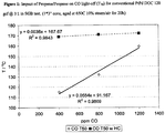
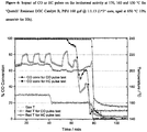
- FIG. 1 illustrates the Synthetic Gas Bench (SGB) performance data for a commercial Pt-Pd DOC (120 gram per cubic foot, hereafter gcf @ 3Pt:1Pd) after aging/stabilisation at 650° C. in steam/air for 20 h.
- the data contrasts the CO light-off temperatures (T50) at 400, 800 or 1200 ppm CO in the presence or absence of 150 ppm C1 propene/propane (3:1) (12% O2, 150 ppm NO, 5% CO2, 5% H2O, balance N2 at a total flow of 30 l/min, ramp 75-325° C. at 15° C./min).
- T50 CO light-off temperatures
- this phenomenon is a transient inhibition effect involving the preferential adsorption of propene on the active centres of the Pt-Pd required for O2 dissociative adsorption (the proposed rate limiting step in CO oxidation).
- This is consistent with the high sticking probability of propene on the high defect planes of PGM surfaces resulting in a site-blocking phenomenon which is only overcome at temperatures sufficient to facilitate oxidative desorption of the HC ( R. Burch and P. J. Millington, Catalysis Today, Vol 26(2), 1995, p 185 ). Since this temperature is independent of CO concentration then catalyst light-off exhibits the independent activity trace in FIG. 1 .
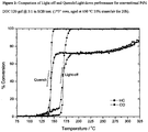
- FIG. 2 shows the full light-off (positive temperature ramp) and quench (negative temperature ramp/cooling cycle) for the commercial DOC of FIG. 1 .
- FIG. 2 shows the full light-off (positive temperature ramp) and quench (negative temperature ramp/cooling cycle) for the commercial DOC of FIG. 1 .
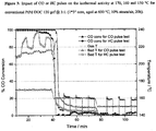
- FIG. 3 further examines the ability of CO and propene to 'quench' the catalytic oxidation function of the commercial DOC.
- This Figure contrasts the performance of the 120 gcf 3:1 DOC under isothermal conditions with transient pulses of either CO or HC viz.
- the DOC is exposed to 12% O2, C3H6/C3H8 (3:1) @ 150 ppm C1, 150 ppm NO, 5% CO2, 5% H2O and N2 (30 l/min) plus 400 ppm CO, which is increased to 1200 ppm for 5 min to attempt to quench catalytic function.
- the pulse is repeated 3 times (5 min low CO, 5 min high CO) at 170° C., and then again at 160° C.
- HC pulse test a comparable gas mix, with CO at 400 ppm, is employed but herein HC is introduced at 150 ppm C1, or 450 ppm C1, again in 3 cycles and again at 170, 160 and 150° C.
- the responses for the tests in FIG. 3 again show significant differences.
- the catalyst maintains 100% CO conversion at 170° C. under both low and high CO conditions but upon decreasing the temperature to 160° C. the catalyst is thermally deactivated and ⁇ 20% conversion is seen for both low and high CO at 160 and 150° C., consistent with catalyst deactivation due to domination of the surface by HC and CO species.
- the bed temperature of the catalyst reflects the various processes.
- Table 1 summarizes the impact of HC content and species, and the role of zeolite or 'quench' resistant pre-bed on the activity of a 3% Pd-ZrO 2 model DOC.
- Table 1 The impact of HC content, HC speciation, and the presence or absence of zeolite on the activity of a 3% Pd-ZrO 2 model DOC in SGB powder studies.
- 1:1 Mix denotes 1:1 mixture of Propene and n-Octane (350 ppm C1 of each HC).
- the performance of the commercial DOC of FIG. 2 is now contrasted with that for Catalyst A (aged as per reference), a next generation DOC ( FIG. 4 ).
- the DOC herein contains Rh, which is included in the overcoat, and is employed specifically for its ability to oxidise CO with far less inhibition or competition from HC i.e. Rh is oxo-phillic and hence the surface is found to contain significantly higher O coverage under all conditions. Due to this characteristic the CO light-off and quench occur at far lower temperatures than for the commercial DOC. Moreover, the CO and HC light-off features are no longer interconnected further reflecting the change in surface competition vis-à-vis O, HC and CO for this technology. However, it should also be noted that the concept technology described herein achieves high performance at a significant price premium due to the use of Rh. Hence what is required is to achieve comparable activity benefits at competitive price.
- FIGS. 6 and 7 show the enhanced performance of the high Pd DOCs. Indeed, unlike the commercial DOC both technologies exhibit stable performance at 170° C. under CO and especially HC pulsing. Also, neither exhibit quenching under steady state conditions as the temperature is decreased to 160° C., which it is noted, is below the T50 for catalyst B in standard light-off testing. This further reflects the impact surface coverage of HC and CO versus O has upon activity. Further pulsing at 160° C. differentiates the DOCs further as well as the comparative impact of CO versus HC pulses.
- Catalyst B maintains full CO conversion at 160° C. at both high and low CO concentration but in contrast exhibits stepwise deactivation with subsequent pulses of high HC, akin to titration of the active sites by retention of 'toxic', site-blocking propene-derived species. Moreover, as the temperature is cooled to 150° C. the test ex HC pulse sample again exhibits a near instantaneous decrease to 0% CO conversion, while for the ex CO pulse test again shows the propagation of exotherm/deactivation front through the core before the catalyst is quenched, consistent with FIG. 3 and the mechanism proposed therein. The performance of Catalyst C is even better.
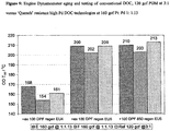
- FIG. 9 compares the dyno aging and testing performance of the commercial DOC 120 gcf @ 3:1 versus two further layered DOC technologies E and F.
- the samples were aged by standard DPF regeneration or by aggressive DPF regeneration (with 400° C. catalyst inlet and 850° C. catalyst bed temperature during post injection).
- the latter DOCs are equivalent with respect to PGM load and type (160 gcf @ 1:1.13), base metal components and base metal loads.
- the only difference in the latter parts is that the 2 layer system employed therein is reversed.
- catalyst F follows the new generation design i.e. more conventional Pt-Pd layer in the undercoat and a Pd-only (Pd-rich) layer in the overcoat, while in catalyst E the layers are reversed.
- the enhanced performance obtained with this new DOC design is possible with a range of Pt:Pd ratios.
- the Pt:Pd ratio of the undercoat is from about 20:1 to about 1:2 and the Pt:Pd ratio of the overcoat is from about 2:3 to about 0:1.
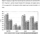
- catalysts G, H and J all offer competitive performance versus the commercial DOC reference, as shown in the dyno performance summary in FIG. 10 . It should be stressed that in all cases the performance is equal, or typically better, whilst offering PGM savings of 2.84, 2 and 4.88% respectively.
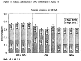
- FIG. 11 compares vehicle performance data for the DOC parts of FIG. 10 .
- This testing on a typical Euro 4 engine confirms the benefits seen on the dyno. All test parts offer equal, or better, activity with up >10% decrease in CO emissions seen for Catalysts G and H. In all cases the benefits are ascribed to superior EUDC performance i.e. better light-off and increased tolerance to quenching from HC poisons.
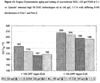
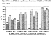
- FIG. 13 examines the potential for applying the second layer of the quench resistant DOC as a partial or zone pass. Additionally, it reports the performance for a series of parts wherein Pd is again 'thrifted' from the second pass and moved into the first. The data suggest that by zone coating, again in combination with the type of higher zeolite contents as employed in FIG. 13 , it becomes possible to increase the Pt:Pd ratio in the second layer (zone) without the adverse effects noted previously. Thus parts N, O and P display equivalent performance. Note no comparison is drawn here versus the reference since the PGM cost of the test parts is too high for meaningful comparison.
- FIG. 14 reports vehicle performance data for three DOCs tested after 70 h of post injection aging performed at a major OEM.
- the three DOCs comprise an internal OEM reference versus a conventional DOC 70 gcf @ 3:2 (catalyst Q) and zone coated quench resistant DOC also 70 gcf @ 3:2 (Catalyst R).
- the data show again a clear performance benefit for the new generation DOC which provides 79% CO and 86% HC conversion respectively over the NEDC cycle for a vehicle with comparatively cool engine out temperatures (average 150° C. for first 800 s) consistent with the enhanced light-off and decreased 'quenching' of the new generation design.
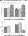
- FIGS. 15A /B and 16A/B show the SGB performance data after increasingly severe hydrothermal oven aging cycles for two commercial DOCs 150 gcf @ 4:1 versus the new generation DOC 210 @ 1:1.10. Samples were tested as cores 2.22 cm ⁇ 2.54 cm after aging at 700° C., 25 hours, 10% steam, air and 800° C., 25 hours, 10% steam, air. Two SGB test protocols were employed to fuirther differentiate the impact of HC concentration and speciation on performance.
- the first test conditions were selected to mimic a Euro V exhaust and comprised 1000 ppm CO, 600 ppm C1 n-Octane, 180 ppm C1 Methyl-Benzene, 75 ppm C1 Propene, 75 ppm C1 Methane, 80 ppm NO, 3 ppm SO 2 , 3.5% CO 2 , 13% O 2 , 3.5% H 2 O, balance N 2 and total flow 5 l/min with ramp from 50 to 300° C. at 10° C./min (hereafter complex HC mix test).
- the second set of test conditions were more typical 'SGB' conditions, employing only light HC species and comprised 350 ppm CO, 120 ppm H2, 90 ppm C1 propene, 180 ppm C1 propane, 2 ppm SO 2 , 270 ppm NO, 6% O 2 , 10.7% CO 2 , 3.5% H 2 O and balance N 2 and total flow 5 l/min with ramp from 100 to 400° C. at 15° C./min (hereafter C3 only HC mix test).
- FIG. 17 A further differentiation between conventional DOCs and the new generation technology may be found by comparing FIG. 17 and FIG. 18 wherein the effect Pt:Pd ratio on performance is examined.
- FIG. 17 the activity of commercial DOCs at equal PGM content but differing Pt:Pd ratio (120 @ 3:1 versus 120 @ 2:1) are shown.
- decreased Pt and increased Pd content correlates with increasing light-off temperatures and HC weaker oxidation performance.
- the 2:1 DOC also exhibits a more severe deactivation profile with the performance gap being increasingly large with harsher aging.
- the recovery of the technology after SOx aging is particularly weak. These trends are reflected in a comparison of HC performance.
- the DOC exhibits exactly the kind of weaknesses associated with increased Pd content in a conventional DOC design, as outlined in US2005/0045405 A1 .
- the performance data in FIG. 18 are in even more marked contrast.
- the fresh and 800 air/steam oven aged performance of three next generation quench resistant DOCs are compared.
- the performances of the 2:1 and 1:1 technologies, fresh and aged, and under conditions of low CO, high CO or high HC are within a few degrees. Indeed, after aging the light-off temperatures are within experimental error and likely reflect the intrinsic activity of the pass 1 washcoats and that the PGM content of the pass 2 is still sufficient to scavenge the transient toxic HC species believed to be responsible for inhibition of light-off.
- the performance of the 1:2 is somewhat weaker but after aging it is still quite competitive, particularly given that this technology represents a PGM saving of 35%.
- a catalytic device can comprise a housing disposed around a substrate with a compression ignition oxidation catalyst disposed at the substrate.
- the method for treating a compression ignition exhaust stream can comprise: introducing a diesel exhaust stream to a compression ignition oxidation catalyst; and oxidising an exhaust stream component.
- the catalyst materials are included in the formulation by combining alumina, or other appropriate support, with other catalyst materials to form a mixture, drying (actively or passively), and optionally calcining. More specifically, a slurry can be formed by combining alumina and water, and optionally pH control agents (such as inorganic or organic acids and bases) and/or other components.
- the catalytic materials e.g. catalytic metals, such as Pt
- This slurry can then be washcoated onto a suitable substrate.
- the washcoated product can be dried and heat treated to fix the washcoat onto the substrate.
- the catalyst can further comprise a zeolite.
- Possible zeolites include Y-type zeolite, beta ( ⁇ ) zeolite, ZSM-5, silica alumina phosphate (SAPO e.g. SAPO34) and the like, as well as combinations comprising at least one of the foregoing zeolites.
- SAPO silica alumina phosphate
- the zeolite can, for example, have a silica to alumina ratio (Si:Al) of about 25 to about 80, or, more specifically, about 35 to about 60. If the zeolite is employed, it can be added to the slurry along with the catalytic material (e.g., before the catalytic material has been calcined).
- This slurry can be dried and heat treated, e.g., at temperatures of about 500° C. to about 1,000°C., or more specifically about 500°C. to about 700°C., to form the finished catalyst formulation.
- the slurry can be washcoated onto the substrate and then heat treated as described above, to adjust the surface area and crystalline nature of the support.
- catalyst metals may optionally be disposed on the support. The catalyst metals, therefore, can be added after the washcoat is fixed onto the substrate by additional washcoat steps and/or by exposing the washcoated substrate to a liquid containing the catalytic metal.
- the supported catalyst comprises a PGM (Pt, Pd, Rh etc.) or more preferred a combination of PGMs, (modified) alumina, and zeolite, and optionally oxygen storage (OS) material.
- the amounts of these components in the catalyst can be: about 0.1 wt % to about 10 wt % PGM, about 50 wt % to about 80 wt % (modified) alumina, about 5 wt % to about 50 wt % OS, and about 10 wt % to about 50 wt % zeolite; or, more specifically, about 1 wt % to about 5 wt % PGM, about 40 wt % to about 60 wt % modified alumina, about 5 wt % to about 20 wt % of OS, and about 20 wt % to about 40 wt % zeolite.
- the supported catalyst can be disposed on a substrate.
- the substrate can comprise any material designed for use in the desired environment, e.g., a compression ignition engine (e.g., a diesel engine) environment.
- a compression ignition engine e.g., a diesel engine
- Some possible materials include cordierite, silicon carbide, metal, metal oxides (e.g., alumina, and the like), glasses, and the like, and mixtures comprising at least one of the foregoing materials.
- These materials can be in the form of packing material, extrudates, foils, perform, mat, fibrous material, monoliths (e.g., a honeycomb structure, and the like), other porous structures (e.g., porous glasses, sponges), foams, molecular sieves, and the like (depending upon the particular device), and combinations comprising at least one of the foregoing materials and forms, e.g., metallic foils, open pore alumina sponges, and porous ultra-low expansion glasses.
- these substrates can be coated with oxides and/or hexaaluminates, such as stainless steel foil coated with a hexaaluminate scale.
- the substrate can have any size or geometry, the size and geometry are preferably chosen to optimise geometric area in the given exhaust emission control device design parameters.
- the substrate has a honeycomb geometry, with the combs through-channel having any multi-sided or rounded shape, with substantially square, triangular, pentagonal, hexagonal, heptagonal, or octagonal or similar geometries preferred due to ease of manufacturing and increased surface area.
- the substrate can be disposed in a housing to form the converter.
- the housing can have any design and comprise any material suitable for the application. Suitable materials for the housing can comprise metals, alloys, and the like, such as ferritic stainless steels (including stainless steels such as, e.g., the 400-Series such as SS-409, SS-439, and SS-441), and other alloys (e.g. those containing nickel, chromium, aluminium, yttrium and the like, e.g., to permit increased stability and/or corrosion resistance at operating temperatures or under oxidising or reducing atmospheres).
- ferritic stainless steels including stainless steels such as, e.g., the 400-Series such as SS-409, SS-439, and SS-441
- other alloys e.g. those containing nickel, chromium, aluminium, yttrium and the like, e.g., to permit increased stability and/or corrosion resistance at operating temperatures or under oxidising or
- end cone(s), end plate(s), exhaust manifold cover(s), and the like can be concentrically fitted about the one or both ends and secured to the housing to provide a gas tight seal.
- These components can be formed separately (e.g., moulded or the like), or can be formed integrally with the housing using methods such as, e.g., a spin forming, or the like.
- the retention material Disposed between the housing and the substrate can be a retention material.
- the retention material which may be in the form of a mat, particulates, or the like, may be an intumescent material e.g., a material that comprises vermiculite component, i.e., a component that expands upon the application of heat, a non-intumescent material, or a combination thereof.
- intumescent material e.g., a material that comprises vermiculite component, i.e., a component that expands upon the application of heat
- non-intumescent material a non-intumescent material
- These materials may comprise ceramic materials e.g., ceramic fibres and other materials such as organic and inorganic binders and the like, or combinations comprising at least one of the foregoing materials.
- the coated monolith containing the high Pd-content layered DOC is incorporated into the exhaust flow of the compression ignition engine.
- This provides a means for treating said compression ignition exhaust stream to reduce the concentrations of environmental toxins by passing said diesel exhaust stream over the aforementioned compression ignition oxidation catalyst under net oxidising conditions (oxygen rich) to facilitate catalytic conversion/oxidation into more environmentally benign products.
- Part A The procedure for making Part A, is as follows: Slurry Alumina at pH ca. 4.5 and mill to d50 (diameter of 50% of the particles) of 4 ⁇ 0.5 microns, confirm d90. Add required ⁇ 40 as powder, correct for loss on ignition (LOI), to slurry. Re-mill combined slurry to maintain d50, if required. Next take the required concentration of Pt nitrate solution and slowly dilute with appropriate rheology modifier as required prior to adding solution dropwise to milled slurry. Slurry must be at a pH lower than 6.0 prior to metal addition and during Pt addition, monitor pH and prevent slurry from going to pH values below 3.0 with the judicious use of base.
- LOI loss on ignition
- the procedure for making Part B entails the following: Slurry SCFA-90 at pH ca. 4.5 and mill to d50 of 4 ⁇ 0.5 microns, confirm d90. Next take the required concentration of Pt nitrate solution and slowly dilute with appropriate rheology modifier as required prior to adding solution dropwise to slurry. Slurry must be at a pH lower than 6.0 prior to metal addition and during Pt addition, monitor pH and prevent pH from going to values below 3.0 with the judicious use of base. After metal addition, adjust to 3.5 with base and stir slurry for two hours. Next add the required concentration of Pd Nitrate solution dropwise, again during metal addition, monitor pH and prevent slurry from going to pH values below 3.0 with the judicious use of base.
- Part C The procedure for making Part C, as employed as a test technology is as follows: Slurry Alumina at pH ca. 4.5 and mill to d50 of 4 ⁇ 0.5 microns, confirm d90. Add the ⁇ 40 powder, correct for LOI, with minimal D.I. water to maintain slurry rheology and viscosity. Lightly mill resultant slurry to maintain d50, d90, d100, as required. Next take the required concentration of Pt nitrate solution and slowly dilute with appropriate rheology modifier as required prior to adding solution dropwise to milled Alumina slurry.
- Slurry must be at a pH lower than 6.0 prior to metal addition and during Pt addition, monitor pH and prevent slurry from going to pH values below 3.0 with the judicious use of base. After metal addition, adjust to 3.5 with base and stir slurry for two hours. Next add the required concentration of Pd Nitrate solution dropwise, again during metal addition, monitor pH and prevent slurry from going to pH values below 3.0 with the judicious use of base. Stir resultant mixture for one hour to allow for fall chemisorption of metal. Then coat monolith in 1 pass and calcine at temperatures ⁇ 540° C. for ⁇ 1 hour. Pass 2: Add Barium salt to deionised water and required rheology pH modifiers and mix.
- the procedure for making Part G is as follows: Slurry Alumina at pH of 3.5-5 and mill to d50 of ⁇ 10.5 microns, confirm d90. Add the ⁇ 40 powder, correct for LOI, with minimal D.I. water to maintain slurry rheology and viscosity. Lightly mill resultant slurry to maintain d50, d90, d100, as required. Take the required concentration of Pt nitrate and dilute with appropriate rheology modifier as required prior to adding dropwise to milled Alumina slurry. Slurry must be at a pH ⁇ 6.0 prior to metal add and during Pt addition, monitor pH and prevent slurry from going to pH values below 3.0 with the judicious use of base.
- Part R The procedure for making Part R, as submitted in OEM test trials: First prepare the 'white' washcoat master batch i.e. complete batching of metal oxide components. Add HP14/150 Zr Alumina, with constant mixing, at 15 ⁇ T ⁇ 25° C. to deionised water containing any required rheology and pH modifiers to maintain pH of 4.5 and a smooth flowing slurry. During the addition it may be necessary to begin milling to ensure slurry maintains free flowing characteristics. Mill to d50 of 6-8 microns, d90 of 20-25 and 100% pass ⁇ 60 microns. Add ⁇ 40 powder, correct for LOI, with minimal D.I. water to maintain slurry rheology and viscosity.
- Slurry must be at a pH lower than 6.0 prior to metal addition and during Pt addition, monitor pH and prevent slurry from going to pH values below 3.0 with the judicious use of base. After metal addition, adjust to a pH of 3.5 with base and stir slurry for two hours. Examine d50, d90 and d100 to confirm no agglomeration of PGM has occurred. Next add the required concentration of Pd Nitrate solution dropwise, again during metal addition, monitor pH and prevent slurry from going to pH values below 3.0 with the judicious use of base. Stir resultant mixture for three hours to allow full chemisorption of metal. Re-confirm d50, d90, d100. Adjust pH of slurry to 3-3.5 and coat monolith in 1 pass using appropriate piston or other metered charge coater along 75% of length of part and calcine at temperatures ⁇ 540° C. for ⁇ 1 hour.
- Parts X, Y and Z as employed as test technologies is as follows: First prepare the 'white' washcoat master batch i.e. complete batching of metal oxide components. Add alumina, with constant mixing, at 15 ⁇ T ⁇ 25° C. to deionised water containing any required rheology and pH modifiers to maintain pH of 4.5. Mill to d50 of 6-8 microns, d90 of 20-25 and 100% pass ⁇ 60 microns. Add the ⁇ 40 powder, correct for LOI, with minimal D.I. water to maintain slurry rheology and viscosity. Lightly mill resultant slurry to maintain d50, d90 and d100, as required. Split slurry into two batches for pass 1 and 2.
Landscapes
- Chemical & Material Sciences (AREA)
- Engineering & Computer Science (AREA)
- Chemical Kinetics & Catalysis (AREA)
- Materials Engineering (AREA)
- Organic Chemistry (AREA)
- Combustion & Propulsion (AREA)
- Health & Medical Sciences (AREA)
- Mechanical Engineering (AREA)
- Oil, Petroleum & Natural Gas (AREA)
- General Chemical & Material Sciences (AREA)
- Analytical Chemistry (AREA)
- Toxicology (AREA)
- General Engineering & Computer Science (AREA)
- Environmental & Geological Engineering (AREA)
- Biomedical Technology (AREA)
- Catalysts (AREA)
- Exhaust Gas After Treatment (AREA)
- Exhaust Gas Treatment By Means Of Catalyst (AREA)
Abstract
Description
- The exhaust emissions from motor vehicles are a well known and significant source of air pollution. The most significant gaseous vehicular emissions comprise pollutants such as carbon monoxide (CO), oxides of nitrogen (NO and NO2 collectively NOx), and unburnt hydrocarbons (HC). In addition to the gaseous components, the diesel exhaust stream also contains entrained solids, commonly referred to as particulate matter or soot, upon which may additionally be adsorbed volatile/soluble organic fraction (SOF). The gaseous pollutants have been demonstrated to be major contributors to the photochemical smog and ozone events which have been correlated to significant adverse impacts on human health (M. V. Twigg, Applied Catalysis B, vol. 70, (2007), p 2-25). Additionally, soot and its associated SOF content present a further health risk as its small size makes this potentially carcinogenic material respirable. Hence increasingly stringent legislative limits have been introduced in order to regulate the emissions from both gasoline and diesel internal combustion engines e.g. Euro 5 or Euro 6, Regulation (EC) No 715/2007 of the European Parliament and of the Council, 20 Jun. 2007, Official Journal of the
European Union L 171/1, see also Twigg, Applied Catalysis B, vol. 70 p 2-25 and R. M. Heck, R. J. Farrauto Applied Catalysis A vol. 221, (2001), p 443-457 and references therein. - An advantage of diesel/compression ignition engines is their inherent lean burn operation, i.e. combustion occurs due to fuel compression under conditions of excess O2, which results in increased fuel economy and decreased emissions (in g/km) of CO, HC and CO2 cf. the stoichiometric gasoline engine. Moreover, diesel engines offer increased durability and are able to provide high torque at low engine rpm and these attractive characteristics have helped diesel passenger cars gain a >50% market share in the Western Europe market. However, despite the inherent advantages offered by lean mode combustion conventional diesel engines still do not meet the aforementioned legislative targets and thus a range of exhaust after-treatment technologies have been developed to address this requirement. These technologies include, but are not limited to, engine control methodologies/modification, alternate combustion cycles and the use of after-treatment systems e.g. catalytic control devices which eliminate exhaust pollutants by promoting chemical changes to convert unwanted compounds into more benign species. In the case of diesel/compression ignition engines the latter devices include the Diesel Oxidation Catalyst (DOC), Diesel NOx Trap/NOx Storage Catalyst (DNT/NSC) and Selective Catalytic Reduction catalyst (SCR) to address emissions of CO, HC (DOC) and NOx and the use of the Catalysed Diesel Particulate Filter (CDPF) for the removal and combustion of entrained solids, commonly referred to as particulate matter or soot.
- Of the various catalytic emission reduction systems for diesel emission control listed above, the DOC is both the most widely studied and implemented technology, for examples see
U.S. Pat. No. 5,371,056 ,U.S. Pat. No. 5,462,907 ,U.S. Pat. No. 6,153,160 ,U.S. Pat. No. 6,274,107 , J. A. A. van den Tillaart, J. Leyrer, S. Eckhoff and E. S. Lox in Applied Catalysis B vol. 10, 1-3, p 53-68 (1996). The design of these systems and materials employed therein are somewhat generic and typically consist of a refractory oxide support e.g. an (modified) alumina, a hydrocarbon storage/release component and an active Precious Group Metal (PGM) to catalyse the oxidative conversion of the pollutants into more benign products (H2O and CO2). - The use of the HC storage/release component, conventionally a microporous crystalline aluminosilicate also known as a Zeolite or molecular sieve, is employed to prevent low temperature HC poisoning of the PGM centres (see Applied Catalysis B, vol. 70, (2007), , Applied Catalysis A vol. 221, (2001), p 443). The introduction of the Zeolite in the DOC provides a mechanism for the low temperature condensative adsorption of a significant portion of the higher molecular weight unburnt HC species emitted during 'cold start' of the engine. This limits the potential for HC adsorption on active precious metal centres and their resultant poisoning by 'site-blocking'. As the exhaust gas temperature increases the retained HC species are 'released' by evaporation and diffusion out of the porous structure of the Zeolite but only at temperatures where the PGM is fully active and capable of combusting the plume of released species (see
U.S. Pat. No. 2,125,231 ). - The choice of metal(s) in the DOC is based upon their ability to offer the highest turnover frequency (number of reactions per second) with respect to the oxidation of CO and Hydrocarbon to CO2 and H2O at low temperatures and low concentrations of active component within the DOC formulation. Initially Pt (e.g.
U.S. Pat. No. 5,627,124 ) or more recently the combination of Pt and Pd has been employed as the primary catalytic species (e.g.US2008/0045405 A1 , U. Neuhausen, K. V. Klementiev, F.-W. Schütze, G. Miehe, H. Fuess and E. S. Lox in Applied Catalysis B: Environmental, vol. 60, 3-4, (2005), p 191-199 and references therein). - However, the operational requirements of the DOC with respect to conversion of gaseous emissions have been augmented over time to meet specific new challenges arising from successive generations of legalisation, e.g. the ability to efficiently combust post-injected HCs to generate the thermal 'bloom' required to initiate DPF regeneration or more recently the ability to oxidize NO to NO2 in order to facilitate low temperature NH3-SCR chemistry. Moreover, this extensive multi-functionality must be realised without detrimental impact to the primary role of the DOC for effective emission control i.e. the DOC must possess a low temperature 'light off'. Thus, in addition to such multi-functionality the DOC must provide operation at low temperatures to minimise 'cold-start' emissions. This requirement is especially critical given the increasingly lower temperature window of operation of the current and next generation diesel engines, which present increasing CO and HC emissions arising from the increased use of exhaust gas recirculation or advanced combustion cycles employed to decrease engine out NOx levels (e.g.
WO/2005/031132 , Method and Apparatus for Providing for High EGR Gaseous-Fueled Direct Injection Internal Combustion Engine). - These multiple challenges are rendered yet more difficult due to the intrinsic process of CO oxidation. The catalytic conversion of this pollutant is known to follow a negative order kinetic response, i.e. higher concentrations of CO are self-inhibitory to the rate of oxidation (see A. Bourane and D. Bianchi J. Catalysis 222 (2004) 499-510 and references therein). Moreover, during reaction there is competition for adsorption centres on the active PGM between CO, NO, HC and O2, with the adsorption of HC being particularly problematic as this acts as a poison to low temperature operation, necessitating the inclusion of the aforementioned zeolite component to address this issue. Hence as engine out concentrations of CO and HC increase and engine out temperatures decrease the challenge for effective operation of the catalyst to fulfil legislative requirements becomes increasingly difficult. A further and final requirement is that the DOC must maintain high levels of activity through end-of-life. This is a stringent requirement given the DOC is exposed to transients of extreme temperatures in the presence of steam e.g. for the operation of a close-coupled catalyst (to minimize light-off time) or during the active regeneration strategy required for the DPF. The latter case is especially challenging since there is an in-catalyst exotherm and steam generated by the combustion of post-injected hydrocarbons specifically located at the dispersed PGM sites. Such processes are known to result in catastrophic sintering (PGM particle coalescence), particularly for Pt (see M. Chen, L. D. Schmidt, J. Catal. 56 (1979) 198). This has resulted in the aforementioned introduction of Pt/Pd bi-metallic DOCs with a primary role of Pd to inhibit the rate of Pt sintering (Lox et al. Applied Catalysis B: Environmental, vol. 60, 3-4, (2005), p 191).
- However, despite these many developments, it has still been necessary to increase the PGM content of conventional DOCs in order to fulfil the emission targets for end-of-life performance. This in turn has increased demand for Platinum (Pt) and Palladium (Pd) resulting in price pressure for these PGMs and a resultant impact on the cost of emissions aftertreatment systems for the vehicle manufacturers and end customer. The relative costs of Pt versus Pd (average price Jan. 1, 2008 through Jan. 1, 2009 was 1535 US dollars and 342 US dollars respectively) means there is a continuing incentive to enable the use of higher Pd, lower Pt content DOC technologies as a means of decreasing total system cost. However, to date, practical limitations have been encountered regarding the usage of lower Pt:Pd ratios. While Pd is effective at enhancing the stability of PGM dispersion it has been found that there appears to be a practical limit beyond which CO and HC oxidation performance are below the levels required to fulfil emissions targets (
US2008/0045405 A1 ). Additionally, it is known that Pd enhances the sulfur sensitivity i.e. poisoning of the DOC, resulting in retardation of catalyst light-off (see, The Impact of Sulfur in Diesel Fuel on Catalyst Emission Control Technology-MECA white paper Mar. 15, 1999 and references therein at www.meca.org). Finally, Pd has also been found to inhibit the oxidation of both paraffins and NO, the former issue resulting in increased tailpipe HC, while the inhibition of NO2 generation is linked to decreased performance for both CDPF and urea-SCR systems (US2008/0045405 A1 ). - Hence what is required in the art is a method or technology to enable the use of high Pd content, more cost effective, diesel oxidation catalysts to replace conventional high Pt content technologies. These high Pd DOCs must offer competitive fresh, de-greened, hydrothermally durable and poison resistant activity under the diverse conditions of the diesel exhaust environment while enabling superior performance at equal metal cost or equal performance at decreased cost. Additionally they must provide the aforementioned improvements whilst retaining high NO and HC oxidation functionality as required in modern multi-brick emission control architectures.
- The invention disclosed herein describes a new class of layered and zoned DOC systems capable of addressing the challenges and requirements outlined previously. Thus, we demonstrate, in a surprising and novel discovery, the successful application of Pd-rich DOCs for the conversion of CO and HC under fuel-lean conditions. This new class of Pd-rich DOCs provides both high activity but also enhanced hydrothermal durability, especially with regards to the cycle post-injection DPF regeneration cycles typical of modern vehicular applications, as compared to conventional DOC technologies. These benefits are realised by the combination of functionalised layers to introduce the capability of the DOC to resist 'quenching' i.e. transient active site blocking arising from (especially) HC or CO under lower temperatures i.e. 'cold start' conditions. Thus, the use of 'quench' tolerant overcoat with a second dedicated oxidation layer, which itself may also be Pd rich, provides a synergy which enables high conversion of pollutants at lower temperatures and with increased hydrothermal durability.
- In another embodiment, the present invention describes a method for removal of gaseous pollutants from the exhaust stream of a diesel/compression ignition engine. This is achieved by contacting the exhaust stream with the novel catalyst described herein, where the catalyst comprises a novel washcoat design comprising two functionalised layers which enable high catalytic performance over a range of PGM contents and ratios of Pt:Pd, including technologies enriched in Pd content.
- More particularly, the present invention provides an oxidation catalyst, for the remediation of pollutants from the exhaust of a compression ignition comprising a carrier or substrate upon which is disposed at least two layers of washcoat wherein:
- a. the first layer or undercoat layer comprises a refractory oxide support, optionally a zeolite, optionally an oxygen storage material and a primary catalyic metal selected from the group consisting of platinum, palladium, iridium, rhodium, ruthenium, alloys thereof, and mixtures thereof
- b. a second layer or overcoat layer comprises a refractory oxide support, optionally a zeolite, optionally an oxygen storage material and a primary catalytic metal selected from the group consisting of platinum, palladium, iridium, rhodium, ruthenium, alloys, thereof, and mixtures thereof,
- c. a catalyst substantially enriched in Pd content and particularly wherein the Pd to Pt ratio of the overcoat layer is greater than the Pd to Pt ratio of the undercoat. Preferably the Pt:Pd ratio of the undercoat is from about 20:1 to about 1:2, the Pt:Pd ratio of the overcoat is from about 2:3 to about 0:1 e.g. a Pt-free, Pd-only layer.
- In a preferred embodiment, the Pt:Pd ratio of the undercoat is about 1:1 and the Pt:Pd ratio of the overcoat is about 1:2. The overcoat may optionally contain salts or oxides of barium or lantherium.
- In a preferred embodiment, the refractory oxide support in the undercoat and/or the overcoat is alumina, a modified or heteroatom doped alumina, zirconia or titania or combinations thereof. The heteroatom dopant can be Si, Fe, Zr, Ba or La or combinations thereof.
- The optional zeolite in the undercoat and/or overcoat is selected from the group Beta (i), Chabazite, Clinoptilolite, Faujastie, Ferrierite, Mordenite, Offretite, Silicalite, zeolite X, zeolite Y, ultrastable zeolite Y, ZSM5, ZSM11, ZSM22 or other ZSM series material or structural isomorphs thereof, e.g. SAPO34 or mixtures thereof.
- The catalyst device of the invention has an inlet and an outlet and, and the overcoat is optionally applied to cover a length of about 5% to about 75% from the inlet, and the undercoat is applied to cover a length of about 95% to about 25% from the inlet.
- Another aspect of the invention relates to a diesel oxidation catalyst wherein the catalyst has an inlet and an outlet, wherein a washcoat zone is applied to cover a length of about 25% to about 95% from the inlet and the washcoat contains Pt:Pd at a ratio of about 2:3 to about 0:1 and a second washcoat zone is optionally applied to cover a length of about 5% to about 75% from the outlet and the washcoat contains Pt:Pd at a ratio of about 2:1 to about 1:2.
- A still further aspect of the invention relates to a method of treating exhaust gas comprising passing an exhaust gas over a catalytic device, comprising: a housing disposed around a substrate; an oxidation catalyst, for the remediation of pollutants from the exhaust of a compression ignition comprising a carrier or substrate upon which is disposed at least two layers of washcoat wherein:
- a. the first layer or undercoat layer comprises a refractory oxide support, optionally a zeolite, optionally an oxygen storage material and primary catalytic metal(s) selected form the group of Precious Group Metals consisting of platinum, palladium, iridium, rhodium, ruthenium, alloys thereof, and combinations thereof;
- b. a second layer or overcoat layer comprises a refractory oxide support, optionally a zeolite, optionally an oxygen storage material and primary catalytic metal(s) selected from the group of Precious Group Metals consisting of platinum, palladium, iridium, rhodium, ruthenium, alloys thereof, and combinations thereof;
- c. a catalyst substantially enriched in Pd content and particularly wherein the Pd to Pt ratio of the overcoat is greater than that of the undercoat.
- The catalytic device of the invention further includes a retention material disposed between the housing and the substrate.
- Benefits and features include:
- a) Provision for a DOC to promote lower temperature oxidation of CO and HC.
- b) Provision for a DOC with improved hydrothermal durability, especially with regards to light-off after aggressive post-injection/CDPF regeneration cycles.
- c) Provision for a DOC able to employ high Pd contents without negative impact on activity, as is noted for conventional DOC designs. This offers the possibility of either cost savings or performance benefits as is appropriate for the specific application.
- d) The ability to employ layered and zoned technologies to optimise primary CO and HC oxidation performance without loss in secondary performance characteristic e.g. the use of a Pd-rich/Pd-only overcoat layer or zone with a more Pt-rich undercoat pass to provide increased CO and HC oxidation function whilst maintaining high NO oxidation to NO2 to enable high NH3-SCR activity for NOx reduction or NO2 catalysed soot oxidation for a downstream CDPF.
- e) Provision for a DOC with a second layer or zone rich in Pd such that the high Pd content provides increased HC oxidation function for post-injected HCs for CDPF regeneration with decreased thermal deactivation or sintering of the PGM dispersion.
- This strategy contrasts with that employed in the conventional single layer DOC systems wherein there is a more mono-modal description of the active site and this sole type of active site is expected to provide a multiplicity of functions. Moreover, in the conventional DOC design it is not predicted that 'quenching' will occur and hence no specific designs are employed therein to address this fundamental limitation and inhibition in performance.
-
-
FIG. 1 shows the effect of a Propene/Propane mix (120 ppm C1) on the CO light-off (T50) for conventional PtPd DOC, 120 gcf PGM @ 3:1, in SGB testing. -
FIG. 2 compares the light-off and quench/light-down performance forconventional PtPd DOC 120 gcf @ 3:1 in SGB testing. -
FIG. 3 shows the impact of CO or HC pulses on the isothermal activity at 170, 160 and 150° C. forconventional PtPd DOC 120 gcf @ 3:1. -
FIG. 4 shows the light-off and light-down for next generation Catalyst A. -
FIG. 5 compares the light-off and light-down for theconventional PtPd DOC 120 gcf @ 3:1, and three next generation 'quench' resistant DOC technologies A, B, and C. -
FIG. 6 illustrates the impact of CO or HC pulses on the isothermal activity at 170, 160 and 150° C. for next generation 'quench' resistant DOC Catalyst B. -
FIG. 7 shows the impact of CO or HC pulses on the isothermal activity at 170, 160 and 150° C. for next generation 'quench' resistant DOC Catalyst C. -
FIG. 8 summarizes engine dynamometer aging and testing of conventional DOC, 120 gcf PGM at 3:1 versus 'quench' resistant DOC technologies at 160 gcf Pt:Pd 1:1.13. -
FIG. 9 illustrates engine dynamometer aging and testing of conventional DOC, 120 gcf PGM at 3:1 versus 'quench' resistant DOC technologies at 160 gcf Pt:Pd 1:1.13. -
FIG. 10 compares the engine dynamometer aging and testing of conventional DOC, 120 gcf PGM at 3:1 vs 'quench' resistant DOC technologies at differing PGM content and Pt:Pd ratios (G is 160 @ 1:1.13, H is 143 @ 1.3:1 and J is 183 @ 1:1.77). -
FIG. 11 shows the vehicle performance of the DOC technologies exFIG. 10 . -
FIG. 12 compares the dyno aging/testing of a conventional DOC-120 @ 3:1 vs 'quench' resistant DOCs (160 @ 1:1.13) with differing Pt:Pd distributions inPass -
FIG. 13 contrasts the dyno testing of a conventional DOC, 120 gcf PGM at 3:1vs 50% zoned coated 'quench' resistant DOCs at 154 gcf @ 4:3 (1.3:1). -
FIG. 14 summarizes the vehicle performance of an OEM DOC versus onecommercial DOC 70 gcf @ 3/2 versus a zone-coated quenchresistant DOC 70 gcf @ 3/2. -
FIGS. 15A and B show the SGB testing/oven aging data for a conventional DOC, 150 gcf PGM @ 4:1 vs 'quench' resistant DOC, 210 gcf PGM @ 1:1.1 using complex HC mix. -
FIGS. 16A and B show the SGB testing/oven aging data for a conventional DOC, 150 @ 4:1 vs 'quench' resistant DOC, 210 gcf PGM @ 1:1.1 using C3 only HC mix. -
FIG. 17 illustrates the impact of Pt:Pd ratio on performance of conventional DOC, 120 gcf PGM at 3:1 versus 120 gcf @ 2:1 Pt:Pd. -
FIG. 18 shows the impact of Pt:Pd ratio for 120 gcf (2:1, 1:1 and 1:2) on the performance of a quench resistant DOC fresh and aged (oven 800° C., 25 h, 10% steam air). - The present invention relates to the development and use of novel high Pd content diesel oxidation catalyst (DOC) for emission aftertreatment catalysis. This is made possible by the development of a specific layered or zoned strategy, wherein the distinct layers afford specific functionalities to the catalyst and work in concert to provide an effective synergy for overall improvements in performance and durability. Thus, the design herein employs a more conventional undercoat (pass 1) to facilitate the required CO, HC and NO oxidation reactions and a second layer or zone (pass 2), which is enriched in Pd or indeed Pd-only, which has been developed to provide the catalyst with a characteristic dubbed 'quench' tolerance. This enables the lower temperature light-off of the undercoat (pass 1) as well as enhancing the hydrothermal durability of the DOC, especially to post injection (DPF regeneration) aging cycles due to the ability of the Pd-rich/Pd-only overcoat to facilitate high rates of oxidation of post-injected HC, thereby decreasing the exothermal stress in the more conventional undercoat formulation. Both layers comprise typical base metal components e.g. alumina (or other suitable refractory oxide e.g. ZrO2, TiO2), zeolite for bulk HC storage/release and optionally an oxygen storage material based upon CeZrOx. Typical aluminas that may be employed in this invention include γ-Al2O3, δ-Al2O3, θ-Al2O3, or other transition alumina. Additionally, the alumina could be modified e.g. by the inclusion of heteroatom species with cationic doping by Si, Fe, Zr, Ba or La preferred. However, notwithstanding these modifications the novel invention herein is not related to specific material development but rather to the demonstration of a previously less well understood transient deactivation mechanism and a means to overcome this limitation and thus gain significant improvements in the activity and hydrothermal durability of DOCs and especially Pd-rich DOCs.
- The concept of quench tolerance is proposed, without wishing to be bound by theory, to be based upon the transient active site blocking of PGM sites by 'toxic' HC species in the exhaust. While the idea of HC poisoning is well known it has been previously believed that the presence of zeolite in the DOC washcoat was sufficient to address this issue (Applied Catalysis B, vol. 70, (2007), , Applied Catalysis A vol. 221, (2001), p 443,
U.S. Pat. No. 2,125,231 ). The data herein however contradict this assertion (see hereafter). Indeed, it is noted that 'quenching'/active site blocking by specific HCs may still occur at low temperatures even for zeolite-containing DOCs since the zeolite is only capable of interacting with a limited range of hydrocarbons. There are two fundamental limits which determine this range. Firstly, is the limit imposed by so-called 'shape selectivity'. All zeolites have well defined channel and/or cage structures arising from the combination of primary building units (repeating structures derived from the assemblages of TO4 tetrahedra, where T is Si or Al) e.g. for MFI zeolites the primary building unit is the 5-1 ring structure (see http://www.iza-structure.org/databases for further details). As stated the combination of these primary building units gives rise to the secondary order within the zeolite and thus enforces limits upon the maximum size of species which may enter the structure, i.e. provides the 'molecular sieve' function. For zeolite β, the structure contains two 12 ring structures, one a regular ring of 5.6 by 5.6 Å and a second more irregular ring of ca. 7.7 by 6.6 Å (at maximum and minimum), and hence molecules with diameters (so-called critical diameters) larger than this are excluded and thus the zeolite cannot prevent adsorption of such large HCs e.g. poly-substituted aromatics or poly-aromatic species on active PGM sites. Secondly, the ability of a conventional proton zeolite to trap light hydrocarbons i.e. permanent gas HCs e.g. CH4, C2, C3, C4 species etc., is negligible as such species will not undergo the conventional condensative adsorption within the pore structure. Hence a second class of potentially toxic HC species, specifically unsaturated SP<2 >and SP hybridised HCs, can diffuse rapidly through the zeolite and washcoat in general until they come into contact with the active PGM sites whereupon they are strongly chemisorbed, again resulting in transient site blocking/quenching. Moreover, it should be noted that the primary use of zeolites in the petrochemical industry is as cracking catalysts i.e. to promote the conversion of long-chain HCs into short chain, typically unsaturated, species (e.g.U.S. Pat. No. 4,740,292 ). Thus the use of zeolites themselves can also generate in-situ, the kinds of toxic short chain alkenes/alkynes which can subsequently poison the PGM function of the DOC. - In order to circumvent the low temperature transient deactivation of the DOC by toxic HCs a new design strategy has been developed and implemented. Herein a layered or zoned formulation is introduced. A minimum of two layers or zones are applied consecutively to the monolithic substrate or carrier, each layer providing specific functionality and in combination a direct synergy. The first layer/pass/zone applied to the substrate, hereafter the undercoat, comprises a refractory oxide support e.g. (modified/doped) alumina, zirconia etc. and optionally a zeolite and also optionally an OS material. In addition the undercoat is characterised by possessing Pt and optionally Pd at a ratio of about Pt:Pd 20:1 to about 1:2. It should be noted that the high degree of flexibility in Pt:Pd ratio is enabled by use of the second layer/zone, hereafter overcoat. This overcoat again comprises a refractory oxide support e.g. (modified/doped) alumina, zirconia, titania etc. and optionally a zeolite and also optionally an OS material. Indeed, to simplify the manufacturing scheme of this new class of DOCs, the base metal oxide components of the undercoat and overcoat may be identical. This enables production of a 'white' washcoat which is split into two batches prior to coating and the appropriate PGM loads and ratios added individually. As indicated by the preceding statement, the overcoat also contains precious metal, but in this instance the washcoat is enriched in Pd such that the ratio of Pt:Pd is about 0:1 (i.e. Pd-only) to about 2:3. This strategy is contra to the teachings in
US 2005/0045405 A1 wherein a layered design is also employed but this design is based upon a Pt-enriched overcoat and Pd-enriched undercoat. Additionally,US 2005/0045405 A1 stresses the importance of avoiding Pd migration to the overcoat and that it is necessary to omit zeolite (HC storage component) from the undercoat, neither of these teachings are consistent with the current invention. Moreover, this design is intended to maximise NO2 production rather than provide optimised CO, HC and NO oxidation function. Further differentiation will be drawn in the following examples. - Thus the following examples contained herein shall describe and differentiate a next generation novel DOC design. The novel oxidation catalyst described herein is intended for the remediation of pollutants from the exhaust of a compression ignition engine. It comprises a carrier or substrate upon which is disposed at least two layers of washcoat wherein at least both layers comprise a refractory oxide support (alumina, heteroatom doped alumina e.g. Si, Fe, Zr, Ba or La, or zirconia as ZrO2, titania etc.), optionally a zeolite e.g. Beta (β), Chabazite, Clinoptilolite, Faujasite, Ferrierite, Mordenite, Offretite, Silicalite, zeolite X, zeolite Y, Ultrastable zeolite Y, ZSM5, ZSM11, ZSM22 or other ZSM series material or structural isomorphs thereof e.g. SAPO34 or mixtures thereof, optionally an oxygen storage material and primary catalytic metal(s) selected from the group of Precious Group Metals consisting of platinum, palladium, iridium, rhodium, ruthenium, alloys thereof, and combinations thereof. The layers of the catalyst may contain different base metal components or indeed identical components but the two layers are especially differentiated in that the second layer (overcoat) is substantially enriched in Pd content and particularly wherein the Pd to Pt ratio of the overcoat is greater than that of the undercoat. For example the Pt:Pd ratio of the undercoat is from about 20:1 to about 1:2 while the Pt:Pd ratio of the overcoat is from about 2:3 to about 0:1 i.e. a Pt-free, Pd-only layer. In a further illustrative example the catalyst may contain two layers wherein the Pt:Pd ratio of the undercoat is about 1:1 and the Pt:Pd ratio of the overcoat is about 1:2. Optionally the overcoat may additionally contain Rhodium. The overcoat may additionally be modified by the inclusion of salts or oxides of Barium and Lanthanum. Moreover, the layers of the catalyst may also be expressed as zones e.g. wherein the catalyst has an inlet and an outlet, and the overcoat is applied to cover a length of about 5% to about 75% from the inlet. Similarly, wherein the catalyst has an inlet and an outlet, and the undercoat is applied to cover a length of about 95% to about 25% from the inlet.
-
FIG. 1 illustrates the Synthetic Gas Bench (SGB) performance data for a commercial Pt-Pd DOC (120 gram per cubic foot, hereafter gcf @ 3Pt:1Pd) after aging/stabilisation at 650° C. in steam/air for 20 h. The data contrasts the CO light-off temperatures (T50) at 400, 800 or 1200 ppm CO in the presence or absence of 150 ppm C1 propene/propane (3:1) (12% O2, 150 ppm NO, 5% CO2, 5% H2O, balance N2 at a total flow of 30 l/min, ramp 75-325° C. at 15° C./min). The impact of the HC on performance is clear and unambiguous. In the absence of HC, performance is negatively correlated, i.e. the light-off temperature exhibits an inverse correlation with respect to CO concentration, in agreement with extensive studies regarding CO oxidation which repeatedly show CO oxidation is negative reaction order with respect to CO concentration e.g. A. Bourane and D. Bianchi J. Catalysis 222 (2004) 499-510. However, in the presence of small amounts of gaseous propene/propane, the response of the catalyst is completely divergent. In this instance the T50s are increased by 15-50° C. but more significantly they are all equal within the experimental error of the test i.e. the performance of the catalyst is independent of CO concentration but is rather dictated by an external phenomenon linked to the presence of the HC. It is proposed that this phenomenon is a transient inhibition effect involving the preferential adsorption of propene on the active centres of the Pt-Pd required for O2 dissociative adsorption (the proposed rate limiting step in CO oxidation). This is consistent with the high sticking probability of propene on the high defect planes of PGM surfaces resulting in a site-blocking phenomenon which is only overcome at temperatures sufficient to facilitate oxidative desorption of the HC (R. Burch and P. J. Millington, Catalysis Today, Vol 26(2), 1995, p 185). Since this temperature is independent of CO concentration then catalyst light-off exhibits the independent activity trace inFIG. 1 . - The phenomenon of transient site blocking is further examined in
FIG. 2 which shows the full light-off (positive temperature ramp) and quench (negative temperature ramp/cooling cycle) for the commercial DOC ofFIG. 1 . Herein several salient features are evident. Firstly, during light-off, one notes conversion of HC prior to CO. Secondly, the light-off of CO is entirely coincident with HC. Finally, during the quench cycle low levels of HC conversion continue after CO oxidation decreases to 0%. These responses are entirely consistent with the mechanism proposed. Hence at low temperatures adsorption of propene results in the apparent conversion noted. The interaction of HC is of some importance since although the DOC contains zeolite/HC scavenger (β, SAR 40), it is apparent that the zeolite does not prevent HC poisoning by propene, for reasons explained previously. Thus, the propene passes through the washcoat unaffected until it comes in contact with the PGM centres whereupon it is chemisorbed, resulting in site-blocking. Then as the temperature increases the conversion and desorption of the chemisorbed HC begins and as each active site is 'cleaned' of the transient HC poison, the rate of O2 dissociative adsorption increases thereby further catalysing the oxidation of adsorbed HC and CO species, until light-off is achieved and the PGM surface is completely converted from a reduced (HC/CO covered) to a fully oxidised (O covered) condition. However, as the temperature is subsequently cooled and the rate of oxidation decreases i.e. under the quench cycle, then the exotherm of oxidation associated with the active PGM centres also decreases, thereby further decreasing the rates of all oxidative processes. This establishes a negative feedback loop until a critical temperature, dubbed Q50 (quench 50% conversion), is reached. Then the surface coverage again becomes dominated by CO and HC species and surface O content is low. Moreover, at this point competition for surface sites between O2, CO and propene is re-established, with the latter becoming increasingly favoured, hence apparent HC conversion continues when CO conversion is zero. -
FIG. 3 further examines the ability of CO and propene to 'quench' the catalytic oxidation function of the commercial DOC. This Figure contrasts the performance of the 120 gcf 3:1 DOC under isothermal conditions with transient pulses of either CO or HC viz. In the CO pulse test, the DOC is exposed to 12% O2, C3H6/C3H8 (3:1) @ 150 ppm C1, 150 ppm NO, 5% CO2, 5% H2O and N2 (30 l/min) plus 400 ppm CO, which is increased to 1200 ppm for 5 min to attempt to quench catalytic function. The pulse is repeated 3 times (5 min low CO, 5 min high CO) at 170° C., and then again at 160° C. and finally again at 150° C. Conversely in the HC pulse test a comparable gas mix, with CO at 400 ppm, is employed but herein HC is introduced at 150 ppm C1, or 450 ppm C1, again in 3 cycles and again at 170, 160 and 150° C. The responses for the tests inFIG. 3 again show significant differences. In the case of CO pulsing, the catalyst maintains 100% CO conversion at 170° C. under both low and high CO conditions but upon decreasing the temperature to 160° C. the catalyst is thermally deactivated and <20% conversion is seen for both low and high CO at 160 and 150° C., consistent with catalyst deactivation due to domination of the surface by HC and CO species. The bed temperature of the catalyst reflects the various processes. Thus, small increases in the bed exotherm are associated with the high CO pulses and as the catalyst deactivates the exotherm in the catalyst is seen to traverse from the front of the core to the rear (where the thermocouple was located) and hence immediately prior to complete deactivation an exotherm is recorded. In the case of the HC pulses a different response is noted. Thus at 170° C., each HC pulse is associated with a much larger bed exotherm than seen for the CO pulses, consistent both with the higher increase in fuel content but also with the exotherm being close to the outlet of the core. Moreover, during the second HC pulse a decrease in CO conversion is noted. This loss in CO function is further evident during the third pulse consistent with the proposed mechanism of HC site blocking resulting in catalyst deactivation, a process we have dubbed 'quenching'. Then as the temperature of the catalyst is decreased to 160° C., immediate and complete deactivation occurs, suggesting the catalyst was already in a more unstable condition with regards to oxidation function, this sensitivity being ascribed to a significantly higher residual HC coverage arising from the HC pulsing. - In order to investigate the phenomenon of quenching in detail a series of SGB tests were performed using a
model 3% Pd-ZrO2 catalyst. The results of these tests are summarised in Table 1. The test conditions employed 1000 ppm CO, 100 ppm NO, 3.5% CO2, 13% O2, 3.5% H2O, balance N2 and total flow 5 l/min with ramp from 50 to 300° C. at 10° C/min. In addition, HC was included or omitted as detailed in Table 1. In the various tests standard meshed powders of the reference DOC and various pre-beds of zeolite or metal containing powder were employed, and the impact on CO light-off examined. The data present an internally consistent pattern. Hence when the effective exposure of the Pd-ZrO2 to HC is 0 ppm, light-off is ca. 100° C. This is seen to occur in the absence of HC and for n-Octane with β40 pre-bed. In contrast in the absence of zeolite with propene as the HC, light-off is retarded to 114° C., reflecting some poisoning of the active site. However, upon inclusion of the zeolite a dramatic deactivation is seen, the Tso is now 210° C. This is consistent with propene-derived poisons from the zeolite resulting in catastrophic site blocking. A similar deactivation is seen for the mixed HC with zeolite case, with the extent of deactivation correlating to the concentration of propene in the feed gas. Thus, contra to previous experience the inclusion of the zeolite is not beneficial for the performance of the DOC in this instance. In contrast, if we replace the conventional zeolite pre-bed with a metal containing (Pt, Pd or Ag) then we almost completely recover the very high performance of the model DOC. This is attributed to the ability of the dispersed metal sites in the pre-bed catalyst to chemisorb the toxic HC species from the gas stream and thus avoid the transient site blocking of the active sites on the Pd and thus allow the normal activity of the Pd-ZrO2 to be manifest. This attribute we have dubbed 'quench' resistance and is a key design feature of the next generation DOC. - Table 1 summarizes the impact of HC content and species, and the role of zeolite or 'quench' resistant pre-bed on the activity of a 3% Pd-ZrO2 model DOC.
Table 1:The impact of HC content, HC speciation, and the presence or absence of zeolite on the activity of a 3% Pd-ZrO2 model DOC in SGB powder studies. 1:1 Mix denotes 1:1 mixture of Propene and n-Octane (350 ppm C1 of each HC). Prebed Prebed / g Pd-ZrO2/g PPM HC HC type CO T50/°C None - 2 0 - 97 None - 2 750 Propene 114 β40 0.5 1.5 750 n-Octane 99 β40 0.5 1.5 750 Propene 210 β40 0.5 1.5 750 1:1 Mix 179 1.73%Pt-Al2O3-β40 0.25 1.75 750 1:1 Mix 103 1.73%Pd-Al2O3-β40 0.25 1.75 750 1:1 Mix 104 1.73%Pd-Al2O3 0.25 1.75 750 1:1 Mix 103 5%Ag-Al2O3 0.25 1.75 750 1:1 Mix 104 - The performance of the commercial DOC of
FIG. 2 is now contrasted with that for Catalyst A (aged as per reference), a next generation DOC (FIG. 4 ). The DOC herein contains Rh, which is included in the overcoat, and is employed specifically for its ability to oxidise CO with far less inhibition or competition from HC i.e. Rh is oxo-phillic and hence the surface is found to contain significantly higher O coverage under all conditions. Due to this characteristic the CO light-off and quench occur at far lower temperatures than for the commercial DOC. Moreover, the CO and HC light-off features are no longer interconnected further reflecting the change in surface competition vis-à-vis O, HC and CO for this technology. However, it should also be noted that the concept technology described herein achieves high performance at a significant price premium due to the use of Rh. Hence what is required is to achieve comparable activity benefits at competitive price. - This is achieved in
FIG. 5 , wherein performance (T50 and Q50) of catalysts A, B, and C next generation 'quench' resistant layered technologies are contrasted to the commercial DOC at two concentrations of HC, 150 ppm C1 and 450 ppm C1 propene/propane (3:1), respectively. Note the DOCs B and C represent ca. 3% metal saving, based upon the average PGM price Jan. 1, 2008-Jan. 1, 2009. The data confirm the benefit of the quench resistant technologies for light-off (50, 3 and 9° C. respectively), particularly under conditions of high HC concentrations (52, 6 and 18° C. respectively). There are similar benefits for Q50, re-confirming the increased robustness of the new design to HC poisoning this time during cycle down. This benefit is predicted to be of especial significance during typically EUDC cycles which encompasses multiple light-off and light-down events during the lower speed acceleration and deceleration cycles. It is proposed that the benefits observed are due to the presence of the Pd in the overcoat which serves as a 'getter' or regenerable sorbent to the transient HC toxins in the feed, in a manner similar to the metal-containing pre-beds of Table 1. Thus, at low temperatures the bulk of HCs passing through the Pd layer are retained/chemisorbed on the Pd resulting in a lower concentration of transient poisons diffusing through to the PtPd undercoat and thereby enabling high O2 dissociative adsorption and reaction with concomitant light-off and quench benefits. Then once the undercoat attains light-off the resultant exotherm enables the oxidative desorption and reaction of any HC species retained upon the Pd sites in the overcoat. - The increased quench resistance of the new designs are further confirmed in CO and HC isothermal pulse testing, following the protocols defined in
FIG. 3 . HenceFIGS. 6 and7 show the enhanced performance of the high Pd DOCs. Indeed, unlike the commercial DOC both technologies exhibit stable performance at 170° C. under CO and especially HC pulsing. Also, neither exhibit quenching under steady state conditions as the temperature is decreased to 160° C., which it is noted, is below the T50 for catalyst B in standard light-off testing. This further reflects the impact surface coverage of HC and CO versus O has upon activity. Further pulsing at 160° C. differentiates the DOCs further as well as the comparative impact of CO versus HC pulses. Catalyst B maintains full CO conversion at 160° C. at both high and low CO concentration but in contrast exhibits stepwise deactivation with subsequent pulses of high HC, akin to titration of the active sites by retention of 'toxic', site-blocking propene-derived species. Moreover, as the temperature is cooled to 150° C. the test ex HC pulse sample again exhibits a near instantaneous decrease to 0% CO conversion, while for the ex CO pulse test again shows the propagation of exotherm/deactivation front through the core before the catalyst is quenched, consistent withFIG. 3 and the mechanism proposed therein. The performance of Catalyst C is even better. Thus at 160° C., the sample was found to be robust to both CO and HC pulses, maintaining 100% CO conversion and an inlet of 150° C. was required to 'quench' the sample. A further interesting feature is noted during the HC pulse test. As the sample is cooled to 150° C., the onset of deactivation is seen but as soon as the HC pulse is introduced CO oxidation is somewhat stabilised, concomitant with a bed exotherm. However as soon as the HC pulse is ceased complete deactivation occurs. This phenomenon of metastable activity promoted by the exothermic combustion of HC species has previously been noted for HC DeNOx over Pt-Al2O3 (R. Burch, P. Fornasiero, and B. W. L. Southward, J. Catal. 182 (1999) p 234). Additionally, it is noted this sample contains zeolite in both layers yet gave superior performance, in contrast to the teachings ofUS2008/0045405 A1 . - The promising SGB performance of the new generation designs are further confirmed in engine dynamometer, (hereafter dyno), aging and testing trials (
FIG. 8 ). Herein the samples were tested fresh, ex dyno aged at 650°C. in full reactive gas flow for 20 h andex 100 post injection/filter regeneration aging cycles (in the filter regeneration cycle the part is heated for 10 min at 600° C. inlet via appropriate engine set-up, then the engine is switched to a second setpoint to give a catalyst inlet temperature of 400° C. and post-injected fuel is introduced for 10 minutes to give a bed temperature of 750°C). The data obtained from these tests show superior performance for catalysts B, C and D versus the reference. Hence after a typical non-filter/Euro 4 type application aging the parts show a 7-9° C. lower T50 while after the typical Euro 5 filter aging and light-off test the benefits increase to 9-14° C. Moreover, the data re-confirm that the new generation technology offers an especial benefit under more demanding, i.e. higher CO and HC concentrations, light-off conditions as typical for Euro 5 and beyond engine applications. -
FIG. 9 compares the dyno aging and testing performance of thecommercial DOC 120 gcf @ 3:1 versus two further layered DOC technologies E and F. In this instance the samples were aged by standard DPF regeneration or by aggressive DPF regeneration (with 400° C. catalyst inlet and 850° C. catalyst bed temperature during post injection). The latter DOCs are equivalent with respect to PGM load and type (160 gcf @ 1:1.13), base metal components and base metal loads. The only difference in the latter parts is that the 2 layer system employed therein is reversed. Hence catalyst F follows the new generation design i.e. more conventional Pt-Pd layer in the undercoat and a Pd-only (Pd-rich) layer in the overcoat, while in catalyst E the layers are reversed. This reversing of layers results in a profound change in the activity of the catalyst. Hence catalyst E exhibits at best equal or worse activity than the reference, consistent with previous experience and expectations of the PGM type and load employed while catalyst F maintains the unexpected benefits of the next generation design. These findings highlight the specific synergy of this two layer system and further confirm the novel discovery of this invention. Hence the performance data for catalyst F, and the various other examples disclosed herein, are surprising and quite contrary to the examples and teachings ofUS2005/0045405 A1 . - The enhanced performance obtained with this new DOC design is possible with a range of Pt:Pd ratios. Preferably the Pt:Pd ratio of the undercoat is from about 20:1 to about 1:2 and the Pt:Pd ratio of the overcoat is from about 2:3 to about 0:1. Thus catalysts G, H and J all offer competitive performance versus the commercial DOC reference, as shown in the dyno performance summary in
FIG. 10 . It should be stressed that in all cases the performance is equal, or typically better, whilst offering PGM savings of 2.84, 2 and 4.88% respectively. It should also be stressed that the performance benefits realised are increasingly large after DPF regeneration aging and especially for light-off activity using emission and flow conditions typical of Euro 5 applications (2250 ppm CO, 750 ppm HC (C1), 50 ppm NOx, GHSV ca. 100,000 h-1). -
FIG. 11 compares vehicle performance data for the DOC parts ofFIG. 10 . This testing on atypical Euro 4 engine confirms the benefits seen on the dyno. All test parts offer equal, or better, activity with up >10% decrease in CO emissions seen for Catalysts G and H. In all cases the benefits are ascribed to superior EUDC performance i.e. better light-off and increased tolerance to quenching from HC poisons. - The impact of PGM distribution at equal PGM type and cost is examined in
FIG. 12 . The data shows significant differences in activity versus metal placement. Hence catalyst ranking with lower CO T50 being preferred, follows K<ref<L=M. This reflects the general quench resistance of the catalysts. In the case of catalyst K, it appears that the relatively high Pt load inpass 2, coupled with the lower zeolite content, results in the catalyst behaving in a manner more typical of a conventional DOC i.e. quench tolerance is lost. This issue may be addressed by either decreasing the Pt content in pass 2 (Catalyst L), or by significantly increasing the zeolite content in both layers, thereby enhancing HC scavenging but only at increased cost and total backpressure penalty (pressure drop and performance loss). Thus, the data again confirm that for optimal performance high Pd/low Pt contents are favoured inpass 2, again contrary to the findings ofUS2005/0045405 A1 . -
FIG. 13 examines the potential for applying the second layer of the quench resistant DOC as a partial or zone pass. Additionally, it reports the performance for a series of parts wherein Pd is again 'thrifted' from the second pass and moved into the first. The data suggest that by zone coating, again in combination with the type of higher zeolite contents as employed inFIG. 13 , it becomes possible to increase the Pt:Pd ratio in the second layer (zone) without the adverse effects noted previously. Thus parts N, O and P display equivalent performance. Note no comparison is drawn here versus the reference since the PGM cost of the test parts is too high for meaningful comparison. - The effectiveness of zone coating of the second layer are further confirmed in
FIG. 14 which reports vehicle performance data for three DOCs tested after 70 h of post injection aging performed at a major OEM. The three DOCs comprise an internal OEM reference versus aconventional DOC 70 gcf @ 3:2 (catalyst Q) and zone coated quench resistant DOC also 70 gcf @ 3:2 (Catalyst R). The data show again a clear performance benefit for the new generation DOC which provides 79% CO and 86% HC conversion respectively over the NEDC cycle for a vehicle with comparatively cool engine out temperatures (average 150° C. for first 800 s) consistent with the enhanced light-off and decreased 'quenching' of the new generation design. -
FIGS. 15A /B and 16A/B show the SGB performance data after increasingly severe hydrothermal oven aging cycles for twocommercial DOCs 150 gcf @ 4:1 versus thenew generation DOC 210 @ 1:1.10. Samples were tested as cores 2.22 cm∗2.54 cm after aging at 700° C., 25 hours, 10% steam, air and 800° C., 25 hours, 10% steam, air. Two SGB test protocols were employed to fuirther differentiate the impact of HC concentration and speciation on performance. The first test conditions were selected to mimic a Euro V exhaust and comprised 1000 ppm CO, 600 ppm C1 n-Octane, 180 ppm C1 Methyl-Benzene, 75 ppm C1 Propene, 75 ppm C1 Methane, 80 ppm NO, 3 ppm SO2, 3.5% CO2, 13% O2, 3.5% H2O, balance N2 and total flow 5 l/min with ramp from 50 to 300° C. at 10° C./min (hereafter complex HC mix test). The second set of test conditions were more typical 'SGB' conditions, employing only light HC species and comprised 350 ppm CO, 120 ppm H2, 90 ppm C1 propene, 180 ppm C1 propane, 2 ppm SO2, 270 ppm NO, 6% O2, 10.7% CO2, 3.5% H2O and balance N2 and total flow 5 l/min with ramp from 100 to 400° C. at 15° C./min (hereafter C3 only HC mix test). The performance of the cores in the complex HC mix test both suggest the robustness of all DOCs to low levels of SOx poisoning but also re-confirm the CO light-off benefit for the new generation DOC, the benefit again being seen to increase with increasing severity of the aging cycle. In contrast HC performance is seen to follow a different trend with Catalyst T demonstrating the highest average HC conversion after 700° C. However, after 800°C. aging the performance of Catalyst U is again the best. This data are consistent with the zeolite content of the technologies, Catalyst T containing >40% higher zeolite load which provides effective HC trapping under mild aging but suffers a significant decrease in trapping capacity after the harsher aging. Comparison with the C3 only test presents a somewhat different view. In this instance the choice of HC removes the possible impact of zeolite on HC and total performance. Hence under these conditions Catalyst U displays extremely strong performance under all aging conditions, with T50 benefits of ca. 20° C. under both aging conditions. Moreover, HC performance is also good and shows little, if any, change between the 700 and 800° C. aging cycles. This is ascribed to the capability of the hydrothermally durable Pd only pass 2 to facilitate high conversion of especially propane at lower temperatures, this capability not being provided by the conventional designs. This observation is again contrary to the claims ofUS2005/0045405 A1 wherein it is claimed "Pd containing DOCs may poison the activity of Pt to convert paraffins ... ". Indeed, the data herein not only does not show any poisoning of Pt by Pd, but it rather shows that Pd and not Pt is the active metal for the oxidation of propane (paraffin). - A further differentiation between conventional DOCs and the new generation technology may be found by comparing
FIG. 17 andFIG. 18 wherein the effect Pt:Pd ratio on performance is examined. InFIG. 17 the activity of commercial DOCs at equal PGM content but differing Pt:Pd ratio (120 @ 3:1 versus 120 @ 2:1) are shown. In this instance decreased Pt and increased Pd content correlates with increasing light-off temperatures and HC weaker oxidation performance. Moreover, the 2:1 DOC also exhibits a more severe deactivation profile with the performance gap being increasingly large with harsher aging. In addition, it should be noted that the recovery of the technology after SOx aging is particularly weak. These trends are reflected in a comparison of HC performance. In conclusion the DOC exhibits exactly the kind of weaknesses associated with increased Pd content in a conventional DOC design, as outlined inUS2005/0045405 A1 . Thus, the performance data inFIG. 18 are in even more marked contrast. Herein the fresh and 800 air/steam oven aged performance of three next generation quench resistant DOCs are compared. Testing was performed on a drilled core (1"∗3") in the SGB using a matrix of 400 ppm CO (std CO) or 1200 ppm CO (hi CO), 150 ppm C1 propene/propane (3:1) or 450 ppm C1 (hi HC), 12% O2, 150 ppm NO, 5% CO2, 5% H2O and balance N2 at a total flow 30 l/min, ramp 75-325° C. at 15° C./min. The DOCs again employ the same total PGM content but at different Pt:Pd ratios (120 gcf @ 2:1, 1:1 and 1:2). However, in this instance one does not see the same decrease in activity with increased Pd content. Indeed, the performances of the 2:1 and 1:1 technologies, fresh and aged, and under conditions of low CO, high CO or high HC are within a few degrees. Indeed, after aging the light-off temperatures are within experimental error and likely reflect the intrinsic activity of thepass 1 washcoats and that the PGM content of thepass 2 is still sufficient to scavenge the transient toxic HC species believed to be responsible for inhibition of light-off. The performance of the 1:2 is somewhat weaker but after aging it is still quite competitive, particularly given that this technology represents a PGM saving of 35%. In conclusion the primary observation within these data is atypical response with respect to PGM ratio and that high Pd content DOCs can provide competitive and equal performance to high Pt DOCs by utilisation of the quench resistant layered design, in contrast to preceding work e.g.US2005/0045405 A1 . - It should be further noted that the terms "first", "second" and the like herein do not denote any order of importance, but rather are used to distinguish one element from another, and the terms "a" and "an" herein do not denote a limitation of quantity, but rather denote the presence of at least one of the referenced items. Furthermore, all ranges disclosed herein are inclusive and combinable (e.g., ranges of "up to about 25 weight percent (wt. %), with about 5 wt. % to about 20 wt. % desired, and about 10 wt. % to about 15 wt. % more desired" is inclusive of the endpoints and all intermediate values of the ranges, e.g. "about 5 wt. % to about 25 wt. %, about 5 wt. % to about 15 wt. %" etc.
- In one embodiment, a catalytic device can comprise a housing disposed around a substrate with a compression ignition oxidation catalyst disposed at the substrate. Also, the method for treating a compression ignition exhaust stream can comprise: introducing a diesel exhaust stream to a compression ignition oxidation catalyst; and oxidising an exhaust stream component.
- The catalyst materials are included in the formulation by combining alumina, or other appropriate support, with other catalyst materials to form a mixture, drying (actively or passively), and optionally calcining. More specifically, a slurry can be formed by combining alumina and water, and optionally pH control agents (such as inorganic or organic acids and bases) and/or other components. The catalytic materials (e.g. catalytic metals, such as Pt), can be added as salt(s) (e.g. inorganic salts and/or organic salts). This slurry can then be washcoated onto a suitable substrate. The washcoated product can be dried and heat treated to fix the washcoat onto the substrate.
- The catalyst can further comprise a zeolite. Possible zeolites include Y-type zeolite, beta (β) zeolite, ZSM-5, silica alumina phosphate (SAPO e.g. SAPO34) and the like, as well as combinations comprising at least one of the foregoing zeolites. The zeolite can, for example, have a silica to alumina ratio (Si:Al) of about 25 to about 80, or, more specifically, about 35 to about 60. If the zeolite is employed, it can be added to the slurry along with the catalytic material (e.g., before the catalytic material has been calcined).
- This slurry can be dried and heat treated, e.g., at temperatures of about 500° C. to about 1,000°C., or more specifically about 500°C. to about 700°C., to form the finished catalyst formulation. Alternatively, or in addition, the slurry can be washcoated onto the substrate and then heat treated as described above, to adjust the surface area and crystalline nature of the support. Once the support has been heat treated, catalyst metals may optionally be disposed on the support. The catalyst metals, therefore, can be added after the washcoat is fixed onto the substrate by additional washcoat steps and/or by exposing the washcoated substrate to a liquid containing the catalytic metal.
- The supported catalyst comprises a PGM (Pt, Pd, Rh etc.) or more preferred a combination of PGMs, (modified) alumina, and zeolite, and optionally oxygen storage (OS) material. The amounts of these components in the catalyst can be: about 0.1 wt % to about 10 wt % PGM, about 50 wt % to about 80 wt % (modified) alumina, about 5 wt % to about 50 wt % OS, and about 10 wt % to about 50 wt % zeolite; or, more specifically, about 1 wt % to about 5 wt % PGM, about 40 wt % to about 60 wt % modified alumina, about 5 wt % to about 20 wt % of OS, and about 20 wt % to about 40 wt % zeolite.
- The supported catalyst can be disposed on a substrate. The substrate can comprise any material designed for use in the desired environment, e.g., a compression ignition engine (e.g., a diesel engine) environment. Some possible materials include cordierite, silicon carbide, metal, metal oxides (e.g., alumina, and the like), glasses, and the like, and mixtures comprising at least one of the foregoing materials. These materials can be in the form of packing material, extrudates, foils, perform, mat, fibrous material, monoliths (e.g., a honeycomb structure, and the like), other porous structures (e.g., porous glasses, sponges), foams, molecular sieves, and the like (depending upon the particular device), and combinations comprising at least one of the foregoing materials and forms, e.g., metallic foils, open pore alumina sponges, and porous ultra-low expansion glasses. Furthermore, these substrates can be coated with oxides and/or hexaaluminates, such as stainless steel foil coated with a hexaaluminate scale.
- Although the substrate can have any size or geometry, the size and geometry are preferably chosen to optimise geometric area in the given exhaust emission control device design parameters. Typically, the substrate has a honeycomb geometry, with the combs through-channel having any multi-sided or rounded shape, with substantially square, triangular, pentagonal, hexagonal, heptagonal, or octagonal or similar geometries preferred due to ease of manufacturing and increased surface area.
- Once the supported catalytic material is on the substrate, the substrate can be disposed in a housing to form the converter. The housing can have any design and comprise any material suitable for the application. Suitable materials for the housing can comprise metals, alloys, and the like, such as ferritic stainless steels (including stainless steels such as, e.g., the 400-Series such as SS-409, SS-439, and SS-441), and other alloys (e.g. those containing nickel, chromium, aluminium, yttrium and the like, e.g., to permit increased stability and/or corrosion resistance at operating temperatures or under oxidising or reducing atmospheres).
- Also similar materials as the housing, end cone(s), end plate(s), exhaust manifold cover(s), and the like, can be concentrically fitted about the one or both ends and secured to the housing to provide a gas tight seal. These components can be formed separately (e.g., moulded or the like), or can be formed integrally with the housing using methods such as, e.g., a spin forming, or the like.
- Disposed between the housing and the substrate can be a retention material. The retention material, which may be in the form of a mat, particulates, or the like, may be an intumescent material e.g., a material that comprises vermiculite component, i.e., a component that expands upon the application of heat, a non-intumescent material, or a combination thereof. These materials may comprise ceramic materials e.g., ceramic fibres and other materials such as organic and inorganic binders and the like, or combinations comprising at least one of the foregoing materials.
- Thus, the coated monolith containing the high Pd-content layered DOC is incorporated into the exhaust flow of the compression ignition engine. This provides a means for treating said compression ignition exhaust stream to reduce the concentrations of environmental toxins by passing said diesel exhaust stream over the aforementioned compression ignition oxidation catalyst under net oxidising conditions (oxygen rich) to facilitate catalytic conversion/oxidation into more environmentally benign products.
- The above-described catalyst and process and other features will be appreciated and understood by those skilled in the art from the detailed description, drawings, and appended claims.
- The procedure for making Part A, is as follows: Slurry Alumina at pH ca. 4.5 and mill to d50 (diameter of 50% of the particles) of 4±0.5 microns, confirm d90. Add required β40 as powder, correct for loss on ignition (LOI), to slurry. Re-mill combined slurry to maintain d50, if required. Next take the required concentration of Pt nitrate solution and slowly dilute with appropriate rheology modifier as required prior to adding solution dropwise to milled slurry. Slurry must be at a pH lower than 6.0 prior to metal addition and during Pt addition, monitor pH and prevent slurry from going to pH values below 3.0 with the judicious use of base. After metal addition, adjust to 3.5 with base and stir slurry for two hours. Next add the required concentration of Pd Nitrate solution dropwise, again during metal addition, monitor pH and prevent slurry from going to pH values below 3.0 with the judicious use of base. Stir resultant mixture for one hour to allow full chemisorption of metal. Then coat monolith in 1 pass and calcine at temperatures ≧540° C. for ≧1 hour. Pass 2: Add Barium salt to deionised water and required rheology pH modifiers, then add OS component and mix. Next slowly add Alumina, with vigorous mixing and then mill resultant slurry to d50 of 6-8 microns, d90 of 20-25 microns and 100% pass <60 microns. Add the β40 powder, correct for LOI, with minimal D.I. water to maintain slurry rheology and viscosity. Lightly mill resultant slurry to maintain d50, d90, d100, as required. Weigh the slurry and determine LOI, from this calculate required PGM mass. Adjust slurry pH to 5-6 prior to PGM addition. Add Palladium Nitrate solution to slurry vortex over 30 minutes, prevent slurry from reaching pH values of less than 3 by judicious use of base. Stir for 2 hours to allow full chemisorption of Pd. Next add Rh nitrate dropwise to slurry vortex, again prevent pH from going below 3 with base.
Stir 1 hour. Check specific gravity and pH and adjust to facilitate coating in one pass. Then coat monolith in 1 pass and calcine at temperatures ≧540° C. for ≧1 hour. - The procedure for making Part B entails the following: Slurry SCFA-90 at pH ca. 4.5 and mill to d50 of 4±0.5 microns, confirm d90. Next take the required concentration of Pt nitrate solution and slowly dilute with appropriate rheology modifier as required prior to adding solution dropwise to slurry. Slurry must be at a pH lower than 6.0 prior to metal addition and during Pt addition, monitor pH and prevent pH from going to values below 3.0 with the judicious use of base. After metal addition, adjust to 3.5 with base and stir slurry for two hours. Next add the required concentration of Pd Nitrate solution dropwise, again during metal addition, monitor pH and prevent slurry from going to pH values below 3.0 with the judicious use of base. Stir resultant mixture for one hour to allow full chemisorption of metal. Then coat monolith in 1 pass and calcine at temperatures ≧540° C. for ≧1 hour. Pass 2: Add Barium salt to deionised water and required rheology pH modifiers and mix. Next slowly add HP14/150 Zr 5 Alumina, at 20<T<25° C. with vigorous mixing and then mill resultant slurry to d50 of 5-6 microns, confirm d90 and 100% pass. Add the β40 powder, correct for LOI, with minimal D.I. water to maintain slurry rheology and viscosity. Lightly mill resultant slurry to maintain d50, d90, d100, as required. Weigh the slurry and determine LOI, from this calculate required PGM mass. Adjust slurry pH to 5-6 prior to PGM addition. Add Palladium Nitrate solution to slurry vortex over 30 minutes, maintain slurry at pH>3 by judicious use of base. Stir for 3 hours to allow chemisorption of Pd. Confirm and adjust specific gravity and pH to facilitate one pass coating. Coat monolith and calcine at ≧540° C. for ≧1 hour.
- The procedure for making Part C, as employed as a test technology is as follows: Slurry Alumina at pH ca. 4.5 and mill to d50 of 4±0.5 microns, confirm d90. Add the β40 powder, correct for LOI, with minimal D.I. water to maintain slurry rheology and viscosity. Lightly mill resultant slurry to maintain d50, d90, d100, as required. Next take the required concentration of Pt nitrate solution and slowly dilute with appropriate rheology modifier as required prior to adding solution dropwise to milled Alumina slurry. Slurry must be at a pH lower than 6.0 prior to metal addition and during Pt addition, monitor pH and prevent slurry from going to pH values below 3.0 with the judicious use of base. After metal addition, adjust to 3.5 with base and stir slurry for two hours. Next add the required concentration of Pd Nitrate solution dropwise, again during metal addition, monitor pH and prevent slurry from going to pH values below 3.0 with the judicious use of base. Stir resultant mixture for one hour to allow for fall chemisorption of metal. Then coat monolith in 1 pass and calcine at temperatures ≧540° C. for ≧1 hour. Pass 2: Add Barium salt to deionised water and required rheology pH modifiers and mix. Next slowly add Alumina, at 20<T<25° C. with vigorous mixing and then mill resultant slurry to d50 of 5-6 microns, confirm d90 and 100% pass. Add the β40 powder, correct for LOI, with minimal D.I. water to maintain slurry rheology and viscosity. Lightly mill resultant slurry to maintain d50, d90, d100, as required. Weigh the slurry and determine LOI, from this calculate required PGM mass. Adjust slurry pH to 5-6 prior to PGM addition. Add Palladium Nitrate solution to slurry vortex dropwise, prevent slurry pH values of <3 by judicious use of base. Stir for 3 hours to allow chemisorption of Pd. Check specific gravity and pH and adjust to facilitate coating. Coat monolith and calcine at temperatures ≧540° C. for ≧1 hour.
- The procedure for making Part G, is as follows: Slurry Alumina at pH of 3.5-5 and mill to d50 of ±10.5 microns, confirm d90. Add the β40 powder, correct for LOI, with minimal D.I. water to maintain slurry rheology and viscosity. Lightly mill resultant slurry to maintain d50, d90, d100, as required. Take the required concentration of Pt nitrate and dilute with appropriate rheology modifier as required prior to adding dropwise to milled Alumina slurry. Slurry must be at a pH <6.0 prior to metal add and during Pt addition, monitor pH and prevent slurry from going to pH values below 3.0 with the judicious use of base. After metal addition, adjust to 3.5 with base and stir for two hours. Next add Pd Nitrate solution dropwise, again during metal addition, monitor pH and prevent slurry from going to pH values below 3.0 with the judicious use of base. Stir for one hour for full chemisorption. Then coat monolith in 1 pass and calcine at ≧540° C. for ≧1 hour. Pass 2: Add Barium salt to deionised water and any required rheology/pH modifiers and mix. Next slowly add MI-386, at 20<T<25° C. with vigorous mixing and mill resultant slurry to d50 of 5-6 microns, confirm d90 and 100% pass. Add La salt and the
β 40 powder, correct for LOI, with minimal D.I. water to maintain slurry rheology and viscosity. Lightly mill resultant slurry to maintain d50, d90, d100, as required. Weigh the slurry and determine LOI, from this calculate required PGM mass. Adjust slurry pH to 5-6 prior to PGM addition. Add Palladium Nitrate solution to slurry vortex over 30 minutes, prevent slurry from reaching pH values of less than 3 by judicious use of base. Stir for 2-3 hours to allow fall chemisorption of Pd. Check specific gravity and pH and adjust to facilitate coating in one pass. Then coat monolith in 1 pass and calcine at temperatures ≧540° C. for ≧1 hour. - The procedure for making Part R, as submitted in OEM test trials: First prepare the 'white' washcoat master batch i.e. complete batching of metal oxide components. Add HP14/150 Zr Alumina, with constant mixing, at 15<T<25° C. to deionised water containing any required rheology and pH modifiers to maintain pH of 4.5 and a smooth flowing slurry. During the addition it may be necessary to begin milling to ensure slurry maintains free flowing characteristics. Mill to d50 of 6-8 microns, d90 of 20-25 and 100% pass <60 microns. Add β40 powder, correct for LOI, with minimal D.I. water to maintain slurry rheology and viscosity. Lightly mill resultant slurry to maintain d50, d90, d100, as required. Split slurry into two batches for
pass - The procedure for making Parts X, Y and Z, as employed as test technologies is as follows: First prepare the 'white' washcoat master batch i.e. complete batching of metal oxide components. Add alumina, with constant mixing, at 15<T<25° C. to deionised water containing any required rheology and pH modifiers to maintain pH of 4.5. Mill to d50 of 6-8 microns, d90 of 20-25 and 100% pass <60 microns. Add the β40 powder, correct for LOI, with minimal D.I. water to maintain slurry rheology and viscosity. Lightly mill resultant slurry to maintain d50, d90 and d100, as required. Split slurry into two batches for
pass - DOC Monolith Key for Figures: n.b.
Pass 1=undercoat -
PtPd 120 @ 3:1 reference: 103.7 g/l SCFA-90 30 Pt 90 Pt 36.6 g/l β zeoliteSAR 40- A: Pass 1-79.43 g/l SCFA-90 17 gcf Pd 51 gcf Pt 12.22 g/l β-40
Pass 2-61.1HP14/150 Zr5 7.6Ba 60 gcf Pd 6 gcf Rh 15.3 β-40 5.3CeZrLaPrO2 - B: Pass 1-91.5 SCFA-90 25
gcf Pd 75 gcf Pt
Pass 2-61 HP14/150-Zr5 7.9 Ba 60gcf Pd 27.45 β-40 - C: Pass 1-91.5 SCFA-90 25
gcf Pd 75 gcf Pt 13.725 β-40
Pass 2 61 HP14/150-Zr5 7.9Ba 60 gcf Pd 13.725 β-40 - D: Pass 1-91.5 SCFA-90 25
gcf Pd 75 gcf Pt 13.725 β-40
Pass 2-61 HP14/150-La4 7.9Ba 60 gcf Pd 13.725 β-40 - E: Pass 1-61.1 MI-386 7.9
Ba 60 gcf Pd 0.02 La2O3
Pass 2-91.65 SCFA-90 25gcf Pd 75 gcf Pt 27.5 β-40 - F: Pass 1-91.65 SCFA-90 25
gcf Pd 75 gcf Pt 27.5 β-40
Pass 2-61.1 MI-386 7.9Ba 60 gcf Pd 0.02 La2O3 - G: Pass 1-91.5 SCFA-90 25
gcf Pd 75 gcf Pt 12.2 β-40
Pass 2-61.1 MI-386 7.9Ba 60 gcf Pd 0.02 La2O3 12.2 β-40 - H: Pass 1-91.5 SCFA-90 27 gcf Pd 81 gcf Pt
Pass 2-61.1 MI-386 7.9 Ba 35 gcf Pd 0.02 La2O3 27.45 β-40 - J: Pass 1-91.5 SCFA-90 22 gcf Pd 66 gcf Pt
Pass 2-61.1 MI-386 7.9 Ba 95 gcf Pd 0.02 La2O3 27.45 β-40 - K: Pass 1-91.5 SCFA-90 25
gcf Pd 50 gcf Pt 13.725 β-40
Pass 2-61.1 HP14/150 Zr5 7.9Ba 60 gcf Pd 25 gcf Pt 13.725 β-40 - L: Pass 1-91.5 SCFA-90 25 gcf Pd 65 gcf Pt 13.725 β-40
Pass 2-61.1 HP14/150 Zr5 7.9Ba 60gcf Pd 10 gcf Pt 13.725 β-40 - M: Pass 1-80.825 SCFA-90 25
gcf Pd 50 gcf Pt 21.35 β-40
Pass 2-61.1 HP14/150 Zr5 7.9Ba 60 gcf Pd 25 gcf Pt 16.775 β-40 - N: Pass 1-91.5 HP14/150
Zr5 40gcf Pd 80 gcf Pt 32.33 β-40
Zone Pass 2-49.4 HP14/150 Zr5 7.9 Ba 52 gcf Pd 16 gcf Pt 17.446 β-40 50% - O: Pass 1-91.5 HP14/150 Zr5 54
gcf Pd 80 gcf Pt 32.33 β-40
Zone Pass 2-49.4 HP14/150 Zr5 7.9 Ba 24 gcf Pd 16 gcf Pt 17.446 β-40 50% - P: Pass 1-91.5 HP14/150 Zr5 58
gcf Pd 80 gcf Pt 32.33 β-40
Zone Pass 2-49.4 HP14/150 Zr5 7.9 Ba 16 gcf Pd 16 gcf Pt 17.446 β-40 50% - Q: Commercial sample-base metal components not analysed
- R: Pass 1-91.65 HP14/150 Zr5 17
gcf Pd 40 gcf Pt 32.383 β-40
Zone Pass 2-49.49 HP14/150 Zr5 14.667 gcf Pd 2.667 gcf Pt 17.47 β-40 75% - S: Commercial sample-base metal components not analysed
- T: 134.2 SCFA-90 30
Pd 123 Pt 48.8 β-40 - U: Pass 1-91.5 SCFA-90 30
gcf Pd 100 gcf Pt 13.725 β-40
Pass 2-61 HP14/150 Zr5 7.9Ba 80 gcf Pd 13.725 β-40 - V: 103.7 SCFA-90 40
Pd 80 Pt 36.6 β-40 - W: Pass 1-82.5 HP14/150
Zr5 30gcf Pd 75 gcf Pt 29.1 β-40
Zone Pass 2 49.4 HP14/150 Zr5 1.2Ba 20gcf Pd 10 gcf Pt 17.47 β-40 50% - X: Pass 1-82.5 HP14/150
Zr5 50 gcf Pd 55 gcf Pt 29.1 β-40
Zone Pass 2-49.4 HP14/150 Zr5 1.2Ba 20gcf Pd 10 gcf Pt 17.47 β-40 50% - Y: Pass 1-82.5 HP14/150
Zr5 10 gcf Pd 35 gcf Pt 29.1 β-40
Zone Pass 2-49.4 HP14/150 Zr5 1.2Ba 20gcf Pd 10 gcf Pt 17.47 β-40 50%
- A: Pass 1-79.43 g/l SCFA-90 17 gcf Pd 51 gcf Pt 12.22 g/l β-40
- While the invention has been described above with reference to exemplary embodiments, it will be understood by those skilled in the art that various changes may be made and equivalents may be substituted for elements thereof without departing from the scope and the general principle of the invention. In addition, many modifications may be made to adapt a particular situation or material to the teachings of the invention without departing from the essential scope thereof. Therefore, it is intended that the invention not be limited to the particular embodiment disclosed as the best mode contemplated for carrying out this invention, but that the invention will include all embodiments falling within the scope of the appended claims.
Claims (13)
- An oxidation catalyst, for the remediation of pollutants from the exhaust of a compression ignition engine comprising a carrier or substrate upon which are disposed at least two layers or zones of washcoat wherein:a. a first layer/zone, hereafter the undercoat, comprises a refractory oxide support and Pt and optionally Pd at a ratio of Pt:Pd 20:1 to 1:2; andb. a second layer/zone, hereafter the overcoat, comprises a refractory oxide support and precious metal wherein the washcoat is enriched in Pd such that the ratio of Pt:Pd is 0:1 (i.e. Pd-only) to 2:3.
- The catalyst of Claim 1, wherein the Pt:Pd ratio of the undercoat is 1:1 and the Pt:Pd ratio of the overcoat is 1:2.
- The catalyst of one or more of the preceding Claims, wherein the overcoat additionally contains rhodium.
- The catalyst of one or more of the preceding Claims, wherein the overcoat additionally contains a salt or oxide of barium.
- The catalyst of one or more of the preceding Claims, wherein the overcoat additionally contains a salt or oxide of lanthanum.
- The catalyst of one or more of the preceding Claims, wherein the overcoat and/or the undercoat additionally contains an oxygen storage material.
- The catalyst of one or more of the preceding Claims, wherein the refractory oxide support in the undercoat and/or overcoat is a member selected from the group consisting of alumina, a modified or heteroatom doped alumina, zirconia or titania and mixtures thereof.
- The catalyst of Claim 7, wherein the refractory oxide support in the undercoat and/or overcoat is a heteroatom doped alumina, wherein the heteroatom dopant is a member selected from the group consisting of Si, Fe, Zr, Ba, La and mixtures thereof.
- The catalyst of one or more of the preceding Claims, wherein the overcoat and/or the undercoat additionally contains a zeolite.
- The catalyst of Claim 9, wherein the zeolite is selected from the group consisting of Beta (β), Chabazite, Clinoptilolite, Faujasite, Ferrierite, Mordenite, Offretite, Silicalite, zeolite X, zeolite Y, Ultrastable zeolite Y, ZSM5, ZSM1 1, ZSM22, ZSM series material, structural isomorphs thereof and mixtures thereof.
- The catalyst of one or more of the preceding Claims, wherein the catalyst has an inlet and an outlet, and the overcoat is applied to cover a length of the substrate of about 5% to about 75% from the inlet.
- The catalyst of one or more of the preceding Claims, wherein the catalyst has an inlet and an outlet, and the undercoat is optionally applied to cover a length of the substrate of about 95% to about 25% from the inlet.
- Use of a catalyst of one or more of the preceding Claims 1 - 12 to circumvent the low temperature deactivation by toxic HCs.
Applications Claiming Priority (3)
| Application Number | Priority Date | Filing Date | Title |
|---|---|---|---|
| US12/467,771 US8246923B2 (en) | 2009-05-18 | 2009-05-18 | High Pd content diesel oxidation catalysts with improved hydrothermal durability |
| PCT/EP2010/002904 WO2010133309A1 (en) | 2009-05-18 | 2010-05-11 | HIGH Pd CONTENT DIESEL OXIDATION CATALYSTS WITH IMPROVED HYDROTHERMAL DURABILITY |
| EP10721975A EP2432577A1 (en) | 2009-05-18 | 2010-05-11 | HIGH Pd CONTENT DIESEL OXIDATION CATALYSTS WITH IMPROVED HYDROTHERMAL DURABILITY |
Related Parent Applications (1)
| Application Number | Title | Priority Date | Filing Date |
|---|---|---|---|
| EP10721975A Division EP2432577A1 (en) | 2009-05-18 | 2010-05-11 | HIGH Pd CONTENT DIESEL OXIDATION CATALYSTS WITH IMPROVED HYDROTHERMAL DURABILITY |
Publications (1)
| Publication Number | Publication Date |
|---|---|
| EP3616777A1 true EP3616777A1 (en) | 2020-03-04 |
Family
ID=42537605
Family Applications (2)
| Application Number | Title | Priority Date | Filing Date |
|---|---|---|---|
| EP10721975A Withdrawn EP2432577A1 (en) | 2009-05-18 | 2010-05-11 | HIGH Pd CONTENT DIESEL OXIDATION CATALYSTS WITH IMPROVED HYDROTHERMAL DURABILITY |
| EP19199595.0A Withdrawn EP3616777A1 (en) | 2009-05-18 | 2010-05-11 | High pd content diesel oxidation catalyst with improved hydrothermal durability |
Family Applications Before (1)
| Application Number | Title | Priority Date | Filing Date |
|---|---|---|---|
| EP10721975A Withdrawn EP2432577A1 (en) | 2009-05-18 | 2010-05-11 | HIGH Pd CONTENT DIESEL OXIDATION CATALYSTS WITH IMPROVED HYDROTHERMAL DURABILITY |
Country Status (8)
| Country | Link |
|---|---|
| US (1) | US8246923B2 (en) |
| EP (2) | EP2432577A1 (en) |
| JP (1) | JP2012527338A (en) |
| KR (1) | KR20120026096A (en) |
| CN (1) | CN102413904B (en) |
| BR (1) | BRPI1013026A2 (en) |
| RU (1) | RU2011151282A (en) |
| WO (1) | WO2010133309A1 (en) |
Families Citing this family (67)
| Publication number | Priority date | Publication date | Assignee | Title |
|---|---|---|---|---|
| US9079162B2 (en) * | 2008-04-28 | 2015-07-14 | BASF SE Ludwigshafen | Fe-BEA/Fe-MFI mixed zeolite catalyst and process for the treatment of NOX in gas streams |
| JP2009262098A (en) * | 2008-04-28 | 2009-11-12 | Ne Chemcat Corp | Exhaust gas clarifying method using selective reduction catalyst |
| US8637426B2 (en) | 2009-04-08 | 2014-01-28 | Basf Corporation | Zoned catalysts for diesel applications |
| US20100310441A1 (en) * | 2009-06-05 | 2010-12-09 | Basf Corporation | Catalytic Article for Removal of Volatile Organic Compounds in Low Temperature Applications |
| US8557203B2 (en) * | 2009-11-03 | 2013-10-15 | Umicore Ag & Co. Kg | Architectural diesel oxidation catalyst for enhanced NO2 generator |
| JPWO2011067863A1 (en) * | 2009-12-01 | 2013-04-18 | トヨタ自動車株式会社 | Exhaust gas purification device for internal combustion engine |
| GB201003781D0 (en) * | 2010-03-08 | 2010-04-21 | Johnson Matthey Plc | Improvements in the control of vehicle emissions |
| US8734743B2 (en) * | 2010-06-10 | 2014-05-27 | Basf Se | NOx storage catalyst with improved hydrocarbon conversion activity |
| US8557204B2 (en) | 2010-11-22 | 2013-10-15 | Umicore Ag & Co. Kg | Three-way catalyst having an upstream single-layer catalyst |
| EP2651540B2 (en) | 2010-12-14 | 2022-01-26 | Umicore AG & Co. KG | Architectural diesel oxidation catalyst for enhanced no2 generator |
| US8839605B2 (en) * | 2011-03-30 | 2014-09-23 | GM Global Technology Operations LLC | Exhaust methane control systems and methods |
| JP5664918B2 (en) * | 2011-04-08 | 2015-02-04 | トヨタ自動車株式会社 | Exhaust gas purification catalyst |
| JP5789126B2 (en) | 2011-05-25 | 2015-10-07 | ジョンソン、マッセイ、パブリック、リミテッド、カンパニーJohnson Matthey Publiclimited Company | Exhaust gas oxidation catalyst |
| JP2014522725A (en) * | 2011-08-10 | 2014-09-08 | クリーン ディーゼル テクノロジーズ インコーポレーテッド | Palladium solid solution catalyst and production method |
| US9044734B2 (en) | 2011-09-23 | 2015-06-02 | Basf Se | Diesel oxidation catalyst with layered structure containing ceria composition as palladium support material for enhanced HC and CO gas conversion |
| GB2497598A (en) * | 2011-12-12 | 2013-06-19 | Johnson Matthey Plc | Catalysed substrate monolith and its use in an exhaust system for a lean burn ic engine |
| US20140227156A1 (en) * | 2011-10-06 | 2014-08-14 | Mack Trucks Inc. | Diesel oxidation catalyst and method of treating engine exhaust gas |
| JP5938819B2 (en) | 2011-10-06 | 2016-06-22 | ジョンソン、マッセイ、パブリック、リミテッド、カンパニーJohnson Matthey Public Limited Company | Oxidation catalyst for exhaust gas treatment |
| GB201200784D0 (en) | 2011-12-12 | 2012-02-29 | Johnson Matthey Plc | Exhaust system for a lean-burn internal combustion engine including SCR catalyst |
| GB2497597A (en) | 2011-12-12 | 2013-06-19 | Johnson Matthey Plc | A Catalysed Substrate Monolith with Two Wash-Coats |
| GB201200783D0 (en) | 2011-12-12 | 2012-02-29 | Johnson Matthey Plc | Substrate monolith comprising SCR catalyst |
| GB201200781D0 (en) | 2011-12-12 | 2012-02-29 | Johnson Matthey Plc | Exhaust system for a lean-burn ic engine comprising a pgm component and a scr catalyst |
| EP2623183B1 (en) * | 2012-02-03 | 2015-08-26 | Umicore AG & Co. KG | Catalytically active particulate filter and use of same |
| DE102012005508A1 (en) * | 2012-03-17 | 2013-09-19 | Daimler Ag | Catalyst component of a motor vehicle emission control system and use of a catalyst component |
| EP2674584B2 (en) | 2012-06-14 | 2020-04-29 | Umicore AG & Co. KG | Use of an oxidation catalyst for preventing the contamination of an SCR catalyst with platinum |
| US8568674B1 (en) | 2012-08-10 | 2013-10-29 | Basf Corporation | Diesel oxidation catalyst composites |
| US10464052B2 (en) * | 2012-11-12 | 2019-11-05 | Basf Se | Oxidation catalyst and method for its preparation |
| WO2014072504A1 (en) | 2012-11-12 | 2014-05-15 | Basf Se | Oxidation catalyst and method for its preparation |
| GB201220912D0 (en) * | 2012-11-21 | 2013-01-02 | Johnson Matthey Plc | Oxidation catalyst for treating the exhaust gas of a compression ignition engine |
| EP2772302A1 (en) | 2013-02-27 | 2014-09-03 | Umicore AG & Co. KG | Hexagonal oxidation catalyst |
| US9034287B2 (en) | 2013-03-13 | 2015-05-19 | Basf Corporation | Catalyst compositions, articles, methods and systems |
| US9333490B2 (en) * | 2013-03-14 | 2016-05-10 | Basf Corporation | Zoned catalyst for diesel applications |
| US9511353B2 (en) | 2013-03-15 | 2016-12-06 | Clean Diesel Technologies, Inc. (Cdti) | Firing (calcination) process and method related to metallic substrates coated with ZPGM catalyst |
| US9511350B2 (en) | 2013-05-10 | 2016-12-06 | Clean Diesel Technologies, Inc. (Cdti) | ZPGM Diesel Oxidation Catalysts and methods of making and using same |
| US9511355B2 (en) | 2013-11-26 | 2016-12-06 | Clean Diesel Technologies, Inc. (Cdti) | System and methods for using synergized PGM as a three-way catalyst |
| US9545626B2 (en) | 2013-07-12 | 2017-01-17 | Clean Diesel Technologies, Inc. | Optimization of Zero-PGM washcoat and overcoat loadings on metallic substrate |
| EP3027309B1 (en) | 2013-07-30 | 2020-05-27 | Johnson Matthey Public Limited Company | Ammonia slip catalyst |
| CN110681377A (en) * | 2013-08-28 | 2020-01-14 | 巴斯夫公司 | Diesel oxidation catalyst composites |
| CN105658329A (en) * | 2013-10-23 | 2016-06-08 | 马自达汽车株式会社 | Exhaust gas purifying catalyst device and method for purifying exhaust gas |
| US9511358B2 (en) | 2013-11-26 | 2016-12-06 | Clean Diesel Technologies, Inc. | Spinel compositions and applications thereof |
| US9446395B2 (en) * | 2014-02-19 | 2016-09-20 | Ford Global Technologies, Llc | Low temperature catalyst/hydrocarbon trap |
| US9662636B2 (en) * | 2014-04-17 | 2017-05-30 | Basf Corporation | Zoned catalyst composites |
| WO2016039747A1 (en) * | 2014-09-11 | 2016-03-17 | Clean Diesel Technologies, Inc. | Methods for oxidation and two-way and three-way zpgm catalyst systems and apparatus comprising same |
| JP6264261B2 (en) * | 2014-11-05 | 2018-01-24 | マツダ株式会社 | Exhaust gas purification system |
| BR112017018768B1 (en) * | 2015-03-05 | 2022-12-27 | Basf Corporation | FULLY MATURED DIESEL OXIDATION CATALYST COMPOSITE AND METHODS FOR TREATMENT OF A GAS STREAM COMPRISING NITROGEN OXIDES AND FOR FORMING A FULLY MATURED DIESEL OXIDATION CATALYST COMPOSITE |
| JP6501115B2 (en) * | 2015-05-15 | 2019-04-17 | 株式会社 Acr | Dual fuel oxidation catalyst, dual fuel SCR exhaust gas treatment mechanism, dual fuel diesel internal combustion engine, and control method therefor |
| JP2015180498A (en) * | 2015-05-19 | 2015-10-15 | ユミコア・アクチエンゲゼルシャフト・ウント・コムパニー・コマンディットゲゼルシャフトUmicore AG & Co.KG | Architectural diesel oxidation catalyst for enhanced no2 generator |
| US10201807B2 (en) * | 2015-06-18 | 2019-02-12 | Johnson Matthey Public Limited Company | Ammonia slip catalyst designed to be first in an SCR system |
| WO2017103855A1 (en) * | 2015-12-16 | 2017-06-22 | Basf Corporation | Catalyst system for lean gasoline direct injection engines |
| DE102016207484A1 (en) * | 2016-05-02 | 2017-11-02 | Umicore Ag & Co. Kg | Diesel oxidation catalyst |
| KR102401150B1 (en) * | 2016-07-19 | 2022-05-25 | 우미코레 아게 운트 코 카게 | diesel oxidation catalytic converter |
| GB201614677D0 (en) * | 2016-08-30 | 2016-10-12 | Johnson Matthey Plc | Oxidation catalyst for a diesel engine exhaust |
| GB201617350D0 (en) * | 2016-10-13 | 2016-11-30 | Johnson Matthey Public Limited Company | Oxidation catalyst for a diesel engine exhaust |
| GB201617349D0 (en) | 2016-10-13 | 2016-11-30 | Johnson Matthey Public Limited Company | Oxidation catalyst for hydrocarbons produced by an internal combustion engine |
| GB2557673A (en) * | 2016-12-15 | 2018-06-27 | Johnson Matthey Plc | NOx adsorber catalyst |
| PL3357558T3 (en) * | 2017-02-03 | 2020-03-31 | Umicore Ag & Co. Kg | Catalyst for cleaning diesel engine exhaust gases |
| US10335770B2 (en) | 2017-06-15 | 2019-07-02 | Ford Global Technologies, Llc | Method and system for diesel oxidation catalysts |
| CN108404975B (en) * | 2018-04-27 | 2021-03-23 | 中自环保科技股份有限公司 | Oxidation type catalytic system with good low-temperature ignition performance and preparation process thereof |
| CN109342642A (en) * | 2018-10-11 | 2019-02-15 | 成都信息工程大学 | A kind of measuring method of different carriers catalyst to methanol catalytic oxidation performance |
| CN109364905B (en) * | 2018-10-17 | 2021-11-09 | 宁波盈诺新材料科技有限公司 | Alumina containing auxiliary agent, preparation method thereof and catalyst containing alumina |
| GB2581419B (en) * | 2018-12-13 | 2022-06-08 | Johnson Matthey Plc | Transition metal doped alumina for improved TWC performance |
| EP3815780B1 (en) | 2019-10-30 | 2024-06-19 | Umicore AG & Co. KG | Diesel oxidation catalyst |
| CN110773159B (en) * | 2019-10-31 | 2022-05-17 | 中自环保科技股份有限公司 | Preparation process of Pt/Pd/Rh oxidation catalyst and catalyst prepared by same |
| EP3865209A1 (en) | 2020-02-17 | 2021-08-18 | UMICORE AG & Co. KG | Diesel oxidation catalyst |
| US20230313719A1 (en) * | 2020-05-22 | 2023-10-05 | Briggs & Stratton, Llc | Small air-cooled engine with catalytic converter with ruthenium catalyst |
| JP2023135093A (en) * | 2022-03-15 | 2023-09-28 | トヨタ自動車株式会社 | Method for producing exhaust gas purification catalyst |
| CN115387886B (en) * | 2022-09-23 | 2024-06-07 | 天津瑞合环保科技有限公司 | Diesel locomotive particulate filter with catalyst slurry coating |
Citations (15)
| Publication number | Priority date | Publication date | Assignee | Title |
|---|---|---|---|---|
| US2125231A (en) | 1937-12-17 | 1938-07-26 | Hurst George | Packer for oil wells |
| US4740292A (en) | 1985-09-12 | 1988-04-26 | Mobil Oil Corporation | Catalytic cracking with a mixture of faujasite-type zeolite and zeolite beta |
| US5371056A (en) | 1992-04-21 | 1994-12-06 | Degussa Aktiengesellschaft | Oxidative diesel control catalyst |
| US5462907A (en) | 1991-11-26 | 1995-10-31 | Engelhard Corporation | Ceria-alumina oxidation catalyst |
| US6153160A (en) | 1991-11-26 | 2000-11-28 | Engelhard Corporation | Catalytic oxidation method |
| US6274107B1 (en) | 1992-11-19 | 2001-08-14 | Engelhard Corporation | Zeolite-containing oxidation catalyst and method of use |
| US20030100447A1 (en) * | 2001-10-26 | 2003-05-29 | Engelhard Corporation | Layered catalyst composite |
| US20040001781A1 (en) * | 2002-06-27 | 2004-01-01 | Engelhard Corporation | Multi-zone catalytic converter |
| US20050045405A1 (en) | 2002-05-31 | 2005-03-03 | Masaki Yugo | Power device for an automotive vehicle |
| WO2005031132A1 (en) | 2003-09-30 | 2005-04-07 | Westport Research Inc. | Method and apparatus for providing for high egr gaseous-fuelled direct injection internal combustion engine |
| DE60121554T2 (en) * | 2000-03-17 | 2007-08-09 | Engelhard Corp. | MULTI-ZONE MEMORY CATALYST AND METHOD FOR THE PRODUCTION THEREOF AND THE USE THEREOF |
| US20080045405A1 (en) | 2006-06-09 | 2008-02-21 | Tilman Wolfram Beutel | Pt-Pd diesel oxidation catalyst with CO/HC light-off and HC storage function |
| US20080047261A1 (en) * | 2006-08-28 | 2008-02-28 | Heesung Catalysts Corporation | Three-layered catalyst system for purifying exhaust gases of internal engines |
| US20080219906A1 (en) * | 2007-02-02 | 2008-09-11 | Chen Shau-Lin F | Multilayered Catalyst Compositions |
| KR20090023786A (en) * | 2007-09-03 | 2009-03-06 | 현대자동차주식회사 | Partial oxidation promoted diesel oxidation catalyst and method for manufacturing the same |
Family Cites Families (96)
| Publication number | Priority date | Publication date | Assignee | Title |
|---|---|---|---|---|
| JPS6384635A (en) | 1986-09-26 | 1988-04-15 | Nissan Motor Co Ltd | Catalyst for purifying exhaust gas |
| DE3906136C1 (en) | 1989-02-28 | 1990-08-09 | Degussa Ag, 6000 Frankfurt, De | |
| US4961917A (en) | 1989-04-20 | 1990-10-09 | Engelhard Corporation | Method for reduction of nitrogen oxides with ammonia using promoted zeolite catalysts |
| JP2909553B2 (en) | 1989-10-18 | 1999-06-23 | トヨタ自動車株式会社 | Exhaust gas purification catalyst and exhaust gas purification method |
| US5010051A (en) | 1989-11-08 | 1991-04-23 | Engelhard Corporation | Staged three-way conversion catalyst and method of using the same |
| DE3940758A1 (en) | 1989-12-09 | 1991-06-13 | Degussa | METHOD FOR PURIFYING THE EXHAUST GAS FROM DIESEL ENGINES |
| JPH04118053A (en) | 1989-12-29 | 1992-04-20 | Tokyo Roki Kk | Catalyst for cleaning exhaust gas from engine |
| JP3285614B2 (en) | 1992-07-30 | 2002-05-27 | 日本碍子株式会社 | Exhaust gas purification catalyst and method for producing the same |
| CA2165054A1 (en) * | 1993-06-25 | 1995-01-05 | Zhicheng Hu | Layered catalyst composite |
| JP3411942B2 (en) | 1993-09-30 | 2003-06-03 | マツダ株式会社 | HC adsorbent for exhaust gas purification, catalyst for exhaust gas purification, and exhaust gas purification device |
| EP0661089B1 (en) | 1993-12-28 | 1998-03-11 | Kabushiki Kaisha Riken | Device and method for cleaning exhaust gas |
| JPH10501737A (en) | 1994-06-17 | 1998-02-17 | エンゲルハード・コーポレーシヨン | Layered catalyst composite |
| JPH08281110A (en) * | 1995-04-11 | 1996-10-29 | Nissan Motor Co Ltd | Catalyst for purifying exhaust gas and its production |
| DE19614540A1 (en) | 1996-04-12 | 1997-10-16 | Degussa | Diesel catalyst |
| US6087298A (en) | 1996-05-14 | 2000-07-11 | Engelhard Corporation | Exhaust gas treatment system |
| JP3589383B2 (en) * | 1997-09-02 | 2004-11-17 | トヨタ自動車株式会社 | Exhaust gas purification catalyst |
| DE19734627C1 (en) | 1997-08-09 | 1999-01-14 | Man Nutzfahrzeuge Ag | Device and method for the catalytic NO¶x¶ reduction in oxygen-containing engine exhaust gases |
| DE19753738A1 (en) | 1997-12-04 | 1999-06-10 | Degussa | Process for producing a catalyst |
| GB9802504D0 (en) | 1998-02-06 | 1998-04-01 | Johnson Matthey Plc | Improvements in emission control |
| US20020048542A1 (en) * | 1999-04-02 | 2002-04-25 | Michel Deeba | Catalytic trap and methods of making and using the same |
| EP1046423B8 (en) | 1999-04-23 | 2007-11-21 | Umicore AG & Co. KG | Layered noble metal-containing exhaust gas catalyst and its preparation |
| CA2376200A1 (en) | 1999-07-02 | 2001-01-11 | Ramesh Kakwani | Oxidation catalyst for treating diesel engine exhaust gases |
| JP4412299B2 (en) * | 1999-07-09 | 2010-02-10 | 日産自動車株式会社 | Exhaust gas purification catalyst and method for producing the same |
| FR2796986B1 (en) | 1999-07-28 | 2002-09-06 | Renault | SYSTEM AND METHOD FOR TREATING THE EXHAUST GASES OF A COMBUSTION ENGINE |
| US20020021745A1 (en) * | 2000-04-07 | 2002-02-21 | Negus Kevin J. | Multi-channel-bandwidth frequency-hopping system |
| DE10020100A1 (en) | 2000-04-22 | 2001-10-31 | Dmc2 Degussa Metals Catalysts | Process and catalyst for the reduction of nitrogen oxides |
| JP4642978B2 (en) | 2000-08-08 | 2011-03-02 | 株式会社キャタラー | Exhaust gas purification catalyst |
| US6826906B2 (en) | 2000-08-15 | 2004-12-07 | Engelhard Corporation | Exhaust system for enhanced reduction of nitrogen oxides and particulates from diesel engines |
| US6689709B1 (en) | 2000-11-15 | 2004-02-10 | Engelhard Corporation | Hydrothermally stable metal promoted zeolite beta for NOx reduction |
| US20030175192A1 (en) | 2001-01-26 | 2003-09-18 | Engelhard Corporation | SOx trap for enhancing NOx trap performance and methods of making and using the same |
| US6777370B2 (en) | 2001-04-13 | 2004-08-17 | Engelhard Corporation | SOx tolerant NOx trap catalysts and methods of making and using the same |
| US6914026B2 (en) | 2001-09-07 | 2005-07-05 | Engelhard Corporation | Hydrothermally stable metal promoted zeolite beta for NOx reduction |
| US6930073B2 (en) * | 2001-11-05 | 2005-08-16 | Delphi Technologies, Inc. | NiO catalyst configurations, methods for making NOx adsorbers, and methods for reducing emissions |
| US20030103886A1 (en) * | 2001-12-03 | 2003-06-05 | Danan Dou | NOx adsorber catalyst configurations and method for reducing emissions |
| US7084086B2 (en) | 2002-02-01 | 2006-08-01 | Cataler Corporation | Catalyst for purifying exhaust gases |
| EP2322267B1 (en) | 2002-02-01 | 2017-08-23 | Cataler Corporation | Catalyst for purifying exhaust gases |
| US7022644B2 (en) * | 2002-02-20 | 2006-04-04 | Engelhard Corporation | Hydrogen sulfide-suppressing catalyst compositions |
| US7329629B2 (en) * | 2002-10-24 | 2008-02-12 | Ford Global Technologies, Llc | Catalyst system for lean burn engines |
| US7071141B2 (en) | 2002-10-24 | 2006-07-04 | Ford Global Technologies, Llc | Perovskite catalyst system for lean burn engines |
| DE10300298A1 (en) | 2003-01-02 | 2004-07-15 | Daimlerchrysler Ag | Exhaust gas aftertreatment device and method |
| US7022646B2 (en) * | 2003-01-31 | 2006-04-04 | Engelhard Corporation | Layered catalyst composite |
| EP1594594B1 (en) | 2003-02-12 | 2012-05-23 | Delphi Technologies, Inc. | SYSTEM FOR NOx ABATEMENT |
| DE10308288B4 (en) | 2003-02-26 | 2006-09-28 | Umicore Ag & Co. Kg | Process for the removal of nitrogen oxides from the exhaust gas of a lean-burned internal combustion engine and exhaust gas purification system for this purpose |
| DE10308287B4 (en) | 2003-02-26 | 2006-11-30 | Umicore Ag & Co. Kg | Process for exhaust gas purification |
| US20040254061A1 (en) * | 2003-06-12 | 2004-12-16 | Danan Dou | Diesel exhaust emissions control device and methods of making thereof |
| BRPI0412966A (en) * | 2003-08-29 | 2006-09-26 | Dow Global Technologies Inc | improved diesel exhaust filter element and process for depositing precipitated metal ions on the surfaces of a rigid porous wall |
| US7875250B2 (en) | 2003-12-11 | 2011-01-25 | Umicore Ag & Co. Kg | Exhaust treatment device, and methods of making the same |
| US20050164879A1 (en) * | 2004-01-28 | 2005-07-28 | Engelhard Corporation | Layered SOx tolerant NOx trap catalysts and methods of making and using the same |
| RU2363527C2 (en) | 2004-02-11 | 2009-08-10 | Умикоре Аг Унд Ко. Кг | Catalytic neutraliser for cleaning of spent gases with axial variation of precious metals concentration and methods for production of this catalytic neutraliser |
| JP2005248787A (en) | 2004-03-03 | 2005-09-15 | Mitsubishi Fuso Truck & Bus Corp | Exhaust cleaner |
| US20050197244A1 (en) | 2004-03-05 | 2005-09-08 | L'vovich Moroz B. | Exhaust treatment system and catalyst system |
| US7374729B2 (en) * | 2004-03-30 | 2008-05-20 | Basf Catalysts Llc | Exhaust gas treatment catalyst |
| WO2009100097A2 (en) | 2008-02-05 | 2009-08-13 | Basf Catalysts Llc | Gasoline engine emissions treatment systems having particulate traps |
| US20050282698A1 (en) * | 2004-06-22 | 2005-12-22 | Southward Barry W | Particulate filter device and exhaust treatment system, and methods of regenerating the same |
| US7795172B2 (en) | 2004-06-22 | 2010-09-14 | Basf Corporation | Layered exhaust treatment catalyst |
| DE102004040548A1 (en) | 2004-08-21 | 2006-02-23 | Umicore Ag & Co. Kg | Process for coating a Wandflußfilters with finely divided solids and thus obtained particulate filter and its use |
| DE102004040549B4 (en) | 2004-08-21 | 2017-03-23 | Umicore Ag & Co. Kg | Catalytically coated particle filter and its use |
| JP5021188B2 (en) | 2005-08-01 | 2012-09-05 | 株式会社キャタラー | Exhaust gas purification catalyst |
| FR2892765B1 (en) | 2005-10-27 | 2010-09-03 | Peugeot Citroen Automobiles Sa | GAS EXHAUST LINE, IN PARTICULAR FOR MOTOR VEHICLE DIESEL ENGINE |
| US7506504B2 (en) | 2005-12-21 | 2009-03-24 | Basf Catalysts Llc | DOC and particulate control system for diesel engines |
| JP2007224747A (en) | 2006-02-21 | 2007-09-06 | Mitsubishi Motors Corp | Exhaust emission control filter and exhaust emission control device of diesel engine |
| US7562522B2 (en) | 2006-06-06 | 2009-07-21 | Eaton Corporation | Enhanced hybrid de-NOx system |
| JP4935219B2 (en) | 2006-07-20 | 2012-05-23 | トヨタ自動車株式会社 | Exhaust gas purification catalyst |
| WO2008011146A1 (en) | 2006-07-21 | 2008-01-24 | Dow Global Technologies Inc. | Improved zone catalyzed soot filter |
| JP2008023501A (en) * | 2006-07-25 | 2008-02-07 | Toyota Motor Corp | Catalyst for purifying exhaust gas |
| US7749472B2 (en) * | 2006-08-14 | 2010-07-06 | Basf Corporation | Phosgard, a new way to improve poison resistance in three-way catalyst applications |
| US7550124B2 (en) * | 2006-08-21 | 2009-06-23 | Basf Catalysts Llc | Layered catalyst composite |
| US7517510B2 (en) * | 2006-08-21 | 2009-04-14 | Basf Catalysts Llc | Layered catalyst composite |
| US7758834B2 (en) * | 2006-08-21 | 2010-07-20 | Basf Corporation | Layered catalyst composite |
| US20080044330A1 (en) * | 2006-08-21 | 2008-02-21 | Shau-Lin Franklin Chen | Layered catalyst composite |
| JP4787704B2 (en) * | 2006-09-15 | 2011-10-05 | 第一稀元素化学工業株式会社 | Catalyst system used in automobile exhaust gas purification device, exhaust gas purification device using the same, and exhaust gas purification method |
| JP5037888B2 (en) | 2006-09-26 | 2012-10-03 | 株式会社キャタラー | Exhaust gas purification catalyst |
| JP5100085B2 (en) * | 2006-10-31 | 2012-12-19 | 株式会社キャタラー | Exhaust gas purification catalyst |
| EP2097170A4 (en) | 2006-11-20 | 2010-04-07 | Nanostellar Inc | Method for producing heterogeneous catalysts containing metal nanoparticles |
| US8258070B2 (en) * | 2006-11-27 | 2012-09-04 | WGCH Technology Limited | Engine exhaust catalysts containing palladium-gold |
| KR20080047950A (en) * | 2006-11-27 | 2008-05-30 | 나노스텔라 인코포레이티드 | Engine exhaust catalysts containing palladium-gold |
| US20080120970A1 (en) * | 2006-11-29 | 2008-05-29 | Marcus Hilgendorff | NOx Storage Materials and Traps Resistant to Thermal Aging |
| EP2106291A4 (en) * | 2007-01-17 | 2011-10-26 | Nanostellar Inc | Engine exhaust catalysts containing palladium-gold |
| DE102007008954B4 (en) | 2007-02-21 | 2009-12-17 | Umicore Ag & Co. Kg | Catalyst system and its use |
| DE502007003465D1 (en) | 2007-02-23 | 2010-05-27 | Umicore Ag & Co Kg | Catalytically activated diesel particulate filter with ammonia barrier effect |
| JP5110954B2 (en) * | 2007-05-09 | 2012-12-26 | エヌ・イーケムキャット株式会社 | Exhaust gas purification catalyst apparatus using selective reduction catalyst and exhaust gas purification method |
| KR100999616B1 (en) | 2007-12-14 | 2010-12-08 | 기아자동차주식회사 | Apparatus for reducing nitrogen oxide cotained in exhaust gas |
| DE102007060623B4 (en) | 2007-12-15 | 2011-04-14 | Umicore Ag & Co. Kg | Denitrification of diesel engine exhaust gases using a tempered pre-catalyst for on-demand NO2 provision |
| US7976784B2 (en) | 2007-12-18 | 2011-07-12 | Basf Corporation | Methods and systems including CO oxidation catalyst with low NO to NO2 conversion |
| US7945573B1 (en) * | 2008-02-11 | 2011-05-17 | Sprint Communications Company L.P. | Dynamic transcoding to stitch streaming digital content |
| EP2112339A1 (en) | 2008-04-24 | 2009-10-28 | Umicore AG & Co. KG | Method and device for cleaning exhaust gases of a combustion motor |
| DE502008001082D1 (en) | 2008-05-23 | 2010-09-16 | Umicore Ag & Co Kg | Device for cleaning diesel exhaust gases |
| US8475752B2 (en) * | 2008-06-27 | 2013-07-02 | Basf Corporation | NOx adsorber catalyst with superior low temperature performance |
| US8524185B2 (en) * | 2008-11-03 | 2013-09-03 | Basf Corporation | Integrated SCR and AMOx catalyst systems |
| WO2010077843A2 (en) | 2008-12-29 | 2010-07-08 | Basf Catalysts Llc | Oxidation catalyst with low co and hc light-off and systems and methods |
| US8329607B2 (en) | 2009-01-16 | 2012-12-11 | Basf Corporation | Layered diesel oxidation catalyst composites |
| US8252258B2 (en) | 2009-01-16 | 2012-08-28 | Basf Corporation | Diesel oxidation catalyst with layer structure for improved hydrocarbon conversion |
| US8211392B2 (en) | 2009-01-16 | 2012-07-03 | Basf Corporation | Diesel oxidation catalyst composite with layer structure for carbon monoxide and hydrocarbon conversion |
| US9440192B2 (en) | 2009-01-16 | 2016-09-13 | Basf Corporation | Diesel oxidation catalyst and use thereof in diesel and advanced combustion diesel engine systems |
| US8637426B2 (en) | 2009-04-08 | 2014-01-28 | Basf Corporation | Zoned catalysts for diesel applications |
| US8557203B2 (en) | 2009-11-03 | 2013-10-15 | Umicore Ag & Co. Kg | Architectural diesel oxidation catalyst for enhanced NO2 generator |
-
2009
- 2009-05-18 US US12/467,771 patent/US8246923B2/en active Active
-
2010
- 2010-05-11 RU RU2011151282/05A patent/RU2011151282A/en not_active Application Discontinuation
- 2010-05-11 BR BRPI1013026A patent/BRPI1013026A2/en not_active Application Discontinuation
- 2010-05-11 WO PCT/EP2010/002904 patent/WO2010133309A1/en active Application Filing
- 2010-05-11 EP EP10721975A patent/EP2432577A1/en not_active Withdrawn
- 2010-05-11 KR KR1020117030295A patent/KR20120026096A/en not_active Application Discontinuation
- 2010-05-11 CN CN201080017819.9A patent/CN102413904B/en active Active
- 2010-05-11 EP EP19199595.0A patent/EP3616777A1/en not_active Withdrawn
- 2010-05-11 JP JP2012511173A patent/JP2012527338A/en active Pending
Patent Citations (16)
| Publication number | Priority date | Publication date | Assignee | Title |
|---|---|---|---|---|
| US2125231A (en) | 1937-12-17 | 1938-07-26 | Hurst George | Packer for oil wells |
| US4740292A (en) | 1985-09-12 | 1988-04-26 | Mobil Oil Corporation | Catalytic cracking with a mixture of faujasite-type zeolite and zeolite beta |
| US5462907A (en) | 1991-11-26 | 1995-10-31 | Engelhard Corporation | Ceria-alumina oxidation catalyst |
| US5627124A (en) | 1991-11-26 | 1997-05-06 | Engelhard Corporation | Ceria-alumina oxidation catalyst |
| US6153160A (en) | 1991-11-26 | 2000-11-28 | Engelhard Corporation | Catalytic oxidation method |
| US5371056A (en) | 1992-04-21 | 1994-12-06 | Degussa Aktiengesellschaft | Oxidative diesel control catalyst |
| US6274107B1 (en) | 1992-11-19 | 2001-08-14 | Engelhard Corporation | Zeolite-containing oxidation catalyst and method of use |
| DE60121554T2 (en) * | 2000-03-17 | 2007-08-09 | Engelhard Corp. | MULTI-ZONE MEMORY CATALYST AND METHOD FOR THE PRODUCTION THEREOF AND THE USE THEREOF |
| US20030100447A1 (en) * | 2001-10-26 | 2003-05-29 | Engelhard Corporation | Layered catalyst composite |
| US20050045405A1 (en) | 2002-05-31 | 2005-03-03 | Masaki Yugo | Power device for an automotive vehicle |
| US20040001781A1 (en) * | 2002-06-27 | 2004-01-01 | Engelhard Corporation | Multi-zone catalytic converter |
| WO2005031132A1 (en) | 2003-09-30 | 2005-04-07 | Westport Research Inc. | Method and apparatus for providing for high egr gaseous-fuelled direct injection internal combustion engine |
| US20080045405A1 (en) | 2006-06-09 | 2008-02-21 | Tilman Wolfram Beutel | Pt-Pd diesel oxidation catalyst with CO/HC light-off and HC storage function |
| US20080047261A1 (en) * | 2006-08-28 | 2008-02-28 | Heesung Catalysts Corporation | Three-layered catalyst system for purifying exhaust gases of internal engines |
| US20080219906A1 (en) * | 2007-02-02 | 2008-09-11 | Chen Shau-Lin F | Multilayered Catalyst Compositions |
| KR20090023786A (en) * | 2007-09-03 | 2009-03-06 | 현대자동차주식회사 | Partial oxidation promoted diesel oxidation catalyst and method for manufacturing the same |
Non-Patent Citations (11)
| Title |
|---|
| "Euro 5 or Euro 6, Regulation (EC) No 715/2007 of the European Parliament and of the Council", OFFICIAL JOURNAL OF THE EUROPEAN UNION L 171/1, 20 June 2007 (2007-06-20) |
| A. BOURANED. BIANCHI, J. CATALYSIS, vol. 222, 2004, pages 499 - 510 |
| APPLIED CATALYSIS A, vol. 221, 2001, pages 443 |
| J. A. A. VAN DEN TILLAARTJ. LEYRERS. ECKHOFFE. S., LOX IN APPLIED CATALYSIS B, vol. 10, no. 1-3, 1996, pages 53 - 68 |
| M. CHENL. D. SCHMIDT, J. CATAL., vol. 56, 1979, pages 198 |
| M. V. TWIGG, APPLIED CATALYSIS B, vol. 70, 2007, pages 2 - 25 |
| R. BURCHP. FORNASIEROB. W. L. SOUTHWARD, J. CATAL., vol. 182, 1999, pages 234 |
| R. BURCHP. J. MILLINGTON, CATALYSIS TODAY, vol. 26, no. 2, 1995, pages 185 |
| R. M. HECKR. J., FARRAUTO APPLIED CATALYSIS A, vol. 221, 2001, pages 443 - 457 |
| TWIGG, APPLIED CATALYSIS B, vol. 70, pages 2 - 25 |
| U. NEUHAUSENK. V. KLEMENTIEVF.-W. SCHUTZEG. MIEHEH. FUESSE. S. LOX, APPLIED CATALYSIS B: ENVIRONMENTAL, vol. 60, no. 3-4, 2005, pages 191 - 199 |
Also Published As
| Publication number | Publication date |
|---|---|
| BRPI1013026A2 (en) | 2016-04-05 |
| EP2432577A1 (en) | 2012-03-28 |
| CN102413904A (en) | 2012-04-11 |
| US8246923B2 (en) | 2012-08-21 |
| CN102413904B (en) | 2016-02-24 |
| KR20120026096A (en) | 2012-03-16 |
| WO2010133309A1 (en) | 2010-11-25 |
| JP2012527338A (en) | 2012-11-08 |
| RU2011151282A (en) | 2013-06-27 |
| US20100290964A1 (en) | 2010-11-18 |
Similar Documents
| Publication | Publication Date | Title |
|---|---|---|
| US8246923B2 (en) | High Pd content diesel oxidation catalysts with improved hydrothermal durability | |
| CN111742121B (en) | Exhaust treatment system with upstream SCR catalyst | |
| US10137414B2 (en) | Diesel oxidation catalyst and use thereof in diesel and advanced combustion diesel engine systems | |
| CN107405606B (en) | Diesel oxidation catalyst | |
| Russell et al. | Diesel oxidation catalysts | |
| JP6483625B2 (en) | Oxidation catalyst for internal combustion engine exhaust gas treatment | |
| US8637426B2 (en) | Zoned catalysts for diesel applications | |
| US8778831B2 (en) | Base metal and base metal modified diesel oxidation catalysts | |
| US8263033B2 (en) | Palladium-contaning oxidation catalyst | |
| EP3554697B1 (en) | Nox adsorber catalyst | |
| Theis et al. | Assessment of zeolite-based Low temperature NOx adsorbers: Effect of reductants during multiple sequential cold starts | |
| CN112246276A (en) | Manganese-containing diesel oxidation catalyst | |
| WO2014080220A1 (en) | Zoned catalyst on monolithic substrate | |
| CN111389451A (en) | Manganese-containing diesel oxidation catalyst | |
| CN102355951A (en) | Layered diesel oxidation catalyst composites | |
| EP2276701A1 (en) | Base metal and base metal modified diesel oxidation catalysts | |
| CA2898325A1 (en) | Catalyst compositions comprising metal oxide support particles with specific particle size distributions | |
| GB2554029A (en) | Co Slip catalyst and method of using | |
| GB2560943A (en) | NOx adsorber catalyst | |
| Rohart et al. | Acidic Zirconia mixed oxides for NH 3-SCR catalysts for PC and HD applications |
Legal Events
| Date | Code | Title | Description |
|---|---|---|---|
| PUAI | Public reference made under article 153(3) epc to a published international application that has entered the european phase |
Free format text: ORIGINAL CODE: 0009012 |
|
| STAA | Information on the status of an ep patent application or granted ep patent |
Free format text: STATUS: THE APPLICATION HAS BEEN PUBLISHED |
|
| AC | Divisional application: reference to earlier application |
Ref document number: 2432577 Country of ref document: EP Kind code of ref document: P |
|
| AK | Designated contracting states |
Kind code of ref document: A1 Designated state(s): AL AT BE BG CH CY CZ DE DK EE ES FI FR GB GR HR HU IE IS IT LI LT LU LV MC MK MT NL NO PL PT RO SE SI SK SM TR |
|
| RIN1 | Information on inventor provided before grant (corrected) |
Inventor name: NUNAN, JOHN G. Inventor name: SOUTHWARD, BARRY W. L. |
|
| RIN1 | Information on inventor provided before grant (corrected) |
Inventor name: NUNAN, JOHN G. Inventor name: SOUTHWARD, BARRY W. L. |
|
| 18D | Application deemed to be withdrawn |
Effective date: 20200905 |