EP3616552B1 - Automatische magnetische schnalle und deren verwendungsverfahren - Google Patents
Automatische magnetische schnalle und deren verwendungsverfahren Download PDFInfo
- Publication number
- EP3616552B1 EP3616552B1 EP18191645.3A EP18191645A EP3616552B1 EP 3616552 B1 EP3616552 B1 EP 3616552B1 EP 18191645 A EP18191645 A EP 18191645A EP 3616552 B1 EP3616552 B1 EP 3616552B1
- Authority
- EP
- European Patent Office
- Prior art keywords
- buckle
- fastener
- head
- clamping head
- housing
- Prior art date
- Legal status (The legal status is an assumption and is not a legal conclusion. Google has not performed a legal analysis and makes no representation as to the accuracy of the status listed.)
- Active
Links
Images


Classifications
-
- A—HUMAN NECESSITIES
- A44—HABERDASHERY; JEWELLERY
- A44B—BUTTONS, PINS, BUCKLES, SLIDE FASTENERS, OR THE LIKE
- A44B11/00—Buckles; Similar fasteners for interconnecting straps or the like, e.g. for safety belts
- A44B11/25—Buckles; Similar fasteners for interconnecting straps or the like, e.g. for safety belts with two or more separable parts
- A44B11/2592—Buckles; Similar fasteners for interconnecting straps or the like, e.g. for safety belts with two or more separable parts fastening by sliding in the main plane or a plane parallel to the main plane of the buckle
-
- A—HUMAN NECESSITIES
- A44—HABERDASHERY; JEWELLERY
- A44B—BUTTONS, PINS, BUCKLES, SLIDE FASTENERS, OR THE LIKE
- A44B11/00—Buckles; Similar fasteners for interconnecting straps or the like, e.g. for safety belts
- A44B11/25—Buckles; Similar fasteners for interconnecting straps or the like, e.g. for safety belts with two or more separable parts
- A44B11/26—Buckles; Similar fasteners for interconnecting straps or the like, e.g. for safety belts with two or more separable parts with push-button fastenings
- A44B11/266—Buckles; Similar fasteners for interconnecting straps or the like, e.g. for safety belts with two or more separable parts with push-button fastenings with at least one push-button acting parallel to the main plane of the buckle and perpendicularly to the direction of the fastening action
-
- A—HUMAN NECESSITIES
- A44—HABERDASHERY; JEWELLERY
- A44D—INDEXING SCHEME RELATING TO BUTTONS, PINS, BUCKLES OR SLIDE FASTENERS, AND TO JEWELLERY, BRACELETS OR OTHER PERSONAL ADORNMENTS
- A44D2203/00—Fastening by use of magnets
Definitions
- the present invention relates to an automatic magnetic buckle.
- the current buckle is magnetically connected by adding a magnetic subassembly. Due to the unreasonable structure design of the existing buckle, the connection between the buckle base and the clamping head is not firm enough. However, the existing buckle is designed in a flat shape, and it can be fastened and separated by two hands and at a single angle and is used inconveniently. The existing buckle and the buckle base cannot rotate 360° . Therefore, the buckle base and the clamping buckle cannot be connected and disconnected.
- Document GB 2 511 104 A discloses an automatic magnetic buckle, which comprises a matching clamping head and a buckle base, wherein the clamping head comprises a c lamping head housing, and the said clamping head housing has a cavity extending t hrough the upper and lower ends of the clamping head housing, whereby the cavity is set with a buckle subassembly, and the said buckle base is set with a buckle h ead matching with the said buckle subassembly, and the said clamping head and t he buckle base are set with magnetic subassemblies which are mutually attracted.
- the present invention discloses an automatic magnetic buckle.
- the present invention further discloses a method of using the automatic magnetic buckle.
- An automatic magnetic buckle comprises a matching clamping head and a buckle base.
- the said clamping head comprises a clamping head housing, and the said clamping head housing has a cavity extending through the upper and lower ends of the clamping head housing.
- the said cavity is set with a buckle subassembly
- the said buckle base is set with a buckle head matching with the said buckle subassembly
- the said clamping head and the buckle base are set with magnetic subassemblies which are mutually attracted.
- Clamping head and buckle base are attracted together through the matching of the magnetic subassembly.
- the buckle subassembly is matched with th e buckle head to securely connect the clamping head and the buckle base.
- the said buckle subassembly comprises a left fastener and a right fastener which are symmetrically set in the cavity and have the same structure.
- the middle parts of the said left fastener and right fastener are hinged asway in the cavity.
- a pressure spring is connected between the upper inner sides of the left fastener and the right fastener, and the lower ends of the left fastener and the right fastener are oppositely set with a clamping block matching with the said buckle head.
- a fastener unfolding device is connected to the upper ends of the left fastener and the right fastener. An acting for ce is applied to the fastener unfolding device to make the upper parts of the left fastener and the right fastener swing toward each other.
- the distance between the lower parts of the left fastener and the right fastener is increased, and the buckle head is not covered by the clamping block.
- An acting force is applied to the clamping head and the buckle base.
- the magnetic subassembly of the said clamping head is set at a lower end of the said cavity, and the lower part of the said buckle subassembly is locate d at the magnetic subassembly of the clamping head.
- the magnetic subassembly of the said buckle base is set in the said buckle base, and the magnetic subassembly of the said buckle base is located under the said buckle head.
- the buckle head When the magnetic subassemblies of the clamping head and the buckle base are mutually attracted, the buckle head can be automatically inserted between the two clamping blocks.
- a pressure spring is connected between the upper inner sides of the left fastener and the right fastener to make the two clamping blocks tighten the buckle head.
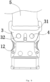
- the said clamping head housing includes a front housing and a rear housing, and the opposite walls of the front housing and the rear housing are respect ively set with a half recess forming the said cavity.
- a metal piece is further fixed between the upper ends of the front housing and the rear housing, and the upper end of the metal piece is set with a pull ring stretching out the top of the front housing and the rear housing.
- the belt and the clamping head housing can be connected when the belt passes through the pull ring and is tightened.
- the said automatic magnetic buckle, according to Claim 4 is characterized in that the said fastener unfolding device is a rope, and the two ends of the said rope are respectively fixed with the upper ends of the left fastener and the right fastener.
- the middle part of the rope passes through the clamping head housing from the top of the said cavity.
- the said fastener unfolding device has two pressing members, and the said pressing members include a pressing rod and a pressing head which are interconnected.
- the pressing rods of the two pressing members are respective ly in contact with the outer sides of the left fastener and the right fastener, and the said pressing head stretches out the outer periphery of the clamping head housing.
- the said clamping block is laterally set, and the end of the buckle block is set with a triangular or semi-circular notch.
- the said buckle head is a mushroom-shaped protrusion matching with the said clamping block.
- the mushroom-shaped protrusion is like a mushroom and comprises a lower cylinder and an upper clamping body.
- the diameter of the clamping body is greater than the diameter of the cylinder.
- the said two clamping blocks are clamped on the cylinder, and the two clamping blocks are located under the clamping body.
- the said buckle base has a plate shape, and the two ends of the buckle base are respectively set with long-striped webbing slots.
- the two long-striped slots are respectively set in parallel.
- another belt passes through the two long-striped webbing slots to firmly and stably connect the buckle base and the belt.
- the buckle base has a rectangular groove shape, the bottom of the buckle base is set with a rectangular groove-shaped webbing slot, and the long-striped webbing slot is set in parallel. During use, another belt passes through the two long-striped webbing slots to firmly and stably connect the buckle base and the belt.
- the upper surface of the buckle base is set with a circular groove, the inner diameter of the said circular groove is greater than the outer peripheral diameter of the clamping head housing, and the buckle head is located in the middle of the said circular groove.
- the circular groove can prevent the joint between the clamping head and the buckle base from being impacted by an external force and make the connection firm and stable.
- the said buckle base is cylindrical, the lower part of the buckle base is set with a metal piece, and the metal piece is set with a long-striped webbing slot.
- the upper surface of the buckle base is set with a circular groove, the inner diameter of the said circular groove is greater than the outer peripheral diameter of the clamping head housing, and the buckle head is located in the middle of the said circular groove.
- the opposite walls of the front housing and the rear housing are set with matching positioning columns and positioning holes, and the front housing and the rear housing are matched and connected with screws and nuts.
- the connection between the front housing and the rear housing is firm and stable without misplacement.
- a non-claimed method of using an automatic magnetic buckle includes the following steps:
- the present invention has the following advantageous effects:
- the structural design of the present invention is reasonable and ingenious.
- the fixed connection between the buckle base and the clamping head can be easily realized by the action of the magnetic subassembly, and the connection is stable and firm.
- the buckle base and the clamping head can be conveniently separated by the design of the fastener unfolding device.
- the buckle base and the clamping head can rotate at 360° , so the buckle base and the clamping head can be buckled or separated at any angle. It can be operated conveniently and saves time and effort.
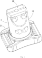
- An automatic magnetic buckle provided by the present embodiment comprises a matching clamping head 1 and a buckle base 2.
- the said clamping head 1 comprises a clamping head housing, and the said clamping head housing has a cavity extending through the upper and lower ends of the clamping head housing.
- the said cavity is set with a buckle subassembly
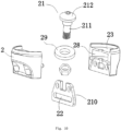
- the said buckle base 2 is set with a buckle head 21 matching with the said buckle subassembly
- the said clamping head 1 and the buckle base 2 are set with magnetic subassemblies which are mutually attracted.
- Clamping head 1 and buckle base 2 are attracted together through the matching of the magnetic subassembly.
- the buckle subassembly is matched with the buckle head 21 to securely connect the clamping head 1 and the buckle base 2.
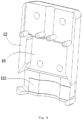
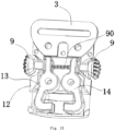
- the said buckle subassembly comprises a left fastener 13 and a right fastener 14 which are symmetrically set in the cavity and have the same structure.
- the middle parts of the said left fastener 13 and right fastener 14 are hinged asway in the cavity.
- a pressure spring 90 is connected between the upper inner sides of the left fastener 13 and the right fastener 14, and the upper opposite sides of the left fastener 13 and the right fastener 14 are respectively set with a spring positioning hole 132.
- the two ends of the said pressure spring are respectively set in the spring location hole 132.
- the lower ends of the left fastener 13 and the right fastener 14 are oppositely set with a clamping block 131 matching with the said buckle head 21.
- a fastener unfolding device is connected to the upper ends of the left fastener 13 and the right fastener 14.
- the middle part of the left fastener 13 and the right fastener 14 is set with a hinge hole 134.
- the left fastener 13 and the right fastener 14 can swing by matching the hinge hole 134 and the screw.
- An acting force is applied to the fastener unfolding device to make the upper parts of the left fastener 13 and the right fastener 14 swing toward each other.
- the distance between the lower parts of the left fastener 13 and the right fastener 14 is increased, and the buckle head 21 is not covered by the clamping block 131.
- An acting force is applied to the clamping head 1 and the buckle base 2. When the acting force is greater than the magnetic attraction force between the magnetic subassemblies, the buckle head 21 and the buckle base can be separated.
- the magnetic subassembly of the said clamping head 1 is set at a lower end of the said cavity, and the lower part of the said buckle subassembly is located at the magnetic subassembly of the clamping head 1.
- the magnetic subassembly of the said buckle base 2 is set in the said buckle base 2, and the magnetic subassembly of the said buckle base 2 is located under the said buckle head 21.
- the magnetic subassembly of the said buckle base 2 is a magnetic ring 29, and the magnetic ring 29 is fixed in the buckle base 2.
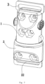
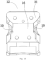
- the said clamping head housing includes a front housing 11 and a rear housing 12, and the opposite walls of the front housing 11 and the rear housing 12 are respectively set with a half recess 16 forming the said cavity.
- a metal piece 3 is further fixed between the upper ends of the front housing 11 and the rear housing 12.
- the upper opposite walls of the front housing 11 and the rear housing 12 are respectively set with a locating slot of the metal piece 31 (see Fig.15 ).
- the upper end of the metal piece 3 is set with a pull ring 31 stretching out the top of the front housing 11 and the rear housing 12.
- the lower end of the metal piece 3 is set with two pin holes 32, two pin shafts 4 are connected between the front housing 11 and the rear housing 12.
- the two pin holes 32 of the said metal piece 3 are covered with the said pin shafts 4 to fix the metal piece 3 with the front housing 11 and the rear housing 12.
- the belt 5 and the clamping head housing can be connected when the belt 5 passes through the pull ring 31 and is tightened.
- several tapered protrusions for fixing belts are set at the upper ends of the opposite walls of the front housing 11 and the rear housing 12. During assembly, one end of the belt is placed between the front housing 11 and the rear housing 12. When the front housing 11 and the rear housing 12 are fixedly connected, the tapered protrusion presses the said belt to fix the belt at the upper end of the clamping head housing.
- the magnetic subassembly of the clamping head 1 includes a front magnetic block and a rear magnetic block 121 (the front magnetic block and rear magnetic block 121 are not indicated in the figure).
- the front magnetic block and the rear magnetic block 121 are respectively fixed at the lower end of the recess 16 of the front housing 11 and the rear housing 12.
- the rear magnetic block 121 is fixed in the fixed slot at the lower end of the recess 16 of the rear housing 12, and the front magnetic block is fixed in the fixed slot at the lower end of the recess 16 of the front housing 11.
- the said fastener unfolding device is a rope 19, and the two ends of the said rope 19 are respectively fixed with the upper ends of the left fastener 13 and the right fastener 14.
- the upper ends of the left fastener 13 and the right fastener 14 are set with the rope fixing holes 133, and two ends of the said rope 19 are respectively fixed in the rope fixing holes 133 of the left fastener 13 and the right fastener 14.
- the middle part of the rope 19 passes through the clamping head housing from the top of the said cavity.
- the distance between the clamping blocks 131 is increased, and the buckle head 21 can be pulled out.
- the said clamping block is laterally set, and the end of the buckle block 13 1 is set with a triangular or semi-circular notch 1311.
- the said buckle head 21 is a mushroom-shaped protrusion matching with the said clamping block 131.
- the mushroom-shaped protrusion is like a mushroom and comprises a lower cylinder 211 and an upper clamping body 212.
- the diameter of the clamping body 212 is greater than the diameter of the cylinder 211.
- the buckle base 2 is set with nuts.
- the said cylinder 211 is connected with nuts.
- the said two clamping blocks 131 are clamped on the cylinder 211, and the two clamping blocks 131 are located under the clamping body 212.
- the said buckle base 2 has a plate shape, and the two ends of the buckle base are respectively set with long-striped webbing slots 22.
- the two long-striped slots 22 are respectively set in parallel.
- another belt passes through the two long-striped webbing slots 22 to firmly and stably connect between the buckle base 2 and the belt.
- the said buckle base 2 may also be in a rectangular groove shape, the bottom of the buckle base is set with a rectangular groove -shaped webbing slot 22, and the long-striped webbing slot 22 is set in parallel.
- another belt passes through the two long-striped webbing slots 22 to firmly and stably connect the buckle base and the belt.
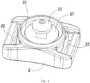
- the upper surface of the buckle base 2 is set with a circular groove 23, the inner diameter of the said circular groove 23 is greater than the outer peripheral diameter of the clamping head housing, and the said buckle head 21 is located in the middle of the said circular groove 23.
- the middle of the said circular groove 23 is further set with a receiving groove of magnetic ring 28.
- the said magnetic ring 29 is placed in the receiving groove of magnetic ring 28, and its position is limited by the cover plate 27 at the top of the receiving groove of magnetic ring 28.
- the circular groove 23 can prevent the joint between the clamping head 1 and the buckle base 2 from being impacted by an external force and make the connection firm and stable.
- the opposite walls of the front housing 11 and the rear housing 12 are set with matching positioning columns 17 and positioning holes, and the front housing 11 and the rear housing 12 are matched and connected with screws and nuts.
- the connection between the front housing 11 and the rear housing 12 is firm and stable without misplacement.
- a method of using an automatic magnetic buckle includes the following steps: Step 1: The buckle base 2 is close to the clamping head 1, and the buckle base 2 is mutually attracted with the magnetic subassembly on the clamping head 1. Under the action of the magnetic attraction force, the buckle head 21 is inserted into the cavity of the clamping head housing, the buckle subassembly is used to fix the buckle head 21, and the clamping head 1 is fixedly connected with the buckle base 2.
- Step 1 the magnetic force of the magnetic subassembly on the buckle base 2 and the clamping head 1 has the buckle base 2 and the clamping head 1 attached together. At this moment, the lower end of the clamping head is located in the said circular groove 23.
- the buckle head 21 is inserted between the two clamping blocks 131, and the clamping body 212 of the clamping head 21 is located above the clamping block 131. Due to the action of the pressure spring, the cylinder 211 of the two clamping blocks 131.
- the matching of the buckle head 21 and the clamping block 131 makes the connection between the buckle base 2 and the clamping head 1 stable and firm.
- Step 2 An acting force is applied to the left fastener 13 and the right fastener 14 via the fastener unfolding device to make the upper ends of the left fastener 13 and the right fastener 14 swing toward each other.
- the distance between the two clamping blocks 131 is increased, and the buckle head 21 can be removed from the clamping head 1 to separate the clamping head 1 and the buckle base 2.
- Step 2 the rope 19 is pulled up to make the upper ends of the left fastener 13 and the right fastener 14 swing toward each other.
- the distance between the two clamping blocks 131 is increased.
- the buckle head 21 can be pull out from the clamping head 1.
- a rope passes through the two long strip-shaped grooves 22 and fixedly connects with people, animals or other objects which need to be towed.
- the upper end of the clamping head housing is fixedly connected with the tow rope to conveniently fix and connect the tow rope to people, animals or other objects which need to be towed. They can be separated very easily.
- the structural design of the present invention is reasonable and ingenious.
- the fixed connection between the buckle base 2 and the clamping head 1 can be easily realized by the action of the magnetic subassembly, and the connection is stable and firm.
- the buckle base 2 and the clamping head 1 can be conveniently separated by the design of the fastener unfolding device.
- the buckle base and the clamping head can rotate at 360° , so the buckle base and the clamping head can be buckled or separated at any angle. It can be operated conveniently and saves time and effort.
- the present embodiment is substantially the same as Embodiment 1, but their differences are as follows:
- the said buckle base 2 is cylindrical, the lower part of the buckle base 2 is set with a metal piece 210, and the metal piece 210 is set with a long-striped webbing slot 22.
- the upper surface of the buckle base 2 is set with a circular groove 23, the inner diameter of the said circular groove 23 is greater than the outer peripheral diameter of the clamping head housing, and the said buckle head 21 is located in the middle of the said circular groove 23.
- the middle of the said buckle base 2 is further set with a receiving groove of magnetic ring 28.
- the said buckle head 21 is a mushroom-shaped protrusion matching with the said clamping block 131.
- the mushroom-shaped protrusion is like a mushroom and comprises a lower cylinder 211 and an upper clamping body 212.
- the diameter of the clamping body 212 is greater than the diameter of the cylinder 211.
- the buckle base 2 is set with nuts.
- the said cylinder 211 is connected with nuts.
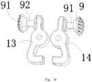
- the present embodiment is substantially the same as Embodiments 1 and 2, but their differences are as follows: the said fastener unfolding device has two pressing members 9, and the said pressing members include a pressing rod 91 and a pressing head 92 which are interconnected.
- the pressing rods 91 of the two pressing members 9 are respectively in contact with the outer sides of the left fastener 13 and the right fastener 14, and the said pressing head 92 stretches out the outer periphery of the clamping head housing.
- the said clamping head housing includes a front housing 11 and a rear housing 12, and the opposite walls of the front housing 11 and the rear housing 12 are respectively set with a half recess 16 forming the said cavity.
- the opposite walls of the front housing 11 and the rear housing 12 are respectively relative to the pressing rod 91 and the pressing head 92, forming a holding tank 10.
Landscapes
- Buckles (AREA)
Claims (8)
- - Automatischer Magnetverschluss, der einen passenden Klemmkopf (1) und eine Verschlussbasis (2) umfasst, wobei der Klemmkopf (1) ein Klemmkopfgehäuse umfasst und das Klemmkopfgehäuse einen Hohlraum aufweist, der sich durch das obere und das untere Ende des Klemmkopfgehäuses erstreckt, wobei der Hohlraum mit einer Verschlussunterbaugruppe versehen ist und die Verschlussbasis mit einem Verschlusskopf (21) versehen ist, der mit der Verschlussunterbaugruppe zusammenpasst, und der Klemmkopf (1) und die Verschlussbasis (2) mit magnetischen Unterbaugruppen versehen sind, die sich gegenseitig anziehen,wobei die magnetische Unterbaugruppe des Klemmkopfes (1) an einem unteren Ende des Hohlraums bereitgestellt ist und der untere Teil der Verschlussunterbaugruppe an der magnetischen Unterbaugruppe des Klemmkopfes (1) angeordnet ist,wobei die magnetische Unterbaugruppe der Verschlussbasis (2) in der Verschlussbasis (2) bereitgestellt ist und die magnetische Unterbaugruppe der Verschlussbasis (2) unter dem Verschlusskopf (21) angeordnet ist,wobei die Verschlussbasis (2) eine Plattenform aufweist und die zwei Enden der Verschlussbasis (2) jeweils mit langgestreckten Gurtbandschlitzen (22) versehen sind, die entsprechend parallel bereitgestellt sind, oder wobei die Verschlussbasis (2) zylinderförmig ist, wobei der untere Teil der Verschlussbasis (2) mit einem Metallstück (210) versehen ist und das Metallstück (210) mit einem langgestreckten Gurtbandschlitz (22) versehen ist,wobei die Oberseite der Verschlussbasis (2) mit einer kreisförmigen Auskehlung (23) versehen ist, wobei der Innendurchmesser der kreisförmigen Auskehlung (23) größer als der Außenumfangsdurchmesser des Klemmkopfgehäuses ist und der Verschlusskopf (21) in der Mitte der kreisförmigen Auskehlung (23) angeordnet ist, unddadurch gekennzeichnet, dass die Mitte der kreisförmigen Auskehlung (23) ferner mit einer aufnehmenden Auskehlung (28) für einen Magnetring versehen ist, wobei der Magnetring (29) in der aufnehmenden Auskehlung (28) für den Magnetring platziert ist und seine Position durch eine Deckplatte (27) an der Oberseite der aufnehmenden Auskehlung (28) für den Magnetring begrenzt ist.
- - Automatischer Magnetverschluss nach Anspruch 1, dadurch gekennzeichnet, dass die Verschlussunterbaugruppe ein linkes Befestigungsmittel (13) und ein rechtes Befestigungsmittel (14) umfasst, die in dem Hohlraum symmetrisch bereitgestellt sind und die gleiche Struktur aufweisen, wobei die Mittelteile des linken Befestigungsmittels (13) und des rechten Befestigungsmittels (14) schwenkbar in dem Hohlraum angelenkt sind, wobei zwischen den oberen Innenseiten des linken Befestigungsmittels (13) und des rechten Befestigungsmittels (14) eine Druckfeder (90) eingebunden ist und die unteren Enden des linken Befestigungsmittels (13) und des rechten Befestigungsmittels (14) gegenüberliegend mit einem Klemmblock (131) versehen sind, der mit dem Verschlusskopf (21) zusammenpasst, wobei eine Befestigungsmittel-Ausklappvorrichtung mit den oberen Enden des linken Befestigungsmittels (13) und des rechten Befestigungsmittels (14) verbunden ist.
- - Automatischer Magnetverschluss nach Anspruch 1 oder 2, dadurch gekennzeichnet, dass das Klemmkopfgehäuse ein vorderes Gehäuse (11) und ein hinteres Gehäuse (12) beinhaltet und die gegenüberliegenden Wände des vorderen Gehäuses (11) und des hinteren Gehäuses (12) jeweils mit einer halben Vertiefung (16) gebildet sind, die den Hohlraum bildet,
wobei zwischen den oberen Enden des vorderen Gehäuses (11) und des hinteren Gehäuses (12) ferner ein Metallstück (3) fixiert ist und das obere Ende des Metallstücks (3) mit einem Zugring (31) versehen ist, der sich aus der Oberseite des vorderen Gehäuses (11) und des hinteren Gehäuses (12) ausdehnt. - - Automatischer Magnetverschluss nach Anspruch 2, dadurch gekennzeichnet, dass die Befestigungsmittel-Ausklappvorrichtung ein Seil (19) ist und die zwei Enden des Seils (19) an den oberen Enden des linken Befestigungsmittels (13) beziehungsweise des rechten Befestigungsmittels (14) fixiert sind, wobei der Mittelteil des Seils (19) von der Oberseite des Hohlraums durch das Klemmkopfgehäuse verläuft.
- - Automatischer Magnetverschluss nach Anspruch 2, dadurch gekennzeichnet, dass die Befestigungsmittel-Ausklappvorrichtung zwei Presselemente aufweist und die Presselemente einen Pressstab (91) und einen Presskopf (92) beinhalten, die miteinander verbunden sind, wobei die Pressstäbe (91) der zwei Presselemente jeweils in Kontakt mit den Außenseiten des linken Befestigungsmittels (13) und des rechten Befestigungsmittels (14) stehen und sich der Presskopf (92) aus dem Außenumfang des Klemmkopfgehäuses erstreckt.
- - Automatischer Magnetverschluss nach Anspruch 2, dadurch gekennzeichnet, dass der Klemmblock seitlich bereitgestellt ist und das Ende des Verschlussblocks (131) mit einer dreieckigen oder halbrunden Kerbe (1311) versehen ist, wobei der Verschlusskopf (21) ein pilzförmiger Vorsprung ist, der mit dem Klemmblock (131) zusammenpasst.
- - Automatischer Magnetverschluss nach Anspruch 3, dadurch gekennzeichnet, dass die gegenüberliegenden Wände des vorderen Gehäuses (11) und des hinteren Gehäuses (12) mit zusammenpassenden Positionierungsstützen (17) und Positionierungsöffnungen versehen sind und das vordere Gehäuse (11) und das hintere Gehäuse (12) zusammenpassend und mit Schrauben und Muttern verbunden sind.
- - Automatischer Magnetverschluss nach Anspruch 1, dadurch gekennzeichnet, dass die Verschlussbasis (2) die Form einer rechteckigen Auskehlung aufweist, wobei der Boden der Verschlussbasis (2) mit einem rechteckigen auskehlungsförmigen Gurtbandschlitz (22) versehen ist und der langgestreckte Gurtbandschlitz parallel bereitgestellt ist.
Priority Applications (3)
| Application Number | Priority Date | Filing Date | Title |
|---|---|---|---|
| PL18191645.3T PL3616552T3 (pl) | 2018-08-30 | 2018-08-30 | Automatyczna klamra magnetyczna i sposób jej zastosowania |
| ES18191645T ES2956111T3 (es) | 2018-08-30 | 2018-08-30 | Una hebilla magnética automática y su método de uso |
| EP18191645.3A EP3616552B1 (de) | 2018-08-30 | 2018-08-30 | Automatische magnetische schnalle und deren verwendungsverfahren |
Applications Claiming Priority (1)
| Application Number | Priority Date | Filing Date | Title |
|---|---|---|---|
| EP18191645.3A EP3616552B1 (de) | 2018-08-30 | 2018-08-30 | Automatische magnetische schnalle und deren verwendungsverfahren |
Publications (3)
| Publication Number | Publication Date |
|---|---|
| EP3616552A1 EP3616552A1 (de) | 2020-03-04 |
| EP3616552B1 true EP3616552B1 (de) | 2023-07-05 |
| EP3616552C0 EP3616552C0 (de) | 2023-07-05 |
Family
ID=63449337
Family Applications (1)
| Application Number | Title | Priority Date | Filing Date |
|---|---|---|---|
| EP18191645.3A Active EP3616552B1 (de) | 2018-08-30 | 2018-08-30 | Automatische magnetische schnalle und deren verwendungsverfahren |
Country Status (3)
| Country | Link |
|---|---|
| EP (1) | EP3616552B1 (de) |
| ES (1) | ES2956111T3 (de) |
| PL (1) | PL3616552T3 (de) |
Families Citing this family (6)
| Publication number | Priority date | Publication date | Assignee | Title |
|---|---|---|---|---|
| US10874178B2 (en) | 2017-12-07 | 2020-12-29 | Wonderland Switzerland Ag | Magnetic buckling assembly |
| CN209573440U (zh) | 2018-09-20 | 2019-11-05 | 明门(中国)幼童用品有限公司 | 预防意外释锁的扣具 |
| KR102450616B1 (ko) | 2019-06-06 | 2022-10-05 | 원더랜드 스위처랜드 아게 | 자기 버클 어셈블리 |
| CN117016926A (zh) | 2019-07-17 | 2023-11-10 | 明门瑞士股份有限公司 | 扣具 |
| CN112237315B (zh) | 2019-07-17 | 2023-09-29 | 明门瑞士股份有限公司 | 扣具 |
| DE102021200260B3 (de) * | 2021-01-13 | 2022-03-24 | Fidlock Gmbh | Magnet-mechanische Verschlussvorrichtung |
Family Cites Families (5)
| Publication number | Priority date | Publication date | Assignee | Title |
|---|---|---|---|---|
| US20130185901A1 (en) * | 2012-01-19 | 2013-07-25 | Pet Connect, Incorporated | Magnet-assisted quick-connect quick-disconnect mechanism |
| GB2511104B (en) * | 2013-02-25 | 2015-06-24 | Magloc Ip Ltd | Connector |
| CN104421253B (zh) * | 2013-09-11 | 2016-06-08 | 王桂生 | 磁性锁扣 |
| CN107448445B (zh) * | 2017-09-12 | 2023-02-21 | 东莞明冠织带制品有限公司 | 一种自动磁力卡扣及自动扣合方法 |
| DE202018101841U1 (de) * | 2018-04-05 | 2018-04-27 | Jérôme Glozbach de Cabarrus | Verschlussvorrichtung zum lösbaren Verbinden eines ersten Teils mit einem zweiten Teil |
-
2018
- 2018-08-30 EP EP18191645.3A patent/EP3616552B1/de active Active
- 2018-08-30 PL PL18191645.3T patent/PL3616552T3/pl unknown
- 2018-08-30 ES ES18191645T patent/ES2956111T3/es active Active
Also Published As
| Publication number | Publication date |
|---|---|
| PL3616552T3 (pl) | 2023-12-11 |
| EP3616552A1 (de) | 2020-03-04 |
| ES2956111T3 (es) | 2023-12-13 |
| EP3616552C0 (de) | 2023-07-05 |
Similar Documents
| Publication | Publication Date | Title |
|---|---|---|
| EP3616552B1 (de) | Automatische magnetische schnalle und deren verwendungsverfahren | |
| US10791804B2 (en) | Automatic magnetic buckle and its use method | |
| US4697783A (en) | Quick release night vision goggle mounting bracket | |
| US4670912A (en) | Adjustable night vision goggle mounting bracket | |
| AU643801B2 (en) | A device for providing detachable assembly | |
| US10912361B2 (en) | Strap attachment | |
| EP0021849A1 (de) | Wiederverwendbare, auslösefähige Befestigung | |
| ATE397743T1 (de) | Montageeinrichtung | |
| TWI674853B (zh) | 自動磁力卡扣及其使用方法 | |
| US4450992A (en) | Belt buckle-mini-revolver combination | |
| US4809942A (en) | Quick release night vision goggle mounting bracket | |
| HK47997A (en) | Snap fastener with separator spring | |
| EP1680971A3 (de) | Zunge für einen aufblasbaren Sicherheitsgürtel | |
| US10876557B2 (en) | Container connection system | |
| CN107581727B (zh) | 一种双按钮弹簧扣装配系统 | |
| US20260008403A1 (en) | Detachable Tie Down | |
| JP2020031890A (ja) | 自動磁気留め金及びその使用方法 | |
| CN209403729U (zh) | 一种自动磁力卡扣 | |
| TWM590516U (zh) | 機械手臂與手術器械之快速組拆裝置 | |
| CN108720520B (zh) | 一种磁吸式快速挂钩 | |
| CN210016082U (zh) | 一种用于快装连接器的压接工具 | |
| CN221325247U (zh) | 一种快拆式磁吸扣 | |
| CN217682601U (zh) | 一种可锁止磁吸扣 | |
| RU225013U1 (ru) | Силовой замок крепления полезной нагрузки беспилотного летательного аппарата | |
| CN215717948U (zh) | 押解安全带 |
Legal Events
| Date | Code | Title | Description |
|---|---|---|---|
| PUAI | Public reference made under article 153(3) epc to a published international application that has entered the european phase |
Free format text: ORIGINAL CODE: 0009012 |
|
| STAA | Information on the status of an ep patent application or granted ep patent |
Free format text: STATUS: REQUEST FOR EXAMINATION WAS MADE |
|
| 17P | Request for examination filed |
Effective date: 20180927 |
|
| AK | Designated contracting states |
Kind code of ref document: A1 Designated state(s): AL AT BE BG CH CY CZ DE DK EE ES FI FR GB GR HR HU IE IS IT LI LT LU LV MC MK MT NL NO PL PT RO RS SE SI SK SM TR |
|
| AX | Request for extension of the european patent |
Extension state: BA ME |
|
| STAA | Information on the status of an ep patent application or granted ep patent |
Free format text: STATUS: EXAMINATION IS IN PROGRESS |
|
| 17Q | First examination report despatched |
Effective date: 20220228 |
|
| GRAP | Despatch of communication of intention to grant a patent |
Free format text: ORIGINAL CODE: EPIDOSNIGR1 |
|
| STAA | Information on the status of an ep patent application or granted ep patent |
Free format text: STATUS: GRANT OF PATENT IS INTENDED |
|
| INTG | Intention to grant announced |
Effective date: 20230130 |
|
| GRAS | Grant fee paid |
Free format text: ORIGINAL CODE: EPIDOSNIGR3 |
|
| GRAA | (expected) grant |
Free format text: ORIGINAL CODE: 0009210 |
|
| STAA | Information on the status of an ep patent application or granted ep patent |
Free format text: STATUS: THE PATENT HAS BEEN GRANTED |
|
| AK | Designated contracting states |
Kind code of ref document: B1 Designated state(s): AL AT BE BG CH CY CZ DE DK EE ES FI FR GB GR HR HU IE IS IT LI LT LU LV MC MK MT NL NO PL PT RO RS SE SI SK SM TR |
|
| REG | Reference to a national code |
Ref country code: CH Ref legal event code: EP |
|
| REG | Reference to a national code |
Ref country code: AT Ref legal event code: REF Ref document number: 1583986 Country of ref document: AT Kind code of ref document: T Effective date: 20230715 |
|
| REG | Reference to a national code |
Ref country code: DE Ref legal event code: R096 Ref document number: 602018052728 Country of ref document: DE |
|
| REG | Reference to a national code |
Ref country code: IE Ref legal event code: FG4D |
|
| U01 | Request for unitary effect filed |
Effective date: 20230803 |
|
| U07 | Unitary effect registered |
Designated state(s): AT BE BG DE DK EE FI FR IT LT LU LV MT NL PT SE SI Effective date: 20230808 |
|
| REG | Reference to a national code |
Ref country code: LT Ref legal event code: MG9D |
|
| U20 | Renewal fee for the european patent with unitary effect paid |
Year of fee payment: 6 Effective date: 20230920 |
|
| REG | Reference to a national code |
Ref country code: ES Ref legal event code: FG2A Ref document number: 2956111 Country of ref document: ES Kind code of ref document: T3 Effective date: 20231213 |
|
| PG25 | Lapsed in a contracting state [announced via postgrant information from national office to epo] |
Ref country code: GR Free format text: LAPSE BECAUSE OF FAILURE TO SUBMIT A TRANSLATION OF THE DESCRIPTION OR TO PAY THE FEE WITHIN THE PRESCRIBED TIME-LIMIT Effective date: 20231006 |
|
| PG25 | Lapsed in a contracting state [announced via postgrant information from national office to epo] |
Ref country code: IS Free format text: LAPSE BECAUSE OF FAILURE TO SUBMIT A TRANSLATION OF THE DESCRIPTION OR TO PAY THE FEE WITHIN THE PRESCRIBED TIME-LIMIT Effective date: 20231105 |
|
| PG25 | Lapsed in a contracting state [announced via postgrant information from national office to epo] |
Ref country code: RS Free format text: LAPSE BECAUSE OF FAILURE TO SUBMIT A TRANSLATION OF THE DESCRIPTION OR TO PAY THE FEE WITHIN THE PRESCRIBED TIME-LIMIT Effective date: 20230705 Ref country code: NO Free format text: LAPSE BECAUSE OF FAILURE TO SUBMIT A TRANSLATION OF THE DESCRIPTION OR TO PAY THE FEE WITHIN THE PRESCRIBED TIME-LIMIT Effective date: 20231005 Ref country code: IS Free format text: LAPSE BECAUSE OF FAILURE TO SUBMIT A TRANSLATION OF THE DESCRIPTION OR TO PAY THE FEE WITHIN THE PRESCRIBED TIME-LIMIT Effective date: 20231105 Ref country code: HR Free format text: LAPSE BECAUSE OF FAILURE TO SUBMIT A TRANSLATION OF THE DESCRIPTION OR TO PAY THE FEE WITHIN THE PRESCRIBED TIME-LIMIT Effective date: 20230705 Ref country code: GR Free format text: LAPSE BECAUSE OF FAILURE TO SUBMIT A TRANSLATION OF THE DESCRIPTION OR TO PAY THE FEE WITHIN THE PRESCRIBED TIME-LIMIT Effective date: 20231006 |
|
| REG | Reference to a national code |
Ref country code: DE Ref legal event code: R097 Ref document number: 602018052728 Country of ref document: DE |
|
| PG25 | Lapsed in a contracting state [announced via postgrant information from national office to epo] |
Ref country code: SM Free format text: LAPSE BECAUSE OF FAILURE TO SUBMIT A TRANSLATION OF THE DESCRIPTION OR TO PAY THE FEE WITHIN THE PRESCRIBED TIME-LIMIT Effective date: 20230705 Ref country code: RO Free format text: LAPSE BECAUSE OF FAILURE TO SUBMIT A TRANSLATION OF THE DESCRIPTION OR TO PAY THE FEE WITHIN THE PRESCRIBED TIME-LIMIT Effective date: 20230705 Ref country code: CZ Free format text: LAPSE BECAUSE OF FAILURE TO SUBMIT A TRANSLATION OF THE DESCRIPTION OR TO PAY THE FEE WITHIN THE PRESCRIBED TIME-LIMIT Effective date: 20230705 Ref country code: MC Free format text: LAPSE BECAUSE OF FAILURE TO SUBMIT A TRANSLATION OF THE DESCRIPTION OR TO PAY THE FEE WITHIN THE PRESCRIBED TIME-LIMIT Effective date: 20230705 Ref country code: SK Free format text: LAPSE BECAUSE OF FAILURE TO SUBMIT A TRANSLATION OF THE DESCRIPTION OR TO PAY THE FEE WITHIN THE PRESCRIBED TIME-LIMIT Effective date: 20230705 |
|
| PLBE | No opposition filed within time limit |
Free format text: ORIGINAL CODE: 0009261 |
|
| STAA | Information on the status of an ep patent application or granted ep patent |
Free format text: STATUS: NO OPPOSITION FILED WITHIN TIME LIMIT |
|
| REG | Reference to a national code |
Ref country code: IE Ref legal event code: MM4A |
|
| 26N | No opposition filed |
Effective date: 20240408 |
|
| PG25 | Lapsed in a contracting state [announced via postgrant information from national office to epo] |
Ref country code: IE Free format text: LAPSE BECAUSE OF NON-PAYMENT OF DUE FEES Effective date: 20230830 |
|
| PG25 | Lapsed in a contracting state [announced via postgrant information from national office to epo] |
Ref country code: IE Free format text: LAPSE BECAUSE OF NON-PAYMENT OF DUE FEES Effective date: 20230830 |
|
| U20 | Renewal fee for the european patent with unitary effect paid |
Year of fee payment: 7 Effective date: 20240826 |
|
| PG25 | Lapsed in a contracting state [announced via postgrant information from national office to epo] |
Ref country code: CY Free format text: LAPSE BECAUSE OF FAILURE TO SUBMIT A TRANSLATION OF THE DESCRIPTION OR TO PAY THE FEE WITHIN THE PRESCRIBED TIME-LIMIT; INVALID AB INITIO Effective date: 20180830 |
|
| PG25 | Lapsed in a contracting state [announced via postgrant information from national office to epo] |
Ref country code: HU Free format text: LAPSE BECAUSE OF FAILURE TO SUBMIT A TRANSLATION OF THE DESCRIPTION OR TO PAY THE FEE WITHIN THE PRESCRIBED TIME-LIMIT; INVALID AB INITIO Effective date: 20180830 |
|
| U20 | Renewal fee for the european patent with unitary effect paid |
Year of fee payment: 8 Effective date: 20250821 |
|
| PGFP | Annual fee paid to national office [announced via postgrant information from national office to epo] |
Ref country code: ES Payment date: 20250903 Year of fee payment: 8 |
|
| PGFP | Annual fee paid to national office [announced via postgrant information from national office to epo] |
Ref country code: TR Payment date: 20250825 Year of fee payment: 8 Ref country code: PL Payment date: 20250825 Year of fee payment: 8 |
|
| PGFP | Annual fee paid to national office [announced via postgrant information from national office to epo] |
Ref country code: GB Payment date: 20250821 Year of fee payment: 8 |
|
| PGFP | Annual fee paid to national office [announced via postgrant information from national office to epo] |
Ref country code: CH Payment date: 20250908 Year of fee payment: 8 |