EP3615984B1 - Head-up-display - Google Patents
Head-up-display Download PDFInfo
- Publication number
- EP3615984B1 EP3615984B1 EP18722927.3A EP18722927A EP3615984B1 EP 3615984 B1 EP3615984 B1 EP 3615984B1 EP 18722927 A EP18722927 A EP 18722927A EP 3615984 B1 EP3615984 B1 EP 3615984B1
- Authority
- EP
- European Patent Office
- Prior art keywords
- head
- display
- light
- light tunnel
- display according
- Prior art date
- Legal status (The legal status is an assumption and is not a legal conclusion. Google has not performed a legal analysis and makes no representation as to the accuracy of the status listed.)
- Active
Links
Images

Classifications
-
- B—PERFORMING OPERATIONS; TRANSPORTING
- B60—VEHICLES IN GENERAL
- B60K—ARRANGEMENT OR MOUNTING OF PROPULSION UNITS OR OF TRANSMISSIONS IN VEHICLES; ARRANGEMENT OR MOUNTING OF PLURAL DIVERSE PRIME-MOVERS IN VEHICLES; AUXILIARY DRIVES FOR VEHICLES; INSTRUMENTATION OR DASHBOARDS FOR VEHICLES; ARRANGEMENTS IN CONNECTION WITH COOLING, AIR INTAKE, GAS EXHAUST OR FUEL SUPPLY OF PROPULSION UNITS IN VEHICLES
- B60K35/00—Instruments specially adapted for vehicles; Arrangement of instruments in or on vehicles
- B60K35/20—Output arrangements, i.e. from vehicle to user, associated with vehicle functions or specially adapted therefor
- B60K35/21—Output arrangements, i.e. from vehicle to user, associated with vehicle functions or specially adapted therefor using visual output, e.g. blinking lights or matrix displays
- B60K35/23—Head-up displays [HUD]
-
- B—PERFORMING OPERATIONS; TRANSPORTING
- B60—VEHICLES IN GENERAL
- B60K—ARRANGEMENT OR MOUNTING OF PROPULSION UNITS OR OF TRANSMISSIONS IN VEHICLES; ARRANGEMENT OR MOUNTING OF PLURAL DIVERSE PRIME-MOVERS IN VEHICLES; AUXILIARY DRIVES FOR VEHICLES; INSTRUMENTATION OR DASHBOARDS FOR VEHICLES; ARRANGEMENTS IN CONNECTION WITH COOLING, AIR INTAKE, GAS EXHAUST OR FUEL SUPPLY OF PROPULSION UNITS IN VEHICLES
- B60K35/00—Instruments specially adapted for vehicles; Arrangement of instruments in or on vehicles
- B60K35/80—Arrangements for controlling instruments
-
- G—PHYSICS
- G02—OPTICS
- G02B—OPTICAL ELEMENTS, SYSTEMS OR APPARATUS
- G02B27/00—Optical systems or apparatus not provided for by any of the groups G02B1/00 - G02B26/00, G02B30/00
- G02B27/01—Head-up displays
- G02B27/0101—Head-up displays characterised by optical features
-
- G—PHYSICS
- G02—OPTICS
- G02B—OPTICAL ELEMENTS, SYSTEMS OR APPARATUS
- G02B27/00—Optical systems or apparatus not provided for by any of the groups G02B1/00 - G02B26/00, G02B30/00
- G02B27/01—Head-up displays
- G02B27/0149—Head-up displays characterised by mechanical features
-
- G—PHYSICS
- G02—OPTICS
- G02B—OPTICAL ELEMENTS, SYSTEMS OR APPARATUS
- G02B5/00—Optical elements other than lenses
- G02B5/30—Polarising elements
-
- B—PERFORMING OPERATIONS; TRANSPORTING
- B60—VEHICLES IN GENERAL
- B60K—ARRANGEMENT OR MOUNTING OF PROPULSION UNITS OR OF TRANSMISSIONS IN VEHICLES; ARRANGEMENT OR MOUNTING OF PLURAL DIVERSE PRIME-MOVERS IN VEHICLES; AUXILIARY DRIVES FOR VEHICLES; INSTRUMENTATION OR DASHBOARDS FOR VEHICLES; ARRANGEMENTS IN CONNECTION WITH COOLING, AIR INTAKE, GAS EXHAUST OR FUEL SUPPLY OF PROPULSION UNITS IN VEHICLES
- B60K35/00—Instruments specially adapted for vehicles; Arrangement of instruments in or on vehicles
- B60K35/60—Instruments characterised by their location or relative disposition in or on vehicles
-
- G—PHYSICS
- G02—OPTICS
- G02B—OPTICAL ELEMENTS, SYSTEMS OR APPARATUS
- G02B27/00—Optical systems or apparatus not provided for by any of the groups G02B1/00 - G02B26/00, G02B30/00
- G02B27/01—Head-up displays
- G02B27/0101—Head-up displays characterised by optical features
- G02B2027/0118—Head-up displays characterised by optical features comprising devices for improving the contrast of the display / brillance control visibility
-
- G—PHYSICS
- G02—OPTICS
- G02B—OPTICAL ELEMENTS, SYSTEMS OR APPARATUS
- G02B27/00—Optical systems or apparatus not provided for by any of the groups G02B1/00 - G02B26/00, G02B30/00
- G02B27/01—Head-up displays
- G02B27/0149—Head-up displays characterised by mechanical features
- G02B2027/0154—Head-up displays characterised by mechanical features with movable elements
- G02B2027/0156—Head-up displays characterised by mechanical features with movable elements with optionally usable elements
Definitions
- the present invention relates to a head-up display in which a display unit is protected from damage by light incident from outside, and a method for its operation.
- a head-up display creates a virtual image visible to the driver on the windshield. This image is usually generated on a display unit, for example a liquid crystal display (LCD, Liquid Crystal Display) and reflected through a hole in the dashboard onto the windshield by means of mirrors.
- Head-up displays are often protected from solar radiation by complex and expensive measures such as polarization films, cold-light mirrors and the like, in order to protect the display unit from overheating in particular.
- the disadvantage of this is that the costs of the countermeasures, in particular the costs for polarizing films or cold-light mirrors, are quite high. In addition, these measures only delay the damage to the display unit for a certain time, but do not completely prevent it.
- a disadvantage of using countermeasures based on polarization is that unpleasant side effects occur, such as a disappearing image when the driver uses polarizing sunglasses. Polarizing films placed on the head-up display shimmer and are therefore often seen as irritating.
- the EP 2 843 652 A1 shows a head-up display with a display element, the image of which is thrown at a critical angle onto a mirror unit of a vehicle by means of an optical path, and from there is reflected in the direction of the driver, superimposed on an image of the surroundings.
- Its display element is protected against damage from direct sunlight by using a light-sensitive sensor to detect the sunlight detected, and if the intensity is too high, the luminosity of a lighting unit for the display element is reduced or the lighting unit is switched off completely. This reduces the total amount of light incident on the display element, increasing its lifespan.
- the intensity of the incident sunlight is not limited, which means that damage to the display element is only postponed but not prevented.
- a head-up display in which the rise in temperature of a display element is limited.
- an assessment is made as to whether the current position of the sun is such that there is a risk that too much sunlight will fall on the display element, the temperature of which will increase too much and the display element will be damaged as a result.
- the light falling on the display element is reduced by inserting a filter in the optical path.
- the disadvantage of this is that the estimate can be wrong, especially if it is based on an incorrectly determined geographic position of the vehicle, the wrong time of day, or if the weather means that there is hardly any direct sunlight on the display element anyway.
- the optical filter also reduces the amount of light in the image of the head-up display directed in the direction of the driver, so that the latter has to do without an optimally bright image of the display for no reason.
- a head-up display has a control unit, at the input of which the signal from the sensor is present and whose control output is connected to a parking facility for the head-up display. If there is a strong incidence of light at the critical angle, this is detected by the sensor, whereupon the parking unit, controlled by the control unit, moves the head-up display into a parking position in which the light falling at the critical angle does not fall on the display element.
- a liquid crystal element also known as an LC display or LCD, is provided as a display element, an OLED element that has organic light-emitting diodes, or another display element that reacts sensitively to certain frequencies of the incident light or is generally protected from overheating by incident light protect is.
- the windshield is generally used as the mirror unit, or what is known as a combiner, a partially transparent mirror which is arranged between the driver and the windshield.
- the vehicle can be provided both as a land vehicle, as a water vehicle and as an aircraft.
- the driver in the direction of which the image of the display element superimposed on the surrounding image is directed, is preferably the driver of the vehicle. However, the superimposed image can also be provided here additionally or alternatively for the passenger or another passenger in the vehicle.
- the sensor is an angle-dependent sensor that detects ambient light that enters the optical path at the critical angle coming from the mirror unit.
- ambient light that falls at this angle and in an angular range around it, reaches the display element completely or to a large extent and, if it is exposed to it for a longer period of time or if it is of very high intensity for a short time, it damages it.
- the head-up display is therefore included in this critical angular range incident ambient light in a parking position. Damaging ambient light is generally direct sunlight, but can also come from other strong light sources that overheat or otherwise damage the display element.
- a head-up display according to the invention as claimed in claim 1 has a light tunnel which is aligned according to the critical angle and at the end of which the sensor is arranged. This ensures that the sensor only registers light that is incident at the critical angle or in the critical angle range. Therefore, the sensor itself does not need to have a special angle-dependent configuration, it is therefore simple in construction and inexpensive.
- the light tunnel is inexpensively integrated into the housing of the head-up display or into another component of the head-up display, for example into a plastic component produced using an injection molding process.
- the light tunnel has one or more absorbing wall surfaces on its inside. This causes only light incident at the critical angle to pass straight through the tunnel, while light incident outside the critical angle range from the wall surfaces and is therefore not detected by the sensor.
- One or more conically inclined wall surfaces enable the critical angle to be extended to a critical angle range, for example to a +/-5° deviation from the critical angle in which ambient light that is also incident at too high an intensity leads to damage to the display element.
- the light tunnel is designed, for example, as a round cone, that is to say with a single conically inclined wall surface.
- a plurality of conically inclined wall surfaces form the surface of a cone having a non-circular cross-section, such as a square or hexagonal cross-section, or an irregularly shaped cross-section. Shapes of this type, deviating from a round cone, are suitable for adapting the critical angle range detected by the sensor to the geometric shape of the display element.
- One or more separating surfaces arranged between the wall surfaces of the light tunnel which are aligned essentially parallel to the wall surfaces, also mean that only light from the critical angle or critical angle range falls on the sensor element, even if the cross section of the light tunnel is selected to be relatively large or its length is relatively short compared to the cross-section.
- many small light tunnels are formed by the wall surfaces, which also ensure a high angular selectivity despite an unfavorable ratio between length and cross-section of the light tunnel.
- several separating surfaces are used, but in the case of a large length and a comparatively small cross section of the light tunnel, one separating surface can also be sufficient to achieve the desired angular selectivity.
- the separating surfaces are preferably aligned with the same vanishing point as the walls of the funnel.
- the light tunnel is arranged on a housing of the head-up display in the vicinity of the light exit opening of the beam path.
- This has the advantage that the critical angle can still be determined easily here and there is still no influence from elements arranged inside the head-up display, which would make it difficult to align the light tunnel at the correct angle.
- the light tunnel is preferably formed in one piece with the housing, for example as a plastic part which is produced simultaneously with the housing in an injection molding process, or as a separate component which is injected into the housing during its manufacture or is inserted into a housing opening.
- the control unit has a delay unit and, alternatively or additionally, an integration unit.
- the delay unit means that if the intensity of the incident light at the critical angle exceeds a threshold value for just a short time, this does not result in the parking position being assumed.
- an integration unit is provided that the intensity of the incident light over a certain Period integrated, and means that the parking position is only taken if a certain total energy has fallen within a certain critical period. It releases the parking position again when the total energy has fallen below a critical value again. This makes sense, for example, when driving through a tree-lined avenue where, due to the gaps between the leaves, a high light intensity only falls on the sensor for a short time, but over a longer period of time this leads to critical heating or otherwise caused damage to the display element .
- the light tunnel has a length which is a multiple of its diameter.
- Such a light tunnel, which is long compared to its cross-section, has the advantage of good angular selectivity.
- the head-up display has a number of partitions that form a large number of small light tunnels with a small cross-section compared to their length. This advantageously combines good angular selectivity with a short overall length.
- a conical wall surface and sloping parting surfaces all aligned with the same vanishing point.
- a sensor at or near the vanishing point. This has the advantage that light from an angular range caused by the cone shape is taken into account.
- the light tunnel is advantageously a component injected into a housing of the head-up display. This is prefabricated with suitable accuracy. Lower accuracy requirements are then sufficient when injecting into the housing.
- the light tunnel has a square cross-section, this has the advantage of uncomplicated manufacture. If it has a rectangular cross section, this has the additional advantage that the light tunnel is adapted to the elongated shape of the display element that is often used.
- the light tunnel is formed by a recess in an outer wall of the head-up display.
- the light tunnel has conically inclined wall surfaces which form a truncated cone with a square cross section.
- a method for operating a head-up display has the following steps: Ambient light that strikes the head-up display in a critical angular range is detected. If the intensity of the incident light in the critical angle range exceeds a first limit value, the head-up display is moved from an operating position to a parking position. If the intensity of the incident light in the critical angle range falls below a second limit value, the head-up display is moved from the parking position back to an operating position.
- the first limit value is exceeded when the sensor signal exceeds a certain value, regardless of how long this certain value is exceeded.
- the limit value is exceeded if the sensor signal exceeds a certain value for more than a certain time. Alternatively, it is provided to integrate the sensor signal over a time window and then the parking position to be taken when the integrated signal exceeds a certain value.
- the second limit is preferably lower than the first limit.
- Fig.1 shows a head-up display according to the invention.
- An image B to be displayed is displayed on a display element 11 of a display unit 1 .
- the display element 11 is a liquid crystal display element here, which is backlit by a light source 5 and receives a signal from a control unit 4 for the image B to be displayed.
- the image B to be displayed appears to the driver as a virtual image VB floating outside in front of the vehicle.
- his view BL1 does not go beyond view BL2 to the virtual image VB displayed in front of the vehicle, but rather, reflected on windshield 31, via BL3, BL4 and BL5 to display element 11.
- View BL runs in the opposite direction to the beam path from display element 11 outgoing light.
- the display element 11 Coming from the display element 11, this is reflected on an adjustable mirror 21, from which it is reflected a curved mirror 22 and reflected from it onto the windshield 31 from where it falls into the eye 61 of the driver. Since the windshield 31 is partially reflective and partially transparent, the image B is superimposed as a virtual image VB on the surrounding image UB falling through the windshield 31 . The curvature of the curved mirror 22 compensates for the curvature of the windshield 31 so that the driver's eye 61 sees an undistorted image B.
- the adjustable mirror 21 and the curved mirror 22 are part of a deflection unit 2, which forms the optical path between the display element 11 and the exit opening 7 of the head-up display. The adjustable mirror 21 is adjusted using a drive 211 . Both together form the parking facility 20.
- the optical axis OA3 of the light emerging from the exit opening 7 has a critical angle ⁇ to the vertical.
- the optical axis OA3 is generally perpendicular.
- a critical angle other than 90° can also occur here.
- only the critical angle ⁇ lying in the plane of the drawing is taken into account; a critical angle lying in a plane perpendicular to the plane of the drawing is to be taken into account according to the invention.
- the angle ⁇ is used below, although it is actually a relatively narrow angular range both in the plane of the drawing and in a plane perpendicular to it. This angular range would have to be described as ⁇ x +/- ⁇ x and ⁇ y +/- ⁇ y, with x and y describing directions orthogonal to one another.
- the ambient light UL coming from the sun S falls in the figure at the critical angle ⁇ through the exit opening 7 into the deflection unit 2. It thus reaches the display element 11 and damages it by overheating or other damage caused by strong incidence of light.
- the adjustable mirror 21 is pivoted from its operating position 21a shown into a parking position 21b shown in broken lines. Pivoting in the other direction in order to take up an alternative parking position (not shown here) is also reasonably possible here. This also applies to pivoting about an axis which, unlike the axis shown here, is not perpendicular to the plane of the drawing. If the adjustable mirror 21 is in its parking position 21b, no more ambient light UL falls on the display element 11.
- the curved mirror 22 can also be pivoted from its operating position shown here into a parking position not shown here.
- Another element that interrupts the beam path, similar to the cover 71, can also be arranged elsewhere within the head-up display.
- the ambient light UL also falls as ambient light UL′ into the light tunnel 72 , at whose end 722 opposite the input opening 721 a light-sensitive sensor 73 is arranged. Its output signal LS is fed to a control input 401 of the control unit 41 .
- the sun S is in a position other than the critical position shown, at which the ambient light UL′ is incident at the critical angle ⁇ . If the sun S is in a critical position other than that shown here, the ambient light UL' coming from the sun S cannot pass through the light tunnel 72, but is usually already absorbed in its upper area on a wall surface 74 on the inside of the light tunnel 72 .
- the sensor 73 therefore normally emits only a very small output signal LS. located However, if the sun S is in a position in which the ambient light UL' coming from it is incident at the critical angle ⁇ , it is incident parallel to the light tunnel 72, passes through it and triggers a large output signal LS in the sensor 73.
- the control unit 4 This is converted by the control unit 4 into a parking signal PS which is emitted at its control output 402 and which controls a drive 211 of the adjustable mirror 21 . This then swivels the adjustable mirror 21 from the operating position 21a to its parking position 21b.
- the control unit 4 has both a delay unit 41 and an integration unit 42 .
- the delay unit 41 serves to trigger the pivoting of the mirror 21 with a delay, which prevents pivoting from taking place even in the event of brief peaks in the output signal LS.
- the integration unit 42 determines the amount of light incident over a certain period of time and only triggers pivoting if a certain amount of light per unit of time has been exceeded or fallen below.
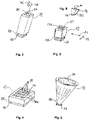
- Fig.2 Figure 12 shows a light tunnel 72 which does not fall within the scope of the invention. It has a square cross-section, and its four inner wall surfaces 74 are designed to absorb light.
- the entrance opening 721 of the light tunnel 72 can be seen at the upper end, and the light-sensitive sensor 73 is arranged at the lower end 722. In the figure, it is shown at a distance from the lower end 722 , which is not critical if little or no light falls on the light-sensitive surface of the sensor 73 which has not passed through the light tunnel 72 . Otherwise the sensor 73 is arranged directly on the light tunnel 72 .
- the optical axis OA is indicated here schematically. It can be seen that ambient light UL' can only pass through the light tunnel 72 from the entrance opening 721 to its end 722 if it falls parallel to the optical axis OA or only in a small angle range deviating from it.
- Fig.3 12 shows a light tunnel 72 according to another example, which has a partition wall 75.
- the partition wall 75 reduces the effective cross section of the light tunnel 72, as a result of which the angular range in which incident light can pass through the light tunnel 72 to the sensor 73 is reduced. In the present exemplary embodiment, this is used to shorten the length of the light tunnel 72 from its entrance opening 721 to the lower end 722 . Due to the shortening, the angular range increases again, which ultimately leads to an angular range comparable to that in Fig.2 illustrated light tunnel 72 leads. This applies to the angular range lying in a direction indicated by the double arrow P1.
- the shorter length of the light tunnel 72 increases the angular range under which the incident light reaches the sensor 73 .
- This takes into account an elongate shape of the display element 11, in which there is also a larger critical angle range in the direction of greater expansion, under which incident light can reach the display element 11 and thus damage it.
- the corresponding critical angle range is smaller in the direction of the shorter extent of the display element 11 .
- Fig.4 1 shows a light tunnel 72 according to an embodiment with a plurality of partition walls 75. Together with the wall surfaces 74, these form a multiplicity of small light tunnels 720 which have a small cross-section in comparison to their length.
- the light tunnel 72 of the Fig.4 is much shorter than the one to Fig.2 1, the small light tunnels 720 have a cross-sectional area to length ratio approximately equal to that of the light tunnel 72 of FIG Fig.2 .
- the light tunnel to Fig.2 and to Fig.4 thus have a comparable angular selectivity.
- the sensor 73 of the in Fig.4 The illustrated embodiment is attached directly to the lower end 722 of the light tunnel 72; only the light that has passed through the light tunnel 720 reaches it.
- FIG. 1 shows a light tunnel 72 with a conical wall 74 as a further example.
- the light tunnel 72 has the overall shape of a truncated cone, at the lower end 722 of which the light sensor 73 is arranged.
- the angular selectivity is achieved here by the opening angle of the cone.
- the light tunnel 72 is integrated into another component, for example the outer wall 76 of the head-up display, the light tunnel 72 ideally only consists of a recess in the outer wall 76 which then forms the wall surface 74 . This has the advantage that such a shape can easily be produced by injection molding or another method for producing plastic parts due to the cross section decreasing towards the inside.
- FIG. 12 shows, as a further example, a light tunnel 72 with conically inclined wall surfaces 74 which together result in a truncated cone with a square cross section.
- the sensor 73 is located at the lower end 722 of the light tunnel 72.
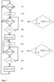
- Fig.7 shows a flowchart of a method. Alternative steps are shown in dashed lines.
- step S1 it is checked whether ambient light UL is incident in a critical angle range ⁇ +/- ⁇ around the critical angle ⁇ . If this is not the case, the process branches back to step S1. Otherwise, in step S2 it is checked whether the amount of light I(UL) incident in the critical angle range ⁇ +/- ⁇ exceeds a first limit value I1. If this is not the case, the process branches back to step S1. Otherwise it will Head-up display in step S3 moved from an operating position 21a to a parking position 21b.
- step S4 it is checked whether the amount of light I(UL) falls below a second limit value I2. If this is not the case, a branch is made back to step S4. Otherwise, in step S5, the head-up display is moved from the parking position 21b back to the operating position 21a. A branch is then made to step S1.
- Step S31 is also run through if the result of step S4 is negative. If this is positive and the time t that has elapsed since the setting to zero exceeds a second time t2, then step S5 follows, otherwise the process branches back to step S4. This prevents the parking position from being left if the light intensity I(UL) falls below the second limit value I2 for only a short time, for example because the vehicle drives under a gantry sign or the branch of a tree when the position of the sun remains the same, casting shadows for a short time.
- steps are implemented in the delay unit 41, for example.
- step S2 is replaced by step S20.
- step S20 the amount of light I(UL) is integrated over a period of time dt. If the integrated quantity of light exceeds the limit value I3, the process branches to step S21 or S3, otherwise to step S1. In this way, short-term fluctuations in the incident amount of light I (UL) are averaged out and do not lead to short-term jumps between the operating position 21a and the parking position 21b.
- step S4 is replaced by step S40.
- step S40 the amount of light I(UL) is integrated over a period of time dt. If the integrated quantity of light falls below the limit value I4, then a branch is made to step S41 or step S5, otherwise back to step S31 or to step S40. In this way, short-term fluctuations in the incident quantity of light I(UL) are averaged out and do not lead to short-term jumping between the operating position 21a and the parking position 21b.
- steps are implemented in the integration unit 42, for example.
- the idea of the present invention is to identify the critical angle ⁇ of the position of the sun. If this position of the sun S is maintained for a critical time, the head-up display is brought into a parking position 21b and switched off, so that the display element 11 cannot be damaged. The critical angle of the sun S is reached as soon as the sun's rays are parallel to the light path of the virtual image B. Then the light beams are reflected onto the display element 11 and rapidly heat it up. Detection of the critical angle ⁇ is achieved by a light tunnel 72 which only transmits light at that particular angle ⁇ .
- the head-up display is brought into the parking position 21b in order to protect the display element 11. As soon as the critical position is left again, the head-up display is activated again.
- the time that leads to a critical temperature on the display element 11 depends on the device. It is generally in the range of a few minutes. This depends, among other things, on the size of the mirrors 21, 22, their magnification factor and other passive countermeasures. These are, for example, the attachment of polarization filters or an additional coating of the mirrors 21,22.
- reaching the parking position is not time-critical, but only dependent on timely curtailment.
- One of the mirrors 21, 22 can be adjusted within a few seconds.
- An advantage of the measures according to the invention is that they are not permanently active, but only at a very specific position of the sun, at which the ambient light UL falls at the critical angle ⁇ , and this occurs over a certain period of time, which can lead to damage to the display element 11 .
Landscapes
- Physics & Mathematics (AREA)
- Engineering & Computer Science (AREA)
- General Physics & Mathematics (AREA)
- Optics & Photonics (AREA)
- Chemical & Material Sciences (AREA)
- Combustion & Propulsion (AREA)
- Transportation (AREA)
- Mechanical Engineering (AREA)
- Devices For Indicating Variable Information By Combining Individual Elements (AREA)
- Instrument Panels (AREA)
- Lighting Device Outwards From Vehicle And Optical Signal (AREA)
Description
- Die vorliegende Erfindung betrifft ein Head-Up-Display, bei dem eine Anzeigeeinheit vor Schädigung durch von außen einfallendes Licht geschützt ist sowie ein Verfahren zu dessen Betrieb.
- Ein Head-Up Display erzeugt in der Windschutzscheibe ein für den Fahrer sichtbares virtuelles Bild. Dieses Bild wird in der Regel auf einer Anzeigeeinheit, beispielsweise einer Flüssigkristallanzeige (LCD, Liquid Crystal Display) erzeugt und mittels Spiegeln durch ein Loch im Armaturenbrett an die Windschutzscheibe reflektiert. Oft werden Head-Up Displays durch aufwendige und teure Maßnahmen wie Polarisationsfolien, Kaltlichtspiegel und ähnliches, vor Sonneneinstrahlung geschützt, um vor allem die Anzeigeeinheit vor Überhitzung zu schützen. Als nachteilig ist daran anzusehen, daß die Kosten der Gegenmaßnahmen, insbesondere die Kosten für Polarisationsfolien oder Kaltlichtspiegel, recht hoch sind. Außerdem verzögern diese Maßnahmen die Beschädigung der Anzeigeeinheit nur für eine gewisse Zeit, vermeiden sie aber nicht gänzlich. Ein Nachteil bei der Verwendung von Gegenmaßnahmen die auf Polarisation beruhen, liegt darin, daß unangenehme Nebeneffekte auftreten, wie ein verschwindendes Bild wenn der Fahrer eine polarisierende Sonnenbrille verwendet. Polarisationsfolien, die auf dem Head-Up-Display angebracht sind, schimmern und werden daher oft als irritierend angesehen.
- Die
EP 2 843 652 A1 zeigt ein Head-Up-Display mit einem Anzeigeelement, dessen Bild mittels eines optischen Pfades in einem kritischen Winkel auf eine Spiegeleinheit eines Fahrzeugs geworfen, und von dort einem Umgebungsbild überlagert in Richtung Fahrer reflektiert wird. Dessen Anzeigeelement wird vor Schädigung durch direkt einfallendes Sonnenlicht geschützt, indem ein lichtempfindlicher Sensor das einfallende Sonnenlicht detektiert, und bei zu hoher Intensität die Leuchtstärke einer Beleuchtungseinheit für das Anzeigeelement reduziert oder die Beleuchtungseinheit ganz abschaltet. Dadurch wird die gesamte auf das Anzeigeelement einfallende Lichtmenge reduziert, was dessen Lebensdauer erhöht. Allerdings wird die Intensität des einfallenden Sonnenlichts nicht begrenzt, wodurch eine Schädigung des Anzeigeelements nur zeitlich hinausgeschoben, nicht aber unterbunden wird. - Aus der
US 2016/0306169 A1 ist ein Head-Up-Display bekannt, bei dem der Anstieg der Temperatur eines Anzeigeelements begrenzt wird. Dazu wird eine Abschätzung vorgenommen, ob der aktuelle Sonnenstand so ist, daß die Gefahr besteht, daß zu viel Sonnenlicht auf das Anzeigeelement fällt, dessen Temperatur dabei zu stark erhöht, und dieses dadurch geschädigt wird. In diesem Fall wird das auf das Anzeigeelement fallende Licht reduziert indem ein Filter in den optischen Pfad eingebracht wird. Als nachteilig daran ist anzusehen, daß die Abschätzung falsch sein kann, insbesondere wenn sie auf einer falsch bestimmten geographischen Position des Fahrzeugs beruht, einer falschen Tageszeit, oder wenn aufgrund der Witterung ohnehin kaum direktes Sonnenlicht auf das Anzeigeelement fällt. In diesem Fall reduziert der optische Filter auch die Lichtmenge des in Richtung Fahrer geleiteten Bildes des Head-Up-Displays, sodaß dieser grundlos auf ein optimal helles Bild der Anzeige verzichten muß. - Weitere Head-Up-Displays gemäß dem Stand der Technik sind aus den Druckschriften
US4886328 undDE102011105689 bekannt. - Wünschenswert ist ein zuverlässiger Schutz des Anzeigeelements eines Head-Up-Displays vor Schädigung durch Umgebungslicht, ohne den Betrieb des Head-Up-Displays unnötig einzuschränken. Wünschenswert ist weiterhin, dies möglichst kostengünstig zu erreichen.
- Erfindungsgemäß ist bei einem Head-Up-Display gemäß Oberbegriff des Anspruchs 1 vorgesehen, daß der Sensor Umgebungslicht detektiert, welches in einem kritischen Winkel von der Spiegeleinheit kommend in den optischen Pfad eintritt. Ein erfindungsgemäßes Head-Up-Display weist eine Steuerungseinheit auf, an deren Eingang das Signal des Sensors anliegt, und deren Steuerungsausgang mit einer Parkeinrichtung für das Head-Up-Display verbunden ist. Im Fall eines starken Lichteinfalls im kritischen Winkel wird dieser vom Sensor detektiert, woraufhin die Parkeinheit, von der Steuerungseinheit angesteuert, das Head-Up-Display in eine Parkposition fährt, in der das im kritischen Winkel einfallende Licht nicht auf das Anzeigeelement fällt. Als Anzeigeelement ist hier sowohl ein Flüssigkristallelement, auch LC-Display oder LCD genannt, vorgesehen, ein OLED-Element, welches organische Leuchtdioden aufweist, oder ein anderes Anzeigeelement, welches empfindlich auf bestimmte Frequenzen des einfallenden Lichts reagiert oder allgemein vor Überhitzung durch einfallendes Licht zu schützen ist. Als Spiegeleinheit wird im allgemeinen die Windschutzscheibe verwendet, oder ein sogenannter Combiner, ein teildurchlässiger Spiegel, der zwischen Fahrer und Windschutzscheibe angeordnet ist. Das Fahrzeug kann sowohl als Land-, als Wasserals auch als Luftfahrzeug vorgesehen sein. Der Fahrer, in dessen Richtung das dem Umgebungsbild überlagerte Bild des Anzeigeelements geleitet wird, ist vorzugsweise der Lenker des Fahrzeugs. Das überlagerte Bild kann hier aber auch zusätzlich oder alternativ für den Beifahrer oder einen anderen Mitfahrer des Fahrzeugs vorgesehen sein. Der Sensor ist ein winkelabhängiger Sensor, der Umgebungslicht detektiert welches im kritischen Winkel von der Spiegeleinheit kommend in den optischen Pfad eintritt. Umgebungslicht, welches in diesem Winkel und einem um diesen herumliegenden Winkelbereich einfällt, gelangt in der Betriebsposition des Head-Up-Displays vollständig oder zu großen Teilen auf das Anzeigeelement und führt dabei bei längerer Einwirkung oder auch bei kurzfristig sehr hoher Intensität zu dessen Schädigung. Das Head-Up-Display wird daher bei in diesem kritischen Winkelbereich einfallenden Umgebungslicht in eine Parkposition versetzt. Schädigendes Umgebungslicht ist im allgemeinen direkt einfallendes Sonnenlicht, es kann aber auch von anderen starken Lichtquellen herrühren, die das Anzeigeelement zu stark erhitzen oder auf andere Art und Weise schädigen. Dies sind beispielsweise starke künstliche Lichtquellen der Straßenbeleuchtung, die bei Langsamfahrt oder Stillstand des Fahrzeugs für längere Zeit im kritischen Winkel einfallen. Die Parkposition des Head-Up-Displays wird durch Schließen eines Deckels des Head-Up-Displays erreicht, wodurch der Strahlengang unterbrochen wird. Auch andere Mittel, die zum Unterbrechen des Strahlengangs geeignet sind, finden erfindungsgemäß Verwendung. So unterbricht auch ein Verkippen der Spiegeleinheit oder eines anderen im Strahlengang befindlichen Spiegels den Strahlengang und verhindert, daß im kritischen Winkelbereich einfallendes Licht auf das Anzeigeelement gelangt.
- Ein erfindungsgemäßes Head-Up-Display gemäß Anspruch 1 weist einen Lichttunnel auf, der entsprechend dem kritischen Winkel ausgerichtet ist, und an dessen Ende der Sensor angeordnet ist. Dies stellt sicher, daß nur solches Licht vom Sensor registriert wird, welches im kritischen Winkel bzw. im kritischen Winkelbereich einfällt. Der Sensor selbst braucht daher keine spezielle winkelabhängige Ausgestaltung aufzuweisen, er ist somit einfach im Aufbau und kostengünstig. Der Lichttunnel wird kostengünstig in das Gehäuse des Head-Up-Displays oder ein anderes Bauteil des Head-Up-Displays integriert, beispielsweise in ein im Spritzgießverfahren hergestelltes Kunststoffbauteil.
- Gemäß einer vorteilhaften Ausgestaltung weist der Lichttunnel eine oder mehrere absorbierende Wandflächen auf seiner Innenseite auf. Dies bewirkt, daß nur Licht, das im kritischen Winkel einfällt, den Tunnel geradlinig passiert, während außerhalb des kritischen Winkelbereichs einfallendes Licht von den Wandflächen absorbiert und somit nicht vom Sensor detektiert wird.
- Eine oder mehrere kegelförmig geneigte Wandflächen ermöglichen eine Erweiterung des kritischen Winkels auf einen kritischen Winkelbereich, beispielsweise auf +/-5° Abweichung vom kritischen Winkel, in dem ebenfalls in zu hoher Intensität einfallendes Umgebungslicht zu einer Schädigung des Anzeigeelements führt. Der Lichttunnel ist dazu beispielsweise als Rundkegel, also mit einer einzigen kegelförmig geneigten Wandfläche ausgestaltet. Mehrere kegelförmig geneigte Wandflächen bilden die Oberfläche eines Kegels mit nichtrundem Querschnitt, beispielsweise einem viereckigen oder sechseckigen Querschnitt, oder auch einen unregelmäßig geformten Querschnitt. Derartige von einem Rundkegel abweichende Formen sind geeignet, um den vom Sensor detektierten kritischen Winkelbereich an die geometrische Form des Anzeigeelements anzupassen.
- Eine oder mehrere zwischen den Wandflächen des Lichttunnels angeordnete Trennflächen, die im wesentlichen parallel zu den Wandflächen ausgerichtet sind, führen ebenfalls dazu, daß nur Licht aus dem kritischen Winkel bzw. kritischen Winkelbereich auf das Sensorelement fällt, selbst wenn der Querschnitt des Lichttunnels relativ groß gewählt ist oder seine Länge im Vergleich zum Querschnitt relativ kurz ist. Durch die Wandflächen werden in diesem Fall viele kleine Lichttunnel gebildet, die ebenfalls trotz eines ungünstigen Verhältnisses zwischen Länge und Querschnitt des Lichttunnels eine hohe Winkelselektivität gewährleisten. Im allgemeinen werden mehrere Trennflächen verwendet, bei großer Länge und vergleichsweise kleinem Querschnitt des Lichttunnels kann aber auch schon eine Trennfläche zur Erzielung der gewünschten Winkelselektivität ausreichend sein. Weist der Lichttunnel kegelförmig geneigte Wandflächen auf, so sind die Trennflächen vorzugsweise auf denselben Fluchtpunkt wie die Wandflächen des Trichters ausgerichtet.
- Erfindungsgemäß ist vorgesehen daß der Lichttunnel an einem Gehäuse des Head-Up-Displays in der Nähe der Lichtausgangsöffnung des Strahlengangs angeordnet ist. Dies hat den Vorteil, daß der kritische Winkel hier noch einfach feststellbar ist, und noch keine Beeinflussung durch im Inneren des Head-Up-Displays angeordnete Elemente auftritt, die eine Ausrichtung des Lichttunnels im korrekten Winkel erschwert. Der Lichttunnel ist vorzugsweise einstückig mit dem Gehäuse ausgebildet, beispielsweise als Kunststoffteil, welches gleichzeitig mit dem Gehäuse im Spritzgußverfahren hergestellt wird, oder als separates Bauteil, welches in das Gehäuse bei dessen Herstellung eingespritzt oder in eine Gehäuseöffnung eingesetzt wird.
- Erfindungsgemäß ist vorgesehen, daß die Steuerungseinheit eine Verzögerungseinheit und alternativ dazu oder zusätzlich eine Integrationseinheit aufweist. Die Verzögerungseinheit führt dazu, daß eine nur kurzzeitige Überschreitung eines Schwellwerts der Intensität des im kritischen Winkel einfallenden Lichts nicht dazu führt, daß die Parkposition eingenommen wird. Dies hat den Vorteil, daß beispielsweise bei kurzzeitigem Überfahren einer Bodenwelle, dem schnellen Durchfahren einer Kurve, bei Reflexion des Sonnenlichts an einem außerhalb des Fahrzeugs befindlichen spiegelnden Element, beispielsweise den Glasflächen eines Hauses, an dem das Fahrzeug vorbeifährt, keine Unterbrechung des für den Fahrer sichtbaren Bildes der Anzeige des Anzeigeelements auftritt. Bei derartig kurzzeitig auftretenden hohen Lichtintensitäten tritt nur eine geringe Erwärmung des Anzeigeelements auf, die nur zu einer geringfügigen bzw. zu keiner Schädigung des Anzeigeelements führt. Anstatt oder zusätzlich zur Verzögerungseinheit ist eine Integrationseinheit vorgesehen, die die Intensität des Lichteinfalls über einen gewissen Zeitraum integriert, und dazu führt, daß die Parkposition nur dann eingenommen wird, wenn eine gewisse Gesamtenergie innerhalb eines gewissen kritischen Zeitraums eingefallen ist. Sie gibt die Parkposition wieder frei, wenn die Gesamtenergie wieder die innerhalb einer kritischen Zeitspanne eingefallene Gesamtenergie wieder unter einen kritischen Wert gefallen ist. Dies ist zum Beispiel dann sinnvoll, wenn eine Baumallee durchfahren wird, bei der aufgrund der Lücken zwischen den Blättern nur jeweils kurzfristig eine hohe Lichtintensität auf den Sensor fällt, die über eine größeren Zeitraum aber dennoch zu einer kritischen Erwärmung oder anderweitig hervorgerufenen Schädigung des Anzeigeelements führt.
- Erfindungsgemäß ist vorgesehen, daß der Lichttunnel eine Länge aufweist, die ein mehrfaches seines Durchmessers beträgt. Ein solcher Lichttunnel mit im Vergleich zu seinem Querschnitt großer Länge hat den Vorteil einer guten Winkelselektivität.
- Gemäß der Erfindung weist das Head-Up-Display mehrere Trennwände auf, die eine Vielzahl von kleinen Lichttunneln mit im Vergleich zu ihrer Länge kleinem Querschnitt bilden. Dies kombiniert vorteilhaft gute Winkelselektivität mit kurzer Baulänge.
- Erfindungsgemäß sind eine kegelförmige Wandfläche und geneigte Trennflächen vorgesehen, die alle auf denselben Fluchtpunkt ausgerichtet sind. Im oder nahe dem Fluchtpunkt befindet sich ein Sensor. Dies hat den Vorteil, daß Licht aus einem durch die Kegelform bedingten Winkelbereich berücksichtigt wird.
- Vorteilhafterweise ist der Lichttunnel ein in ein Gehäuse des Head-Up-Displays eingespritztes Bauteil. Dieses wird mit geeigneter Genauigkeit vorgefertigt. Beim Einspritzen in das Gehäuse reichen dann geringere Genauigkeitsanforderungen aus.
- Weist der Lichttunnel einen quadratischen Querschnitt auf, so hat dies den Vorteil, einer unkomplizierten Herstellung auf. Weist er einen rechteckigen Querschnitt auf, so hat dies den zusätzlichen Vorteil, daß der Lichttunnel an die oftmals verwendete längliche Form des Anzeigeelements angepaßt ist.
- Erfindungsgemäß ist der Lichttunnel durch eine Ausnehmung in einer Außenwand des Head-Up-Displays gebildet. Dies hat den Vorteil einer leichten Anpaßbarkeit an bereits bestehende Produktdesigns, die nur leicht abgeändert zu werden brauchen um die erfindungsgemäße Lösung zu implementieren.
- Gemäß einer weiteren Ausbildungsform der Erfindung weist der Lichttunnel kegelförmig geneigte Wandflächen auf, die einen Kegelstumpf mit quadratischem Querschnitt bilden.
- Ein Verfahren zum Betreiben eines Head-Up-Displays weist folgende Schritte auf: Umgebungslicht, das in einem kritischen Winkelbereich in das Head-Up-Display einfällt, wird detektiert. Überschreitet die Intensität des im kritischen Winkelbereich einfallenden Lichts einen ersten Grenzwert, so wird das Head-Up-Display aus einer Betriebsposition in eine Parkposition versetzt. Unterschreitet die Intensität des im kritischen Winkelbereich einfallenden Lichts einen zweiten Grenzwert, so wird das Head-Up-Display aus der Parkposition wieder in eine Betriebsposition versetzt. Das Überschreiten des ersten Grenzwerts liegt dann vor, wenn das Sensorsignal einen gewissen Wert überschreitet, unabhängig davon wie lange dieser gewisse Wert überschritten wird. Alternativ liegt eine Überschreitung des Grenzwerts dann vor, wenn das Sensorsignal für mehr als eine bestimmte Zeit einen gewissen Wert überschreitet. Alternativ ist vorgesehen, das Sensorsignal über ein Zeitfenster zu integrieren und die Parkposition dann einzunehmen, wenn das integrierte Signal einen bestimmten Wert überschreitet. Der zweite Grenzwert ist vorzugsweise niedriger als der erste Grenzwert.
- Weitere vorteilhafte Ausgestaltungen der Erfindung sind auch in der nachfolgenden Beschreibung von Ausführungsbeispielen anhand von Figuren angegeben. Sinnvolle Kombinationen und Weiterbildungen, die im Können des Fachmanns liegen, liegen ebenfalls im Bereich der Erfindung.
- Es zeigen:
- Fig.1
- Head-Up-Display
- Fig.2
- Lichttunnel
- Fig.3
- Lichttunnel mit Trennwand
- Fig.4
- Lichttunnel mit Trendwänden
- Fig.5
- Lichttunnel mit kegelförmiger Wandfläche
- Fig.6
- Lichttunnel mit kegelförmigen Wandflächen
- Fig.7
- Flußdiagramm eines Verfahrens
-
Fig.1 zeigt ein erfindungsgemäßes Head-Up-Display. Auf einem Anzeigeelement 11 einer Anzeigeeinheit 1 wird ein darzustellendes Bild B angezeigt. Das Anzeigeelement 11 ist hier ein Flüssigkristall-Anzeigeelement, welches von einer Lichtquelle 5 hinterleuchtet wird und von einer Steuerungseinheit 4 ein Signal für das darzustellende Bild B erhält. Das darzustellende Bild B erscheint dem Fahrer als virtuelles Bild VB im Außenraum vor dem Fahrzeug zu schweben. Tatsächlich geht sein Blick BL1 nicht über den Blick BL2 auf das vor dem Fahrzeug dargestellte virtuelle Bild VB, sondern, an der Windschutzscheibe 31 gespiegelt über BL3, BL4 und BL5 auf das Anzeigeelement 11. Der Blick BL verläuft dabei entgegengesetzt zum Strahlengang des vom Anzeigeelement 11 ausgehenden Lichts. Dieses wird, vom Anzeigeelement 11 kommend, an einem verstellbaren Spiegel 21 reflektiert, von diesem auf einen gekrümmten Spiegel 22 geworfen und von diesem auf die Windschutzscheibe 31 reflektiert, von wo sie in das Auge 61 des Fahrers fällt. Da die Windschutzscheibe 31 teilweise reflektieren und teilweise durchlässig ist, wird dabei das Bild B als virtuelles Bild VB dem durch die Windschutzscheibe 31 fallenden Umgebungsbild UB überlagert. Die Krümmung des gekrümmten Spiegels 22 kompensiert die Krümmung der Windschutzscheibe 31, sodaß das Auge 61 des Fahrers ein unverzerrtes Bild B wahrnimmt. Der verstellbare Spiegel 21 und der gekrümmte Spiegel 22 sind Teil einer Ablenkeinheit 2, die den optischen Pfad zwischen Anzeigeelement 11 und Ausgangsöffnung 7 des Head-Up-Displays bildet. Der verstellbare Spiegel 21 wird mittels eines Antriebs 211 verstellt. Beide zusammen bilden die Parkeinrichtung 20. - Die optische Achse OA3 des aus der Ausgangsöffnung 7 austretenden Lichts weist einen kritischen Winkel α zur Senkrechten auf. In einer Ebene senkrecht zur Zeichenebene steht die optische Achse OA3 im allgemeinen senkrecht. Abhängig von der Fahrzeuggeometrie, der Anordnung des Head-Up-Displays und anderen Faktoren, kann hier aber auch ein von 90° verschiedener kritischer Winkel auftreten. Im folgenden wird nur der in der Zeichenebene liegende kritische Winkel α berücksichtigt, ein in einer senkrecht zur Zeichenebene stehenden Ebene liegender kritischer Winkel ist erfindungsgemäß entsprechend zu berücksichtigen. Im folgenden wird der Einfachheit halber vom Winkel α gesprochen obwohl es sich tatsächlich um einen relativ schmalen Winkelbereich sowohl in der Zeichenebene als auch in einer senkrecht zu dieser stehenden Ebene handelt. Dieser Winkelbereich müßte mit αx +/- Δx und αy +/- Δy beschrieben werden, wobei x und y zueinander orthogonale Richtungen beschreiben.
- Das von der Sonne S kommende Umgebungslicht UL fällt in der Abbildung im kritischen Winkel α durch die Ausgangsöffnung 7 in die Ablenkeinheit 2. Es gelangt damit auf das Anzeigeelement 11 und schädigt dieses dabei durch Überhitzung oder andere, von starkem Lichteinfall hervorgerufene Beschädigungen. Um dies zu verhindern, wird der verstellbare Spiegel 21 von seiner dargestellten Betriebsposition 21a in eine gestrichelt dargestellte Parkposition 21b verschwenkt. Auch eine Verschwenkung in die andere Richtung, um eine hier nicht dargestellte alternative Parkposition einzunehmen, ist hier sinnvoll möglich. Dies trifft auch auf ein Verschwenken um eine Achse, die nicht wie die hier dargestellte Achse senkrecht zur Zeichenebene steht. Befindet sich der verstellbare Spiegel 21 in seiner Parkposition 21b, so fällt kein Umgebungslicht UL mehr auf das Anzeigeelement 11. Alternativ oder zusätzlich kann auch der gekrümmte Spiegel 22 von seiner hier dargestellten Betriebsposition in eine hier nicht dargestellte Parkposition verschwenkt werden. Auch das Verschließen der Ausgangsöffnung 7 mittels eines Deckels 71, der hier in der Betriebsposition dargestellt ist, versetzt das Head-Up-Display in eine Parkposition. Ein anderes, den Strahlengang unterbrechendes Element, ähnlich dem Deckel 71, kann auch an anderer Stelle innerhalb des Head-Up-Displays angeordnet sein. Das Umgebungslicht UL fällt auch als Umgebungslicht UL' in den Lichttunnel 72 ein, an dessen der Eingangsöffnung 721 entgegengesetztem Ende 722 ein lichtempfindlicher Sensor 73 angeordnet ist. Dessen Ausgangssignal LS wird einem Steuerungseingang 401 der Steuerungseinheit 41 zugeführt. Während der größten Zeit des Betriebs des Head-Up-Displays befindet sich die Sonne S in einer anderen Position als der dargestellten kritischen Position, bei der das Umgebungslicht UL' im kritischen Winkel α einfällt. Steht die Sonne S in einer anderen als der hier dargestellten kritischen Position, so kann das von der Sonne S kommende Umgebungslicht UL' den Lichttunnel 72 nicht passiert, sondern wird meist bereits in dessen oberem Bereich an einer Wandfläche 74 an der Innenseite des Lichttunnels 72 absorbiert. Der Sensor 73 gibt daher im Normalfall nur ein sehr kleines Ausgangssignal LS ab. Befindet sich die Sonne S aber in einer Position, in der das von ihr kommende Umgebungslicht UL' im kritischen Winkel α einfällt, so fällt dieses parallel zum Lichttunnel 72 ein, durchläuft diesen und löst im Sensor 73 ein großes Ausgangssignal LS aus. Dieses wird von der Steuerungseinheit 4 in ein an ihrem Steuerungsausgang 402 abgegebenes Parksignal PS umgesetzt, welches einen Antrieb 211 des verstellbaren Spiegels 21 ansteuert. Dieser verschwenkt daraufhin den verstellbaren Spiegel 21 von der Betriebsposition 21a in seiner Parkposition 21b. Im dargestellten Ausführungsbeispiel weist die Steuerungseinheit 4 sowohl eine Verzögerungseinheit 41 als auch eine Integrationseinheit 42 auf. Die Verzögerungseinheit 41 dient dazu, das Verschwenken des Spiegels 21 verzögert auszulösen, dies vermeidet, daß bereits bei kurzzeitigen Spitzen im Ausgangssignal LS ein Verschwenken stattfindet. Die Integrationseinheit 42 ermittelt die über einen gewissen Zeitraum einfallende Lichtmenge, und löst ein Verschwenken nur dann aus, wenn eine bestimmte Lichtmenge pro Zeiteinheit überschritten beziehungsweise unterschritten wurde.
-
Fig.2 zeigt einen Lichttunnel 72, der nicht unter den erfindungsgemäßen Gegenstand fällt. Er weist einen quadratischen Querschnitt auf, seine innenliegenden vier Wandflächen 74 sind lichtabsorbieren ausgelegt. Am oberen Ende sieht man die Eingangsöffnung 721 des Lichttunnels 72, am unteren Ende 722 ist der lichtempfindliche Sensor 73 angeordnet. In der Abbildung ist er vom unteren Ende 722 beabstandet dargestellt, was dann unkritisch ist, wenn kein oder kaum Licht auf die lichtempfindliche Fläche des Sensors 73 fällt, welches nicht den Lichttunnel 72 durchlaufen hat. Andernfalls wird der Sensor 73 direkt am Lichttunnel 72 angeordnet. Die optische Achse OA ist hier schematisch angedeutet. Man erkennt, daß Umgebungslicht UL' nur dann den Lichttunnel 72 von der Eingangsöffnung 721 bis zu seinem Ende 722 durchlaufen kann, wenn es parallel zur optischen Achse OA oder nur in einem kleinen davon abweichenden Winkelbereich einfällt. -
Fig.3 zeigt einen Lichttunnel 72 gemäß eines weiteren Beispiels, der eine Trennwand 75 aufweist. Durch die Trennwand 75 verringert sich der effektive Querschnitt des Lichttunnels 72, wodurch der Winkelbereich, in dem einfallendes Licht den Lichttunnel 72 bis zum Sensor 73 passieren kann, reduziert wird. Dies wird im vorliegenden Ausführungsbeispiel dazu genutzt, die Länge des Lichttunnels 72 von seiner Eingangsöffnung 721 bis zum unteren Ende 722 zu verkürzen. Durch die Verkürzung vergrößert sich der Winkelbereich wieder, was im Endeffekt zu einem vergleichbaren Winkelbereich wie zu dem inFig.2 dargestellten Lichttunnel 72 führt. Dies trifft für den in einer durch den Doppelpfeil P1 angedeuteten Richtung liegenden Winkelbereich zu. Entsprechend einer durch den Doppelpfeil P2 angedeuteten Richtung vergrößert sich durch die kürzere Länge des Lichttunnels 72 der Winkelbereich unter dem einfallendes Licht bis zum Sensor 73 gelangt. Dies berücksichtigt eine längliche Form des Anzeigeelements 11, bei welchem in Richtung der größeren Ausdehnung auch ein größerer kritischer Winkelbereich vorhanden ist unter dem einfallendes Licht das Anzeigeelement 11 erreichen und somit schädigen kann. In Richtung der kürzeren Ausdehnung des Anzeigeelements 11 ist der entsprechende kritische Winkelbereich kleiner. -
Fig.4 zeigt einen Lichttunnel 72 gemäß einer Ausgestaltungsform mit mehreren Trennwänden 75. Diese bilden zusammen mit den Wandflächen 74 eine Vielzahl von kleinen Lichttunneln 720, die einen im Vergleich zu ihrer Länge kleinen Querschnitt aufweisen. Obwohl der Lichttunnel 72 derFig.4 wesentlich kürzer ist als der zuFig.2 gezeigte, liegt das Verhältnis von Querschnittsfläche zu Länge bei den kleinen Lichttunneln 720 in etwa gleichauf mit dem des Lichttunnels 72 derFig.2 . Die Lichttunnel zuFig.2 und zuFig.4 weisen somit eine vergleichbare Winkelselektivität auf. Der Sensor 73 des inFig.4 dargestellten Ausführungsbeispiels ist direkt am unteren Ende 722 des Lichttunnels 72 befestigt, ihn erreicht nur das Licht, das die Lichttunnel 720 durchlaufen hat. -
Fig.5 zeigt als weiteres Beispiel einen Lichttunnel 72 mit kegelförmiger Wand 74. Der Lichttunnel 72 hat insgesamt die Form eines abgeschnittenen Kegels, an dessen unterem Ende 722 der Lichtsensor 73 angeordnet ist. Die Winkelselektivität wird hier durch den Öffnungswinkel des Kegels erreicht. Befindet sich der Lichttunnel 72 integriert in ein weiteres Bauteil, beispielsweise die Außenwand 76 des Head-Up-Displays, so besteht der Lichttunnel 72 im Idealfall nur aus eine Ausnehmung in der Außenwand 76, die dann die Wandfläche 74 bildet. Dies hat den Vorteil, daß eine derartige Form aufgrund des nach innen hin abnehmenden Querschnitts leicht im Spritzgußverfahren oder einem anderen Verfahren zur Herstellung von Kunststoffteilen hergestellt werden kann. -
Fig.6 zeigt als weiteres Beispiel einen Lichttunnel 72 mit kegelförmig geneigten Wandflächen 74, die zusammen einen Kegelstumpf mit quadratischem Querschnitt ergeben. Am unteren Ende 722 des Lichttunnels 72 befindet sich der Sensor 73. -
Fig.7 zeigt ein Flußdiagramm eines Verfahrens. Dabei sind alternative Schritte gestrichelt dargestellt. Im Schritt S1 wird überprüft, ob Umgebungslicht UL in einem kritischen Winkelbereich α +/- Δ um den kritischen Winkel α einfällt. Ist dies nicht der Fall, so wird zu Schritt S1 zurückverzweigt. Andernfalls wird in Schritt S2 geprüft, ob die im kritischen Winkelbereich α +/- Δ einfallende Lichtmenge I(UL) einen ersten Grenzwert I1 überschreitet. Ist dies nicht der Fall, so wird zu Schritt S1 zurückverzweigt. Andernfalls wird das Head-Up-Display im Schritt S3 von einer Betriebsposition 21a in eine Parkposition 21b versetzt. - Im Schritt S4 wird geprüft, ob die Lichtmenge I(UL) einen zweiten Grenzwert I2 unterschreitet. Ist dies nicht der Fall, so wird zu Schritt S4 zurückverzweigt. Andernfalls wird im Schritt S5 das Head-Up-Display von der Parkposition 21b zurück in die Betriebsposition 21a versetzt. Anschließend wird zu Schritt S1 verzweigt.
- In einer alternativen Variante wird im zusätzlichen Schritt S11, der sich an den Schritt S1 bei positivem Ergebnis anschließt, ein Zähler auf t=0 gesetzt. Übertrifft die Lichtmenge I (UL) den ersten Grenzwert I1, aber die Zeit t noch nicht eine erste Zeit t1, so wird zu Schritt S2 zurückverzweigt, andernfalls zu Schritt S3. Auf diese Weise wird ausgeschlossen, daß die Parkposition 21b auch dann eingenommen wird, wenn die im kritischen Winkelbereich einfallende Lichtmenge I(UL) nur kurzzeitig den ersten Grenzwert I1 überschreitet. Diese Schritte werden beispielsweise in der Verzögerungseinheit 41 realisiert.
- In einer alternativen Variante wird im zusätzlichen Schritt S31, der sich an den Schritt S3 anschließt, ein Zähler auf t = 0 gesetzt. Der Schritt S31 wird auch dann durchlaufen, wenn das Ergebnis des Schritts S4 negativ ist. Ist dieses positiv und überschreitet die seit dem Nullsetzen abgelaufene Zeit t eine zweite Zeit t2, so folgt Schritt S5, andernfalls wird zu Schritt S4 zurückverzweigt. Auf diese Weise wird verhindert, daß die Parkposition verlassen wird wenn die Lichtintensität I(UL) nur kurzfristig den zweiten Grenzwert I2 unterschreitet, beispielsweise weil bei gleichbleibendem Sonnenstand eine Schilderbrücke oder der Ast eines Baumes vom Fahrzeug unterfahren werden, und dabei kurzfristig Schatten werfen. Diese Schritte werden beispielsweise in der Verzögerungseinheit 41 realisiert.
- In einer weiteren alternativen Variante wird der Schritt S2 durch den Schritt S20 ersetzt. Im Schritt S20 wird die Lichtmenge I(UL) über einen Zeitraum dt integriert. Übertrifft die integrierte Lichtmenge den Grenzwert I3, so wird zu Schritt S21 bzw. S3 verzweigt, andernfalls zu Schritt S1. Auf diese Weise werden kurzfristige Schwankungen in der einfallenden Lichtmenge I (UL) weggemittelt und führen nicht zu kurzfristigen Sprüngen zwischen Betriebsposition 21a und Parkposition 21b. Diese Schritte werden beispielsweise in der Integrationseinheit 42 realisiert.
- In einer weiteren alternativen Variante wird der Schritt S4 durch den Schritt S40 ersetzt. Im Schritt S40 wird die Lichtmenge I(UL) über einen Zeitraum dt integriert. Unterschreitet die integrierte Lichtmenge den Grenzwert I4, so wird zu Schritt S41 bzw. Schritt S5 verzweigt, andernfalls zurück zu Schritt S31 oder zu Schritt S40. Auf diese Weise werden kurzfristige Schwankungen in der einfallenden Lichtmenge I(UL) weggemittelt und führen nicht zu kurzfristigem Springen zwischen Betriebsposition 21a und Parkposition 21b. Diese Schritte werden beispielsweise in der Integrationseinheit 42 realisiert.
- In anderen Worten besteht die Idee der vorliegenden Erfindung darin, den kritischen Winkel α des Sonnenstandes zu identifizieren. Falls diese Position der Sonne S über eine kritische Zeit hinweg eingehalten wird, wird das Head-Up-Display in eine Parkposition 21b gebracht und ausgeschaltet, sodaß keine Schädigung des Anzeigeelements 11 möglich ist. Der kritische Winkel der Sonne S ist erreicht, sobald die Sonnenstrahlen parallel zum Lichtpfad des virtuellen Bildes B verlaufen. Dann werden die Lichtstrahlen auf das Anzeigeelement 11 reflektiert und erhitzen dieses rasant. Die Detektion des kritischen Winkels α wird durch einen Lichttunnel 72 erzielt, der nur Licht in diesem speziellen Winkel α durchläßt. Wenn der lichtempfindliche Sensor 73 am Ende des Lichttunnels 72 über eine kritische Zeitspanne hinweg aktiviert wird, wird das Head-Up-Display in die Parkposition 21b gebracht, um das Anzeigeelement 11 zu schützen. Sobald die kritische Position wieder verlassen wird, wird das Head-Up Display wieder aktiviert. Die Zeit, die zu einer kritischen Temperatur auf dem Anzeigeelement 11 führt, ist geräteabhängig. Sie liegt im allgemeinen im Bereich weniger Minuten. Dies hängt unter anderem ab von der Größe der Spiegel 21,22, von deren Vergrößerungsfaktor und von weiteren passiven Gegenmaßnahmen. Dies sind beispielsweise das Anbringen von Polarisationsfiltern oder eine zusätzliche Beschichtung der Spiegel 21,22. Somit ist das Erreichen der Parkposition nicht zeitkritisch, sondern nur abhängig von einer rechtzeitigen Abregelung. Eine Verstellung eines der Spiegel 21,22 ist innerhalb weniger Sekunden realisierbar.
- Bei diesem Vorgehen wird auf schon existierende Elemente eines typischen Head-Up-Displays zurückgegriffen. Durch geschickte Positionierung des Lichttunnels 72 in der Nähe des Lichtpfades sind keine zusätzlichen Bauteile oder Sicherungsmaßnahmen nötig. Ein Lichtsensor und eine Parkposition 21b werden für andere Funktionen des Head-Up-Displays bereits verwendet. Ein zusätzliches Teil ist der Lichttunnel 72, welcher konstruktiv in bestehenden Bauteilen integriert werden kann. Der bereits bisher verwendete Lichtsensor mißt die Umgebungshelligkeit, um die Helligkeit der Lichtquelle 5 automatisch anzupassen. Falls der bisher vorhandene Lichtsensor nicht verwendbar ist, wird ein zweiter, einfacher Sensor 73 benötigt.
- Ein Vorteil der erfindungsgemäßen Maßnahmen besteht darin, daß sie nicht dauerhaft aktiv sind, sondern nur bei einem ganz speziellen Sonnenstand, bei dem das Umgebungslicht UL im kritischen Winkel α einfällt, und dies über eine gewisse Zeit erfolgt, was zur Schädigung des Anzeigeelements 11 führen kann.
- Es liegt im Können des Fachmanns, eine oder mehrere der genannten Maßnahmen abzuändern oder in anderer Kombination einzusetzen, sofern diese unter den Gegenstand des Anspruchs 1 fallen, auch wenn diese nicht explizit hier beschrieben sind.
Claims (11)
- Head-Up-Display mit einem Anzeigeelement (11), dessen Bild (B) mittels einer Ablenkeinheit (2) entlang einer optischen Achse (OA3) auf eine Spiegeleinheit eines Fahrzeugs geworfen wird, und von dort einem Umgebungsbild (UB) überlagert in Richtung Auge (61) eines Fahrers reflektiert wird, und einem lichtempfindlichen Sensor (73), wobei der Sensor (73) Umgebungslicht (UL') detektiert, welches parallel zur optischen Achse oder nur in einem kleinen davon abweichenden Winkelbereich von der Spiegeleinheit (3) kommend in die Ablenkeinheit (2) eintritt, und das Head-Up-Display eine Steuerungseinheit (4) aufweist, an deren Steuerungseingang (401) ein Signal (LS) des Sensors (73) anliegt, und deren Steuerungsausgang (402) mit einer Parkeinrichtung (20) für das Head-Up-Display verbunden ist, wobei das Head-Up-Display einen Lichttunnel (72) aufweist, der von der optischen Achse (OA3) beabstandet und parallel zu dieser ausgerichtet ist, und an dessen Ende (722) der Sensor (73) angeordnet ist, dadurch gekennzeichnet, daß der Lichttunnel (72) mehrere Trennwände (75) aufweist, die eine Vielzahl von kleinen Lichttunneln (720) mit im Vergleich zu ihrer Länge kleinem Querschnitt bilden.
- Head-Up-Display nach Anspruch 1, dadurch gekennzeichnet, daß der Lichttunnel (72) aufweist:- zumindest eine absorbierende Wandfläche (74) und/oder- zumindest eine kegelförmig geneigte Wandflächen (74) und/oder- zumindest eine zwischen den Wandflächen (74) angeordnete Trennwand (75), die im wesentlichen parallel zu zumindest einer Wandfläche (74) ausgerichtet ist.
- Head-Up-Display nach Anspruch 1 oder 2, dadurch gekennzeichnet, daß der Lichttunnel (72) an einem Gehäuse (70) des Head-Up-Displays in der Nähe einer Ausgangsöffnung (7) der Ablenkeinheit (2) angeordnet ist.
- Head-Up-Display nach einem der vorhergehenden Ansprüche, dadurch gekennzeichnet, daß die Steuerungseinheit (4) eine Verzögerungseinheit (41) und/oder eine Integrationseinheit (42) aufweist.
- Head-Up-Display nach einem der vorhergehenden Ansprüche, dadurch gekennzeichnet, daß der Lichttunnel (72) eine Länge aufweist, die ein mehrfaches seines Durchmessers beträgt.
- Head-Up-Display nach einem der vorhergehenden Ansprüche, dadurch gekennzeichnet, daß es eine kegelförmige Wandfläche (74) und geneigte Trennflächen aufweist, die alle auf denselben Fluchtpunkt ausgerichtet sind.
- Head-Up-Display nach einem der vorhergehenden Ansprüche, dadurch gekennzeichnet, daß der Lichttunnel (72) ein in ein Gehäuse (70) des Head-Up-Displays eingespritztes Bauteil ist.
- Head-Up-Display nach einem der vorhergehenden Ansprüche, dadurch gekennzeichnet, daß der Lichttunnel (72) einen quadratischen Querschnitt aufweist.
- Head-Up-Display nach einem der vorhergehenden Ansprüche, dadurch gekennzeichnet, daß der Lichttunnel (72) einen rechteckigen Querschnitt aufweist.
- Head-Up-Display nach Anspruch 1, dadurch gekennzeichnet, daß der Lichttunnel (72) durch eine Ausnehmung in einer Außenwand (76) des Head-Up-Displays gebildet ist.
- Head-Up-Display nach Anspruch 1, dadurch gekennzeichnet, daß der Lichttunnel (72) kegelförmig geneigte Wandflächen (74) aufweist, die einen Kegelstumpf mit quadratischem Querschnitt bilden.
Applications Claiming Priority (2)
| Application Number | Priority Date | Filing Date | Title |
|---|---|---|---|
| DE102017206805.1A DE102017206805A1 (de) | 2017-04-24 | 2017-04-24 | Head-Up-Display |
| PCT/EP2018/060297 WO2018197391A1 (de) | 2017-04-24 | 2018-04-23 | Head-up-display |
Publications (2)
| Publication Number | Publication Date |
|---|---|
| EP3615984A1 EP3615984A1 (de) | 2020-03-04 |
| EP3615984B1 true EP3615984B1 (de) | 2023-02-22 |
Family
ID=62116835
Family Applications (1)
| Application Number | Title | Priority Date | Filing Date |
|---|---|---|---|
| EP18722927.3A Active EP3615984B1 (de) | 2017-04-24 | 2018-04-23 | Head-up-display |
Country Status (4)
| Country | Link |
|---|---|
| US (1) | US11281000B2 (de) |
| EP (1) | EP3615984B1 (de) |
| DE (1) | DE102017206805A1 (de) |
| WO (1) | WO2018197391A1 (de) |
Families Citing this family (9)
| Publication number | Priority date | Publication date | Assignee | Title |
|---|---|---|---|---|
| EP3657232B1 (de) * | 2018-11-08 | 2023-01-04 | Ricoh Company, Ltd. | Anzeigevorrichtung, anzeigesystem und mobiles objekt |
| US11002964B2 (en) | 2019-05-30 | 2021-05-11 | Toyota Motor Engineering & Manufacturing North America, Inc. | Heads up display unit assembly guide and protector |
| EP4607910A3 (de) * | 2020-02-28 | 2025-10-22 | Maxell, Ltd. | Head-up-anzeigevorrichtung |
| KR102823579B1 (ko) * | 2020-05-19 | 2025-06-19 | 현대모비스 주식회사 | 외부광 차단 기능을 갖는 차량용 헤드업 디스플레이 장치 |
| KR102480506B1 (ko) | 2020-10-21 | 2022-12-22 | 현대모비스 주식회사 | 차량정보에 기반한 hud 보호모드 해제 장치 및 방법 |
| EP4120004B1 (de) * | 2021-07-16 | 2024-11-06 | Coretronic Corporation | Headup-anzeige |
| JP2023084559A (ja) * | 2021-12-07 | 2023-06-19 | 株式会社デンソー | 虚像表示装置 |
| CN114706225B (zh) * | 2022-04-19 | 2023-08-01 | 业成科技(成都)有限公司 | 抬头显示器与光学反射结构 |
| KR20240014266A (ko) * | 2022-07-25 | 2024-02-01 | 현대모비스 주식회사 | 화상형성장치 및 이를 포함하는 헤드업 디스플레이 |
Family Cites Families (8)
| Publication number | Priority date | Publication date | Assignee | Title |
|---|---|---|---|---|
| US4886328A (en) * | 1985-09-11 | 1989-12-12 | Yazaki Corporation | Display apparatus for vehicle with means to prevent solar heating thereof |
| JP2001097073A (ja) * | 1999-09-28 | 2001-04-10 | Denso Corp | 車両用ヘッドアップディスプレイ |
| JP2005331624A (ja) * | 2004-05-19 | 2005-12-02 | Nippon Seiki Co Ltd | 車両用ヘッドアップディスプレイ装置 |
| DE102011105689B4 (de) | 2011-06-22 | 2018-11-15 | Continental Automotive Gmbh | Anzeigevorrichtung mit einem Flüssigkristalldisplay und Verfahren zum Schützen eines Flüssigkristalldisplays |
| JP6135048B2 (ja) | 2012-04-24 | 2017-05-31 | 日本精機株式会社 | ヘッドアップディスプレイ装置 |
| JP6017916B2 (ja) * | 2012-10-16 | 2016-11-02 | 株式会社豊田中央研究所 | 光検出器 |
| US9500866B2 (en) * | 2013-04-04 | 2016-11-22 | Texas Instruments Incorporated | Near display and imaging |
| JP6269293B2 (ja) | 2014-04-24 | 2018-01-31 | 株式会社デンソー | ヘッドアップディスプレイ装置 |
-
2017
- 2017-04-24 DE DE102017206805.1A patent/DE102017206805A1/de not_active Ceased
-
2018
- 2018-04-23 EP EP18722927.3A patent/EP3615984B1/de active Active
- 2018-04-23 WO PCT/EP2018/060297 patent/WO2018197391A1/de not_active Ceased
-
2019
- 2019-10-24 US US16/662,162 patent/US11281000B2/en active Active
Also Published As
| Publication number | Publication date |
|---|---|
| DE102017206805A1 (de) | 2018-10-25 |
| EP3615984A1 (de) | 2020-03-04 |
| US20200124848A1 (en) | 2020-04-23 |
| US11281000B2 (en) | 2022-03-22 |
| WO2018197391A1 (de) | 2018-11-01 |
Similar Documents
| Publication | Publication Date | Title |
|---|---|---|
| EP3615984B1 (de) | Head-up-display | |
| DE102020205444B3 (de) | Gerät zum Generieren eines virtuellen Bildes mit Störlichtunterdrückung, Head-Up-Display aufweisend ein solches Gerät und Fahrzeug aufweisend ein solches Gerät bzw. Head-Up-Display | |
| WO2015158828A1 (de) | Brillenglas für eine auf den kopf eines benutzers aufsetzbare und ein bild erzeugende anzeigevorrichtung und anzeigevorrichtung mit einem solchen brillenglas | |
| EP2451677B1 (de) | Verzeichnungskorrektur von videosystemen | |
| WO1996018912A1 (de) | Waffensystem für einen laser | |
| DE102016202464A1 (de) | Projektionsvorrichtung für ein Head-Up-Display, Head-Up-Display sowie Fahrzeug | |
| DE102016209526A1 (de) | Projektionseinrichtung und Verfahren zum Projizieren eines virtuellen Bilds in einen Sichtbereich eines Fahrers eines Fahrzeugs | |
| WO2012098192A1 (de) | Kameraanordnung für ein kraftfahrzeug | |
| DE102013006846A1 (de) | Blendschutzvorrichtung für ein Fahrzeug | |
| WO2019238849A1 (de) | Gerät zum generieren eines virtuellen bildes mit störlichtunterdrückung | |
| DE102014214946A1 (de) | Anzeigevorrichtung für insbesondere ein Kraftfahrzeug und Verfahren zum Betreiben einer solchen Anzeigevorrichtung | |
| DE102014217749A1 (de) | Streulichtblende | |
| DE102020118315A1 (de) | Anordnung zur Reflexionsunterdrückung bei einem Frontscheiben-Anzeigesystem sowie Frontscheiben-Anzeigesystem | |
| DE202016106217U1 (de) | Linsenstruktur | |
| EP3807118B1 (de) | Gerät zum generieren eines virtuellen bildes mit störlichtunterdrückung | |
| DE10012749A1 (de) | Blendschutzvorrichtung für ein Kraftfahrzeug | |
| EP2814695B1 (de) | Kameraanordnung für ein kraftfahrzeug | |
| DE2613866B2 (de) | Optisches Beobachtungsgerät | |
| EP2363737B1 (de) | Verfahren und Vorrichtung zum Abbilden einer Umgebung auf eine Detektoreneinrichtung | |
| DE102007037091A1 (de) | Nachtsichtsystem für Kraftfahrzeuge | |
| DE102014213970B4 (de) | Verfahren und Schutzvorrichtung zur Begrenzung einer optischen Leistung | |
| DE102005015960A1 (de) | Blendschutzvorrichtung | |
| DE102018220331A1 (de) | Herstellung eines Retarders für ein optisches System | |
| DE102021200446A1 (de) | Verfahren und Vorrichtung zum partiellen Abdunkeln eines Spiegels eines Fahrzeuges | |
| DE102004050165B4 (de) | Optisches Beobachtungsgerät mit einer Vorrichtung zum Schutz gegen einfallende Störstrahlung |
Legal Events
| Date | Code | Title | Description |
|---|---|---|---|
| STAA | Information on the status of an ep patent application or granted ep patent |
Free format text: STATUS: UNKNOWN |
|
| STAA | Information on the status of an ep patent application or granted ep patent |
Free format text: STATUS: THE INTERNATIONAL PUBLICATION HAS BEEN MADE |
|
| PUAI | Public reference made under article 153(3) epc to a published international application that has entered the european phase |
Free format text: ORIGINAL CODE: 0009012 |
|
| STAA | Information on the status of an ep patent application or granted ep patent |
Free format text: STATUS: REQUEST FOR EXAMINATION WAS MADE |
|
| 17P | Request for examination filed |
Effective date: 20191125 |
|
| AK | Designated contracting states |
Kind code of ref document: A1 Designated state(s): AL AT BE BG CH CY CZ DE DK EE ES FI FR GB GR HR HU IE IS IT LI LT LU LV MC MK MT NL NO PL PT RO RS SE SI SK SM TR |
|
| AX | Request for extension of the european patent |
Extension state: BA ME |
|
| DAV | Request for validation of the european patent (deleted) | ||
| DAX | Request for extension of the european patent (deleted) | ||
| RAP1 | Party data changed (applicant data changed or rights of an application transferred) |
Owner name: CONTINENTAL AUTOMOTIVE TECHNOLOGIES GMBH |
|
| GRAP | Despatch of communication of intention to grant a patent |
Free format text: ORIGINAL CODE: EPIDOSNIGR1 |
|
| STAA | Information on the status of an ep patent application or granted ep patent |
Free format text: STATUS: GRANT OF PATENT IS INTENDED |
|
| INTG | Intention to grant announced |
Effective date: 20220923 |
|
| GRAS | Grant fee paid |
Free format text: ORIGINAL CODE: EPIDOSNIGR3 |
|
| GRAA | (expected) grant |
Free format text: ORIGINAL CODE: 0009210 |
|
| STAA | Information on the status of an ep patent application or granted ep patent |
Free format text: STATUS: THE PATENT HAS BEEN GRANTED |
|
| AK | Designated contracting states |
Kind code of ref document: B1 Designated state(s): AL AT BE BG CH CY CZ DE DK EE ES FI FR GB GR HR HU IE IS IT LI LT LU LV MC MK MT NL NO PL PT RO RS SE SI SK SM TR |
|
| REG | Reference to a national code |
Ref country code: GB Ref legal event code: FG4D Free format text: NOT ENGLISH |
|
| REG | Reference to a national code |
Ref country code: CH Ref legal event code: EP |
|
| REG | Reference to a national code |
Ref country code: DE Ref legal event code: R096 Ref document number: 502018011631 Country of ref document: DE |
|
| REG | Reference to a national code |
Ref country code: AT Ref legal event code: REF Ref document number: 1549905 Country of ref document: AT Kind code of ref document: T Effective date: 20230315 Ref country code: IE Ref legal event code: FG4D Free format text: LANGUAGE OF EP DOCUMENT: GERMAN |
|
| REG | Reference to a national code |
Ref country code: LT Ref legal event code: MG9D |
|
| REG | Reference to a national code |
Ref country code: NL Ref legal event code: MP Effective date: 20230222 |
|
| PG25 | Lapsed in a contracting state [announced via postgrant information from national office to epo] |
Ref country code: RS Free format text: LAPSE BECAUSE OF FAILURE TO SUBMIT A TRANSLATION OF THE DESCRIPTION OR TO PAY THE FEE WITHIN THE PRESCRIBED TIME-LIMIT Effective date: 20230222 Ref country code: PT Free format text: LAPSE BECAUSE OF FAILURE TO SUBMIT A TRANSLATION OF THE DESCRIPTION OR TO PAY THE FEE WITHIN THE PRESCRIBED TIME-LIMIT Effective date: 20230622 Ref country code: NO Free format text: LAPSE BECAUSE OF FAILURE TO SUBMIT A TRANSLATION OF THE DESCRIPTION OR TO PAY THE FEE WITHIN THE PRESCRIBED TIME-LIMIT Effective date: 20230522 Ref country code: NL Free format text: LAPSE BECAUSE OF FAILURE TO SUBMIT A TRANSLATION OF THE DESCRIPTION OR TO PAY THE FEE WITHIN THE PRESCRIBED TIME-LIMIT Effective date: 20230222 Ref country code: LV Free format text: LAPSE BECAUSE OF FAILURE TO SUBMIT A TRANSLATION OF THE DESCRIPTION OR TO PAY THE FEE WITHIN THE PRESCRIBED TIME-LIMIT Effective date: 20230222 Ref country code: LT Free format text: LAPSE BECAUSE OF FAILURE TO SUBMIT A TRANSLATION OF THE DESCRIPTION OR TO PAY THE FEE WITHIN THE PRESCRIBED TIME-LIMIT Effective date: 20230222 Ref country code: HR Free format text: LAPSE BECAUSE OF FAILURE TO SUBMIT A TRANSLATION OF THE DESCRIPTION OR TO PAY THE FEE WITHIN THE PRESCRIBED TIME-LIMIT Effective date: 20230222 Ref country code: ES Free format text: LAPSE BECAUSE OF FAILURE TO SUBMIT A TRANSLATION OF THE DESCRIPTION OR TO PAY THE FEE WITHIN THE PRESCRIBED TIME-LIMIT Effective date: 20230222 |
|
| PG25 | Lapsed in a contracting state [announced via postgrant information from national office to epo] |
Ref country code: SE Free format text: LAPSE BECAUSE OF FAILURE TO SUBMIT A TRANSLATION OF THE DESCRIPTION OR TO PAY THE FEE WITHIN THE PRESCRIBED TIME-LIMIT Effective date: 20230222 Ref country code: PL Free format text: LAPSE BECAUSE OF FAILURE TO SUBMIT A TRANSLATION OF THE DESCRIPTION OR TO PAY THE FEE WITHIN THE PRESCRIBED TIME-LIMIT Effective date: 20230222 Ref country code: IS Free format text: LAPSE BECAUSE OF FAILURE TO SUBMIT A TRANSLATION OF THE DESCRIPTION OR TO PAY THE FEE WITHIN THE PRESCRIBED TIME-LIMIT Effective date: 20230622 Ref country code: GR Free format text: LAPSE BECAUSE OF FAILURE TO SUBMIT A TRANSLATION OF THE DESCRIPTION OR TO PAY THE FEE WITHIN THE PRESCRIBED TIME-LIMIT Effective date: 20230523 Ref country code: FI Free format text: LAPSE BECAUSE OF FAILURE TO SUBMIT A TRANSLATION OF THE DESCRIPTION OR TO PAY THE FEE WITHIN THE PRESCRIBED TIME-LIMIT Effective date: 20230222 |
|
| PG25 | Lapsed in a contracting state [announced via postgrant information from national office to epo] |
Ref country code: SM Free format text: LAPSE BECAUSE OF FAILURE TO SUBMIT A TRANSLATION OF THE DESCRIPTION OR TO PAY THE FEE WITHIN THE PRESCRIBED TIME-LIMIT Effective date: 20230222 Ref country code: RO Free format text: LAPSE BECAUSE OF FAILURE TO SUBMIT A TRANSLATION OF THE DESCRIPTION OR TO PAY THE FEE WITHIN THE PRESCRIBED TIME-LIMIT Effective date: 20230222 Ref country code: EE Free format text: LAPSE BECAUSE OF FAILURE TO SUBMIT A TRANSLATION OF THE DESCRIPTION OR TO PAY THE FEE WITHIN THE PRESCRIBED TIME-LIMIT Effective date: 20230222 Ref country code: DK Free format text: LAPSE BECAUSE OF FAILURE TO SUBMIT A TRANSLATION OF THE DESCRIPTION OR TO PAY THE FEE WITHIN THE PRESCRIBED TIME-LIMIT Effective date: 20230222 Ref country code: CZ Free format text: LAPSE BECAUSE OF FAILURE TO SUBMIT A TRANSLATION OF THE DESCRIPTION OR TO PAY THE FEE WITHIN THE PRESCRIBED TIME-LIMIT Effective date: 20230222 |
|
| REG | Reference to a national code |
Ref country code: DE Ref legal event code: R097 Ref document number: 502018011631 Country of ref document: DE |
|
| PG25 | Lapsed in a contracting state [announced via postgrant information from national office to epo] |
Ref country code: SK Free format text: LAPSE BECAUSE OF FAILURE TO SUBMIT A TRANSLATION OF THE DESCRIPTION OR TO PAY THE FEE WITHIN THE PRESCRIBED TIME-LIMIT Effective date: 20230222 |
|
| REG | Reference to a national code |
Ref country code: CH Ref legal event code: PL |
|
| PG25 | Lapsed in a contracting state [announced via postgrant information from national office to epo] |
Ref country code: LU Free format text: LAPSE BECAUSE OF NON-PAYMENT OF DUE FEES Effective date: 20230423 |
|
| PLBE | No opposition filed within time limit |
Free format text: ORIGINAL CODE: 0009261 |
|
| STAA | Information on the status of an ep patent application or granted ep patent |
Free format text: STATUS: NO OPPOSITION FILED WITHIN TIME LIMIT |
|
| REG | Reference to a national code |
Ref country code: BE Ref legal event code: MM Effective date: 20230430 |
|
| PG25 | Lapsed in a contracting state [announced via postgrant information from national office to epo] |
Ref country code: MC Free format text: LAPSE BECAUSE OF FAILURE TO SUBMIT A TRANSLATION OF THE DESCRIPTION OR TO PAY THE FEE WITHIN THE PRESCRIBED TIME-LIMIT Effective date: 20230222 |
|
| GBPC | Gb: european patent ceased through non-payment of renewal fee |
Effective date: 20230522 |
|
| 26N | No opposition filed |
Effective date: 20231123 |
|
| PG25 | Lapsed in a contracting state [announced via postgrant information from national office to epo] |
Ref country code: SI Free format text: LAPSE BECAUSE OF FAILURE TO SUBMIT A TRANSLATION OF THE DESCRIPTION OR TO PAY THE FEE WITHIN THE PRESCRIBED TIME-LIMIT Effective date: 20230222 Ref country code: MC Free format text: LAPSE BECAUSE OF FAILURE TO SUBMIT A TRANSLATION OF THE DESCRIPTION OR TO PAY THE FEE WITHIN THE PRESCRIBED TIME-LIMIT Effective date: 20230222 Ref country code: LI Free format text: LAPSE BECAUSE OF NON-PAYMENT OF DUE FEES Effective date: 20230430 Ref country code: CH Free format text: LAPSE BECAUSE OF NON-PAYMENT OF DUE FEES Effective date: 20230430 |
|
| REG | Reference to a national code |
Ref country code: IE Ref legal event code: MM4A |
|
| REG | Reference to a national code |
Ref country code: DE Ref legal event code: R081 Ref document number: 502018011631 Country of ref document: DE Owner name: CONTINENTAL AUTOMOTIVE TECHNOLOGIES GMBH, DE Free format text: FORMER OWNER: CONTINENTAL AUTOMOTIVE TECHNOLOGIES GMBH, 30165 HANNOVER, DE Ref country code: DE Ref legal event code: R081 Ref document number: 502018011631 Country of ref document: DE Owner name: AUMOVIO GERMANY GMBH, DE Free format text: FORMER OWNER: CONTINENTAL AUTOMOTIVE TECHNOLOGIES GMBH, 30165 HANNOVER, DE |
|
| PG25 | Lapsed in a contracting state [announced via postgrant information from national office to epo] |
Ref country code: BE Free format text: LAPSE BECAUSE OF NON-PAYMENT OF DUE FEES Effective date: 20230430 |
|
| PG25 | Lapsed in a contracting state [announced via postgrant information from national office to epo] |
Ref country code: IE Free format text: LAPSE BECAUSE OF NON-PAYMENT OF DUE FEES Effective date: 20230423 |
|
| PG25 | Lapsed in a contracting state [announced via postgrant information from national office to epo] |
Ref country code: IE Free format text: LAPSE BECAUSE OF NON-PAYMENT OF DUE FEES Effective date: 20230423 Ref country code: GB Free format text: LAPSE BECAUSE OF NON-PAYMENT OF DUE FEES Effective date: 20230522 |
|
| PG25 | Lapsed in a contracting state [announced via postgrant information from national office to epo] |
Ref country code: IT Free format text: LAPSE BECAUSE OF FAILURE TO SUBMIT A TRANSLATION OF THE DESCRIPTION OR TO PAY THE FEE WITHIN THE PRESCRIBED TIME-LIMIT Effective date: 20230222 |
|
| REG | Reference to a national code |
Ref country code: AT Ref legal event code: MM01 Ref document number: 1549905 Country of ref document: AT Kind code of ref document: T Effective date: 20230423 |
|
| PG25 | Lapsed in a contracting state [announced via postgrant information from national office to epo] |
Ref country code: AT Free format text: LAPSE BECAUSE OF NON-PAYMENT OF DUE FEES Effective date: 20230423 |
|
| PG25 | Lapsed in a contracting state [announced via postgrant information from national office to epo] |
Ref country code: AT Free format text: LAPSE BECAUSE OF NON-PAYMENT OF DUE FEES Effective date: 20230423 |
|
| PG25 | Lapsed in a contracting state [announced via postgrant information from national office to epo] |
Ref country code: BG Free format text: LAPSE BECAUSE OF FAILURE TO SUBMIT A TRANSLATION OF THE DESCRIPTION OR TO PAY THE FEE WITHIN THE PRESCRIBED TIME-LIMIT Effective date: 20230222 |
|
| PG25 | Lapsed in a contracting state [announced via postgrant information from national office to epo] |
Ref country code: BG Free format text: LAPSE BECAUSE OF FAILURE TO SUBMIT A TRANSLATION OF THE DESCRIPTION OR TO PAY THE FEE WITHIN THE PRESCRIBED TIME-LIMIT Effective date: 20230222 |
|
| PGFP | Annual fee paid to national office [announced via postgrant information from national office to epo] |
Ref country code: DE Payment date: 20250430 Year of fee payment: 8 |
|
| PGFP | Annual fee paid to national office [announced via postgrant information from national office to epo] |
Ref country code: FR Payment date: 20250425 Year of fee payment: 8 |
|
| PG25 | Lapsed in a contracting state [announced via postgrant information from national office to epo] |
Ref country code: CY Free format text: LAPSE BECAUSE OF FAILURE TO SUBMIT A TRANSLATION OF THE DESCRIPTION OR TO PAY THE FEE WITHIN THE PRESCRIBED TIME-LIMIT; INVALID AB INITIO Effective date: 20180423 |
|
| PG25 | Lapsed in a contracting state [announced via postgrant information from national office to epo] |
Ref country code: HU Free format text: LAPSE BECAUSE OF FAILURE TO SUBMIT A TRANSLATION OF THE DESCRIPTION OR TO PAY THE FEE WITHIN THE PRESCRIBED TIME-LIMIT; INVALID AB INITIO Effective date: 20180423 |
|
| PG25 | Lapsed in a contracting state [announced via postgrant information from national office to epo] |
Ref country code: TR Free format text: LAPSE BECAUSE OF FAILURE TO SUBMIT A TRANSLATION OF THE DESCRIPTION OR TO PAY THE FEE WITHIN THE PRESCRIBED TIME-LIMIT Effective date: 20230222 |
|
| REG | Reference to a national code |
Ref country code: DE Ref legal event code: R081 Ref document number: 502018011631 Country of ref document: DE Owner name: AUMOVIO GERMANY GMBH, DE Free format text: FORMER OWNER: CONTINENTAL AUTOMOTIVE TECHNOLOGIES GMBH, 30175 HANNOVER, DE |