EP3615879B1 - Ensemble d'au moins deux boîtes a cartouches pour bande de munitions - Google Patents
Ensemble d'au moins deux boîtes a cartouches pour bande de munitions Download PDFInfo
- Publication number
- EP3615879B1 EP3615879B1 EP18719566.4A EP18719566A EP3615879B1 EP 3615879 B1 EP3615879 B1 EP 3615879B1 EP 18719566 A EP18719566 A EP 18719566A EP 3615879 B1 EP3615879 B1 EP 3615879B1
- Authority
- EP
- European Patent Office
- Prior art keywords
- box
- belt
- cartridge
- inlet
- outlet
- Prior art date
- Legal status (The legal status is an assumption and is not a legal conclusion. Google has not performed a legal analysis and makes no representation as to the accuracy of the status listed.)
- Active
Links
Images



Classifications
-
- F—MECHANICAL ENGINEERING; LIGHTING; HEATING; WEAPONS; BLASTING
- F41—WEAPONS
- F41A—FUNCTIONAL FEATURES OR DETAILS COMMON TO BOTH SMALLARMS AND ORDNANCE, e.g. CANNONS; MOUNTINGS FOR SMALLARMS OR ORDNANCE
- F41A9/00—Feeding or loading of ammunition; Magazines; Guiding means for the extracting of cartridges
- F41A9/61—Magazines
- F41A9/79—Magazines for belted ammunition
Definitions
- the present invention relates to a set of at least two cartridge boxes in which the strip of cartridges leaving the first box is connected to the strip entering the second box as for example described in EP0343825 A .
- cartridge boxes are mainly used in applications on board naves such as on the sides of helicopters, for which it is not possible to reload during flight.
- shape of the space available for the cartridge pouches is more defined by aerodynamic or balance constraints than by the practical aspect of storing ammunition. Being able to distribute the ammunition over several smaller boxes is then a decisive advantage.
- These boxes must also be able to be arranged in any position to adapt to several types of armament for the sake of standardization.
- the object of the present invention is to provide a set of at least two cartridge boxes for strip ammunition having better flexibility in terms of positioning and capacity and also allowing the use of the weapon system in rough terrain.
- the present invention relates to an assembly according to claim 1 of at least two cartridge boxes in which the strip of cartridges leaving the first box is connected to the strip entering the second box.
- the cartridge box of the invention comprises a second inlet and a second outlet separated by a second return roller on the opposite face of the box so as to be able to place the inlet and the outlet indifferently on the left or on the right of the cartridge box.
- the cartridge box of the invention comprises a removable cover making it possible to easily reverse the output side of the tape.
- a permanent magnet is arranged at the bottom of each compartment, each magnet making it possible to maintain the strip of cartridges in the compartment whatever the position of the box.
- the face of the walls of the compartments opposite the entry/exit side can comprise cells helping to maintain the band static.
- the present invention relates to a cartridge box for ammunition in link band allowing several boxes to be connected in series, so as to be able to make the best use of the space available for feeding a machine gun or cannon, mainly for on-board applications.
- the cartridge box of the invention comprises an inlet 5 and an outlet 6 separated by a return roller 3, the inlet 5 being placed above the outlet, on the same side of the box.
- top we mean here the top of the cartridge box placed in the position intended for loading the box.
- the ammunition box of the invention comprises a plurality of compartments 9 separated by vertical partitions 2.
- the band 7 is initially placed in a zig-zag in the compartments 9, from the compartment close to the entrance 5 to the opposite side. Strip 7 is then folded back towards the outlet. This arrangement allows the strip 7 to slide over the filled compartments 9, sliding on the cartridges, which prevents the links from getting stuck on the top of the walls 2 of the empty compartments 9.
- the bottom of the compartments 9 comprises a permanent magnet 12 allowing the band to be held in position regardless of the position of the box 1. This in particular makes it possible to use the upturned ammunition box, the top of the box 1 as defined above being placed below during use.
- either the honeycomb walls 22 can easily be turned over, or the honeycombs 23 are arranged on removable plates that can easily be arranged to the right or to the left of the walls separating the compartments 9.
- box 1 can also be turned over laterally (right/left with respect to the figures), box 1 comprising an inlet and an outlet on each side face and a second return roller 4 on the second side face.
- the upper face is removable or can be fixed by means of a hinge, which not only facilitates the loading of the tape, but also makes it possible to facilitate the change of face of 'enter exit.
- the box Since the box has an entrance and an exit on each side, two (or more) boxes can easily be connected in series, which makes it possible to optimize the space occupied by the ammunition, without the need for a power supply device additional.
Landscapes
- Engineering & Computer Science (AREA)
- General Engineering & Computer Science (AREA)
- Details Of Rigid Or Semi-Rigid Containers (AREA)
- Filling Or Emptying Of Bunkers, Hoppers, And Tanks (AREA)
- Auxiliary Devices For And Details Of Packaging Control (AREA)
- Dry Development In Electrophotography (AREA)
- Packaging Of Annular Or Rod-Shaped Articles, Wearing Apparel, Cassettes, Or The Like (AREA)
- Replacement Of Web Rolls (AREA)
- Control And Other Processes For Unpacking Of Materials (AREA)
Description
- La présente invention se rapporte un ensemble d'au moins deux boîtes à cartouches dans lequel la bande de cartouches sortant de la première boîte est connectée à la bande entrant dans la seconde boîte comme par exemple décrit dans
EP0343825 A . - Il est connu de l'homme du métier d'utiliser des boîtes à compartiment pour stocker et délivrer vers une arme automatique des cartouches assemblées en bandes de munition par des maillons. Le document
US 2,811,084 décrit par exemple une telle boîte. - Ces boîtes de l'art antérieur souffrent néanmoins de nombreuses limitations : le nombre de cartouches disponible est limité par l'encombrement d'une boîte unique, la position de la boîte est déterminée à priori et aucune flexibilité n'est offerte par rapport à cette position.
- Or, ces boîtes à cartouches sont principalement utilisées dans des applications embarquées sur des nefs telles que sur les flancs d'hélicoptères, pour lesquels il n'est pas possible de recharger en cours de vol. En outre, sur ce genre de véhicules, la forme de la place disponible pour les cartouchières est plus définie par des contraintes aérodynamiques ou d'équilibre que par l'aspect pratique du rangement des munitions. Pouvoir répartir les munitions sur plusieurs boîtes plus petites représente alors un avantage décisif. Ces boîtes doivent aussi pouvoir être disposées dans n'importe quelle position pour s'adapter à plusieurs types d'armement dans un souci de standardisation.
- La présente invention a pour but d'offrir un ensemble d'au moins deux boîtes à cartouches pour munition en bande présentant une meilleure flexibilité en termes de positionnement et de capacité et permettant également l'utilisation du système d'arme en terrain accidenté.
- La présente invention se rapporte à un ensemble selon la revendication 1 d'au moins deux boîtes à cartouches dans lequel la bande de cartouches sortant de la première boîte est connectée à la bande entrant dans la seconde boîte.
- Avantageusement, la boîte à cartouche de l'invention comprend une seconde entrée et une seconde sortie séparées par un second rouleau de renvoi sur la face opposée de la boîte de façon à pouvoir indifféremment placer l'entrée et la sortie à gauche ou à droite de la boîte à cartouche.
- De préférence, la boîte à cartouche de l'invention comprend un couvercle amovible permettant de facilement inverser le côté de sortie de la bande.
- De préférence, un aimant permanent est disposé au fond de chaque compartiment, chaque aimant permettant de maintenir la bande de cartouches dans le compartiment quel que soit la position de la boîte.
- Lorsque la boîte à cartouche est préférentiellement utilisée avec l'entrée/sortie en bas de la boîte (à l'envers), la face des parois des compartiments opposée au côté entrée/sortie peut comprendre des alvéoles aidant à maintenir la bande statique.
-
- La
figure 1 représente une boîte à cartouche remplie selon l'invention. - Les
figure 2 à 5 représentent les étapes successives de vidage de la boîte à cartouche de lafigure 1 . - La
figure 6 représente une boîte à cartouche selon l'invention, couvercle ouvert pour changer le côté d'entrée/sortie. - La
figure 7 représente le processus de changement de côté de l'entrée/sortie. - La
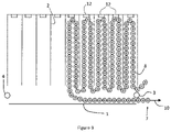
figure 8 représente deux cartouchières selon l'invention disposées en série. - La
figure 9 représente une forme préférée de l'invention comprenant des aimants au fond des compartiments, la boîte à cartouche étant disposée « à l'envers ». - La
figure 10 représente une autre boîte à cartouche selon l'invention. - La présente invention concerne une boîte à cartouche pour munition en bande à maillons permettant de connecter plusieurs boîtes en série, de façon à pouvoir disposer au mieux de l'espace disponible pour l'alimentation de mitrailleuse ou de canon, principalement pour des applications embarquées.
- A cette fin, la boîte à cartouche de l'invention comprend une entrée 5 et une sortie 6 séparées par un rouleau de renvoi 3, l'entrée 5 étant placée au-dessus de la sortie, du même côté de la boîte. Par « dessus », nous entendons ici le haut de la boîte à cartouche placée dans la position destinée au chargement de la boîte. Nous verrons en effet plus loin que, selon des modes préférés de l'invention, la boîte peut être placée, en utilisation, dans pratiquement n'importe quelle position.
- De façon à faciliter le positionnement de la bande, et son déchargement aisé, la boîte à munition de l'invention comprend une pluralité de compartiments 9 séparés par des cloisons verticales 2.
- La bande 7 est initialement placée en zig-zag dans les compartiments 9, depuis le compartiment proche de l'entrée 5 jusqu'au côté opposé. La bande 7 est ensuite repliée vers la sortie. Cette disposition permet que la bande 7 glisse au-dessus des compartiments 9 remplis, glissant sur les cartouches, ce qui évite que les maillons ne se coincent sur le sommet des parois 2 des compartiments 9 vides.
- Avantageusement, le fond des compartiments 9 comprend un aimant permanent 12 permettant de maintenir la bande en position quel que soit la position de la boîte 1. Ceci permet en particulier d'utiliser la boîte à munition retournée, le dessus de la boîte 1 tel que défini ci-avant étant placé en dessous lors de l'utilisation.
- Toujours dans le cas d'une utilisation « à l'envers » (i.e. entrée/sortie en bas du dispositif) il peut être avantageux de placer des alvéoles 23 sur les parois latérales, sur la face opposée à l'entrée/sortie. Dans ce cas, dans le brin de la bande côté sortie du compartiment en train de se vider peut se déplacer librement vers le sortie (mouvement vertical de translation), la cartouche la plus au fond du compartiment effectue un mouvement de rotation qui n'est pas entravé, tandis que le brin côté alvéoles est retenu par celles-ci. Une telle configuration est représentée à la
figure 10 . - Avantageusement, soit les parois alvéolées 22 peuvent facilement être retournées, soit les alvéoles 23 sont disposées sur des plaques amovibles pouvant aisément être disposées à droite ou à gauche des parois séparant les compartiments 9.
- De préférence la boîte 1 peut être aussi retournée latéralement (droite/gauche par rapport aux figures), la boîte 1 comprenant une entrée et une sortie sur chaque face latérales et un second rouleau de renvoi 4 sur la seconde face latérale.
- De façon à permettre un chargement aisé de la boîte à cartouche, la face supérieure est amovible ou peut être fixée au moyen d'une charnière, ce qui non seulement facilite le chargement de la bande, mais permet aussi de faciliter le changement de face d'entrée/sortie.
- La boîte comprenant une entrée et une sortie sur chaque face, deux (ou plus) boîtes peuvent facilement être connectées en série, ce qui permet d'optimiser l'espace occupé par les munitions, sans qu'il soit besoin de dispositif d'alimentation supplémentaire.
Claims (5)
- Ensemble d'au moins deux boîtes à cartouches chacune des au moins deux Boîtes à cartouches comprenant :- une boîte (1) comprenant une entrée (5) et une sortie (6), la sortie (6) étant placée sous l'entrée (5) et séparée de celle-ci par un rouleau de renvoi (3);- une pluralité de compartiments (9) séparés par des cloisons (2) ;- une bande (7) de cartouches (8), ladite bande de cartouche passant par l'entrée (5), est ensuite repliée dans les compartiments (9), du compartiment (9) le plus proche de l'entrée (5) au compartiment le plus éloigné, la bande passant ensuite par la sortie (6), au-dessus du rouleau de renvoi (3) la bande (7) de cartouche sortant de la première boîte étant connectée à la bande entrant dans la seconde boîte.
- Ensemble d'au moins deux boîtes à cartouches selon la revendication 1, chacune des boîtes à cartouches comprenant un couvercle amovible permettant de facilement inverser le côté de sortie de la bande.
- Ensemble d'au moins deux boîtes à cartouches selon l'une des revendications précédentes dans lequelle un aimant permanent (12) est disposé au fond de chaque compartiment (9), chaque aimant (12) permettant de maintenir la bande (7) de cartouches dans le compartiment (9) quel que soit la position de la boîte.
- Ensemble d'au moins deux boîtes à cartouches selon l'une des revendications précédentes comprenant une seconde entrée et une seconde sortie séparées par un second rouleau de renvoi (4) sur la face opposée de la boîte de façon à pouvoir indifféremment placer l'entrée et la sortie à gauche ou à droite de la boîte à cartouche.
- Ensemble d'au moins deux boîtes à cartouches selon l'une des revendications 1 à 3 dans laquelle les cloisons 22 des compartiments 9 comprennent sur leur face opposée à l'entrée/sortie des alvéoles 23 permettant de soutenir un brin de bande statique lors du déchargement du compartiment.
Applications Claiming Priority (2)
| Application Number | Priority Date | Filing Date | Title |
|---|---|---|---|
| BE2017/5293A BE1025175B1 (fr) | 2017-04-25 | 2017-04-25 | Boite a cartouche pour bande de munitions |
| PCT/EP2018/060424 WO2018197456A1 (fr) | 2017-04-25 | 2018-04-24 | Boîte a cartouche pour bande de munitions |
Publications (2)
| Publication Number | Publication Date |
|---|---|
| EP3615879A1 EP3615879A1 (fr) | 2020-03-04 |
| EP3615879B1 true EP3615879B1 (fr) | 2022-09-21 |
Family
ID=58692247
Family Applications (1)
| Application Number | Title | Priority Date | Filing Date |
|---|---|---|---|
| EP18719566.4A Active EP3615879B1 (fr) | 2017-04-25 | 2018-04-24 | Ensemble d'au moins deux boîtes a cartouches pour bande de munitions |
Country Status (8)
| Country | Link |
|---|---|
| US (1) | US10907917B2 (fr) |
| EP (1) | EP3615879B1 (fr) |
| KR (1) | KR20200003832A (fr) |
| AU (1) | AU2018259006A1 (fr) |
| BE (1) | BE1025175B1 (fr) |
| CA (1) | CA3061207A1 (fr) |
| SG (1) | SG11201909933RA (fr) |
| WO (1) | WO2018197456A1 (fr) |
Families Citing this family (1)
| Publication number | Priority date | Publication date | Assignee | Title |
|---|---|---|---|---|
| KR102828359B1 (ko) * | 2020-03-02 | 2025-07-01 | 한화에어로스페이스 주식회사 | 탄약 저장 박스 |
Family Cites Families (32)
| Publication number | Priority date | Publication date | Assignee | Title |
|---|---|---|---|---|
| US1790867A (en) * | 1931-02-03 | jervey | ||
| US1901868A (en) * | 1930-09-15 | 1933-03-21 | Dabrasky August | Method and means for supplying cartridge belts to a feed mechanism |
| BE416237A (fr) * | 1935-06-28 | |||
| GB557686A (en) * | 1938-11-09 | 1943-12-01 | Martin James | Improvements in and relating to ammunition boxes and means for delivering cartridges therefrom to machine guns and the like |
| US2398263A (en) * | 1941-03-20 | 1946-04-09 | Curtiss Wright Corp | Multiple ammunition boxes |
| US2388958A (en) * | 1943-04-09 | 1945-11-13 | United Shoe Machinery Corp | Ammunition feed device |
| US2452545A (en) * | 1944-07-28 | 1948-11-02 | Wilson C Broga | Ammunition chest |
| US2470475A (en) * | 1944-09-27 | 1949-05-17 | Bristol Aeroplane Co Ltd | Ammunition box |
| US2573774A (en) * | 1948-02-12 | 1951-11-06 | United Shoe Machinery Corp | Ammunition container |
| US2710561A (en) * | 1950-02-18 | 1955-06-14 | Glenn L Martin Co | Ammunition box |
| GB759060A (en) * | 1954-01-18 | 1956-10-10 | Brevets Aero Mecaniques | Improvements in ammunition magazines for guns |
| US2874615A (en) * | 1955-03-28 | 1959-02-24 | Nobles Engineering Company | Ammunition storage box |
| US2889751A (en) * | 1957-05-21 | 1959-06-09 | Andrew G Bilek | Ammunition magazine |
| CH476972A (de) * | 1967-06-16 | 1969-08-15 | Oerlikon Buehrle Ag | Munitionsbehälter |
| CH577669A5 (fr) * | 1974-04-10 | 1976-07-15 | Oerlikon Buehrle Ag | |
| DE2716892C2 (de) * | 1977-04-16 | 1987-02-26 | Rheinmetall GmbH, 4000 Düsseldorf | Schwimmend gelagerte automatische Rohrwaffe |
| US4393746A (en) * | 1981-07-31 | 1983-07-19 | The United States Of America As Represented By The Secretay Of The Army | Ammunition magazine with built-in compartment covers |
| DE3262666D1 (en) * | 1981-10-14 | 1985-04-25 | Oerlikon Buehrle Ag | Chest for ammunition, especially a drum magazine |
| ATE32144T1 (de) * | 1983-11-04 | 1988-02-15 | Oerlikon Buehrle Ag | Munitionsbehaelter fuer gegurtete munition. |
| US4573395A (en) * | 1983-12-19 | 1986-03-04 | Ares, Inc. | Linkless ammunition magazine with shell buffer |
| US4681019A (en) * | 1984-12-21 | 1987-07-21 | Heckler & Koch Gmbh | Magazine for automatic weapons |
| US4876940A (en) * | 1988-04-14 | 1989-10-31 | General Electric Company | Magazine ammunition conveying system |
| GB8812464D0 (en) * | 1988-05-26 | 1988-08-24 | Lucas Ind Plc | Apparatus & method for supply of belt-linked ammunition |
| US4882972A (en) * | 1988-08-15 | 1989-11-28 | General Electric Company | Dual caliber ammunition handling system |
| US4974490A (en) * | 1989-12-01 | 1990-12-04 | General Electric Company | Multi-bay magazine for belted ammunition |
| DE59102695D1 (de) * | 1990-05-22 | 1994-10-06 | Contraves Ag | Vorrichtung zum Zuführen von Patronen zu einer Feuerwaffe. |
| US5149909A (en) * | 1991-06-13 | 1992-09-22 | North American Dynamics | Opposed round parallel path single bay ammunition feed system |
| AT406199B (de) * | 1997-11-21 | 2000-03-27 | Steyr Daimler Puch Ag | Behälter für gegurtete munition |
| US6389948B1 (en) * | 1999-01-28 | 2002-05-21 | Heckler & Koch Gmbh | Ammunition feed device for beltless fed ammunition |
| US7913610B2 (en) * | 2008-07-18 | 2011-03-29 | Kongsberg Defence & Aerospace | Ammunition retainer for linked ammunition |
| IL204088A0 (en) * | 2010-02-21 | 2010-12-30 | Elbit Systems Ltd | Ammunition magazine and loading device thereof |
| AU2015336154B2 (en) * | 2014-10-21 | 2018-11-08 | Moog Inc. | Ammunition storage system |
-
2017
- 2017-04-25 BE BE2017/5293A patent/BE1025175B1/fr not_active IP Right Cessation
-
2018
- 2018-04-24 AU AU2018259006A patent/AU2018259006A1/en not_active Abandoned
- 2018-04-24 EP EP18719566.4A patent/EP3615879B1/fr active Active
- 2018-04-24 WO PCT/EP2018/060424 patent/WO2018197456A1/fr not_active Ceased
- 2018-04-24 CA CA3061207A patent/CA3061207A1/fr active Pending
- 2018-04-24 US US16/608,746 patent/US10907917B2/en not_active Expired - Fee Related
- 2018-04-24 KR KR1020197033484A patent/KR20200003832A/ko not_active Abandoned
- 2018-04-24 SG SG11201909933R patent/SG11201909933RA/en unknown
Also Published As
| Publication number | Publication date |
|---|---|
| EP3615879A1 (fr) | 2020-03-04 |
| BE1025175A1 (fr) | 2018-11-21 |
| KR20200003832A (ko) | 2020-01-10 |
| SG11201909933RA (en) | 2019-11-28 |
| US20200200497A1 (en) | 2020-06-25 |
| WO2018197456A1 (fr) | 2018-11-01 |
| CA3061207A1 (fr) | 2018-11-01 |
| US10907917B2 (en) | 2021-02-02 |
| BE1025175B1 (fr) | 2018-11-28 |
| AU2018259006A1 (en) | 2019-11-21 |
Similar Documents
| Publication | Publication Date | Title |
|---|---|---|
| US3219244A (en) | Shotgun shell dispenser | |
| US8955697B2 (en) | Firearm magazine storage rack | |
| US20100126053A1 (en) | Ammunition Magazine with Four Ammunition Stacks | |
| EP2724960B1 (fr) | Installation de stockage et de délivrance de boîtes de médicaments | |
| ES2172304T3 (es) | Cargador automatico orientado horizontalmente para cartuchos de almacenamiento de datos. | |
| CA3001432C (fr) | Dispositif d'alimentation en munitions de moyen calibre a plateau tournant | |
| JP2008195458A (ja) | 棒状製品の容器への充填装置及びその方法 | |
| FR3055305B1 (fr) | Entrepot modulable de stockage et de manutention notamment d'armes et navire comportant un tel entrepot | |
| EP3523594B1 (fr) | Dispositif d'éjection de douilles et/ou de maillons issus d'une chaîne ou bande de munitions associée à une arme principale et/ou secondaire | |
| WO2018197456A1 (fr) | Boîte a cartouche pour bande de munitions | |
| EP3523595B1 (fr) | Dispositif de calage pour obus et casier a charges propulsives apte a accueillir un tel dispositif | |
| FR2753784A1 (fr) | Dispositif d'alimentation en munitions d'une arme montee sur aeronef, equipe d'un tel dispositif | |
| EP1715281B1 (fr) | Dispositif d'alimentation d'une arme à partir de plusieurs caisses à munitions | |
| US20070084509A1 (en) | Fuel tank for spacecraft | |
| JP3197840U (ja) | バケットエレベータ装置 | |
| FR2743414A1 (fr) | Magasin de stockage et d'alimentation de modules constituant des charges propulsives pour canon d'artillerie | |
| US1343374A (en) | Ammunition-receptacle | |
| EP3742102B1 (fr) | Dispositif d'ejection de maillons de munitions | |
| EP1041876B1 (fr) | Conditionnement pour le transport en emersion de poissons vivants de l'ordre des pleuronectiformes | |
| US20140339103A1 (en) | Multiple Ammunition Storage System | |
| FR3022226A1 (fr) | Conteneur isotherme pour le stockage et/ou le transport de la glace carbonique | |
| RU2196287C1 (ru) | Система подачи боеприпасов автоматической пушки с магазином-звеньесборником | |
| FR2840979A1 (fr) | Dispositif de stockage et/ou transport d'elements de munition | |
| WO2024256079A1 (fr) | Installation de tri d'objets hétérogènes et son système de déchargement ordonnés d'objets dans des réceptacles de tri | |
| EP4157714A1 (fr) | Dispositif de fixation de packs batterie, dispositif d'alimentation et cloisons associés |
Legal Events
| Date | Code | Title | Description |
|---|---|---|---|
| STAA | Information on the status of an ep patent application or granted ep patent |
Free format text: STATUS: UNKNOWN |
|
| STAA | Information on the status of an ep patent application or granted ep patent |
Free format text: STATUS: THE INTERNATIONAL PUBLICATION HAS BEEN MADE |
|
| PUAI | Public reference made under article 153(3) epc to a published international application that has entered the european phase |
Free format text: ORIGINAL CODE: 0009012 |
|
| STAA | Information on the status of an ep patent application or granted ep patent |
Free format text: STATUS: REQUEST FOR EXAMINATION WAS MADE |
|
| 17P | Request for examination filed |
Effective date: 20191002 |
|
| AK | Designated contracting states |
Kind code of ref document: A1 Designated state(s): AL AT BE BG CH CY CZ DE DK EE ES FI FR GB GR HR HU IE IS IT LI LT LU LV MC MK MT NL NO PL PT RO RS SE SI SK SM TR |
|
| AX | Request for extension of the european patent |
Extension state: BA ME |
|
| DAV | Request for validation of the european patent (deleted) | ||
| DAX | Request for extension of the european patent (deleted) | ||
| STAA | Information on the status of an ep patent application or granted ep patent |
Free format text: STATUS: EXAMINATION IS IN PROGRESS |
|
| 17Q | First examination report despatched |
Effective date: 20201112 |
|
| RIN1 | Information on inventor provided before grant (corrected) |
Inventor name: JASPART, OLIVIER Inventor name: JADIN, FREDERIC Inventor name: BAILLY, YANNICK Inventor name: ROGGEN, PATRICK |
|
| GRAP | Despatch of communication of intention to grant a patent |
Free format text: ORIGINAL CODE: EPIDOSNIGR1 |
|
| STAA | Information on the status of an ep patent application or granted ep patent |
Free format text: STATUS: GRANT OF PATENT IS INTENDED |
|
| INTG | Intention to grant announced |
Effective date: 20220419 |
|
| GRAS | Grant fee paid |
Free format text: ORIGINAL CODE: EPIDOSNIGR3 |
|
| GRAA | (expected) grant |
Free format text: ORIGINAL CODE: 0009210 |
|
| STAA | Information on the status of an ep patent application or granted ep patent |
Free format text: STATUS: THE PATENT HAS BEEN GRANTED |
|
| AK | Designated contracting states |
Kind code of ref document: B1 Designated state(s): AL AT BE BG CH CY CZ DE DK EE ES FI FR GB GR HR HU IE IS IT LI LT LU LV MC MK MT NL NO PL PT RO RS SE SI SK SM TR |
|
| REG | Reference to a national code |
Ref country code: GB Ref legal event code: FG4D Free format text: NOT ENGLISH |
|
| REG | Reference to a national code |
Ref country code: CH Ref legal event code: EP |
|
| REG | Reference to a national code |
Ref country code: IE Ref legal event code: FG4D Free format text: LANGUAGE OF EP DOCUMENT: FRENCH |
|
| REG | Reference to a national code |
Ref country code: DE Ref legal event code: R096 Ref document number: 602018040876 Country of ref document: DE |
|
| REG | Reference to a national code |
Ref country code: AT Ref legal event code: REF Ref document number: 1520145 Country of ref document: AT Kind code of ref document: T Effective date: 20221015 |
|
| REG | Reference to a national code |
Ref country code: LT Ref legal event code: MG9D |
|
| REG | Reference to a national code |
Ref country code: NL Ref legal event code: MP Effective date: 20220921 |
|
| PG25 | Lapsed in a contracting state [announced via postgrant information from national office to epo] |
Ref country code: SE Free format text: LAPSE BECAUSE OF FAILURE TO SUBMIT A TRANSLATION OF THE DESCRIPTION OR TO PAY THE FEE WITHIN THE PRESCRIBED TIME-LIMIT Effective date: 20220921 Ref country code: RS Free format text: LAPSE BECAUSE OF FAILURE TO SUBMIT A TRANSLATION OF THE DESCRIPTION OR TO PAY THE FEE WITHIN THE PRESCRIBED TIME-LIMIT Effective date: 20220921 Ref country code: NO Free format text: LAPSE BECAUSE OF FAILURE TO SUBMIT A TRANSLATION OF THE DESCRIPTION OR TO PAY THE FEE WITHIN THE PRESCRIBED TIME-LIMIT Effective date: 20221221 Ref country code: LV Free format text: LAPSE BECAUSE OF FAILURE TO SUBMIT A TRANSLATION OF THE DESCRIPTION OR TO PAY THE FEE WITHIN THE PRESCRIBED TIME-LIMIT Effective date: 20220921 Ref country code: LT Free format text: LAPSE BECAUSE OF FAILURE TO SUBMIT A TRANSLATION OF THE DESCRIPTION OR TO PAY THE FEE WITHIN THE PRESCRIBED TIME-LIMIT Effective date: 20220921 Ref country code: FI Free format text: LAPSE BECAUSE OF FAILURE TO SUBMIT A TRANSLATION OF THE DESCRIPTION OR TO PAY THE FEE WITHIN THE PRESCRIBED TIME-LIMIT Effective date: 20220921 |
|
| REG | Reference to a national code |
Ref country code: AT Ref legal event code: MK05 Ref document number: 1520145 Country of ref document: AT Kind code of ref document: T Effective date: 20220921 |
|
| PG25 | Lapsed in a contracting state [announced via postgrant information from national office to epo] |
Ref country code: HR Free format text: LAPSE BECAUSE OF FAILURE TO SUBMIT A TRANSLATION OF THE DESCRIPTION OR TO PAY THE FEE WITHIN THE PRESCRIBED TIME-LIMIT Effective date: 20220921 Ref country code: GR Free format text: LAPSE BECAUSE OF FAILURE TO SUBMIT A TRANSLATION OF THE DESCRIPTION OR TO PAY THE FEE WITHIN THE PRESCRIBED TIME-LIMIT Effective date: 20221222 |
|
| PG25 | Lapsed in a contracting state [announced via postgrant information from national office to epo] |
Ref country code: SM Free format text: LAPSE BECAUSE OF FAILURE TO SUBMIT A TRANSLATION OF THE DESCRIPTION OR TO PAY THE FEE WITHIN THE PRESCRIBED TIME-LIMIT Effective date: 20220921 Ref country code: RO Free format text: LAPSE BECAUSE OF FAILURE TO SUBMIT A TRANSLATION OF THE DESCRIPTION OR TO PAY THE FEE WITHIN THE PRESCRIBED TIME-LIMIT Effective date: 20220921 Ref country code: PT Free format text: LAPSE BECAUSE OF FAILURE TO SUBMIT A TRANSLATION OF THE DESCRIPTION OR TO PAY THE FEE WITHIN THE PRESCRIBED TIME-LIMIT Effective date: 20230123 Ref country code: ES Free format text: LAPSE BECAUSE OF FAILURE TO SUBMIT A TRANSLATION OF THE DESCRIPTION OR TO PAY THE FEE WITHIN THE PRESCRIBED TIME-LIMIT Effective date: 20220921 Ref country code: CZ Free format text: LAPSE BECAUSE OF FAILURE TO SUBMIT A TRANSLATION OF THE DESCRIPTION OR TO PAY THE FEE WITHIN THE PRESCRIBED TIME-LIMIT Effective date: 20220921 Ref country code: AT Free format text: LAPSE BECAUSE OF FAILURE TO SUBMIT A TRANSLATION OF THE DESCRIPTION OR TO PAY THE FEE WITHIN THE PRESCRIBED TIME-LIMIT Effective date: 20220921 |
|
| PG25 | Lapsed in a contracting state [announced via postgrant information from national office to epo] |
Ref country code: SK Free format text: LAPSE BECAUSE OF FAILURE TO SUBMIT A TRANSLATION OF THE DESCRIPTION OR TO PAY THE FEE WITHIN THE PRESCRIBED TIME-LIMIT Effective date: 20220921 Ref country code: PL Free format text: LAPSE BECAUSE OF FAILURE TO SUBMIT A TRANSLATION OF THE DESCRIPTION OR TO PAY THE FEE WITHIN THE PRESCRIBED TIME-LIMIT Effective date: 20220921 Ref country code: IS Free format text: LAPSE BECAUSE OF FAILURE TO SUBMIT A TRANSLATION OF THE DESCRIPTION OR TO PAY THE FEE WITHIN THE PRESCRIBED TIME-LIMIT Effective date: 20230121 Ref country code: EE Free format text: LAPSE BECAUSE OF FAILURE TO SUBMIT A TRANSLATION OF THE DESCRIPTION OR TO PAY THE FEE WITHIN THE PRESCRIBED TIME-LIMIT Effective date: 20220921 |
|
| REG | Reference to a national code |
Ref country code: DE Ref legal event code: R097 Ref document number: 602018040876 Country of ref document: DE |
|
| PG25 | Lapsed in a contracting state [announced via postgrant information from national office to epo] |
Ref country code: NL Free format text: LAPSE BECAUSE OF FAILURE TO SUBMIT A TRANSLATION OF THE DESCRIPTION OR TO PAY THE FEE WITHIN THE PRESCRIBED TIME-LIMIT Effective date: 20220921 Ref country code: AL Free format text: LAPSE BECAUSE OF FAILURE TO SUBMIT A TRANSLATION OF THE DESCRIPTION OR TO PAY THE FEE WITHIN THE PRESCRIBED TIME-LIMIT Effective date: 20220921 |
|
| PLBE | No opposition filed within time limit |
Free format text: ORIGINAL CODE: 0009261 |
|
| STAA | Information on the status of an ep patent application or granted ep patent |
Free format text: STATUS: NO OPPOSITION FILED WITHIN TIME LIMIT |
|
| PG25 | Lapsed in a contracting state [announced via postgrant information from national office to epo] |
Ref country code: DK Free format text: LAPSE BECAUSE OF FAILURE TO SUBMIT A TRANSLATION OF THE DESCRIPTION OR TO PAY THE FEE WITHIN THE PRESCRIBED TIME-LIMIT Effective date: 20220921 |
|
| 26N | No opposition filed |
Effective date: 20230622 |
|
| PG25 | Lapsed in a contracting state [announced via postgrant information from national office to epo] |
Ref country code: SI Free format text: LAPSE BECAUSE OF FAILURE TO SUBMIT A TRANSLATION OF THE DESCRIPTION OR TO PAY THE FEE WITHIN THE PRESCRIBED TIME-LIMIT Effective date: 20220921 |
|
| REG | Reference to a national code |
Ref country code: DE Ref legal event code: R119 Ref document number: 602018040876 Country of ref document: DE |
|
| REG | Reference to a national code |
Ref country code: CH Ref legal event code: PL |
|
| GBPC | Gb: european patent ceased through non-payment of renewal fee |
Effective date: 20230424 |
|
| PG25 | Lapsed in a contracting state [announced via postgrant information from national office to epo] |
Ref country code: LU Free format text: LAPSE BECAUSE OF NON-PAYMENT OF DUE FEES Effective date: 20230424 |
|
| REG | Reference to a national code |
Ref country code: BE Ref legal event code: MM Effective date: 20230430 |
|
| PG25 | Lapsed in a contracting state [announced via postgrant information from national office to epo] |
Ref country code: MC Free format text: LAPSE BECAUSE OF FAILURE TO SUBMIT A TRANSLATION OF THE DESCRIPTION OR TO PAY THE FEE WITHIN THE PRESCRIBED TIME-LIMIT Effective date: 20220921 |
|
| PG25 | Lapsed in a contracting state [announced via postgrant information from national office to epo] |
Ref country code: GB Free format text: LAPSE BECAUSE OF NON-PAYMENT OF DUE FEES Effective date: 20230424 |
|
| PG25 | Lapsed in a contracting state [announced via postgrant information from national office to epo] |
Ref country code: MC Free format text: LAPSE BECAUSE OF FAILURE TO SUBMIT A TRANSLATION OF THE DESCRIPTION OR TO PAY THE FEE WITHIN THE PRESCRIBED TIME-LIMIT Effective date: 20220921 Ref country code: LI Free format text: LAPSE BECAUSE OF NON-PAYMENT OF DUE FEES Effective date: 20230430 Ref country code: GB Free format text: LAPSE BECAUSE OF NON-PAYMENT OF DUE FEES Effective date: 20230424 Ref country code: FR Free format text: LAPSE BECAUSE OF NON-PAYMENT OF DUE FEES Effective date: 20230430 Ref country code: DE Free format text: LAPSE BECAUSE OF NON-PAYMENT OF DUE FEES Effective date: 20231103 Ref country code: CH Free format text: LAPSE BECAUSE OF NON-PAYMENT OF DUE FEES Effective date: 20230430 |
|
| REG | Reference to a national code |
Ref country code: IE Ref legal event code: MM4A |
|
| PG25 | Lapsed in a contracting state [announced via postgrant information from national office to epo] |
Ref country code: BE Free format text: LAPSE BECAUSE OF NON-PAYMENT OF DUE FEES Effective date: 20230430 |
|
| PG25 | Lapsed in a contracting state [announced via postgrant information from national office to epo] |
Ref country code: IE Free format text: LAPSE BECAUSE OF NON-PAYMENT OF DUE FEES Effective date: 20230424 |
|
| PG25 | Lapsed in a contracting state [announced via postgrant information from national office to epo] |
Ref country code: IE Free format text: LAPSE BECAUSE OF NON-PAYMENT OF DUE FEES Effective date: 20230424 |
|
| PG25 | Lapsed in a contracting state [announced via postgrant information from national office to epo] |
Ref country code: IT Free format text: LAPSE BECAUSE OF FAILURE TO SUBMIT A TRANSLATION OF THE DESCRIPTION OR TO PAY THE FEE WITHIN THE PRESCRIBED TIME-LIMIT Effective date: 20220921 |
|
| PG25 | Lapsed in a contracting state [announced via postgrant information from national office to epo] |
Ref country code: BG Free format text: LAPSE BECAUSE OF FAILURE TO SUBMIT A TRANSLATION OF THE DESCRIPTION OR TO PAY THE FEE WITHIN THE PRESCRIBED TIME-LIMIT Effective date: 20220921 |
|
| PG25 | Lapsed in a contracting state [announced via postgrant information from national office to epo] |
Ref country code: BG Free format text: LAPSE BECAUSE OF FAILURE TO SUBMIT A TRANSLATION OF THE DESCRIPTION OR TO PAY THE FEE WITHIN THE PRESCRIBED TIME-LIMIT Effective date: 20220921 |
|
| PG25 | Lapsed in a contracting state [announced via postgrant information from national office to epo] |
Ref country code: CY Free format text: LAPSE BECAUSE OF FAILURE TO SUBMIT A TRANSLATION OF THE DESCRIPTION OR TO PAY THE FEE WITHIN THE PRESCRIBED TIME-LIMIT; INVALID AB INITIO Effective date: 20180424 |
|
| PG25 | Lapsed in a contracting state [announced via postgrant information from national office to epo] |
Ref country code: HU Free format text: LAPSE BECAUSE OF FAILURE TO SUBMIT A TRANSLATION OF THE DESCRIPTION OR TO PAY THE FEE WITHIN THE PRESCRIBED TIME-LIMIT; INVALID AB INITIO Effective date: 20180424 |
|
| PG25 | Lapsed in a contracting state [announced via postgrant information from national office to epo] |
Ref country code: TR Free format text: LAPSE BECAUSE OF FAILURE TO SUBMIT A TRANSLATION OF THE DESCRIPTION OR TO PAY THE FEE WITHIN THE PRESCRIBED TIME-LIMIT Effective date: 20220921 |
|
| PG25 | Lapsed in a contracting state [announced via postgrant information from national office to epo] |
Ref country code: MT Free format text: LAPSE BECAUSE OF NON-PAYMENT OF DUE FEES Effective date: 20230424 |