EP3615823B1 - Cardan joint - Google Patents
Cardan joint Download PDFInfo
- Publication number
- EP3615823B1 EP3615823B1 EP18721314.5A EP18721314A EP3615823B1 EP 3615823 B1 EP3615823 B1 EP 3615823B1 EP 18721314 A EP18721314 A EP 18721314A EP 3615823 B1 EP3615823 B1 EP 3615823B1
- Authority
- EP
- European Patent Office
- Prior art keywords
- yoke
- linkage
- shaft
- axis
- backlash
- Prior art date
- Legal status (The legal status is an assumption and is not a legal conclusion. Google has not performed a legal analysis and makes no representation as to the accuracy of the status listed.)
- Active
Links
Images


Classifications
-
- F—MECHANICAL ENGINEERING; LIGHTING; HEATING; WEAPONS; BLASTING
- F16—ENGINEERING ELEMENTS AND UNITS; GENERAL MEASURES FOR PRODUCING AND MAINTAINING EFFECTIVE FUNCTIONING OF MACHINES OR INSTALLATIONS; THERMAL INSULATION IN GENERAL
- F16D—COUPLINGS FOR TRANSMITTING ROTATION; CLUTCHES; BRAKES
- F16D3/00—Yielding couplings, i.e. with means permitting movement between the connected parts during the drive
- F16D3/16—Universal joints in which flexibility is produced by means of pivots or sliding or rolling connecting parts
- F16D3/26—Hooke's joints or other joints with an equivalent intermediate member to which each coupling part is pivotally or slidably connected
- F16D3/38—Hooke's joints or other joints with an equivalent intermediate member to which each coupling part is pivotally or slidably connected with a single intermediate member with trunnions or bearings arranged on two axes perpendicular to one another
Definitions
- the present invention relates to a cardan joint with an adjustable backlash mechanism.
- Cardan joints also referred to as universal joints
- Cardan joints are commonly used in mechanical systems in order to transfer rotary motion from one part to another when said parts are not necessarily parallel.
- a cardan joint comprises a pair of yokes connected by a linkage (also referred to as a spider or cross-shaft).
- the connection between any given yoke and the linkage may be subject to backlash.
- Backlash is generally understood to mean the maximum distance or angle through which any part of a mechanical system may be moved in one direction without applying appreciable force or motion to the next part in mechanical sequence.
- backlash can refer to unnecessary, or unwanted, movement of either the yoke or linkage which does not aid in the transfer of rotational force.
- US Patent Number 5,062,730 describes a cardan joint having two yokes coupled by a coupling link.
- the joint as disclosed in this patent is manufactured with a high degree of accuracy in an attempt to mitigate the effects of backlash.
- the degree to which backlash is present is highly dependent on the manufacturing quality, and moreover any backlash introduced by use of the joint cannot be corrected.
- US Patent Number 6,926,611 describes a cardan joint with elastomeric bearings.
- the bearings are preloaded in compression, and comprise laminated segments with reduced resistance to shear deformation or rubber cords providing reduced torsional stiffness.
- this joint has a large number of components, which renders it complex and may increase the unit price substantially. Furthermore any backlash within the joint cannot be corrected after manufacture or assembly
- Multi-axis positioners are often used in multi-axis machining and other related roles.
- a multi-axis positioner should accurately move a workpiece of a sample, and many examples do so through the use of cardan joints connected to extensible rods.
- the movement of the positioner needs to be highly accurate (in some examples to within microns) and therefore any backlash within the cardan joints can negatively affect the overall accuracy of the positioner.
- Conventional cardan joints cannot be tightened or have their stiffness and/or backlash adjusted.
- the invention provides a cardan joint according to claim 1.
- the degree of backlash may be preloaded for the joint and moreover can be adjusted without requiring dismantling of the joint and so can be performd after the joint has been incorporated in a larger device (such as a multi-axis positioner).
- the ability to adjust the backlash can allow the amount of backlash to be maintained at an effectively constant level over the life of the joint, even if there is wear on the components of the joint which would normally lead to increased backlash.
- the invention provides a multi-axis positioner including a cardan joint as set out according to the first aspect.
- the multi-axis positioner may include several such cardan joints, which may be interconnected, for example by extensible rods.
- the rigidity of the joint which is dependent in part on the degree of backlash, as used in the multi-axis positioner may be adjusted.
- the amount of backlash in the cardan joint(s) in the positioner can be controlled or adjusted, more accurate operation of the positioner may be possible.
- the amount of backlash in the cardan joint(s) may be adjusted to a predetermined level and account taken of this in the control of the positioner.
- the backlash may be adjusted to a level where its contribution to the overall error in the position of the positioner is below a desired level.
- the first yoke or the second yoke may be configured to rotate about an axis of rotation of the linkage, and the backlash adjusting mechanism may be configured to reduce or increase the amount of backlash in an axis transversal to the axis of rotation.
- this can reduce the slackness in the joint (i.e. increase the tightness) by decreasing any gaps between the first or the second yoke and the linkage.
- the backlash adjusting mechanism may be configured to reduce or increase an amount of backlash between the linkage and the first yoke, and the joint may further include: a second backlash adjusting mechanism, the second backlash adjusting mechanism configured to reduce or increase a degree of backlash between the linkage and the second yoke. Conveniently, this can further increase the tightness of the joint and/or provide for control of the backlash in multiple directions.
- At least one backlash adjusting mechanism is provided as one or more slots within the linkage, wherein a width of the or each slot is adjustable.
- the slots may be easily machined within the linkage and provide an accurate adjustment mechanism for backlash.
- the shaft may be a first shaft, the first shaft being fixed to the first yoke or the second yoke and rotatable relative to the linkage.
- the first shaft may be disposed within a housing of the linkage, wherein adjusting the width of the slot adjusts a dimension of the housing.
- the first shaft may be threaded, and may threadedly engage with the linkage to prevent axial displacement of the first shaft relative to the linkage.
- a further backlash adjusting mechanism may be provided as one or more slot(s) within the first yoke and/or the second yoke, wherein a width of the slot(s) are adjustable.
- the joint may include a second shaft, the second shaft being fixed to the linkage and rotatable relative to the first yoke or the second yoke.
- the second shaft may be disposed within a housing of the first yoke or the second yoke, and adjusting the width of the slot may adjust a dimension of the housing.
- the second shaft may be threaded, and may threadedly engage with the first yoke or the second yoke to prevent axial displacement.
- the threaded engagement can serve to further tighten the joint and improve accuracy.
- the or each backlash mechanism may comprise one or more adjustment screws disposed within a threaded bore of either the linkage or the first yoke or the second yoke.
- adjustment screws may provide a simple way of controlling the backlash. Conveniently, the adjustment screws can be operated with the joint assembled.
- the first or second shaft may be fixed to the yoke(s) or the linkage by nuts or by gluing or welding. By fixing the shafts in this way, backlash within the joint in other directions can also be reduced or eliminated.
- the shaft(s) and/or housings are formed of a material with a low-coefficient of friction.
- the first yoke may rotate relative to the linkage around a first axis
- the second yoke may rotate relative to the linkage around a second axis
- the first axis and the second axis may intersect.
- the linkage may comprise a cuboidal shaded housing, the housing having four apertures, each on a respective face of the housing; wherein the four shafts are respectively disposed in each of the four apertures, and each shaft is fixed to the housing.
- such a joint may have reduced dimensions as the linkage can be made smaller.
- the first yoke may rotate relative to the linkage around a first axis
- the second yoke may rotate relative to the linkage around a second axis
- the first axis and second axis may not intersect.
- the linkage may comprise a rectangular shaped housing, the housing have two bores, each on a respective face of the housing; wherein two shafts are respectively disposed within the bores of the linkage, and each shaft is fixed to either the first yoke or second yoke.
- the degree by which the yokes may rotate can be increased.
- Figure 1 shows an exploded view (in perspective) of a cardan joint 100 with improved backlash control according to an embodiment of the present invention.
- the joint comprises a first coupling unit 103, a second coupling unit 123 and a linkage 111 that connects the first and second coupling units.
- the first coupling unit 103 has a base portion 102 and yoke portion (or yoke) 105.
- the base portion 102 is suitable for connecting to a rotary shaft or other mechanical linkage via an aperture 104.
- the yoke 105 includes first and second apertures 106 and 107, through which a shaft 108 passes.
- the shaft may be fixed in place by, for example, nut 109 and nut 110.
- the shaft may be glued or welded to the yoke.
- apertures 106 and 107 may be threaded and the shaft may include corresponding threaded portions; in such examples, the shaft may be threadedly engaged with the apertures thereby fixing it in place. Therefore the shaft 108 is not rotatable relative to the yoke 105.
- a mid-portion of the shaft 108 is disposed within an aperture 113 of a linkage 111.
- the aperture 113 extends through a first face 112 of the linkage 111.
- a slot 118 Connected to the aperture 113 is a slot 118, the width of which may be controlled by adjustment screws 119, the adjustment screws engaging the linkage either side of the slot. Therefore the degree to which there is backlash between the shaft 108 and the linkage 111 can be controlled by the adjustment screws 119 which control a dimension (e.g. a width) of slot 118, which in turn adjusts a dimension (e.g. a radius) of aperture 113.
- Linkage 111 is rotatable around an axis 116 which passes through the yoke 105 and its apertures 106 and 107.
- Backlash may exist in the joint along an axis which is transversal to the axis of rotation 116.
- the gap between the shaft 108 and the aperture 113 may vary along the length of the shaft. Therefore the shaft 108 might be rotatable in an axis transversal to the axis of rotation 116, which can be described as backlash in the joint.
- the linkage 111 is preferably formed of a material with a low-coefficient of friction, as are the shafts 108 and 120.
- the second coupling unit 123 is substantially identical to the first, and also comprises a base portion 124 and yoke portion (or yoke) 126.
- the base portion 124 is suitable for connecting to a rotary shaft or other mechanical linkage via an aperture 125.
- the yoke 126 includes first and second apertures 128 and 127, through which a second shaft 120 passes.
- the second shaft may be fixed in place by, for example, nuts 129 and 130.
- a mid-point of the shaft 120 is disposed within a second aperture 115 of the linkage 111.
- the aperture 115 being disposed on a different face to aperture 113.
- Aperture 115 also includes adjustment slot 121, which is controlled by adjustment screws 122. Therefore the degree of backlash between aperture 115 and the shaft 120 may be adjusted, by adjusting the width slot 121 through adjustment screws 122.
- the linkage 111 is rotatable relative to the yoke 126 about an axis 117.
- first coupling unit such as the apertures and shaft having threaded portions, are equally applicable to the second coupling unit.
- axis of rotation 117 and axis of rotation 116 are offset relative to one another, i.e. they do not intersect. In a variant example of the joint shown in Figure 1 , the axes of rotation do intersect.
- the dimensions of the linkage 111 and yokes 105 and 123 are chosen such that they may rotate by more than ⁇ 50°.
- Figure 2 shows the joint 100 in an assembled form.
- the first and second shafts 120 and 108 are fixed within respective yokes 126 and 105, by nuts. This fixing can also prevent axial displacement of the shaft.
- the linkage 111 is therefore rotatable around axes 116 and 117 and the degree of backlash between the shafts 120 and 108 and the linkage 111 is adjustable via screws 119 and 122.
- Figure 3 shows an example where the linkage 111 has been rotated around axis 116 such that linkage 111, second coupling unit 123, and axis of rotation 117 has been rotated relative to the arrangement shown in Figure 2 .
- the adjustment mechanism i.e. slots 118 and 121 are installed within the linkage 111 present between the two yokes.
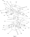
- Figure 4 shows an exploded (in perspective) view of a cardan joint 400 with improved backlash control.
- the adjustment mechanisms are mounted within the yokes of the coupling units rather than in the linkage.
- the joint 400 comprises a first coupling unit 403 which comprises a base 402 and yoke 405.
- the base 402 includes an aperture 404 suitable for attachment to a rotating shaft or other mechanical linkage.
- the yoke 405 includes first and second apertures 406 and 407.
- the coupling unit 403 is identical to the coupling units shown in Figures 1 - 3 .
- the apertures of coupling unit 403 each include respective slots 408. A width of the slots may be adjusted by adjustment screws 409.
- a pair of shafts 410 and 412 are disposed within respective apertures 406 and 407 of the yoke 405. Therefore, by adjustment of the screws 409, the degree of backlash present between the apertures of the yoke and the shafts can be adjusted.
- a second coupling unit 424 comprises a base 425 and yoke 423.
- the second coupling unit 424 is substantially identical to the first coupling unit 403.
- the base 425 includes an aperture 426 suitable for attachment to a rotating shaft or other mechanical linkage.
- the yoke 423 includes first and second apertures 422 and 421.
- the apertures of coupling unit 424 include respective slots 428.
- a width of the slots 428 may be adjusted by adjustment screws 430.
- a pair of shafts 419 and 420 are disposed within respective apertures 422 and 421 of the yoke 423. Therefore, by adjustment of the screws 430, the degree of backlash present between the apertures of the yoke and the shafts can be adjusted.
- the length of the shafts is such that the shafts extend beyond respective apertures 422 and 421 into corresponding apertures 415 of the linkage 413.
- the apertures of the linkage may contain a thread, and the shafts may have a corresponding thread such that they threadedly engage to fix the shafts in place relative to the linkage 413. Therefore the shafts may not rotate relative to the linkage 413, but instead rotate relative to the yoke 423.
- the adjustment mechanism in the example 400 is disposed within respective yokes 405 and 423.
- the shafts shown in the Figures are treated by the application of, for example, a helix tread or similar to thereby increase the surface area and as a result increase the stiffness and static load of the joint.
- untreated shafts may also be used.
- the slots as discussed above may include an elastic element disposed therein, such that theslots are biased to a rest position.
Description
- The present invention relates to a cardan joint with an adjustable backlash mechanism.
- Cardan joints (also referred to as universal joints) are commonly used in mechanical systems in order to transfer rotary motion from one part to another when said parts are not necessarily parallel.
- Generally, a cardan joint comprises a pair of yokes connected by a linkage (also referred to as a spider or cross-shaft). The connection between any given yoke and the linkage may be subject to backlash. Backlash is generally understood to mean the maximum distance or angle through which any part of a mechanical system may be moved in one direction without applying appreciable force or motion to the next part in mechanical sequence. In the context of universal joints, backlash can refer to unnecessary, or unwanted, movement of either the yoke or linkage which does not aid in the transfer of rotational force.
-
US Patent Number 5,062,730 describes a cardan joint having two yokes coupled by a coupling link. The joint as disclosed in this patent is manufactured with a high degree of accuracy in an attempt to mitigate the effects of backlash. However, the degree to which backlash is present is highly dependent on the manufacturing quality, and moreover any backlash introduced by use of the joint cannot be corrected. -
US Patent Number 6,926,611 describes a cardan joint with elastomeric bearings. The bearings are preloaded in compression, and comprise laminated segments with reduced resistance to shear deformation or rubber cords providing reduced torsional stiffness. However this joint has a large number of components, which renders it complex and may increase the unit price substantially. Furthermore any backlash within the joint cannot be corrected after manufacture or assembly - Documents
US 1 583 184 A ,US 1 424 299 A andUS 2002/061782 A1 provide further examples of cardan joints. - Multi-axis positioners are often used in multi-axis machining and other related roles. A multi-axis positioner should accurately move a workpiece of a sample, and many examples do so through the use of cardan joints connected to extensible rods. The movement of the positioner needs to be highly accurate (in some examples to within microns) and therefore any backlash within the cardan joints can negatively affect the overall accuracy of the positioner. Conventional cardan joints cannot be tightened or have their stiffness and/or backlash adjusted.
- Accordingly, there is a need for a cardan joint overcoming the problems listed above.
- Accordingly, in a first aspect, the invention provides a cardan joint according to claim 1.
- Advantageously, the degree of backlash may be preloaded for the joint and moreover can be adjusted without requiring dismantling of the joint and so can be performd after the joint has been incorporated in a larger device (such as a multi-axis positioner). The ability to adjust the backlash can allow the amount of backlash to be maintained at an effectively constant level over the life of the joint, even if there is wear on the components of the joint which would normally lead to increased backlash.
- In a second aspect, the invention provides a multi-axis positioner including a cardan joint as set out according to the first aspect. The multi-axis positioner may include several such cardan joints, which may be interconnected, for example by extensible rods.
- Conveniently, the rigidity of the joint, which is dependent in part on the degree of backlash, as used in the multi-axis positioner may be adjusted.
- As the amount of backlash in the cardan joint(s) in the positioner can be controlled or adjusted, more accurate operation of the positioner may be possible. For example, the amount of backlash in the cardan joint(s) may be adjusted to a predetermined level and account taken of this in the control of the positioner. Alternatively or additionally the backlash may be adjusted to a level where its contribution to the overall error in the position of the positioner is below a desired level.
- Optional features of the invention will now be set out. These are applicable singly or in any combination with any aspect of the invention.
- The first yoke or the second yoke may be configured to rotate about an axis of rotation of the linkage, and the backlash adjusting mechanism may be configured to reduce or increase the amount of backlash in an axis transversal to the axis of rotation.
- Advantageously, this can reduce the slackness in the joint (i.e. increase the tightness) by decreasing any gaps between the first or the second yoke and the linkage.
- The backlash adjusting mechanism may be configured to reduce or increase an amount of backlash between the linkage and the first yoke, and the joint may further include: a second backlash adjusting mechanism, the second backlash adjusting mechanism configured to reduce or increase a degree of backlash between the linkage and the second yoke. Conveniently, this can further increase the tightness of the joint and/or provide for control of the backlash in multiple directions.
- According to the invention, at least one backlash adjusting mechanism is provided as one or more slots within the linkage, wherein a width of the or each slot is adjustable.
- Advantageously, the slots may be easily machined within the linkage and provide an accurate adjustment mechanism for backlash.
- The shaft may be a first shaft, the first shaft being fixed to the first yoke or the second yoke and rotatable relative to the linkage. The first shaft may be disposed within a housing of the linkage, wherein adjusting the width of the slot adjusts a dimension of the housing. The first shaft may be threaded, and may threadedly engage with the linkage to prevent axial displacement of the first shaft relative to the linkage.
- A further backlash adjusting mechanism may be provided as one or more slot(s) within the first yoke and/or the second yoke, wherein a width of the slot(s) are adjustable. The joint may include a second shaft, the second shaft being fixed to the linkage and rotatable relative to the first yoke or the second yoke. The second shaft may be disposed within a housing of the first yoke or the second yoke, and adjusting the width of the slot may adjust a dimension of the housing. The second shaft may be threaded, and may threadedly engage with the first yoke or the second yoke to prevent axial displacement.
- Advantageously, the threaded engagement can serve to further tighten the joint and improve accuracy.
- The or each backlash mechanism may comprise one or more adjustment screws disposed within a threaded bore of either the linkage or the first yoke or the second yoke.
- The use of adjustment screws may provide a simple way of controlling the backlash. Conveniently, the adjustment screws can be operated with the joint assembled.
- The first or second shaft may be fixed to the yoke(s) or the linkage by nuts or by gluing or welding. By fixing the shafts in this way, backlash within the joint in other directions can also be reduced or eliminated.
- Preferably the shaft(s) and/or housings are formed of a material with a low-coefficient of friction.
- The first yoke may rotate relative to the linkage around a first axis, the second yoke may rotate relative to the linkage around a second axis; and the first axis and the second axis may intersect. The linkage may comprise a cuboidal shaded housing, the housing having four apertures, each on a respective face of the housing; wherein the four shafts are respectively disposed in each of the four apertures, and each shaft is fixed to the housing.
- Advantageously, such a joint may have reduced dimensions as the linkage can be made smaller.
- The first yoke may rotate relative to the linkage around a first axis, the second yoke may rotate relative to the linkage around a second axis; and the first axis and second axis may not intersect. The linkage may comprise a rectangular shaped housing, the housing have two bores, each on a respective face of the housing; wherein two shafts are respectively disposed within the bores of the linkage, and each shaft is fixed to either the first yoke or second yoke.
- Advantageously, by spacing the first and second axes of rotation, the degree by which the yokes may rotate can be increased.
- Embodiments of the invention will now be described by way of example with reference to the accompanying drawings in which:
-
Figure 1 shows an exploded perspective view of a cardan joint according to an embodiment of the present invention; -
Figure 2 shows an assembled perspective view of the cardan joint ofFigure 1 in a first position; -
Figure 3 shows an assembled perspective view of the cardan joint ofFigure 1 in a second position; -
Figure 4 shows an exploded perspective view of a cardan joint comprising backlash adjusting mechanisms provided as slots in the yokes; -
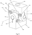
Figure 5 shows an assembled perspective view of the cardan joint ofFigure 4 . -
Figure 1 shows an exploded view (in perspective) of a cardan joint 100 with improved backlash control according to an embodiment of the present invention. The joint comprises afirst coupling unit 103, asecond coupling unit 123 and alinkage 111 that connects the first and second coupling units. - The
first coupling unit 103 has abase portion 102 and yoke portion (or yoke) 105. Thebase portion 102 is suitable for connecting to a rotary shaft or other mechanical linkage via anaperture 104. Theyoke 105 includes first andsecond apertures shaft 108 passes. The shaft may be fixed in place by, for example,nut 109 andnut 110. Alternatively the shaft may be glued or welded to the yoke. As a further alternative,apertures shaft 108 is not rotatable relative to theyoke 105. - A mid-portion of the
shaft 108 is disposed within anaperture 113 of alinkage 111. Theaperture 113 extends through afirst face 112 of thelinkage 111. Connected to theaperture 113 is aslot 118, the width of which may be controlled byadjustment screws 119, the adjustment screws engaging the linkage either side of the slot. Therefore the degree to which there is backlash between theshaft 108 and thelinkage 111 can be controlled by the adjustment screws 119 which control a dimension (e.g. a width) ofslot 118, which in turn adjusts a dimension (e.g. a radius) ofaperture 113.Linkage 111 is rotatable around anaxis 116 which passes through theyoke 105 and itsapertures rotation 116. For example, the gap between theshaft 108 and theaperture 113 may vary along the length of the shaft. Therefore theshaft 108 might be rotatable in an axis transversal to the axis ofrotation 116, which can be described as backlash in the joint. Thelinkage 111 is preferably formed of a material with a low-coefficient of friction, as are theshafts - The
second coupling unit 123 is substantially identical to the first, and also comprises abase portion 124 and yoke portion (or yoke) 126. Thebase portion 124 is suitable for connecting to a rotary shaft or other mechanical linkage via anaperture 125. Theyoke 126 includes first andsecond apertures second shaft 120 passes. The second shaft may be fixed in place by, for example,nuts shaft 120 is disposed within asecond aperture 115 of thelinkage 111. Theaperture 115 being disposed on a different face toaperture 113.Aperture 115 also includesadjustment slot 121, which is controlled by adjustment screws 122. Therefore the degree of backlash betweenaperture 115 and theshaft 120 may be adjusted, by adjusting thewidth slot 121 through adjustment screws 122. Thelinkage 111 is rotatable relative to theyoke 126 about anaxis 117. - Optional features of the first coupling unit, such as the apertures and shaft having threaded portions, are equally applicable to the second coupling unit.
- It can be seen that axis of
rotation 117 and axis ofrotation 116 are offset relative to one another, i.e. they do not intersect. In a variant example of the joint shown inFigure 1 , the axes of rotation do intersect. The dimensions of thelinkage 111 andyokes -
Figure 2 shows the joint 100 in an assembled form. As is clearly shown, the first andsecond shafts respective yokes linkage 111 is therefore rotatable around axes 116 and 117 and the degree of backlash between theshafts linkage 111 is adjustable viascrews Figure 3 shows an example where thelinkage 111 has been rotated aroundaxis 116 such thatlinkage 111,second coupling unit 123, and axis ofrotation 117 has been rotated relative to the arrangement shown inFigure 2 . - In this example, the adjustment mechanism (i.e.
slots 118 and 121) are installed within thelinkage 111 present between the two yokes. -
Figure 4 shows an exploded (in perspective) view of a cardan joint 400 with improved backlash control. In this example, the adjustment mechanisms are mounted within the yokes of the coupling units rather than in the linkage. In detail, the joint 400 comprises afirst coupling unit 403 which comprises abase 402 andyoke 405. Thebase 402 includes anaperture 404 suitable for attachment to a rotating shaft or other mechanical linkage. Theyoke 405 includes first andsecond apertures coupling unit 403 is identical to the coupling units shown inFigures 1 - 3 . However, the apertures ofcoupling unit 403 each includerespective slots 408. A width of the slots may be adjusted by adjustment screws 409. A pair ofshafts respective apertures yoke 405. Therefore, by adjustment of thescrews 409, the degree of backlash present between the apertures of the yoke and the shafts can be adjusted. - The length of the shafts is such that the shafts extend beyond
respective apertures corresponding apertures 414 of alinkage 413. The apertures within the linkage may contain a thread, and the shafts may have a corresponding thread such that they threadedly engage to fix the shafts in place relative to thelinkage 413. Therefore the shafts may not rotate relative to thelinkage 413, but instead rotate relative to theyoke 405. Similarly, asecond coupling unit 424 comprises abase 425 andyoke 423. Thesecond coupling unit 424 is substantially identical to thefirst coupling unit 403. Thebase 425 includes anaperture 426 suitable for attachment to a rotating shaft or other mechanical linkage. Theyoke 423 includes first andsecond apertures coupling unit 424 includerespective slots 428. A width of theslots 428 may be adjusted by adjustment screws 430. A pair ofshafts respective apertures yoke 423. Therefore, by adjustment of thescrews 430, the degree of backlash present between the apertures of the yoke and the shafts can be adjusted. - The length of the shafts is such that the shafts extend beyond
respective apertures corresponding apertures 415 of thelinkage 413. The apertures of the linkage may contain a thread, and the shafts may have a corresponding thread such that they threadedly engage to fix the shafts in place relative to thelinkage 413. Therefore the shafts may not rotate relative to thelinkage 413, but instead rotate relative to theyoke 423. - In contrast to the example shown in
Figures 1 - 3 , the adjustment mechanism in the example 400 is disposed withinrespective yokes - This is clearly shown in
Figure 5 . It should also be noted that, in the example shown inFigure 5 , the first axis ofrotation 417 and second axis ofrotation 418 intersect one another within thelinkage 413. - The shafts shown in the Figures are treated by the application of, for example, a helix tread or similar to thereby increase the surface area and as a result increase the stiffness and static load of the joint. However, untreated shafts may also be used. The slots as discussed above may include an elastic element disposed therein, such that theslots are biased to a rest position.
-
- 100, 400
- Cardan joint
- 102,402,124,424
- Base
- 103, 403, 123, 425
- Coupling unit
- 104, 404, 125, 426
- Aperture within base
- 105,405,126,423
- Yoke
- 106, 107, 406, 407, 127, 128, 421, 422
- Aperture within yoke
- 108,410,412,120,419, 420
- Shaft
- 109, 110, 129, 130
- Nut for fixing shaft to yoke
- 111,413
- Linkage
- 112
- Face of linkage
- 113, 115, 414, 415
- Aperture in linkage
- 116, 117, 417, 418
- Axis of rotation
- 118, 121,408,428
- Slot
- 119, 122, 409, 430
- Adjustment screws
Claims (15)
- A cardan joint (100), comprising:a first yoke (105); anda second yoke (126);wherein the first yoke (105) and the second yoke (126) are connected via a linkage (111);the cardan joint (100) further comprising:a backlash adjusting mechanism, the backlash adjusting mechanism configured to reduce or increase an amount of backlash between the linkage (111) and either the first yoke (105) or the second yoke (126); anda shaft (108, 120), either:fixed to one of the yokes (105, 126) and threadedly engaged to the linkage (111); orfixed to the linkage (111) and threadedly engaged to one of the yokes (105, 126);so as to prevent axial displacement therebetweencharacterised in that the or each backlash adjusting mechanism is provided as one or more slots (118, 121) within the linkage (111), wherein a width of the or each slot (118, 121) is adjustable.
- The cardan joint (100) of claim 1, wherein the first yoke (105) or second yoke (126) is configured to rotate about an axis of rotation of the linkage (111), and wherein the backlash adjusting mechanism is configured to reduce or increase the amount of backlash in an axis transversal to the axis of rotation.
- The cardan joint (100) of claim 1 or claim 2,
wherein the backlash adjusting mechanism is configured to reduce or increase an amount of backlash between the linkage (111) and the first yoke (105), and
the joint (100) further includes:
a second backlash adjusting mechanism, the second backlash adjusting mechanism configured to reduce or increase a degree of backlash between the linkage (111) and the second yoke (126). - The cardan joint (100) of claim 1, wherein the shaft (108, 120) is a first shaft (108), which is fixed to the first yoke (105) or the second yoke (126) and rotatable relative to the linkage (111);
optionally wherein the first shaft (108) is disposed within a housing of the linkage (111), and wherein adjusting the width of the slot (118) adjusts a dimension of the housing. - The cardan joint (100) of claim 4 wherein the first shaft (108) is fixed to the first yoke (105) or the second yoke (126) by nuts or by gluing or welding.
- The cardan joint (100) of any preceding claim, wherein a further backlash adjusting mechanism is provided as one or more slots within the first yoke (105) and/or the second yoke (126), wherein a width of the or each slot is adjustable.
- The cardan joint (100) of claim 6, wherein the shaft is second shaft being fixed to the linkage (111) and rotatable relative to the first yoke (105) or the second yoke (126);
optionally wherein the second shaft is disposed within a housing of the first yoke (105) or the second yoke (126), and wherein adjusting the width of the or each slot adjusts a dimension of the housing;
and optionally wherein the second shaft is fixed to the linkage (111) by gluing or welding. - The cardan joint (100) of any preceding claim, wherein the joint (100) includes a first shaft (108) and a second shaft (120),
the first shaft (108) being:fixed to the first yoke (105) and threadedly engaged to the linkage (111); orfixed to the linkage (111) and threadedly engaged to the first yoke (105);so as to prevent axial displacement therebetween; and
the second shaft (120) being:fixed to the second yoke (126) and threadedly engaged to the linkage (111); orfixed to the linkage (111) and threadedly engaged to the second yoke (126);so as to prevent axial displacement therebetween. - The cardan joint (100) of any preceding claim wherein the shaft(s) (108, 120) and/or housings are formed of a material with a low-coefficient of friction.
- The cardan joint (100) of any preceding claim, wherein the or each backlash adjusting mechanism comprises one or more adjustment screws (119, 122) disposed within a threaded bore.
- The cardan joint (100) of any preceding claim, wherein
the first yoke (105) rotates relative to the linkage (111) around a first axis, the second yoke (126) rotates relative to the linkage (111) around a second axis; and
the first axis and second axis intersect. - The cardan joint (100) of claim 11, wherein the linkage (111) comprises:a cuboidal shaped housing, the housing having four apertures, each on a respective face of the housing;wherein four shafts are respectively disposed in each of the four apertures, and each shaft is fixed to the housing.
- The cardan joint (100) of any of claims 1 - 12, wherein:the linkage (111) rotates relative to the first yoke (105) around a first axis,the linkage (111) rotates relative to the second yoke (126) around a second axis; and
the first axis and second axis do not intersect. - The cardan joint (100) of claim 13, wherein the linkage (111) comprises:a cuboidal shaped housing, the housing have two bores extending therethrough;wherein two shafts are respectively disposed within the bores of the linkage (111), and each shaft (108, 120) is fixed to either the first yoke (105) or second yoke (126).
- A multi-axis positioner including a cardan joint (100) as set out in any of claims 1 - 14.
Applications Claiming Priority (2)
| Application Number | Priority Date | Filing Date | Title |
|---|---|---|---|
| GBGB1706520.2A GB201706520D0 (en) | 2017-04-25 | 2017-04-25 | Cardan joint |
| PCT/EP2018/060387 WO2018197439A1 (en) | 2017-04-25 | 2018-04-23 | Cardan joint |
Publications (3)
| Publication Number | Publication Date |
|---|---|
| EP3615823A1 EP3615823A1 (en) | 2020-03-04 |
| EP3615823B1 true EP3615823B1 (en) | 2021-06-02 |
| EP3615823B8 EP3615823B8 (en) | 2021-07-14 |
Family
ID=58795657
Family Applications (1)
| Application Number | Title | Priority Date | Filing Date |
|---|---|---|---|
| EP18721314.5A Active EP3615823B8 (en) | 2017-04-25 | 2018-04-23 | Cardan joint |
Country Status (3)
| Country | Link |
|---|---|
| EP (1) | EP3615823B8 (en) |
| GB (1) | GB201706520D0 (en) |
| WO (1) | WO2018197439A1 (en) |
Family Cites Families (4)
| Publication number | Priority date | Publication date | Assignee | Title |
|---|---|---|---|---|
| US1424299A (en) * | 1921-03-10 | 1922-08-01 | H S & S Mfg Co | Universal joint |
| US1583184A (en) * | 1925-08-15 | 1926-05-04 | Swan A Sandberg | Universal joint |
| US6454657B1 (en) * | 1998-12-31 | 2002-09-24 | Spicer Driveshaft, Inc. | End yoke for a universal joint assembly |
| WO2001094803A2 (en) * | 2000-06-07 | 2001-12-13 | Ernest Stonier Myburgh | Universal joint |
-
2017
- 2017-04-25 GB GBGB1706520.2A patent/GB201706520D0/en not_active Ceased
-
2018
- 2018-04-23 WO PCT/EP2018/060387 patent/WO2018197439A1/en unknown
- 2018-04-23 EP EP18721314.5A patent/EP3615823B8/en active Active
Also Published As
| Publication number | Publication date |
|---|---|
| GB201706520D0 (en) | 2017-06-07 |
| EP3615823B8 (en) | 2021-07-14 |
| EP3615823A1 (en) | 2020-03-04 |
| WO2018197439A1 (en) | 2018-11-01 |
Similar Documents
| Publication | Publication Date | Title |
|---|---|---|
| JP6289973B2 (en) | Parallel link mechanism and link actuator | |
| US8291782B1 (en) | Actuator assembly for stabilizers | |
| JP6609536B2 (en) | Integrated lens mount | |
| KR102346469B1 (en) | Actuators for Physical Therapy | |
| US20050199085A1 (en) | Link actuating device | |
| KR20070099552A (en) | Variable stiffness flexible joint | |
| US10343709B2 (en) | Restoring torque generating devices | |
| US8033197B2 (en) | Fully floating, self-aligning, self-adjusting gimbal assembly for an active human machine interface | |
| US11407101B2 (en) | Link actuating device | |
| Knabe et al. | Design of a compact, lightweight, electromechanical linear series elastic actuator | |
| JP5535396B2 (en) | Linear actuator | |
| US10988162B2 (en) | Steering column assemblies | |
| CN108463651B (en) | Connecting rod actuating device | |
| EP3615823B1 (en) | Cardan joint | |
| JP6205054B2 (en) | Tool grinder spindle | |
| JPH04233507A (en) | Rotary coupling device | |
| JPH0475403B2 (en) | ||
| WO2015182557A1 (en) | Parallel link mechanism and link operation device | |
| JP2017187159A (en) | Shaft coupling assembly, method for connecting two shafts by shaft coupling assembly, and maintenance method | |
| JP6352054B2 (en) | Parallel link mechanism and link actuator | |
| JP7284978B2 (en) | joint mechanism | |
| JP6774851B2 (en) | Rotation transmission device | |
| JPH03203708A (en) | Focussing system for infinit focus telescope with automatic focusing and temperature compensation | |
| JPS58193931A (en) | Flexible shaft coupling | |
| JP2020143693A (en) | Linear-motion actuator |
Legal Events
| Date | Code | Title | Description |
|---|---|---|---|
| STAA | Information on the status of an ep patent application or granted ep patent |
Free format text: STATUS: UNKNOWN |
|
| STAA | Information on the status of an ep patent application or granted ep patent |
Free format text: STATUS: THE INTERNATIONAL PUBLICATION HAS BEEN MADE |
|
| PUAI | Public reference made under article 153(3) epc to a published international application that has entered the european phase |
Free format text: ORIGINAL CODE: 0009012 |
|
| STAA | Information on the status of an ep patent application or granted ep patent |
Free format text: STATUS: REQUEST FOR EXAMINATION WAS MADE |
|
| 17P | Request for examination filed |
Effective date: 20190930 |
|
| AK | Designated contracting states |
Kind code of ref document: A1 Designated state(s): AL AT BE BG CH CY CZ DE DK EE ES FI FR GB GR HR HU IE IS IT LI LT LU LV MC MK MT NL NO PL PT RO RS SE SI SK SM TR |
|
| AX | Request for extension of the european patent |
Extension state: BA ME |
|
| DAV | Request for validation of the european patent (deleted) | ||
| DAX | Request for extension of the european patent (deleted) | ||
| GRAP | Despatch of communication of intention to grant a patent |
Free format text: ORIGINAL CODE: EPIDOSNIGR1 |
|
| STAA | Information on the status of an ep patent application or granted ep patent |
Free format text: STATUS: GRANT OF PATENT IS INTENDED |
|
| INTG | Intention to grant announced |
Effective date: 20201223 |
|
| GRAS | Grant fee paid |
Free format text: ORIGINAL CODE: EPIDOSNIGR3 |
|
| GRAA | (expected) grant |
Free format text: ORIGINAL CODE: 0009210 |
|
| STAA | Information on the status of an ep patent application or granted ep patent |
Free format text: STATUS: THE PATENT HAS BEEN GRANTED |
|
| REG | Reference to a national code |
Ref country code: CH Ref legal event code: EP |
|
| AK | Designated contracting states |
Kind code of ref document: B1 Designated state(s): AL AT BE BG CH CY CZ DE DK EE ES FI FR GB GR HR HU IE IS IT LI LT LU LV MC MK MT NL NO PL PT RO RS SE SI SK SM TR |
|
| REG | Reference to a national code |
Ref country code: GB Ref legal event code: FG4D |
|
| REG | Reference to a national code |
Ref country code: AT Ref legal event code: REF Ref document number: 1398727 Country of ref document: AT Kind code of ref document: T Effective date: 20210615 |
|
| REG | Reference to a national code |
Ref country code: IE Ref legal event code: FG4D |
|
| REG | Reference to a national code |
Ref country code: DE Ref legal event code: R096 Ref document number: 602018018053 Country of ref document: DE |
|
| REG | Reference to a national code |
Ref country code: CH Ref legal event code: PK Free format text: BERICHTIGUNG B8 |
|
| RAP2 | Party data changed (patent owner data changed or rights of a patent transferred) |
Owner name: FLEX HEX APS Owner name: JOZEF STEFAN INSTITUTE |
|
| REG | Reference to a national code |
Ref country code: LT Ref legal event code: MG9D |
|
| PG25 | Lapsed in a contracting state [announced via postgrant information from national office to epo] |
Ref country code: FI Free format text: LAPSE BECAUSE OF FAILURE TO SUBMIT A TRANSLATION OF THE DESCRIPTION OR TO PAY THE FEE WITHIN THE PRESCRIBED TIME-LIMIT Effective date: 20210602 Ref country code: HR Free format text: LAPSE BECAUSE OF FAILURE TO SUBMIT A TRANSLATION OF THE DESCRIPTION OR TO PAY THE FEE WITHIN THE PRESCRIBED TIME-LIMIT Effective date: 20210602 Ref country code: LT Free format text: LAPSE BECAUSE OF FAILURE TO SUBMIT A TRANSLATION OF THE DESCRIPTION OR TO PAY THE FEE WITHIN THE PRESCRIBED TIME-LIMIT Effective date: 20210602 Ref country code: BG Free format text: LAPSE BECAUSE OF FAILURE TO SUBMIT A TRANSLATION OF THE DESCRIPTION OR TO PAY THE FEE WITHIN THE PRESCRIBED TIME-LIMIT Effective date: 20210902 |
|
| REG | Reference to a national code |
Ref country code: NL Ref legal event code: MP Effective date: 20210602 |
|
| REG | Reference to a national code |
Ref country code: AT Ref legal event code: MK05 Ref document number: 1398727 Country of ref document: AT Kind code of ref document: T Effective date: 20210602 |
|
| PG25 | Lapsed in a contracting state [announced via postgrant information from national office to epo] |
Ref country code: GR Free format text: LAPSE BECAUSE OF FAILURE TO SUBMIT A TRANSLATION OF THE DESCRIPTION OR TO PAY THE FEE WITHIN THE PRESCRIBED TIME-LIMIT Effective date: 20210903 Ref country code: SE Free format text: LAPSE BECAUSE OF FAILURE TO SUBMIT A TRANSLATION OF THE DESCRIPTION OR TO PAY THE FEE WITHIN THE PRESCRIBED TIME-LIMIT Effective date: 20210602 Ref country code: RS Free format text: LAPSE BECAUSE OF FAILURE TO SUBMIT A TRANSLATION OF THE DESCRIPTION OR TO PAY THE FEE WITHIN THE PRESCRIBED TIME-LIMIT Effective date: 20210602 Ref country code: LV Free format text: LAPSE BECAUSE OF FAILURE TO SUBMIT A TRANSLATION OF THE DESCRIPTION OR TO PAY THE FEE WITHIN THE PRESCRIBED TIME-LIMIT Effective date: 20210602 Ref country code: PL Free format text: LAPSE BECAUSE OF FAILURE TO SUBMIT A TRANSLATION OF THE DESCRIPTION OR TO PAY THE FEE WITHIN THE PRESCRIBED TIME-LIMIT Effective date: 20210602 Ref country code: NO Free format text: LAPSE BECAUSE OF FAILURE TO SUBMIT A TRANSLATION OF THE DESCRIPTION OR TO PAY THE FEE WITHIN THE PRESCRIBED TIME-LIMIT Effective date: 20210902 |
|
| PG25 | Lapsed in a contracting state [announced via postgrant information from national office to epo] |
Ref country code: SM Free format text: LAPSE BECAUSE OF FAILURE TO SUBMIT A TRANSLATION OF THE DESCRIPTION OR TO PAY THE FEE WITHIN THE PRESCRIBED TIME-LIMIT Effective date: 20210602 Ref country code: NL Free format text: LAPSE BECAUSE OF FAILURE TO SUBMIT A TRANSLATION OF THE DESCRIPTION OR TO PAY THE FEE WITHIN THE PRESCRIBED TIME-LIMIT Effective date: 20210602 Ref country code: PT Free format text: LAPSE BECAUSE OF FAILURE TO SUBMIT A TRANSLATION OF THE DESCRIPTION OR TO PAY THE FEE WITHIN THE PRESCRIBED TIME-LIMIT Effective date: 20211004 Ref country code: RO Free format text: LAPSE BECAUSE OF FAILURE TO SUBMIT A TRANSLATION OF THE DESCRIPTION OR TO PAY THE FEE WITHIN THE PRESCRIBED TIME-LIMIT Effective date: 20210602 Ref country code: AT Free format text: LAPSE BECAUSE OF FAILURE TO SUBMIT A TRANSLATION OF THE DESCRIPTION OR TO PAY THE FEE WITHIN THE PRESCRIBED TIME-LIMIT Effective date: 20210602 Ref country code: CZ Free format text: LAPSE BECAUSE OF FAILURE TO SUBMIT A TRANSLATION OF THE DESCRIPTION OR TO PAY THE FEE WITHIN THE PRESCRIBED TIME-LIMIT Effective date: 20210602 Ref country code: SK Free format text: LAPSE BECAUSE OF FAILURE TO SUBMIT A TRANSLATION OF THE DESCRIPTION OR TO PAY THE FEE WITHIN THE PRESCRIBED TIME-LIMIT Effective date: 20210602 Ref country code: EE Free format text: LAPSE BECAUSE OF FAILURE TO SUBMIT A TRANSLATION OF THE DESCRIPTION OR TO PAY THE FEE WITHIN THE PRESCRIBED TIME-LIMIT Effective date: 20210602 Ref country code: ES Free format text: LAPSE BECAUSE OF FAILURE TO SUBMIT A TRANSLATION OF THE DESCRIPTION OR TO PAY THE FEE WITHIN THE PRESCRIBED TIME-LIMIT Effective date: 20210602 |
|
| REG | Reference to a national code |
Ref country code: DE Ref legal event code: R097 Ref document number: 602018018053 Country of ref document: DE |
|
| PLBE | No opposition filed within time limit |
Free format text: ORIGINAL CODE: 0009261 |
|
| STAA | Information on the status of an ep patent application or granted ep patent |
Free format text: STATUS: NO OPPOSITION FILED WITHIN TIME LIMIT |
|
| PG25 | Lapsed in a contracting state [announced via postgrant information from national office to epo] |
Ref country code: DK Free format text: LAPSE BECAUSE OF FAILURE TO SUBMIT A TRANSLATION OF THE DESCRIPTION OR TO PAY THE FEE WITHIN THE PRESCRIBED TIME-LIMIT Effective date: 20210602 |
|
| 26N | No opposition filed |
Effective date: 20220303 |
|
| PG25 | Lapsed in a contracting state [announced via postgrant information from national office to epo] |
Ref country code: AL Free format text: LAPSE BECAUSE OF FAILURE TO SUBMIT A TRANSLATION OF THE DESCRIPTION OR TO PAY THE FEE WITHIN THE PRESCRIBED TIME-LIMIT Effective date: 20210602 |
|
| PG25 | Lapsed in a contracting state [announced via postgrant information from national office to epo] |
Ref country code: IT Free format text: LAPSE BECAUSE OF FAILURE TO SUBMIT A TRANSLATION OF THE DESCRIPTION OR TO PAY THE FEE WITHIN THE PRESCRIBED TIME-LIMIT Effective date: 20210602 |
|
| REG | Reference to a national code |
Ref country code: CH Ref legal event code: PL |
|
| REG | Reference to a national code |
Ref country code: BE Ref legal event code: MM Effective date: 20220430 |
|
| PG25 | Lapsed in a contracting state [announced via postgrant information from national office to epo] |
Ref country code: MC Free format text: LAPSE BECAUSE OF FAILURE TO SUBMIT A TRANSLATION OF THE DESCRIPTION OR TO PAY THE FEE WITHIN THE PRESCRIBED TIME-LIMIT Effective date: 20210602 Ref country code: LU Free format text: LAPSE BECAUSE OF NON-PAYMENT OF DUE FEES Effective date: 20220423 Ref country code: LI Free format text: LAPSE BECAUSE OF NON-PAYMENT OF DUE FEES Effective date: 20220430 Ref country code: CH Free format text: LAPSE BECAUSE OF NON-PAYMENT OF DUE FEES Effective date: 20220430 |
|
| PG25 | Lapsed in a contracting state [announced via postgrant information from national office to epo] |
Ref country code: BE Free format text: LAPSE BECAUSE OF NON-PAYMENT OF DUE FEES Effective date: 20220430 |
|
| PG25 | Lapsed in a contracting state [announced via postgrant information from national office to epo] |
Ref country code: IE Free format text: LAPSE BECAUSE OF NON-PAYMENT OF DUE FEES Effective date: 20220423 |
|
| PGFP | Annual fee paid to national office [announced via postgrant information from national office to epo] |
Ref country code: FR Payment date: 20230425 Year of fee payment: 6 Ref country code: DE Payment date: 20230501 Year of fee payment: 6 |
|
| PGFP | Annual fee paid to national office [announced via postgrant information from national office to epo] |
Ref country code: GB Payment date: 20230427 Year of fee payment: 6 |